1. Introduction
Masonry infill walls are a common building element found throughout the world. Infill walls constructed of various masonry materials are often used in both concrete and steel structures to infill the frame openings [
1]. This type of construction is particularly common in developing countries where masonry materials such as clay bricks, concrete masonry units, and hollow clay tiles are readily available [
2]. In many cases, infill walls are treated as architectural elements and their influence on the behavior of the structure is not considered. This design philosophy can lead to uneconomical design as well as unexpected behavior and even catastrophic collapse.
It has been widely documented by many researchers that masonry infill walls significantly influence the in-plane behavior and response of structural frames [
3,
4,
5,
6,
7,
8,
9,
10,
11,
12,
13,
14,
15,
16,
17,
18]. Masonry infill walls increase the stiffness of structural frames, and in general help to limit building deflection under lateral loads. Although this increase in stiffness is beneficial for limiting building drift during wind storms and minor to moderate earthquakes, it can have a negative impact on the performance of structures during major seismic events. A comprehensive literature review on these issues is presented by Aliaari [
19].
The structural properties of masonry infill walls are often overlooked by designers who do not consider the increase in stiffness and potential decrease in ductility introduced into structural frames by the addition of unreinforced masonry infill materials. Typically, concrete and steel building frames are designed to resist all of the gravity and lateral loads, including wind and seismic forces. Infill walls are often treated as nonstructural elements even though they have a significant influence on the in-plane behavior and seismic performance of the structure [
20].
Ignoring the contribution of masonry infill walls to the strength and stiffness of building frames can lead to damage in the masonry walls as well as resulting in an inefficient use of materials and uneconomical design [
21]. According to Colombo
et al. [
22], neglecting the effects of the infill panels, as suggested by various building codes, does not lead to a safe seismic design. The assumption that masonry infill walls in concrete and steel frames will only increase the lateral load capacity of these structures is a common misconception [
23]. This oversight can result in severe structural damage and collapse in buildings where the ability of the frame to safely dissipate seismic input energy has been significantly overestimated. Overstressing of the masonry walls and the formation of a collapse mechanism in the structural frame can occur if the composite interaction between masonry infill walls and bounding frames is not accounted for during design.
Two common design philosophies have been developed which consider the influence of infill walls on the response of structural frames to lateral loads [
24]. One approach is to isolate the masonry infill walls from the bounding frame with a physical gap [
25]. This allows the frame to act independently of the masonry walls and to be designed without consideration of the interaction between the frame elements and the infill panels. Isolating the infill panels from the frame can prevent severe cracking and damage to the masonry materials. This is an important consideration since falling debris from damaged and collapsed infill walls is a major life safety issue for buildings in seismic areas. By isolating the infill walls from the concrete or steel frame, the structure can dissipate the seismic input energy in a predictable and safe manner.
A second common design method for infilled structural frames is to recognize the contribution of the infill panels to the strength and stiffness of the building frame and design the masonry walls as structural elements [
26]. In many cases, the size of the structural members in a building frame is dictated by building drift limits or other serviceability criteria rather than strength considerations. By taking into account the structural properties of the masonry infill walls in the calculation of building drift, the framing members can be reduced in size, resulting in a more economical design. This approach requires careful consideration of the composite interaction between the structural frame and the infill panels so that both can be designed to safely resist lateral loads. A disadvantage of this method is that the structural frame cannot act independently of the infill walls when subjected to large seismic forces. The added stiffness of the infill panels decreases the natural period of the structure, which results in higher seismic loads [
7]. Severe cracking of the masonry infill walls and shedding of debris can take place if the infill walls are not properly designed and detailed.
A new concept in the performance and design of masonry infill walls is the idea of a structural fuse system [
19,
25,
26,
27]. The structural fuse concept combines the two common design approaches by allowing masonry infill walls to be engaged with the bounding frame up to a predetermined level of lateral load. Brittle failure of the infill walls or frame elements is prevented by the introduction of a fuse mechanism, which isolates the infill material from the frame under higher loads. For lower levels of load, the strength and stiffness of the masonry material work compositely with the structural frame to limit lateral deflections. Under higher lateral loads, the infill panels are disengaged from the structure using the fuse mechanism, which prevents damage to the masonry walls and the formation of a frame failure mechanism. With this system, the structural frame can be designed to resist high lateral forces without the influence of the masonry material.
The fuse element is the key component of the structural fuse system. The purpose of the fuse is to serve as a link between the structural frame and the masonry infill walls and prevent damage to the infill material. An extensive analytical and experimental study has been carried out on fuse materials and systems [
19,
25,
28]. Under typical loading conditions, the fuse mechanism transfers the story shear forces from the structural frame to the masonry infill panels, which help to resist the in-plane lateral loads and limit frame deflections. If the story shear forces are sufficiently high to cause inelastic behavior in the masonry panels, the fuse element is designed to “break” and disengage the infill wall from the frame before damage occurs to the masonry material.
An initial experimental study [
25,
28] showed that the structural fuse concept works well as a seismic isolation system. In that study, monotonically increasing, displacement controlled loads were applied at the top story of a two-bay, three-story steel test frame with brick infill walls and lumber disk fuse elements. According to the test results, the brick infill walls made a significant contribution to the in-plane stiffness of the test frame, up to the point where the fuse elements failed. The fuse mechanism successfully isolated the infill panels from the test frame, preventing damage to the brick masonry material. Since the initial study [
25,
28] concentrated on concept development and proof-of-concepts based on monotonic tests, a follow-up experimental program was developed to study the response of the structural fuse system under a cyclic loading history, and to evaluate the performance of the system with various masonry infill materials.
2. Experimental Program
This paper discusses the details of the follow-up testing program [
29]. In the test program discussed here, two series of tests were performed in the Building Components and Envelopes Research Laboratory (BCERL) at the Pennsylvania State University, on the same test frame used by Aliaari [
19]. For the first test series, quasi-static, cyclic in-plane loads were applied to the test frame with brick infill wall panels in place. In the second series of tests, a parametric study was completed by replacing the brick infill panels with infill walls constructed of concrete masonry units (CMU) and autoclaved aerated concrete blocks (AAC). For these tests, displacement-controlled monotonic loads were applied in only one direction to match the loading protocol used by Aliaari [
19].
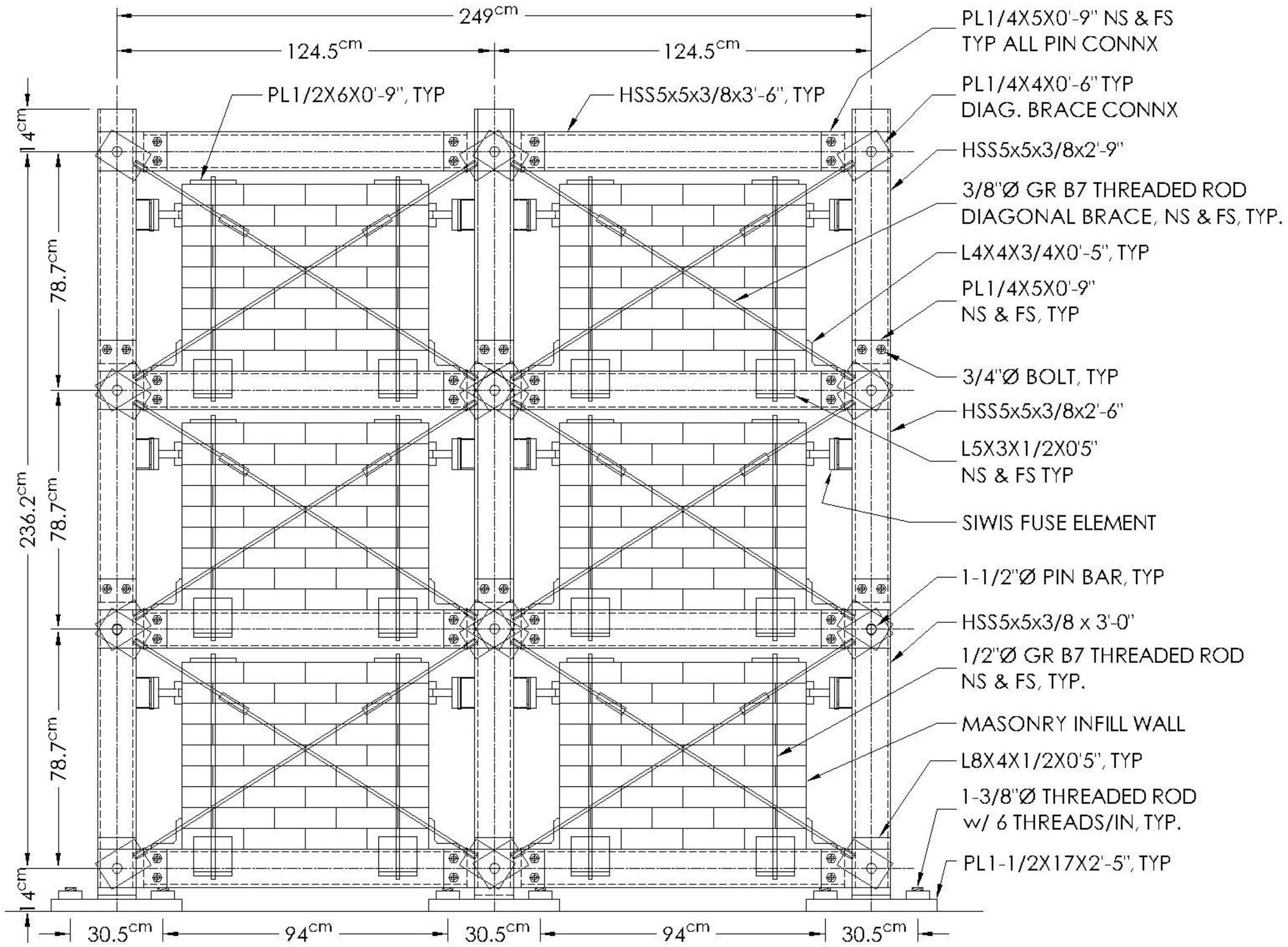
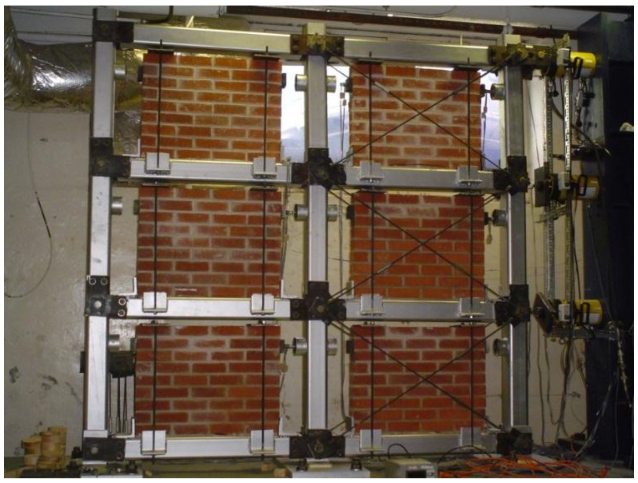
Both series of tests were performed on the 1/4 scale, two-bay, three-story steel test frame shown in
Figure 1 and
Figure 2, respectively. The test frame shown in
Figure 1 consists of HSS 127 mm × 127 mm × 9.5 mm (5 × 5 × 3/8 in.) hollow structural steel members pin connected using 38.1 mm diameter steel bars to allow for adequate floor movements during racking and to enable the study of the system in a braced (stiff) and partially braced (flexible) configuration. The masonry infill wall specimens were supported by the bottom beam of each bay of the test frame with a 152.5 mm gap between the sides of the walls and the HSS columns, and a gap of between 38.1 mm and 60.3 mm between the top of the walls and the upper beam. Steel angles were welded to the top of the support beams on either side of the infill panels to prevent the base of the walls from sliding in the in-plane direction. Out-of-plane movement at the bottom of the infill panels was prevented by steel angles welded to the sides of the HSS beams. In order to prevent overturning of the infill panels, steel plates were secured to the top of the walls using 12.7 mm diameter threaded rods bolted to the outstanding legs of these angles.
Figure 1.
1/4 scale, two-bay, three-story steel test frame.
Figure 1.
1/4 scale, two-bay, three-story steel test frame.
Figure 2.
Concrete test platform and steel reaction frame.
Figure 2.
Concrete test platform and steel reaction frame.
In-plane, lateral stability of the test frame was provided by diagonal steel bracing rods. In the fully braced configuration, a total of four diagonal braces were used in each bay, with two bracing rods on each side of the infill panels. For the half-brace configuration, bracing rods were used in only one bay of each story. The diagonal bracing system was designed so that in the fully braced configuration, the pin-jointed steel frame had the same in-plane stiffness as an equivalent steel frame with moment resisting connections. Each diagonal brace member consisted of two 9.5 mm diameter, Grade B7, threaded rods with opposite hand threads joined together using a special coupling nut with right-hand threads in one side and left-hand threads in the other. The bracing rods were attached to the test frame using steel connection plates that fit over the 38.1 mm diameter steel pin bars. The rods were attached to the connection plates using welded coupling nuts.
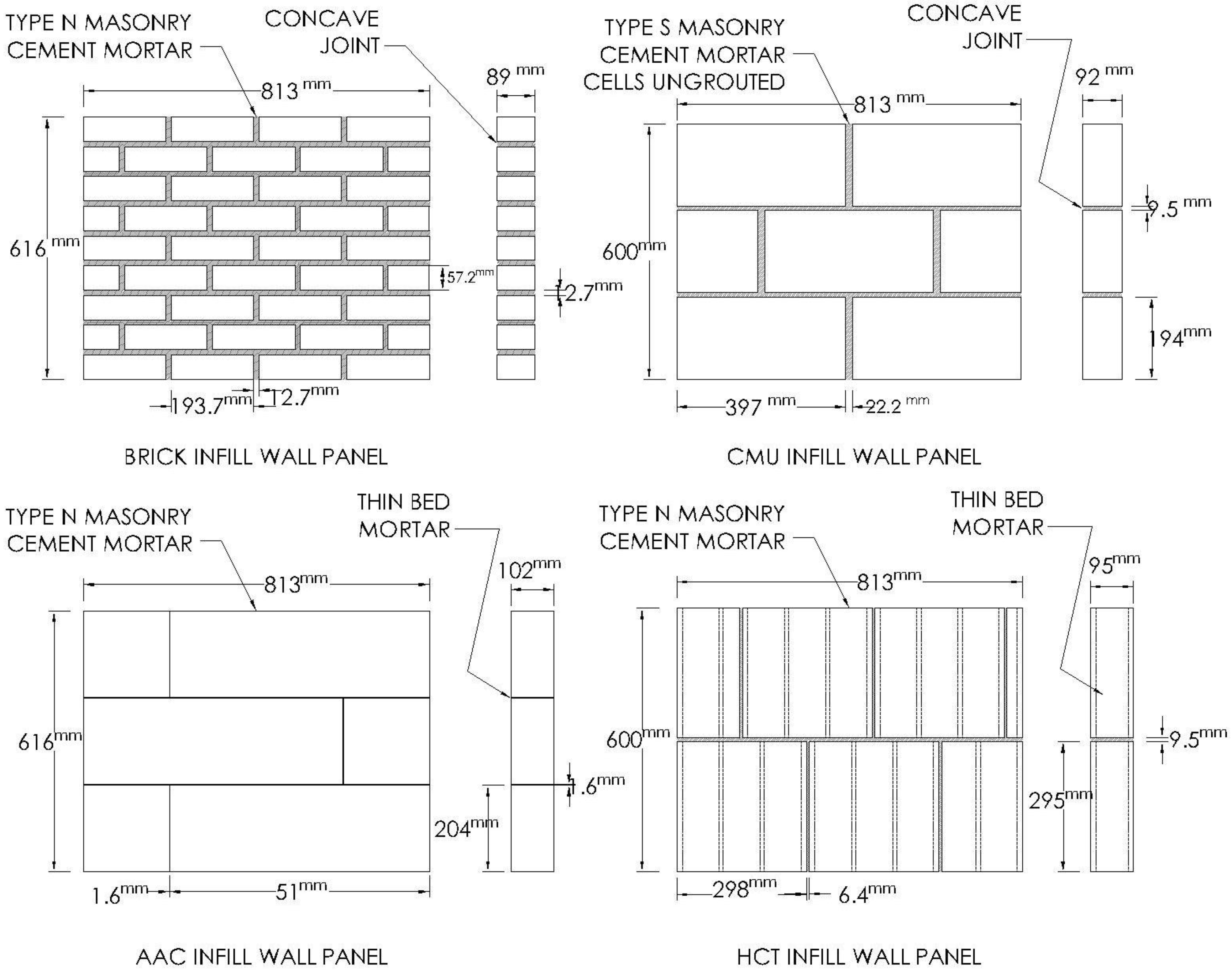
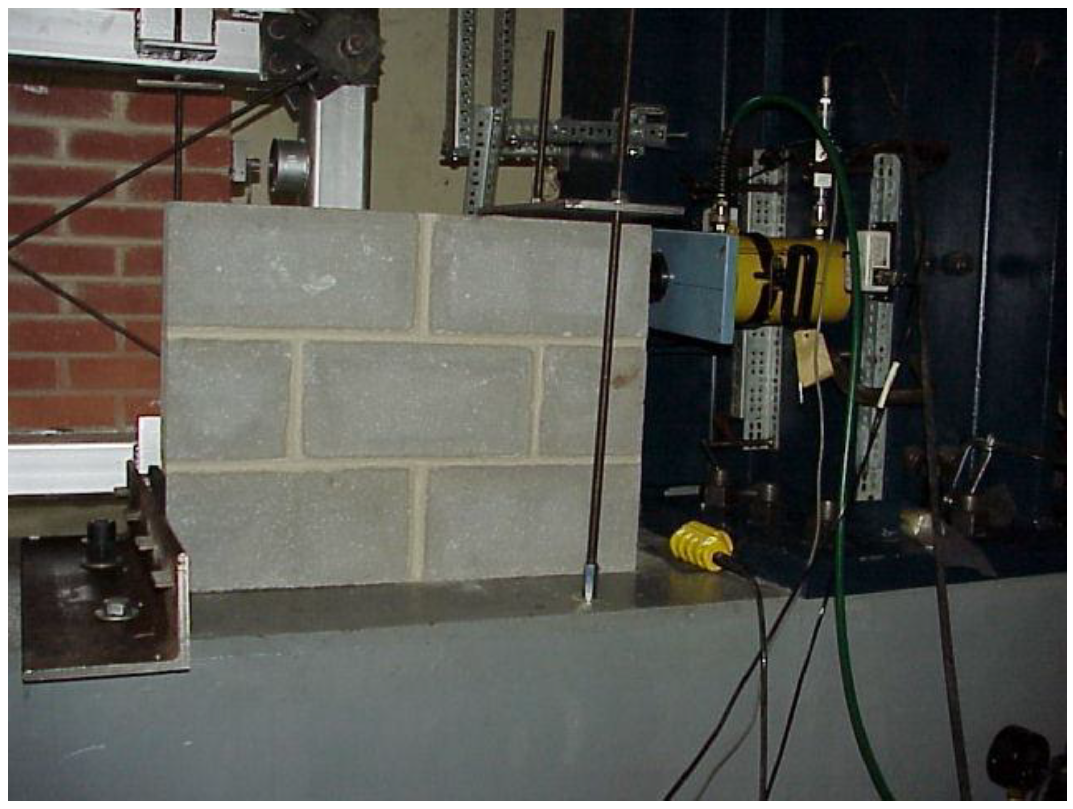
The masonry infill walls used in the cyclic and parametric tests were constructed in the BCERL test facility by professional masons. Destructive shear tests were performed to determine the in-plane shear strength of each type of masonry wall panel. The brick, CMU, AAC, and hollow clay tile (HCT) infill wall specimens used for this testing program are shown in
Figure 3. The brick wall panels were used for the cyclic tests, while the CMU and AAC specimens were used for the parametric study. The HCT infill wall specimens were included in the destructive shear tests, but not used in the structural fuse system tests due to their low in-plane shear capacity. The set-up for the destructive shear tests is shown in
Figure 4. The results of these tests are given in
Table 1.
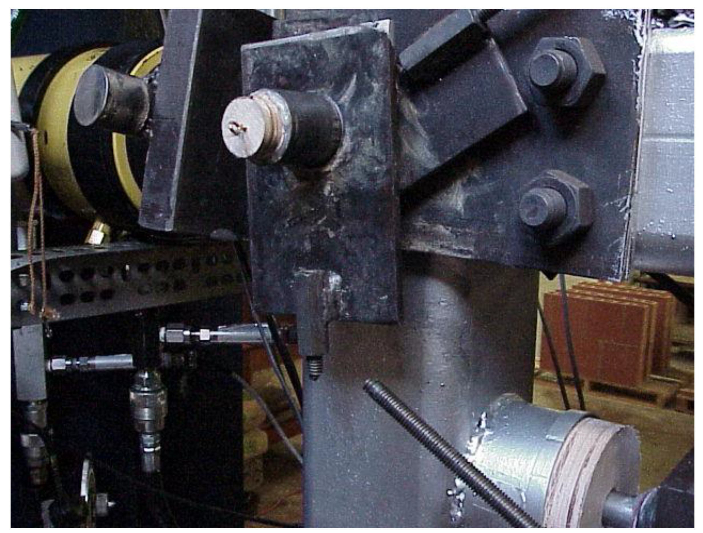
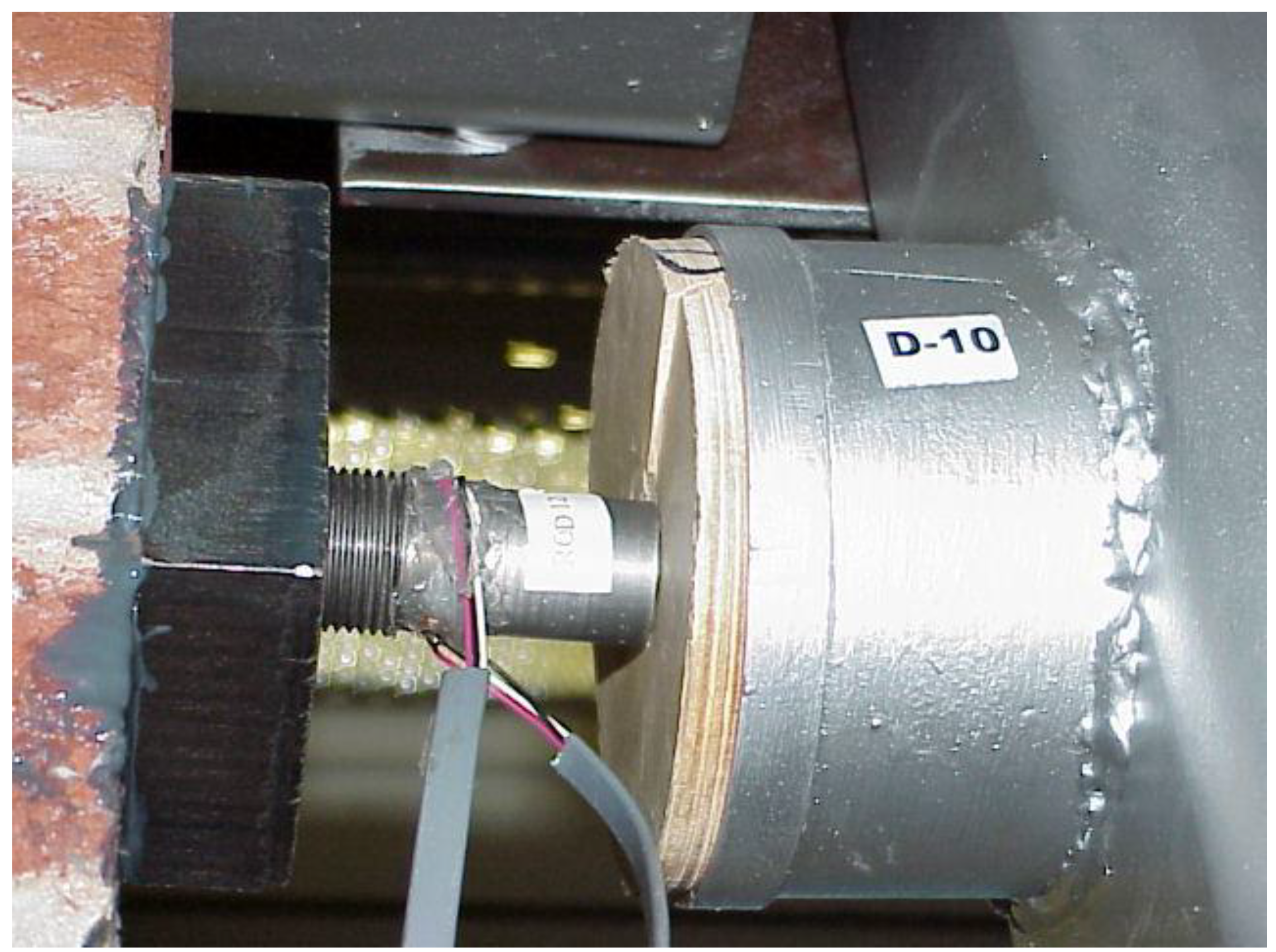
During the structural fuse system tests, lateral loads were applied to the test frame at each story level using hydraulic cylinders attached to the steel reaction frame shown in
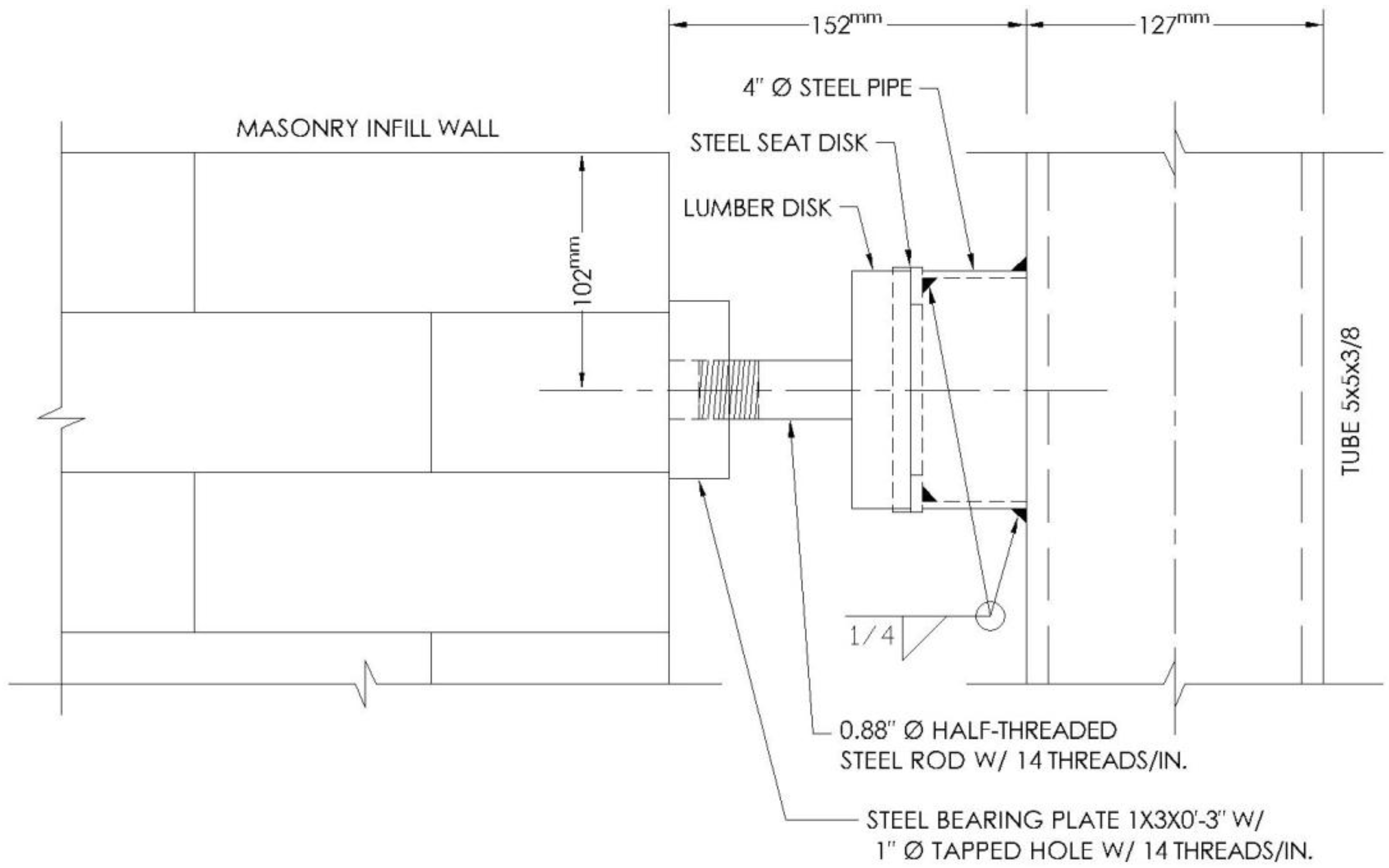
Figure 2. The in-plane lateral loads were transferred from the steel test frame to the masonry infill walls through the fuse mechanism shown in
Figure 5. As shown in this figure, the 100 mm diameter, lumber disk fuse elements were held in place by a steel seat disk and pipe assembly welded to the HSS columns near the top of the infill panels. The fuse punching mechanism consisted of a 22.4 mm diameter, half-threaded steel rod attached to a steel bearing plate which was epoxied to the infill panels. The lumber disk fuse elements used in the cyclic and parametric testing programs were cut from hard maple boards. Lumber disk puncture tests were performed to evaluate the strength of the fuse elements and determine the appropriate disk thickness to use with each type of masonry infill material [
29]. The results of the initial series of lumber disk puncture tests performed as part of this testing program are provided in
Table 2. The structural fuse test presented here builds on the results obtained from tests presented in an earlier study [
28] where different materials including concrete and wood disks were tested. The study also provided load-displacement diagrams for typical fuse elements and indicated that wood disks have better deformation capacity and provide desirable ductility for the infill wall system with fuse elements. Calibration issues related to the fuse elements as needed for the test programs may be found in the documents developed by Aliaari [
19] and Kauffman [
29].
Figure 3.
Masonry infill wall specimens.
Figure 3.
Masonry infill wall specimens.
Figure 4.
In-plane, destructive shear test set-up.
Figure 4.
In-plane, destructive shear test set-up.
Table 1.
Masonry wall panel shear tests results.
Table 1.
Masonry wall panel shear tests results.
| Wall Specimen | Masonry Material | Peak Capacity | Average | Standard Deviation | Coefficient of Variation | Stiffness | Average | Standard Deviation | Coefficient of Variation |
|---|
| kN | kN | kN | CV% | kN/mm | kN/mm | kN/mm | CV% |
|---|
| W1 | AAC | 61.47 | 56.8 | 6.2 | 11.3 | 5.62 | 7.0 | 1.5 | 21.3 |
| W2 | AAC | 52.09 | 6.37 |
| W3 | AAC | 61.16 | 8.27 |
| W4 | AAC | 52.44 | 7.76 |
| W5 | CMU | 114.50 | 97.7 | 20.0 | 20.5 | 13.38 | 15.5 | 2.3 | 14.7 |
| W6 | CMU | 108.49 | 16.41 |
| W7 | CMU | 87.36 | 17.64 |
| W8 | CMU | 80.51 | 14.73 |
| W9 | HCT | 9.70 | 18.6 | 6.2 | 78.4 | 1.66 | 3.7 | 1.5 | 80.5 |
| W10 | HCT | 27.49 | 5.66 |
Figure 5.
Fuse mechanism detail.
Figure 5.
Fuse mechanism detail.
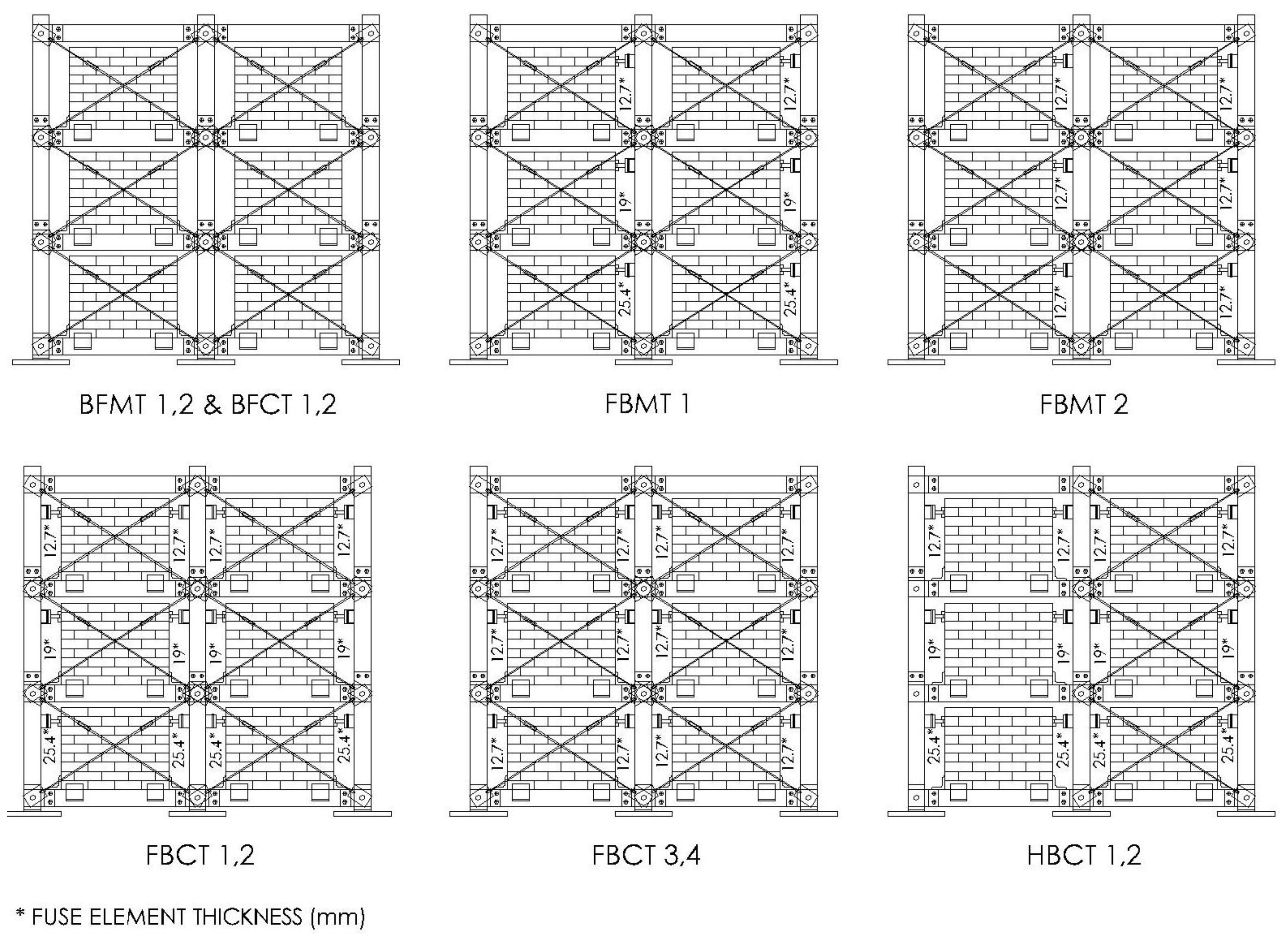
For the cyclic testing program, quasi-static, displacement-controlled loads were applied simultaneously at the first, second and third story levels using three hydraulic jacks. Two different bracing configurations were tested, including full-brace and half-brace, in order to observe the performance of the structural fuse system for frames with different in-plane stiffness properties. The fuse element thicknesses were also varied. For some of the tests, the same fuse element thickness was used at each story level. For other tests, a different fuse element thickness was used at each story level. A test matrix of the cyclic testing program is given in
Table 3. As the table indicates, the test specimen included bare frame, full brace, and half brace configurations. Diagrams of each test configuration are shown in
Figure 6.
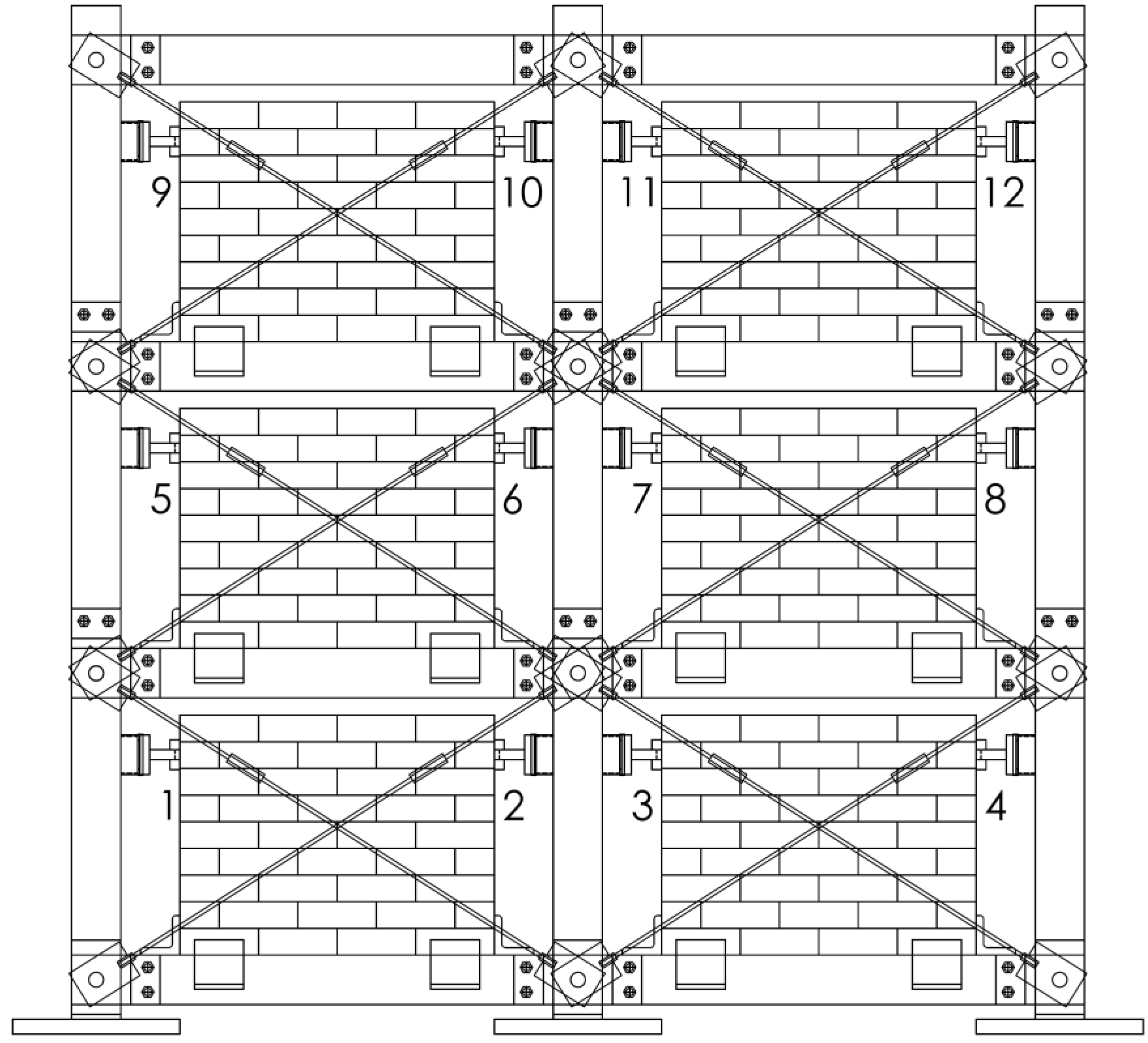
Figure 7 shows the location of the fuse elements on the steel test frame during the cyclic tests. The data collected during the cyclic tests included the load applied to the test frame by the hydraulic cylinders, the in-plane deflection of the test frame at each story level, and the shear forces transferred from the test frame to the brick infill walls through the structural fuse elements.
Table 2.
Lumber disk puncture test results.
Table 2.
Lumber disk puncture test results.
| Disk Specification | Thickness | Weight | Volume | Density | Average | Standard Deviation | Coefficient of Variation | Capacity | Average | Standard Deviation | Coefficient of Variation |
|---|
| mm | gr | cm3 | gr/cm3 | gr/cm3 | gr/cm3 | CV% | kN | kN | kN | CV% |
|---|
| D1 | 12.9 | 74.9 | 100.9 | 0.74 | 0.72 | 0.0249 | 3.3 | 8.47 | 10.66 | 1.97 | 18.5 |
| D2 | 12.9 | 74.0 | 100.9 | 0.73 | 11.21 |
| D3 | 12.9 | 70.4 | 100.9 | 0.70 | 12.29 |
| D4 | 19.1 | 106.7 | 149.1 | 0.72 | 0.71 | 0.0111 | 1.7 | 18.72 | 19.11 | 0.37 | 1.9 |
| D5 | 19.3 | 108.5 | 151.1 | 0.72 | 19.16 |
| D6 | 19.3 | 105.1 | 151.1 | 0.70 | 19.46 |
| D7 | 25.4 | 139.4 | 197.9 | 0.70 | 0.70 | 0.00830 | 1.2 | 22.46 | 21.99 | 1.87 | 8.5 |
| D8 | 25.6 | 142.3 | 199.8 | 0.71 | 19.94 |
| D9 | 25.4 | 137.6 | 197.8 | 0.70 | 23.59 |
| D10 | 38.3 | 243.1 | 301.7 | 0.81 | 0.77 | 0.0498 | 6.4 | 38.31 | 37.05 | 1.41 | 3.8 |
| D11 | 38.1 | 236.1 | 298.2 | 0.79 | 35.53 |
| D12 | 38.1 | 215.2 | 301.2 | 0.71 | 37.32 |
Table 3.
Cyclic testing program test matrix.
Table 3.
Cyclic testing program test matrix.
| Test | Type | Description | Fuse Element Thickness (mm) |
|---|
| 1st Story | 2nd Story | 3rd Story |
|---|
| BFMT1 | Bare Frame Monotonic Test | Fully braced, no fuse elements | NA | NA | NA |
| BFMT2 | Bare Frame Monotonic Test | Fully braced, no fuse elements | NA | NA | NA |
| FBMT1 | Full Brace Monotonic Test | Fully braced, with fuse elements | 25.4 | 19.1 | 12.7 |
| FBMT2 | Full Brace Monotonic Test | Fully braced, with fuse elements | 0.5 | 12.7 | 12.7 |
| BFCT1 | Bare Frame Cyclic Test | Fully braced, no fuse elements | NA | NA | NA |
| BFCT2 | Bare Frame Cyclic Test | Fully braced, no fuse elements | NA | NA | NA |
| FBCT1 | Full Brace Cyclic Test | Fully braced, with fuse elements | 25.4 | 19.1 | 12.7 |
| FBCT2 | Full Brace Cyclic Test | Fully braced, with fuse elements | 25.4 | 19.0 | 12.7 |
| FBCT3 | Full Brace Cyclic Test | Fully braced, with fuse elements | 12.7 | 12.7 | 12.7 |
| FBCT4 | Full Brace Cyclic Test | Fully braced, with fuse elements | 12.7 | 12.7 | 12.7 |
| HBCT1 | Half Brace Cyclic Test | Half braced, with fuse elements | 25.4 | 19.1 | 12.7 |
| HBCT2 | Half Brace Cyclic Test | Half braced, with fuse elements | 25.4 | 19.1 | 12.7 |
Figure 6.
Test frame configurations for cyclic test program.
Figure 6.
Test frame configurations for cyclic test program.
Figure 7.
Fuse element locations on test frame.
Figure 7.
Fuse element locations on test frame.
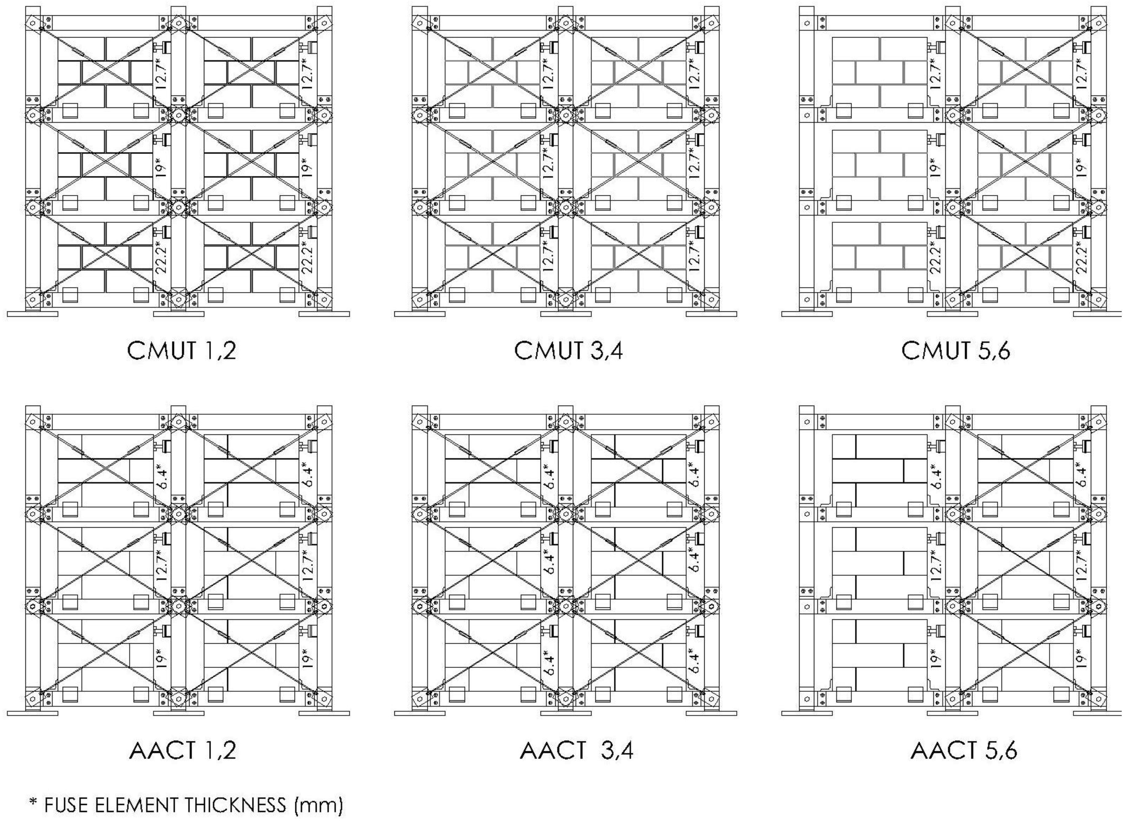
For the parametric tests, monotonic loads were applied at the third story of the test frame using one hydraulic cylinder. As with the cyclic tests, varying fuse element thicknesses and bracing configurations were tested. A test matrix for the parametric test series is given in
Table 4.
Figure 8 shows typical elevations of the fully braced and half braced specimens. The data collected during these tests included the load applied at the third story level of the test frame by the hydraulic cylinder, and the in-plane deflection of the test frame at each story level.
Table 4.
Parametric testing program test matrix.
Table 4.
Parametric testing program test matrix.
| Test | Masonry Material | Description | Fuse Element Thickness (mm) |
|---|
| First Story | Second Story | Third Story |
|---|
| CMUT1 | CMU | Fully braced, with fuse elements | 22.2 | 19.1 | 12.7 |
| CMUT2 | CMU | Fully braced, with fuse elements | 22.2 | 19.1 | 12.7 |
| CMUT3 | CMU | Fully braced, with fuse elements | 12.7 | 12.7 | 12.7 |
| CMUT4 | CMU | Fully braced, with fuse elements | 12.7 | 12.7 | 12.7 |
| CMUT5 | CMU | Half braced, with fuse elements | 22.2 | 19.1 | 12.7 |
| CMUT6 | CMU | Half braced, with fuse elements | 22.2 | 19.1 | 12.7 |
| AACT1 | AAC | Fully braced, with fuse elements | 19.1 | 12.7 | 6.4 |
| AACT2 | AAC | Fully braced, with fuse elements | 19.1 | 12.7 | 6.4 |
| AACT3 | AAC | Fully braced, with fuse elements | 6.4 | 6.4 | 6.4 |
| AACT4 | AAC | Fully braced, with fuse elements | 6.4 | 6.4 | 6.4 |
| AACT5 | AAC | Half braced, with fuse elements | 19.1 | 12.7 | 6.4 |
| AACT6 | AAC | Half braced, with fuse elements | 19.1 | 12.7 | 6.4 |
Figure 8.
Test frame configurations for parametric testing program.
Figure 8.
Test frame configurations for parametric testing program.
3. Monotonic and Cyclic Tests with Brick Infill Panels
3.1. Bare Frame Monotonic Tests
At the beginning of the cyclic testing program, bare frame monotonic tests were performed without fuse elements, so that the test frame could act independently from the infill walls. The full bracing configuration was used with all the diagonal bracing rods in place. The goal of these tests was to simulate a first mode, inverted triangle test frame displacement shape by applying simultaneous, displacement controlled loads at each story level using three hydraulic cylinders. According to Tomazevic and Klemenc [
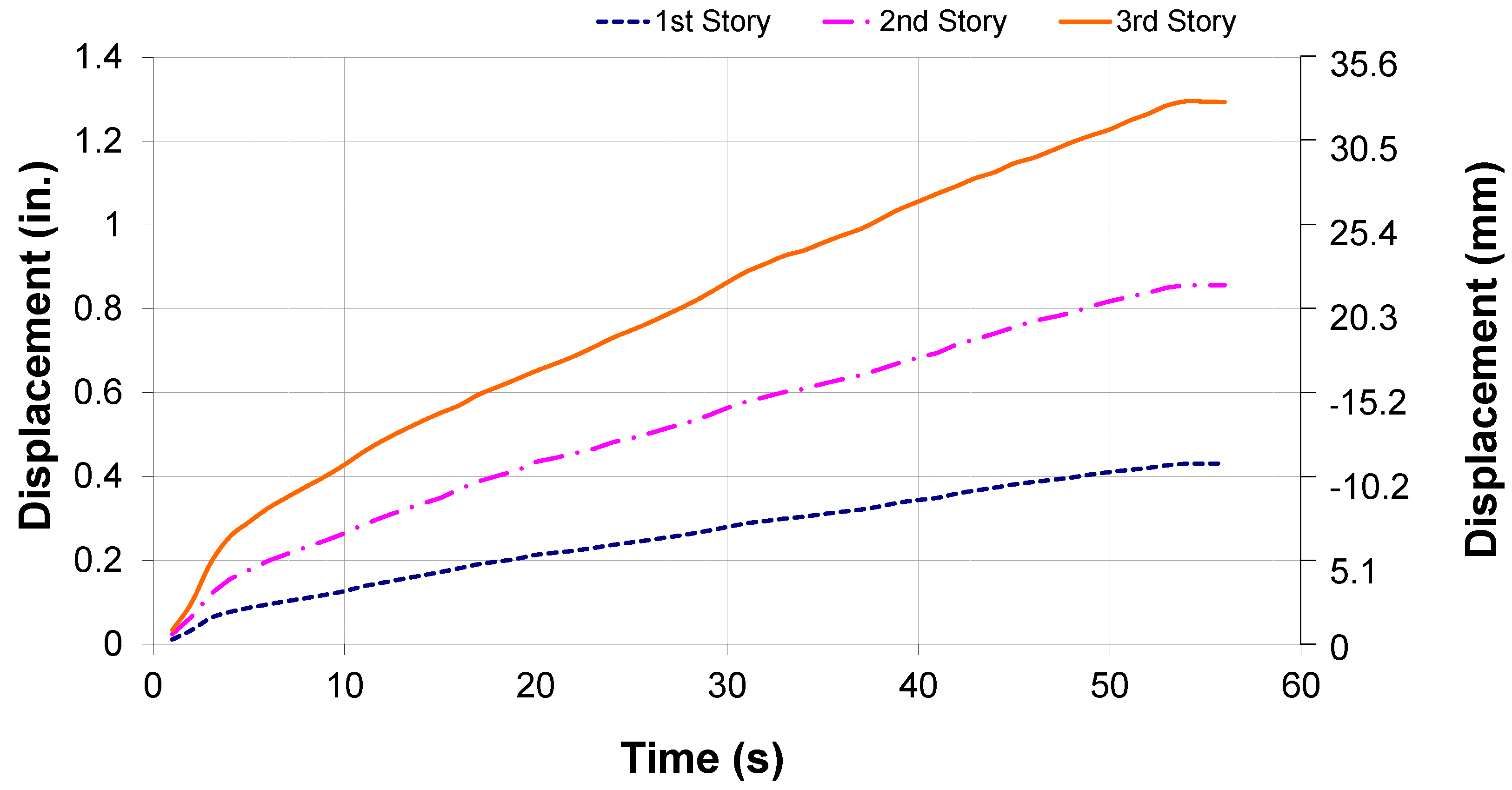
30], the dominant mode shape for masonry structures is typically the first mode response, which is characterized by an inverted triangle shape. The story displacement histories from BFMT2 (bare frame monotonic test 2), given in
Figure 9, show that the displacements applied at each story level during this test resulted in an inverted triangle displacement shape of the test frame. During both bare frame monotonic tests, the force applied by the cylinder at the third story of the test frame was much greater than the load applied at the first and second story levels. For both of these tests, the maximum force applied at the third story level was between 10,680 N and 11,120 N, while the max force applied at the second and first story levels was less than 890 N. Since the geometry and stiffness of the bracing members was the same at each story level, the frame naturally assumed an inverted triangle deflection shape, and very little load needed to be applied at the first and second story levels to maintain this mode shape.
Figure 9.
Bare frame cyclic test 2 (BFMT2) displacement history.
Figure 9.
Bare frame cyclic test 2 (BFMT2) displacement history.
3.2. Full Brace Monotonic Tests
After an appropriate loading procedure was determined for producing a first mode response in the test frame, full brace monotonic tests were performed with fuse elements in place acting on the brick infill panels. For these tests, structural fuse elements were installed on the compression side of each brick infill panel. For FBMT1 (full brace monotonic test 1), the thickness of the fuse elements at the first, second, and third stories were 25.4 mm, 19.1 mm, and 12.7 mm, respectively. For test FBMT2, 12.7 mm thick disks were used at every story level. For both of these tests the full brace configuration was used with all the diagonal bracing rods in place on the test frame.
The purpose of these tests was to define the parameters for the quasi-static load history [
31]. These parameters include the deformation level at which the test specimens begin to behave inelastically, the increment in peak deformation between subsequent load steps, and the number of individual cycles performed at each load step. According to the loading protocol [
31], after reaching the yield value of the deformation control parameter, δ
y, the increment in peak deformation, Δ, should be constant for subsequent load steps. For the structural fuse system tests, inelastic behavior occurs at the onset of cracking in the lumber disk fuse elements.
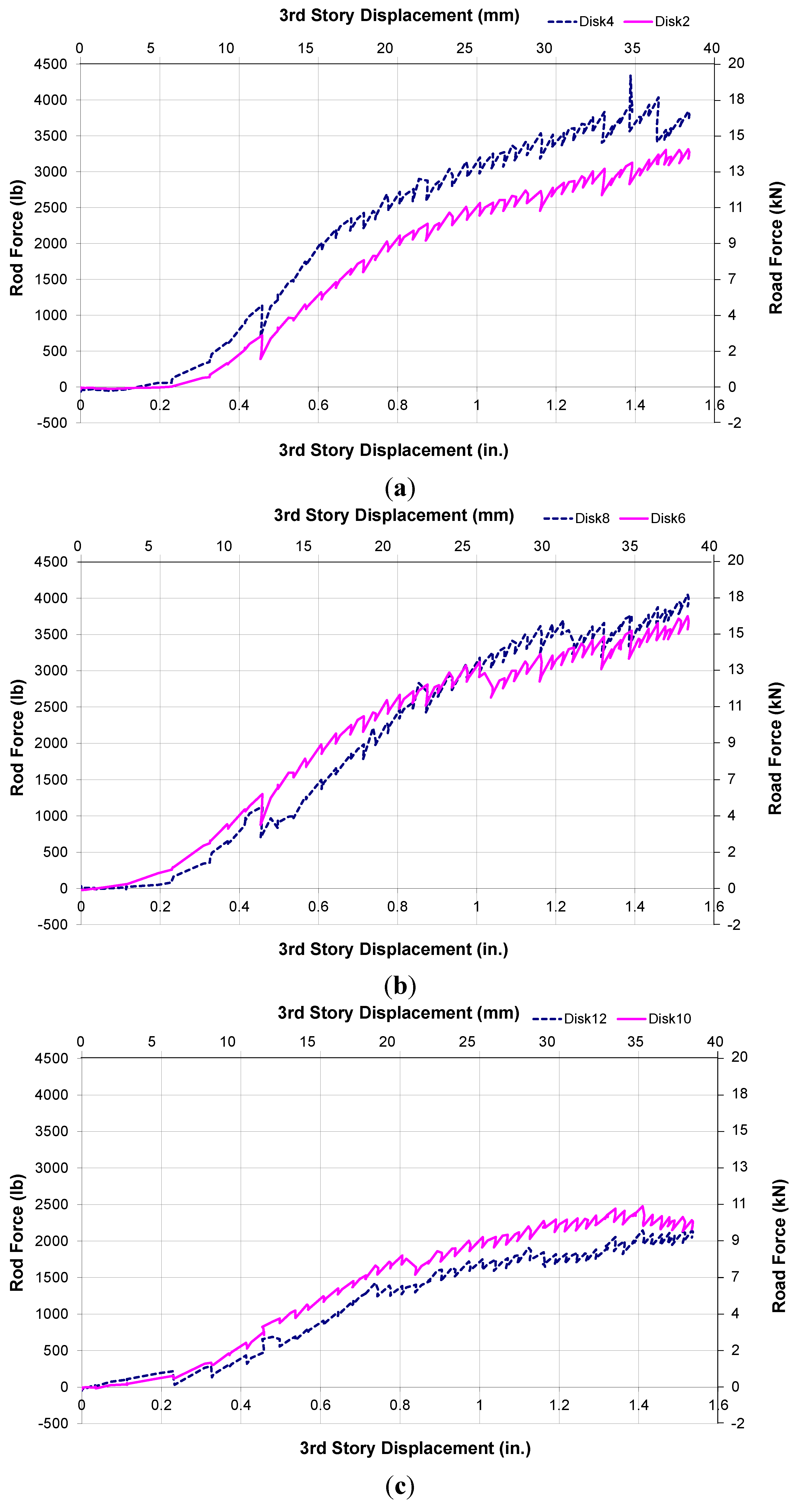
During both of the full brace monotonic tests, the desired story level displacement ratios were maintained resulting in an inverted triangle displacement shape of the test frame. As with the bare frame monotonic tests, the force applied by the hydraulic cylinder at the third story level was greater than the force applied by the cylinders at the first and second levels. The maximum punching rod forces measured at each disk location during both tests are given in
Table 5. Plots of the force in the steel rod at each fuse element location
vs. the third story frame deflection for test FBMT1 are given in
Figure 10.
Table 5.
Full brace monotonic test (FBMT) fuse forces.
Table 5.
Full brace monotonic test (FBMT) fuse forces.
| Story Level | Test Label | Fuse Thickness (mm) | Fuse Location | Maximum Fuse Force (kN) | Average Fuse Force (kN) |
|---|
| First Story | FBMT1 | 25.4 | Fuse 2 | 14.55 | 16.92 |
| Fuse 4 | 19.30 |
| FBMT2 | 12.7 | Fuse 2 | 11.30 | 11.21 |
| Fuse 4 | 11.11 |
| Second Story | FBMT1 | 19.1 | Fuse 6 | 16.69 | 17.35 |
| Fuse 8 | 18.02 |
| FBMT2 | 12.7 | Fuse 6 | 9.96 | 10.86 |
| Fuse 8 | 11.77 |
| Thirde Story | FBMT1 | 12.7 | Fuse 10 | 11.01 | 10.28 |
| Fuse 12 | 9.54 |
| FBMT2 | 12.7 | Fuse 10 | 11.11 | 10.78 |
| Fuse12 | 10.46 |
During the full brace monotonic tests, the brick infill panels contributed a significant amount of strength to the overall in-plane load resistance of the test frame.
Table 6 summarizes the total in-plane load transferred to the infill panels through the fuse elements at each story level during tests FBMT1 and FBMT2 at the third story displacement intervals of 10.2 mm, 20.3 mm, and 30.5 mm. The greatest percentage of the total in-plane load was transferred through the fuse elements at a third story displacement of 25.4 mm. When the third story displacement reached 30.5 mm, a smaller percentage of the in-plane load was transferred to the infill walls since the fuse elements had experienced more damage by this point in the test. Even after the fuse elements experienced significant damage, some of the in-plane load was still transferred through the fuse elements to the infill walls.
Figure 10.
Test FBMT1 punching rod force histories. (a) FBMT1 1st story rod histories; (b) FBMT1 2nd story rod histories; (c) FBMT1 3rd story rod histories.
Figure 10.
Test FBMT1 punching rod force histories. (a) FBMT1 1st story rod histories; (b) FBMT1 2nd story rod histories; (c) FBMT1 3rd story rod histories.
Table 6.
Fuse forces transferred to infill panels during full brace monotonic tests.
Table 6.
Fuse forces transferred to infill panels during full brace monotonic tests.
| Test Identification | 3rd Story Displacement (mm) | Combined Fuse Force (kN) | Total Fuse Force * (kN) | Total Applied Load (kN) | % Total Load in Fuses (kN) |
|---|
| 1st Story | 2nd Story | 3rd Story |
|---|
| FBMT1 | 10.2 | 6.24 | 8.69 | 4.62 | 19.55 | 33.66 | 58.1 |
| 20.3 | 20.73 | 21.87 | 14.17 | 56.77 | 87.91 | 64.6 |
| 30.5 | 30.28 | 29.82 | 17.71 | 77.81 | 144.05 | 54.0 |
| FBMT2 | 10.2 | 5.28 | 5.16 | 7.39 | 17.84 | 30.99 | 57.6 |
| 20.3 | 17.32 | 17.25 | 14.42 | 48.98 | 79.52 | 61.6 |
| 30.5 | 21.33 | 19.31 | 20.24 | 60.88 | 142.69 | 42.7 |
During tests FBMT1 and FBMT2, the first fuse element cracking occurred at a third story displacement of between 7.6 mm and 12.7 mm. Based on these results, the value δ
y for the quasi-static loading protocol was set equal to a third story test frame displacement level of 12.7 mm. The upper bound of the third story displacement corresponding to fuse element crack initiation was chosen based on the loading protocol guidelines [
32] that at least two load steps be performed before the deformation applied to the test specimen reaches δ
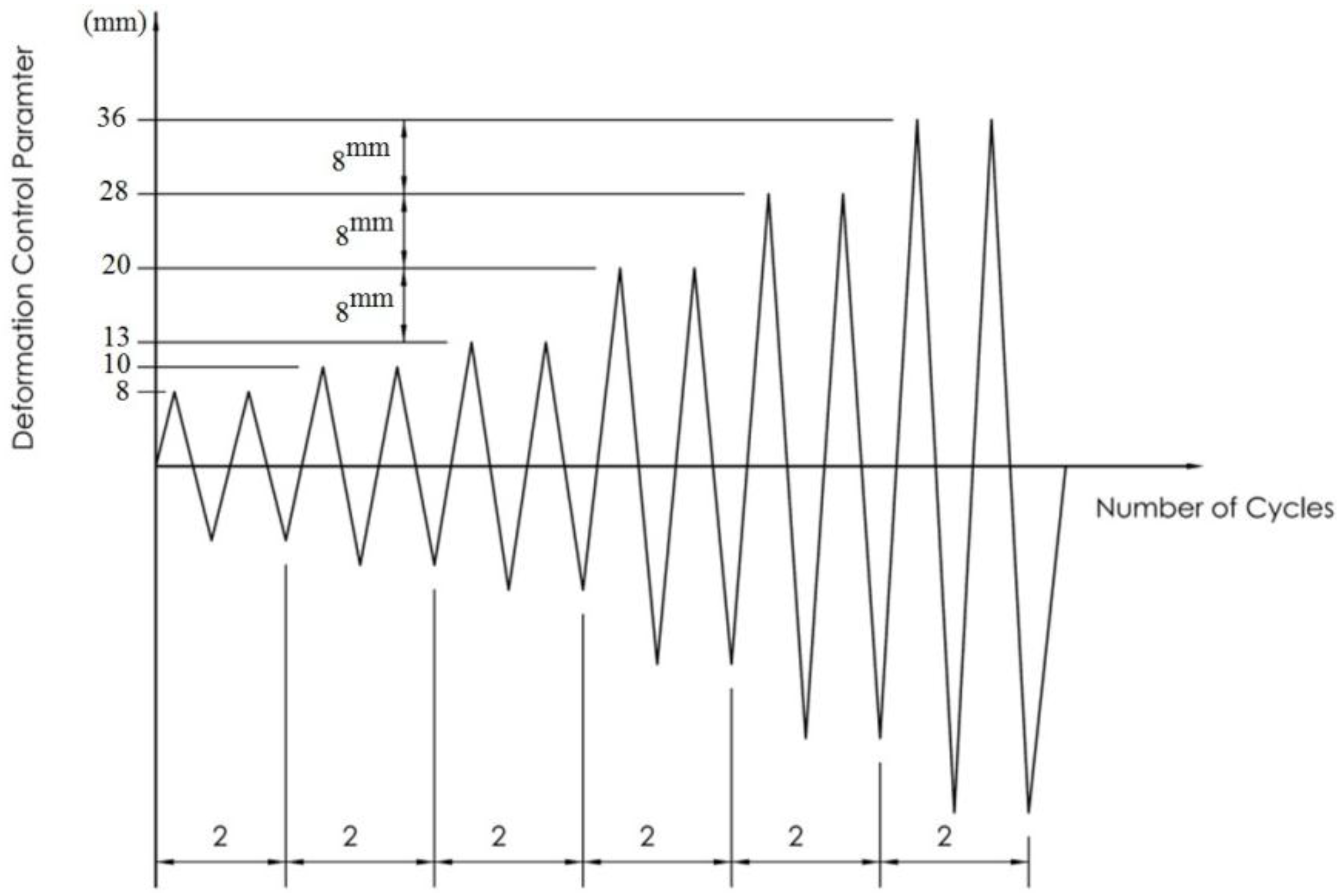
y. In order to prevent damage to the steel bracing rods, the maximum third story displacement level applied to the test frame during the cyclic tests was 35.6 mm. To allow for the maximum number of steps in the cyclic loading history, a third story displacement increment of 7.6 mm was chosen for the increment in peak deformation between load steps. A total of two load cycles were performed during each load step. The quasi-static loading protocol used for the cyclic tests is shown in
Figure 11.
Figure 11.
Quasi-static cyclic loading history.
Figure 11.
Quasi-static cyclic loading history.
3.3. Bare Frame Cyclic Tests
The bare frame cyclic tests were performed with all of the bracing rods in place on the test frame and no fuse elements. During these tests, displacement controlled loads were applied in both in-plane directions (advance and retract) based on the quasi-static loading protocol shown in
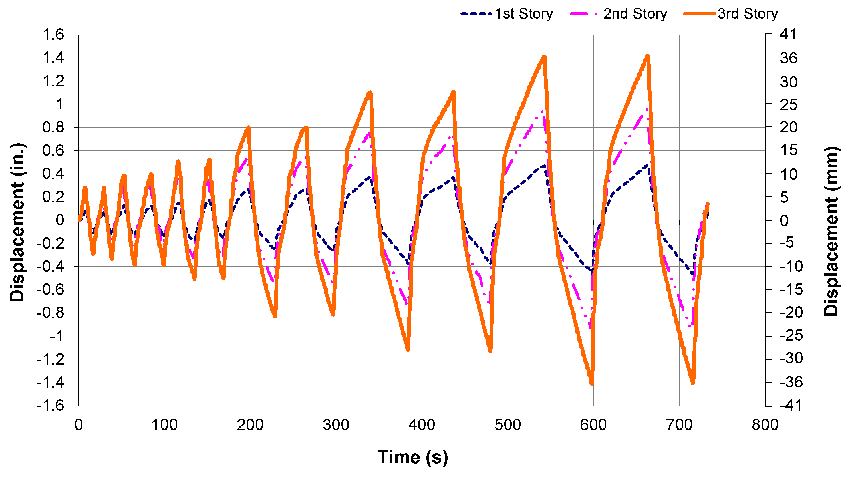
Figure 11. The load applied at each story was controlled manually using a separate hydraulic pump attached to each of the load cylinders. The story level displacement histories for test BFCT1 (bare frame cyclic test 1) are shown in
Figure 12. The story level load histories for test BFCT1 are shown in
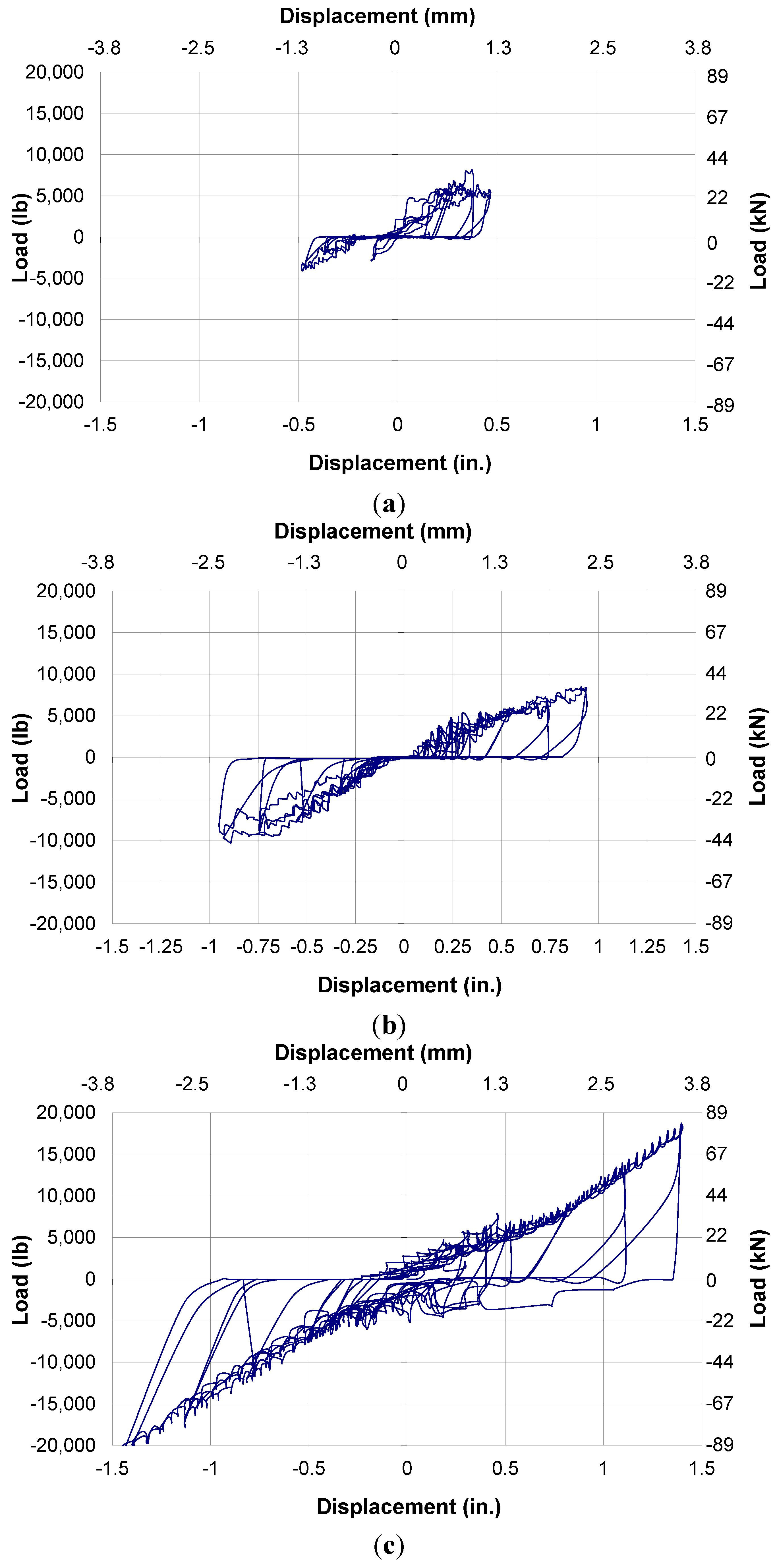
Figure 13. The load-displacement, hysteretic behavior at the first, second, and third story levels of the test frame during test BFCT1 is shown in
Figure 14. In these figures the load applied at each story of the test frame is plotted
vs. the displacement measured at that story. The hysteretic plots are fairly symmetrical at story levels two and three for both of the bare frame cyclic tests. This indicates that the work done by the hydraulic cylinders on the test frame at these story levels was similar in both in-plane directions of the load cycle. At the first story level, however, the work done by the cylinders on the test frame was not symmetrical with respect to the direction of the applied load.
Figure 12.
Bare frame cyclic test BFCT1 displacement history.
Figure 12.
Bare frame cyclic test BFCT1 displacement history.
Figure 13.
Bare frame cyclic test BFCT1 load history.
Figure 13.
Bare frame cyclic test BFCT1 load history.
Figure 14.
Test BFCT1 load-deflection hysteretic behavior. (a) BFCT1 1st story hysteretic behavior; (b) BFCT1 2nd story hysteretic behavior; (c) BFCT1 3rd story hysteretic behavior.
Figure 14.
Test BFCT1 load-deflection hysteretic behavior. (a) BFCT1 1st story hysteretic behavior; (b) BFCT1 2nd story hysteretic behavior; (c) BFCT1 3rd story hysteretic behavior.
During both bare frame cyclic tests, the load applied to the test frame by the hydraulic cylinders at the third story level was greater than the load applied at the first and second story levels in the advance and retract directions. This behavior was also observed during the bare frame monotonic tests. For the bare frame cyclic tests, however, a greater percentage of the total in-plane load was applied at the first and second story levels than during the monotonic bare frame tests. Although the displacement controlled loads were applied in the same manner during these tests, the quasi-static loading protocol used for the cyclic tests resulted in more load at the first and second stories. These results show that the quasi-static loading history produces a more realistic seismic loading simulation than the monotonic loading protocol.
3.4. Fill Brace Cyclic Tests
The full brace cyclic tests were performed with all diagonal bracing rods in place on the test frame. For these tests, lumber disk fuse elements were positioned on the test frame at the fuse mechanism locations on both sides of the brick infill walls. Tests FBCT1 (full brace cyclic test 1) and FBCT2 were performed with 25.4 mm lumber disk fuse elements at the first story, 19.1 mm fuse elements at the second story, and 12.7 mm fuse elements at the third story. For tests FBCT3 and FBCT4, 12.7 mm fuse elements were used at each story level. The same loading protocol and procedure used for the bare frame cyclic tests were used for the full brace cyclic tests. In-plane loads were applied to the test frame in the advance and retract directions at each story level. The displacement history at the third story level was applied according to the same quasi-static loading protocol used for the bare frame cyclic tests, while the displacements at the first and second stories were based as necessary to achieve an inverted triangle displacement shape.
The response of the test frame to the applied in-plane loads during the full brace cyclic tests was similar to the behavior observed for the full brace monotonic tests. At the start of each test, there was an initial tightening of the system as incrementally increasing displacements were applied to the test frame at each story level in the advance (forward) direction. During this period, the steel bracing rods that were in tension began to tighten, while the steel bracing rods in compression started to buckle. As additional load was applied to the test frame by the hydraulic cylinders, the 22.4 mm dia., half-threaded steel punching rods connecting the fuse elements to the steel test frame began to push on the lumber disk fuses as shear forces were transferred from the steel frame to the infill panels at the upper compression corner of the brick panels. At the same time, the lower compression corners of the infill panels were pressed against the 19.1 mm × 102 mm × 102 mm (3/4 × 4 × 4 in.) steel angles welded to the top of the HSS 127 mm × 127 mm × 9.5 mm (5 × 5 × 3/8 in.) beams.
When the displacement of the third story of the test frame reached the maximum deformation level for that load step, the direction of the load applied by the hydraulic cylinders at each story level was reversed. Load was then applied in the retract (reverse) direction and the test frame was returned to the initial condition of zero displacement at each story level. As additional load was applied in the retract direction, the bracing rods that had previously been in tension began to buckle in compression while the rods that had been in compression during the advance portion of the load cycle began to elongate in tension. The same fuse element behavior observed in the advance direction of the load cycle was also seen in the retract direction. As the displacements at each story level were increased in the retract direction, the fuse elements on the opposite side of the test frame began to transfer shear forces from the steel frame to the infill walls.
For these tests, the target maximum displacement at the third story of the test frame during the first two load steps was 7.6 mm and 10.2 mm, respectively. These values were chosen during the development of the quasi-static loading protocol so that two load steps could be performed before inelastic deformation occurred in the test specimens. During these tests, noticeable cracking did not occur in the lumber disk fuse elements until the displacement at the third story of the test frame reached or exceeded a value of 12.7 mm, during or after the third load step. These results confirmed that the target third story displacement values chosen for the first two load steps were appropriate.
Initial cracking of the lumber disk fuse elements typically occurred during the first cycle of the third load step. The target maximum third story displacement for the third load step was 12.7 mm. Additional cracking occurred in the fuse elements as the magnitude of the third story displacement was increased during subsequent load steps. Two load cycles were completed at each deformation level. After the second cycle, additional fuse cracking did not occur until the displacement of the test frame exceeded the peak third story displacement value of that load step during the next load cycle. This behavior confirmed that two cycles per load step were sufficient to capture the inelastic frame behavior at a given deformation level.
Diagonal bracing rod failures occurred during the final load step of tests FBCT1, FBCT2, and FBCT4. The failures occurred at the ends of the braces near the connection, as shown in
Figure 15. Based on the results of rod tension tests performed by Aliaari [
19], the bracing rods reach their yield point at a tensile load of around 31.6 kN and have an ultimate capacity of around 37.8 kN. The average total in-plane load applied to the test frame in either direction during both cycles of the final load step was around 141.9 kN. Depending on the proportion of the total in-plane load transferred to the infill walls by the fuse elements during this final load step, the force experienced by the bracing rods at the first story level of the test frame was between 31.1 kN and 35.6 kN. According to this data, the bracing rods were near or at their yield point during the final load step of the cyclic tests.
Figure 15.
Typical bracing rod failure.
Figure 15.
Typical bracing rod failure.
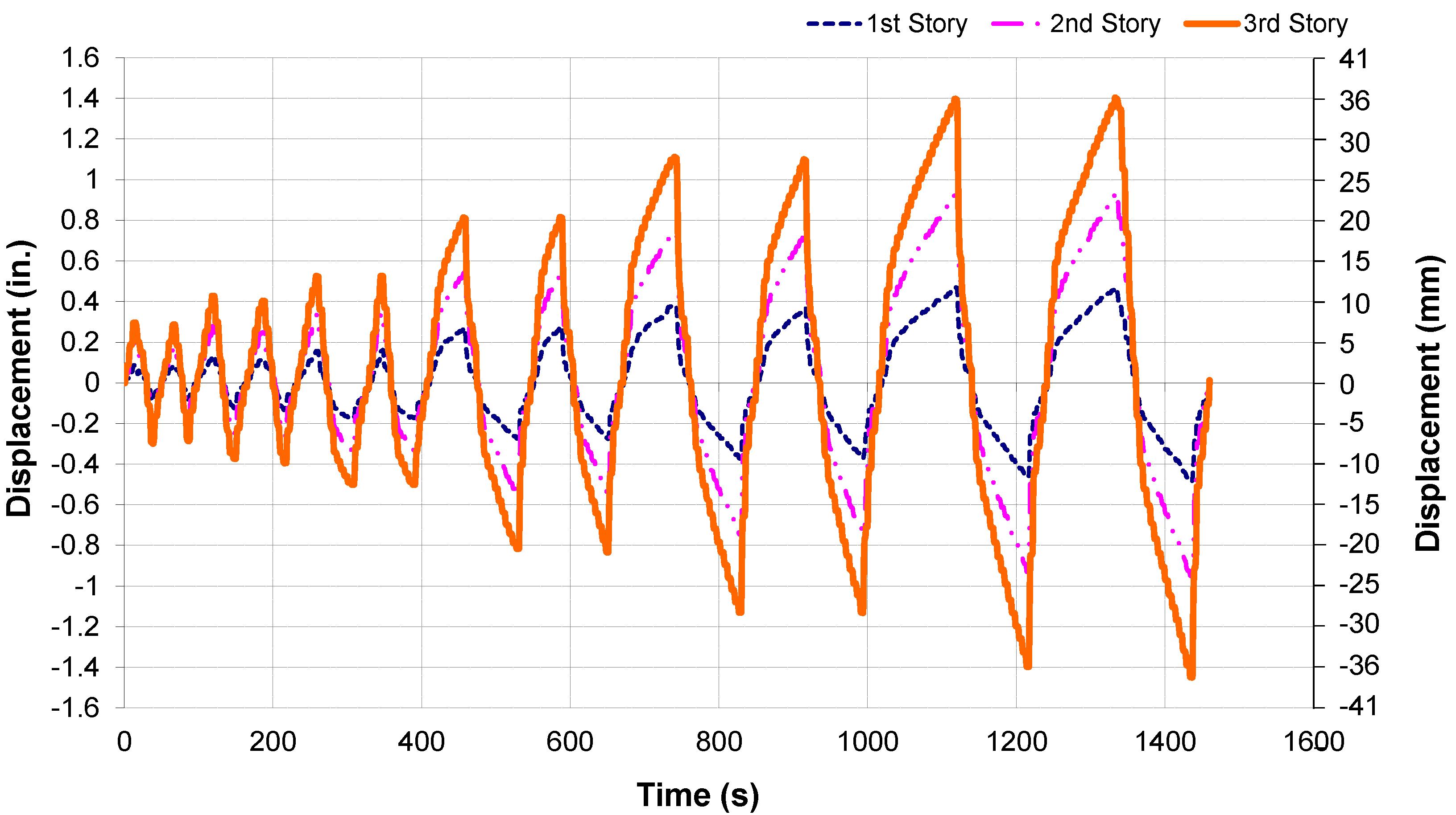
The displacement histories for full brace cyclic tests for tests FBCT2 and FBCT4 are shown in
Figure 16 and
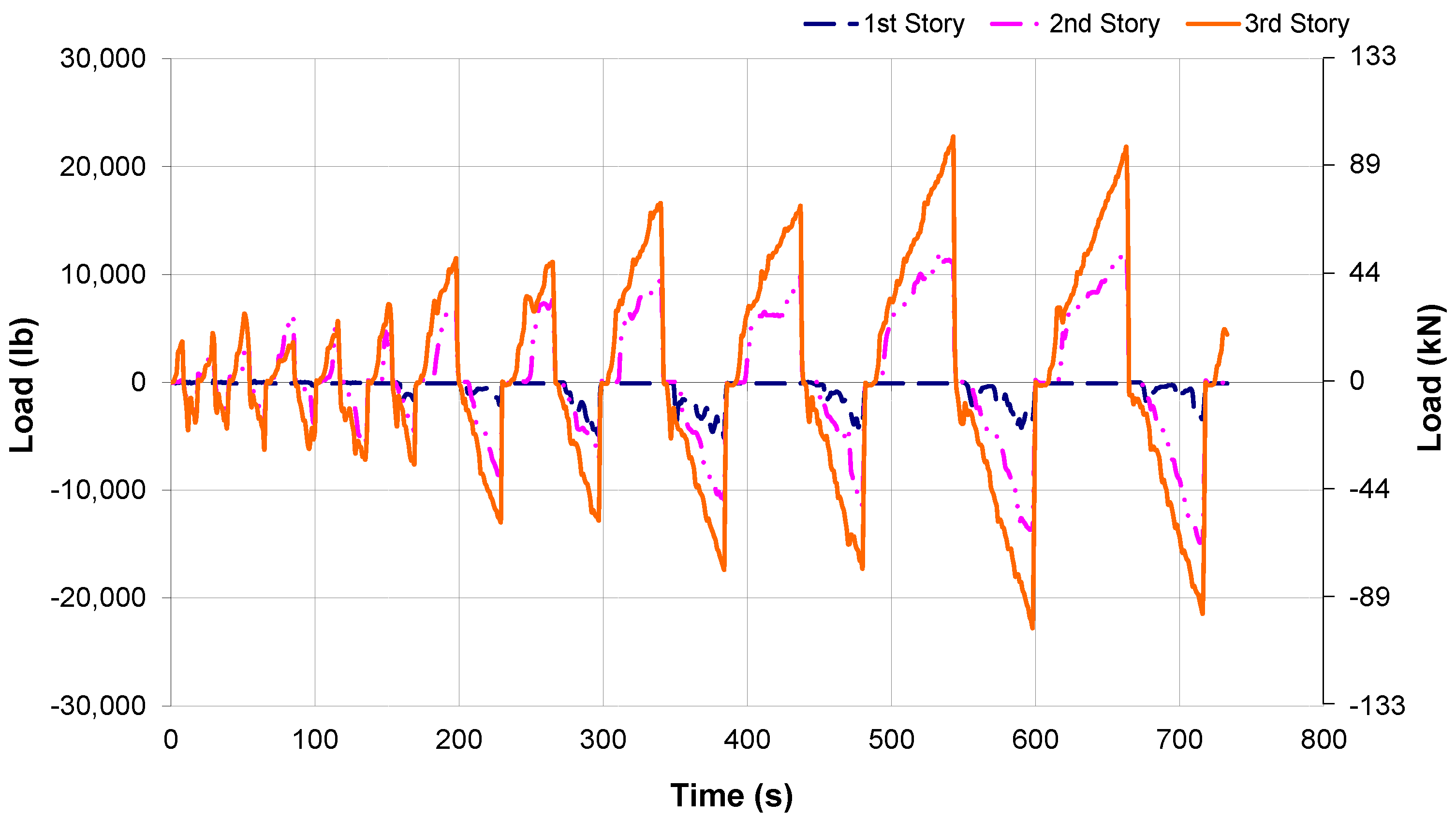
Figure 17, respectively. The target quasi-static loading protocol was followed closely throughout the full brace cyclic tests. The load histories for tests FBCT2 and FBCT4 are shown in
Figure 18 and
Figure 19, respectively. Comparison of
Figure 16,
Figure 17,
Figure 18 and
Figure 19 with
Figure 12 and
Figure 13 shows the effect of the infills on the bare frame including full brace. The load behavior during these tests was not very similar in the forward and retract portions of the load cycles. This was particularly true at the first and second stories of the test frame. Since these tests were displacement controlled, load was applied at these stories only as needed to maintain the desired displacement shape of the test frame. As with the bare frame cyclic tests, the load applied at the third story of the test frame in either displacement direction was typically higher than the loads at the first and second stories, however, a greater proportion of the total in-plane load was applied at the first and second stories of the test frame during the cyclic tests. The quasi-static loading protocol used for the cyclic tests resulted in greater loads at the first and second stories of the tests frame. This may be due to the cyclic deformation behavior of the lumber disk fuse elements after repeated cycles of damage.
Figure 16.
Full brace cyclic test FBCT2 displacement history.
Figure 16.
Full brace cyclic test FBCT2 displacement history.
Figure 17.
Full brace cyclic test FBCT4 displacement history.
Figure 17.
Full brace cyclic test FBCT4 displacement history.
Figure 18.
Full brace cyclic test FBCT2 load history.
Figure 18.
Full brace cyclic test FBCT2 load history.
Figure 19.
Full brace cyclic test FBCT4 load history.
Figure 19.
Full brace cyclic test FBCT4 load history.
After the completion of each of these tests, the brick infill panels were inspected, and no damage was observed, confirming that the lumber disk structural fuse elements worked well as seismic isolation devices. The results of these tests also show that the response of structural frames to in-plane, cyclic loads can be predetermined by placing fuse elements with different capacities at particular story levels of the frame. By using a structural fuse, the peak loads experienced by the structural frame and infill panels can be limited to acceptable levels.
3.5. Half-Brace Cyclic Tests
For the half-brace cyclic tests, the steel bracing rods on one bay of the test frame at each story level were removed in order to study the behavior of the structural fuse system with more flexible structural frames. For the half-brace cyclic tests, just like the full-brace FBCT1 and FBCT2, 25.4 mm fuse elements were used at the first story, 19.1 mm fuse elements at the second story, and 12.7 mm fuse elements at the third story level. The same quasi-static loading protocol used for the full brace cyclic tests was also used for these tests.
The behavior observed during the half-brace cyclic tests was similar to that of the full-brace cyclic tests. During these tests, cracking did not occur in the lumber disk fuse elements until the displacement at the third story of the test frame reached at least 12.7 mm. As with the full-brace cyclic tests, damage was not observed in the brick infill panels during or after the completion of the tests.
During test HBCT1 (half-brace cyclic test 1), fuse element cracking was not observed until the displacement at the third story of the test frame reached 17.8 mm. Additional cracking occurred in both displacement directions as the load history was continued and the peak displacements were increased at each story level during subsequent load steps. During this test, the greatest fuse element damage occurred in the 12.7 mm lumber disks located at the third story of the test frame.
Figure 20 shows the damage to the 12.7 mm lumber disk at fuse location 10. During test HBCT2, the first fuse element cracking occurred at a third story deflection of 12.7 mm. From this point, increased cracking occurred in the fuse elements as the quasi-static load history was continued.
Figure 20.
Cracking of 0.5 in. disk at fuse location 10 during test HBCT1.
Figure 20.
Cracking of 0.5 in. disk at fuse location 10 during test HBCT1.
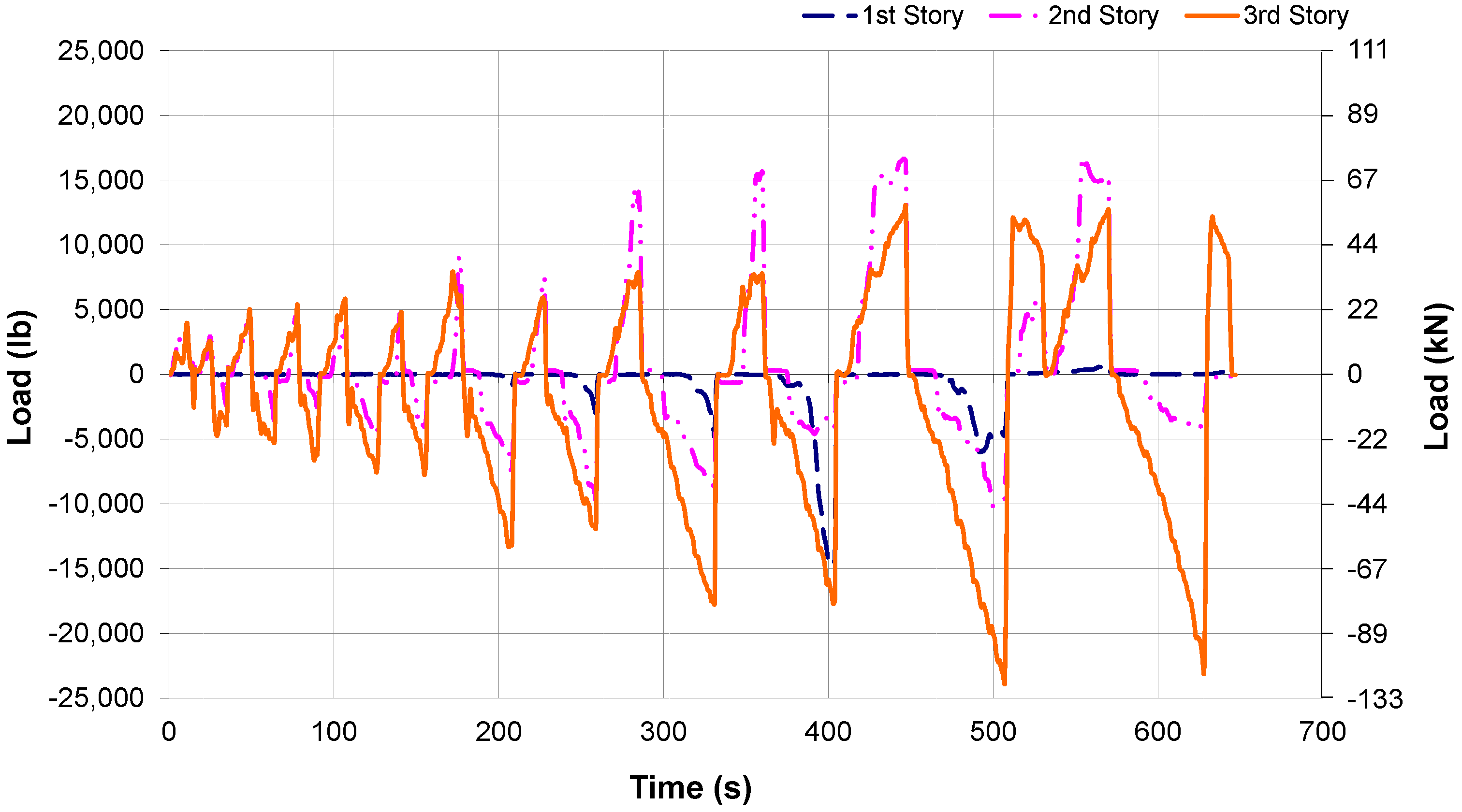
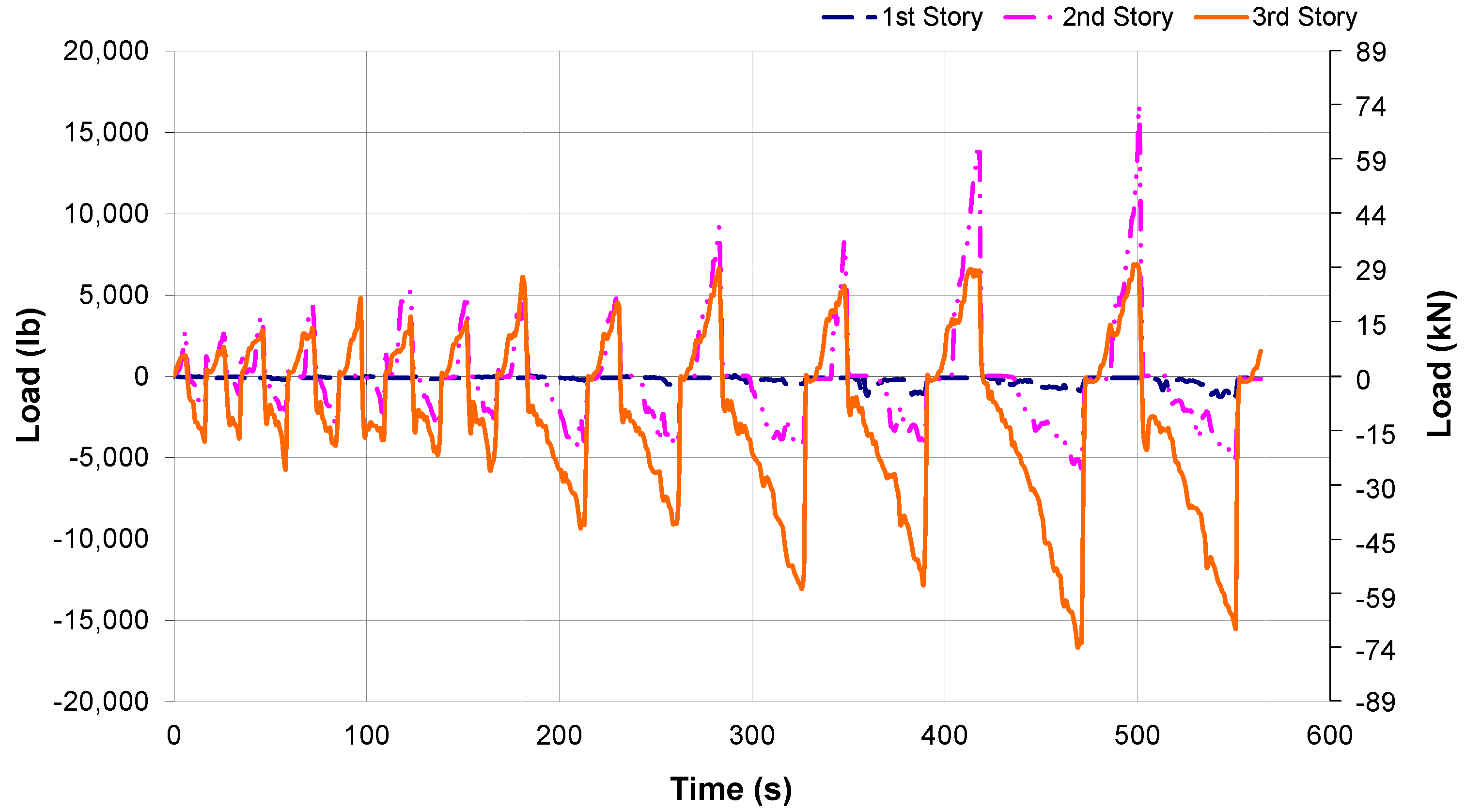
The load histories for the two half-brace cyclic tests are shown in
Figure 21 and
Figure 22. The load behavior during these tests was similar to the full-brace cyclic tests. Comparison of these figures with
Figure 13 shows the effect of the infill on bare frame with half brace. As with the full-brace tests, the loads applied to the test frame at each story level were not similar in the advance and retract directions. For these tests, very little load was applied to the test frame at the first story level. The magnitude of the loads at the second story, however, was significant. During the advance portion of several of the load cycles the load applied at the second story level was greater than the load at the third story, particularly toward the end of the tests. Similar behavior was seen for the full brace cyclic tests.
In general, the proportion of the total in-plane load applied to the test frame at the second story level was greater for the half-brace tests than the full-brace cyclic tests. This is likely due to the bracing configuration and fuse element distribution. For these tests, the weakest fuse elements were located at the third story level. As increasing damage occurred to the fuse elements during subsequent load cycles, the in-plane stiffness at the third story was reduced.
Figure 21.
Half-brace cyclic test HBCT1 load history.
Figure 21.
Half-brace cyclic test HBCT1 load history.
Figure 22.
Half-brace cyclic test HBCT2 load history.
Figure 22.
Half-brace cyclic test HBCT2 load history.
4. Parametric Tests with CMU and AAC Infill Panels
The parametric testing program was performed to evaluate the performance of the structural fuse system for use with various masonry materials. During these tests, in-plane, monotonic loads were applied in the advance direction to the two-bay, three-story steel test frame at the third story level using a hydraulic cylinder and a manually controlled hydraulic pump. These tests were performed with infill panels constructed of concrete masonry units (CMU) and autoclaved aerated concrete (AAC) blocks. The HCT infill panel specimens were not tested since they had very low in-plane strength.
4.1. CMU Monotonic Tests
For tests CMUT1 (concrete masonry unit test 1), CMUT2, CMUT5 and CMUT6, different fuse element thicknesses were used at each story level including 22.2 mm disks at level 1, 19.1 mm disks at level 2, and 12.7 mm disks at level 3. For tests CMUT3 and CMUT4, 12.7 mm disks were used at all of the fuse element locations, as shown in
Figure 8. As with the monotonic tests performed in the previous study [
28], two different bracing configurations were considered in this testing program. The full-brace configuration was used during tests CMUT1–CMUT4, while the half-brace set-up was used for tests CMUT5 and CMUT6.
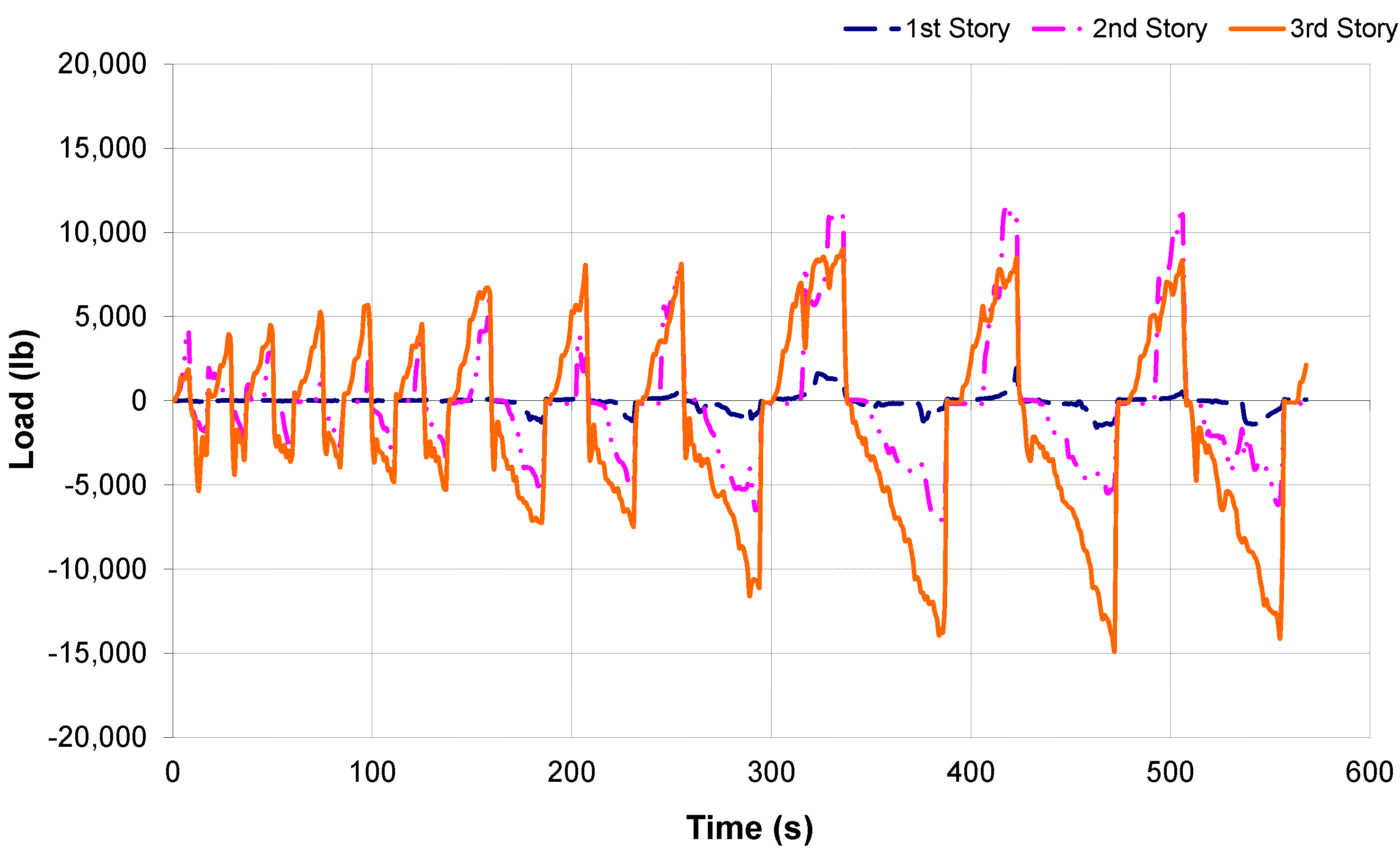
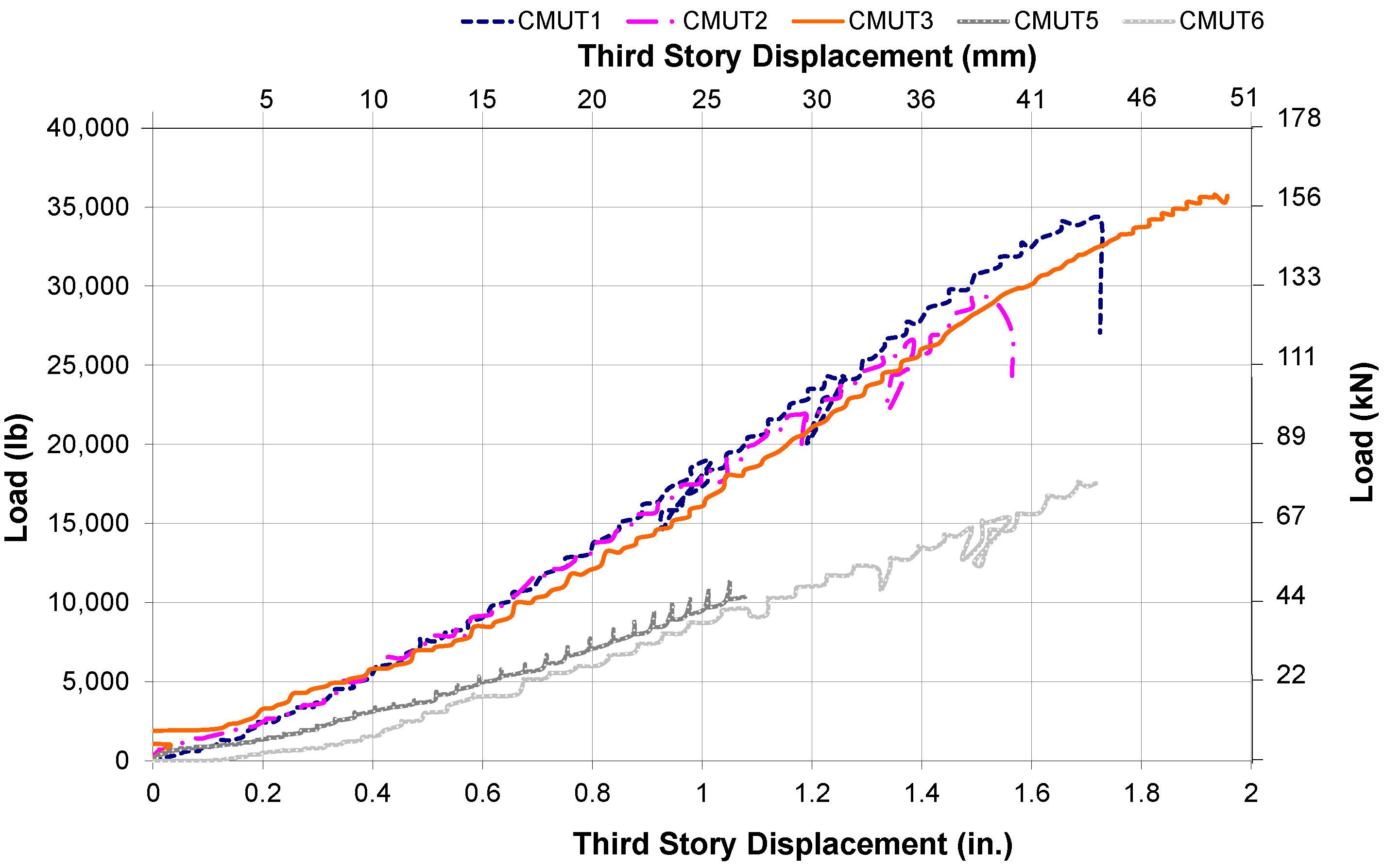
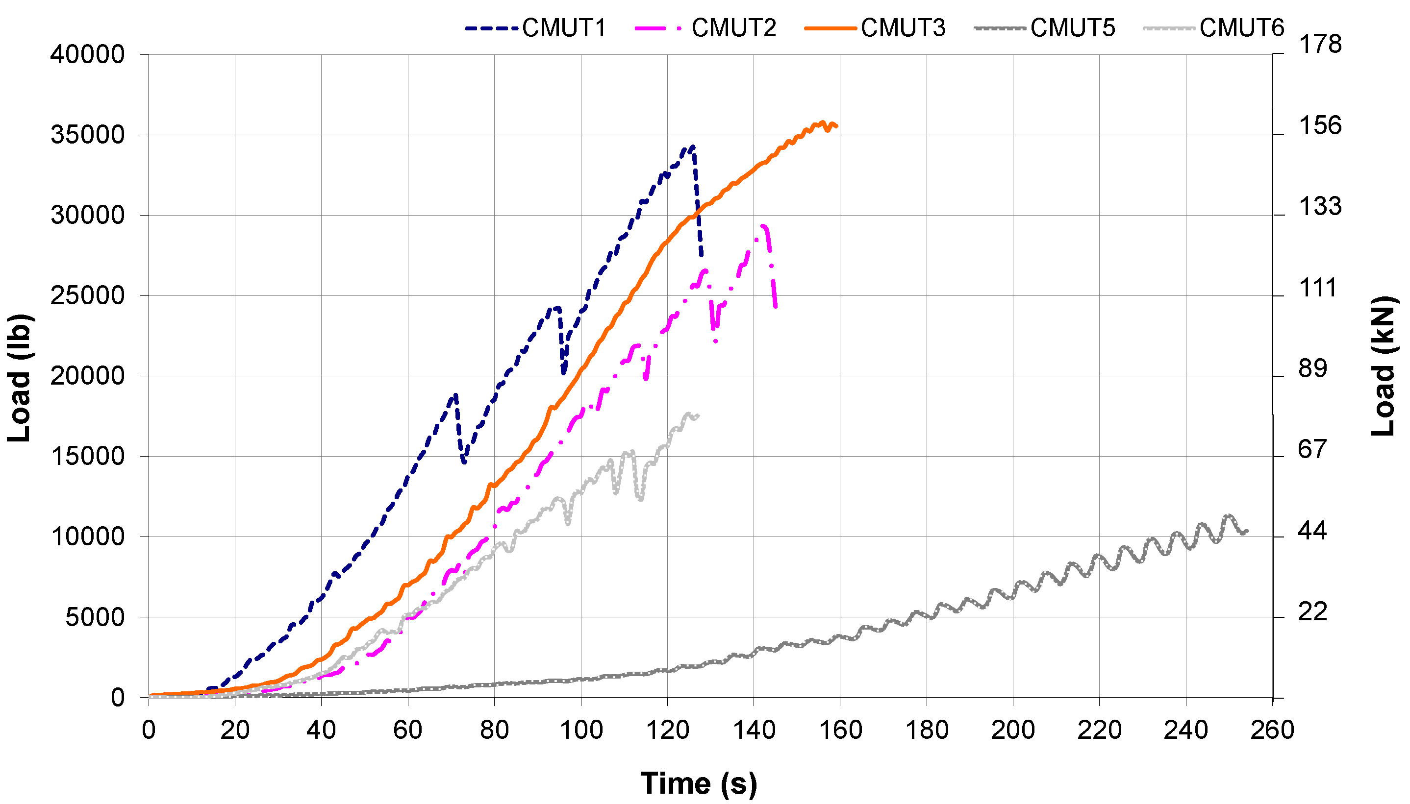
The load histories for the CMU parametric tests are shown in
Figure 23. During test CMUT4, a problem occurred with the pressure transducer, resulting in a loss of load data for this test. A plot of the load-displacement behavior for each of the CMU parametric tests is given in
Figure 24. The load-displacement behavior for tests CMUT1 and CMUT2 was very similar until the displacement at the third story reached around 27.9 mm. At this point of CMUT2, the stiffness of the test frame began to decrease. The stiffness of the test frame during test CMUT3 was slightly less than that of tests CMUT1 and CMUT2. This was expected since 12.7 mm lumber disk fuse elements were used at each story level during this test.
Figure 23.
Concrete masonry unit test (CMUT) third story load histories.
Figure 23.
Concrete masonry unit test (CMUT) third story load histories.
Figure 24.
CMUT third story load-deflection behavior.
Figure 24.
CMUT third story load-deflection behavior.
For tests CMUT1 and CMUT2, both of the fuse elements at the third story level reached their maximum capacities resulting in failure of the lumber disks and disengagement of the CMU infill panels. This behavior was expected since for these tests, the weakest fuse elements were located at the third story level. For tests CMUT3 and CMUT4, the same fuse element thickness was used at each story level. During test CMUT3, one of the fuse elements at the first story failed, while for test CMUT4, a lumber disk at the second story failed. This behavior demonstrates the importance of using an appropriate fuse element distribution in multi-story structural frames to control the failure sequence of the fuse elements and avoid a soft story mechanism.
For tests CMUT5 and CMUT6 the half-brace configuration was used, resulting in significantly less in-plane frame stiffness, as shown in
Figure 24. Although the slope of the load-displacement curve was slightly smaller for test CMUT6 than for test CMUT5, the overall load-displacement behavior for these two tests was very similar. In general the load-displacement curves for these tests were fairly linear following the first stage of behavior. During this initial stage, the bracing rods were tightening up, and the 22.4 mm dia. punching rods were just beginning to push against the lumber disk fuse elements. Toward the end of the tests, the slope of the load-displacement curves decreased due to the loss of stiffness resulting from failure of the lumber disk fuse elements and disengagement of the CMU infill panels from the in-plane load resistance.
The structural fuse system performed well during the CMU parametric tests. The CMU infill panels participated in the in-plane load resistance of the test frame up to the point where the capacity of the lumber disk fuse elements was reached. At this point, the infill panels were disengaged from the frame preventing damage to the masonry material.
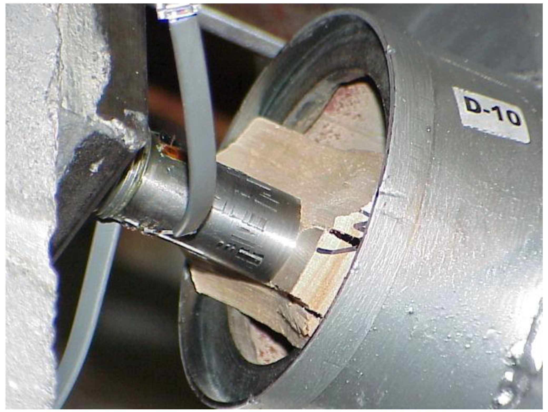
Figure 25 shows the damage that occurred to the 12.7 mm thick fuse located at the third story of the test frame during test CMUT2. The CMU infill panels were examined after each test, and no damage was observed in the walls.
Figure 25.
Damage to fuse 10 during test CMUT2.
Figure 25.
Damage to fuse 10 during test CMUT2.
4.2. AAC Monotonic Tests
For these tests, the AAC infill wall panels were positioned on the test frame. For tests AACT1 (Autoclaved aerated concrete test 1), AACT2, AACT5, and AACT6; 19.1 mm, 12.7 mm, and 6.4 mm lumber disk fuse elements were used at the first, second, and third stories, respectively. For tests AACT3 and AACT4, 6.4 mm disks were used at all of the fuse element locations. The full-brace configuration was used for tests AACT1-AACT4, while the half-brace configuration was used for AACT5 and AACT6.
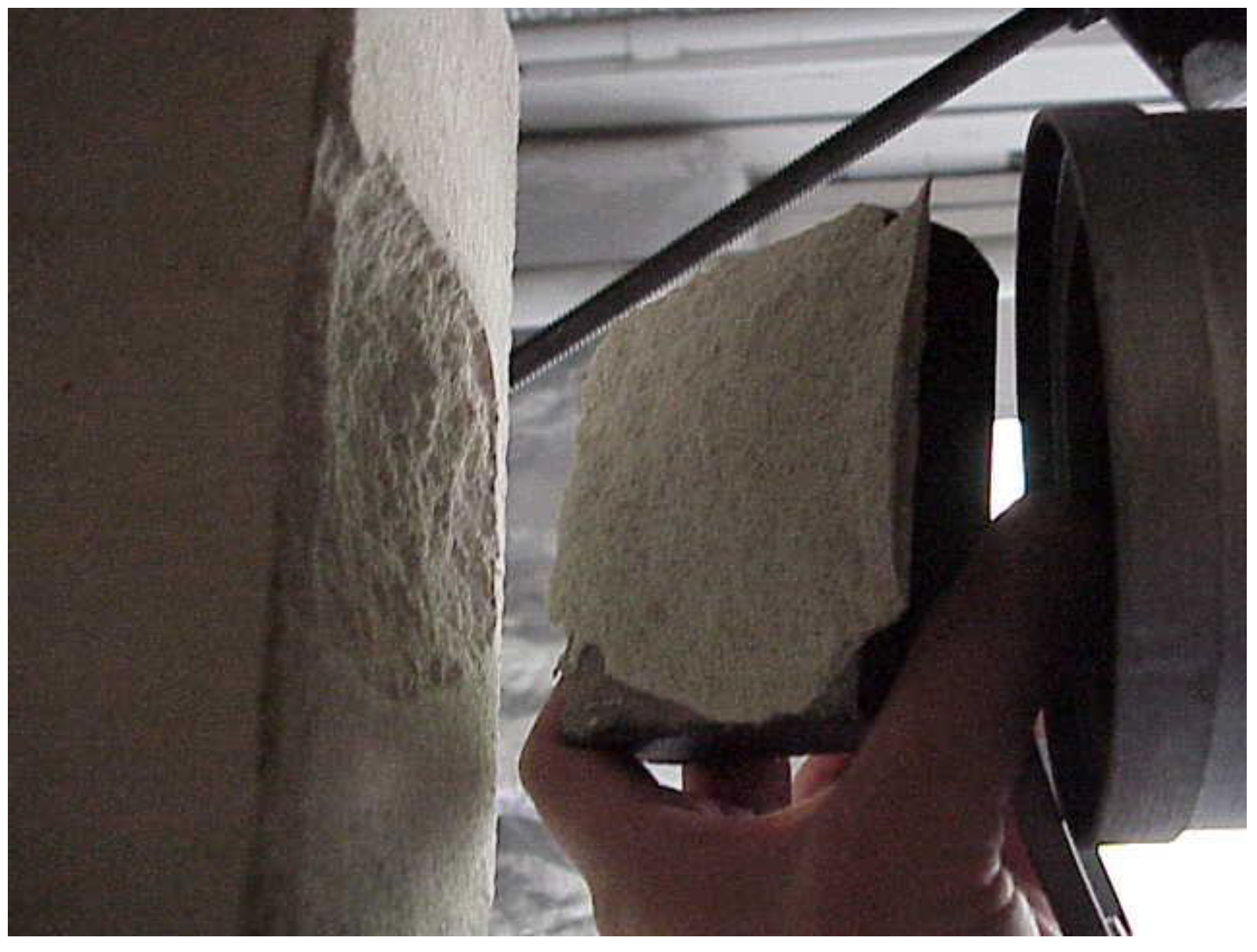
At the end of AACT1, the 25.4 mm × 76.2 mm × 76.2 mm steel bearing plates at fuse locations 6, 10, and 12 were separated from the AAC infill wall panels. This was the result of local crushing failures of the AAC material during the test. The bearing plates were reattached to the wall panels using epoxy. At the end of test AACT3, the 25.4 mm × 76.2 mm × 76.2 mm steel bearing plate at fuse location 10 also had to be re-epoxied onto the AAC infill wall panel due to local crushing of the AAC material, as shown in
Figure 26.
Figure 26.
Plate separation from AAC wall panel during AACT3.
Figure 26.
Plate separation from AAC wall panel during AACT3.
During the AAC parametric tests, in-plane shear failure of the AAC infill panels was prevented by the lumber disk fuse elements. Local crushing failure of the AAC material, however, was observed during these tests at several fuse element locations. This local material failure did not seem to cause a reduction in the in-plane resistance of the AAC panels. Repairs were required to maintain the functionality of the fuse mechanism.
The crushing damage observed during these tests was seen at fuse locations with 6.4 mm, 12.7 mm, and 19.1 mm thick fuse elements. Based on the results of the lumber disk puncture tests, the average maximum capacities of the 6.4 mm, 12.7 mm and 19.1 mm thick lumber disks were 4590 N, 10,657 N, and 19,113 N, respectively. From the in-plane destructive shear tests, the average ultimate shear capacity of the AAC panels was 56.9 kN. Based on this data, the local AAC material failures observed during these tests occurred at load magnitudes that were much less than the ultimate capacity of the AAC wall panels. To avoid this type of premature failure of the AAC material, a different fuse mechanism configuration should be considered for AAC infill panels.
During the AAC fuse element tests, the capacity of the fuse elements used at each fuse location had a significant influence on the in-plane behavior of the test frame. The contribution of the AAC infill panels to the in-plane stiffness of the test frame was successfully controlled by varying the capacity of the lumber disk fuse elements used at each story level. Using appropriate fuse element capacities in the structural fuse system is the key to preventing damage to the infill material and promoting desirable in-plane frame behavior.
5. Summary of Experimental Results
As part of this experimental program, lumber disk puncture tests were performed to study the behavior of the structural fuse elements used during monotonic and cyclic tests [
29]. The lumber disk fuse elements demonstrated consistent load-deflection behavior and failure modes with significant post peak load resistance. The relationship between disk thickness and fuse capacity was also fairly linear. Based on the ductile failure modes, consistent load-deflection behavior, low variability in capacity, and linear thickness-capacity relationship observed during these tests, the lumber disks are viable option for use as a structural fuse element.
Masonry wall panel shear tests and prism tests were performed [
29] to determine the in-plane shear strengths and compressive strengths of the masonry infill panels tested during the cyclic and parametric structural fuse system tests. Based on the results of similar tests reported in a previous study [
19], the average in-plane shear strength of the brick wall panels was 103.4 kN, and the corrected compressive strength, , was 24.8 MPa. The in-plane stiffness of these walls was 7.9 kN/mm. For the CMU wall panel specimens, the average in-plane shear strength and stiffness were 97.9 kN and 15.5 kN/mm, respectively. The corrected compressive strength of the CMU material was 18.5 MPa. The AAC walls had an in-plane stiffness of 7.0 kN/mm and an average capacity of 56.9 kN. The corrected compressive strength of the AAC material was 3.3 MPa. The HCT wall panel specimens were very brittle, and had an average in-plane capacity of only 18.7 kN, with a stiffness of 3.7 kN/mm. Based on the results of these tests, HCT infill panels should be isolated from structural frames and not relied on to carry in-plane lateral loads.
During the full brace and half brace cyclic tests, a greater percentage of the total in-plane load was applied at the first and second levels than during the bare frame tests. As discussed earlier, this was partly due to the cyclic loading protocol used for these tests. As increasing damage occurred to the fuse elements during each load step, the relative in-plane stiffness at each story level changed based on the fuse element distribution and bracing configuration. This resulted in a load distribution to the test frame that was different from what was observed during the monotonic tests. For the cyclic tests performed using the half-brace configuration, an even greater percentage of the total in-plane load was applied at the lower stories.
For building structures subject to in-plane lateral loads, the story forces are distributed to the lateral force resisting frame elements according to their relative in-plane stiffness. It is desirable to have stronger fuse elements and consequently, greater in-plane stiffness at the lower levels of the structural frame to avoid a soft story mechanism. The results of the cyclic testing program showed that having stronger fuse elements at the first and second stories of the test frame resulted in a larger percentage of the total in-plane load being applied at these levels. This behavior was not captured by applying monotonic loads at the top story level of the test frame.
For the cyclic tests where different fuse element thicknesses were used at each story level, the distribution of fuse element damage was more sporadic than for the monotonic tests reported in [
19]. In both testing programs the greatest fuse element damage was seen at the third story, where the weakest fuse elements were located. For the cyclic tests, however, significant damage was also observed at the other story levels. For the cyclic tests where the same disk thickness was used at all story levels, the greatest damage was observed in the disks at the first story level. This result was consistent with the test results presented in [
19]. Based on this observation, it is important to use higher capacity fuse elements at the lower story levels.
During the cyclic testing program the lumber disk fuse elements successfully isolated the brick infill walls from the test frame as the in-plane story forces increased. No damage was observed to the brick infill walls. The cyclic application of the loads to the fuse elements did not have a significant influence on behavior of the lumber disks. Since a quasi-static cyclic loading history was used, the effect of the loading rate on the behavior of the lumber fuse elements was not evaluated during this testing program.
The results of the parametric tests showed that the structural fuse system can be successfully used to prevent damage to infill walls constructed of various masonry materials. During these tests, the CMU and AAC infill panels participated in the lateral load resistance of the test frame and contributed to the in-plane stiffness. In-plane shear failure of the CMU and AAC wall panels was prevented by the lumber disk fuse elements. During the AAC tests, local material crushing was observed at the location of the fuse mechanism. Although this behavior did not result in brittle failure of the infill panels, it showed that local failure of the masonry material must be considered in the design of the fuse element. In addition to preventing in-plane failure of infill panels, the structural fuse system should be designed and detailed to be durable and require as little maintenance as possible.


