Article

Introduction of an Innovative Cladding Panel System for Multi-Story Buildings

by
Hathairat Maneetes
1 and
Ali M. Memari
2,*
1
Department of Rural Roads, Ministry of Transport, Bangkok 10100, Thailand
2
Department of Architectural Engineering and Department of Civil and Environmental Engineering, The Pennsylvania State University, University Park, PA 16802, USA
*
Author to whom correspondence should be addressed.
Buildings 2014, 4(3), 418-436; https://doi.org/10.3390/buildings4030418
Submission received: 22 June 2014 / Revised: 29 July 2014 / Accepted: 5 August 2014 / Published: 14 August 2014
(This article belongs to the Special Issue Seismic-Resistant Building Design)

Abstract

:
An Energy Dissipating Cladding System has been developed for use in buildings designed based on the concept of damage-controlled structure in seismic design. This innovative cladding panel system is capable of functioning both as a structural brace, as well as a source of energy dissipation, without demanding inelastic action and ductility from the basic lateral force resisting system. The structural systems of many modern buildings typically have large openings to accommodate glazing systems, and a popular type of construction uses spandrel precast cladding panels at each floor level that supports strip window systems. The present study focuses on developing spandrel type precast concrete cladding panels as supplementary energy dissipating devices that are added to the basic structural system. Through a series of analytical studies, the result of evaluating the ability of the proposed Energy Dissipating Cladding system to improve the earthquake resistance of the buildings is presented here.

1. Introduction

In conventional code-based earthquake-resistant design, the structure response to the design ground motion can be significantly damped through the action of inelastic deformation typically concentrated at the beam-column connections or specially detailed energy absorbing framing elements (e.g., shear link in an eccentrically braced frame). When properly designed and constructed, these energy absorbing elements are expected to sustain many cycles of inelastic deformation without collapse in the event of a strong earthquake. In principle, these elements would be replaced at the end of a severe earthquake event because of the presence of large plastic deformations. However, these elements, normally, are integrated parts of the structure and replacement may be difficult and very costly. Damage tolerant structures or Damage-Controlled Structures (DCS) [1] is another category of earthquake-resistant structures that rely on the action of supplemental energy dissipation mechanisms to reduce the dynamic response of the structure. However, unlike the conventional approach of strong-column weak-beam for a ductile frame, the DCS does not demand inelastic behavior from the structural frame (i.e., the frame remains essentially elastic). The inelastic demand is limited to the supplemental energy dissipating devices that are added to the structural system but are not an integrated part of the structure [2]. As a result, the integrity of the structure or building is expected to remain essentially intact, even after an earthquake event. Furthermore, these “disposable” supplemental energy dissipating devices could be readily adjusted or replaced. A new type of DCS, known as the Energy Dissipating Cladding System (EDCS), was recently developed by Maneetes [3] that is capable of functioning both as a structural brace, as well as a source of energy dissipation, without demanding any inelastic action and ductility from the basic lateral force resisting system. This paper briefly introduces the EDCS component and presents the results of a study that analytically evaluates the appropriateness of using such a system as supplementary energy dissipating devices for seismic design of certain types of buildings.

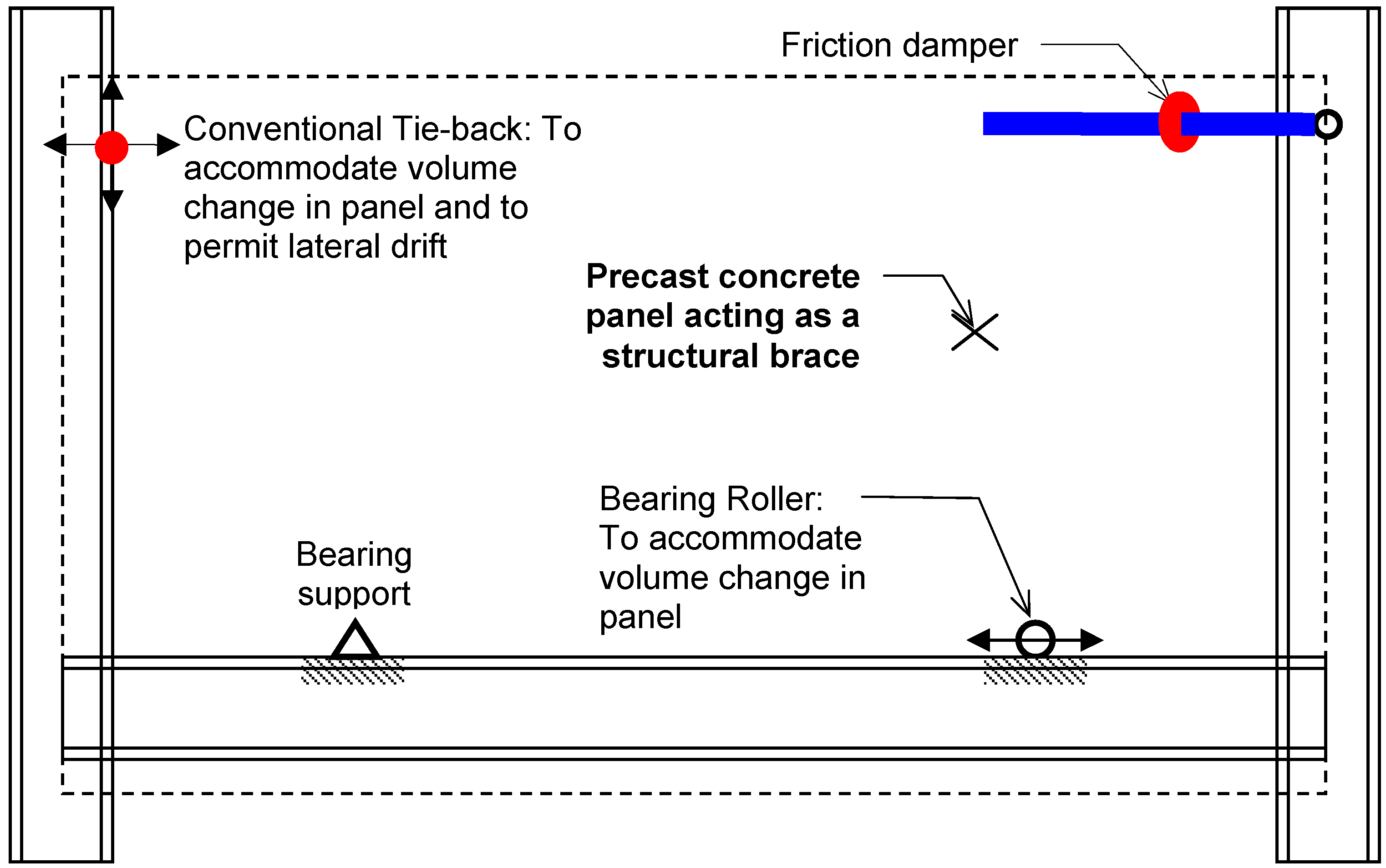
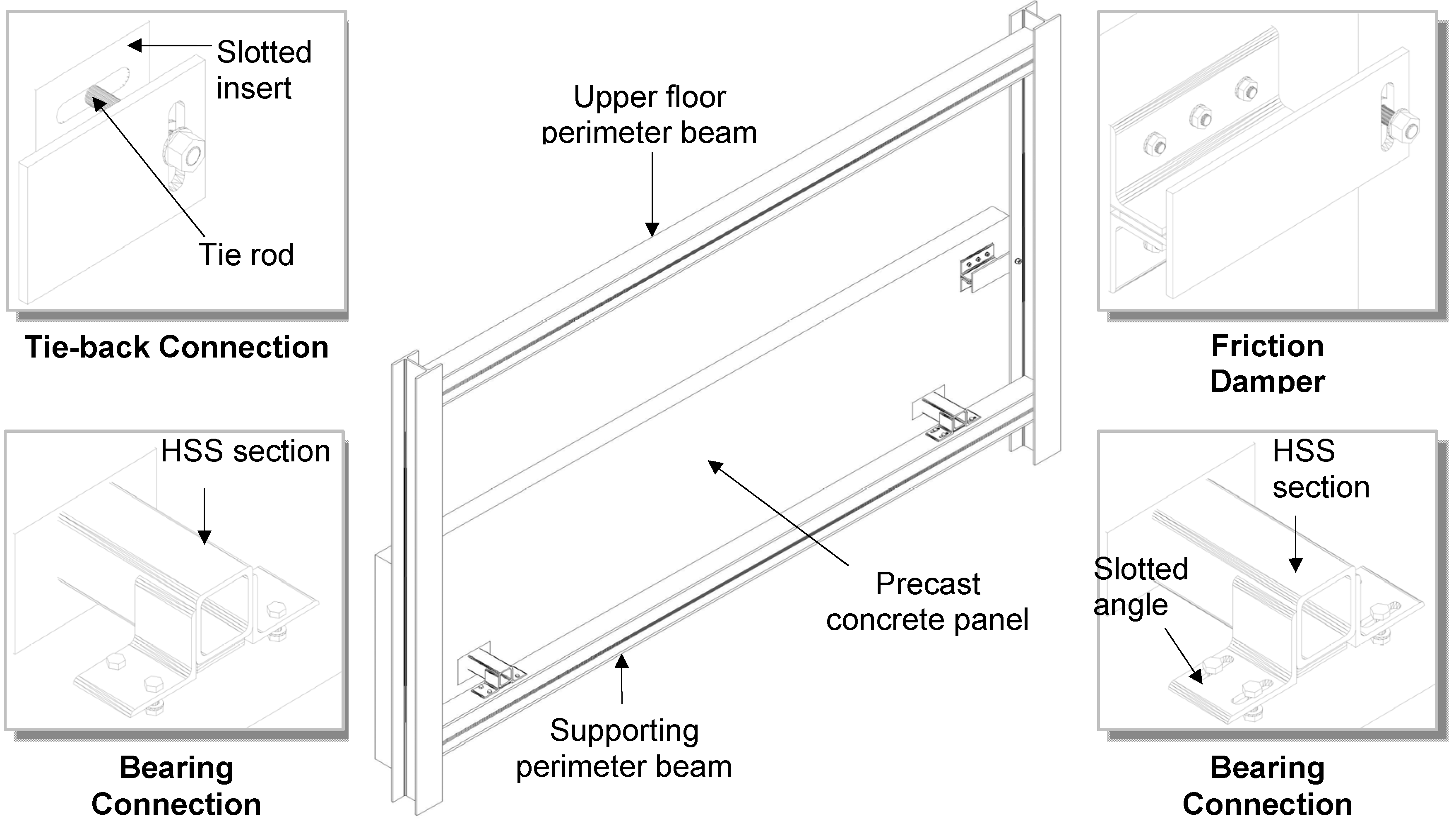
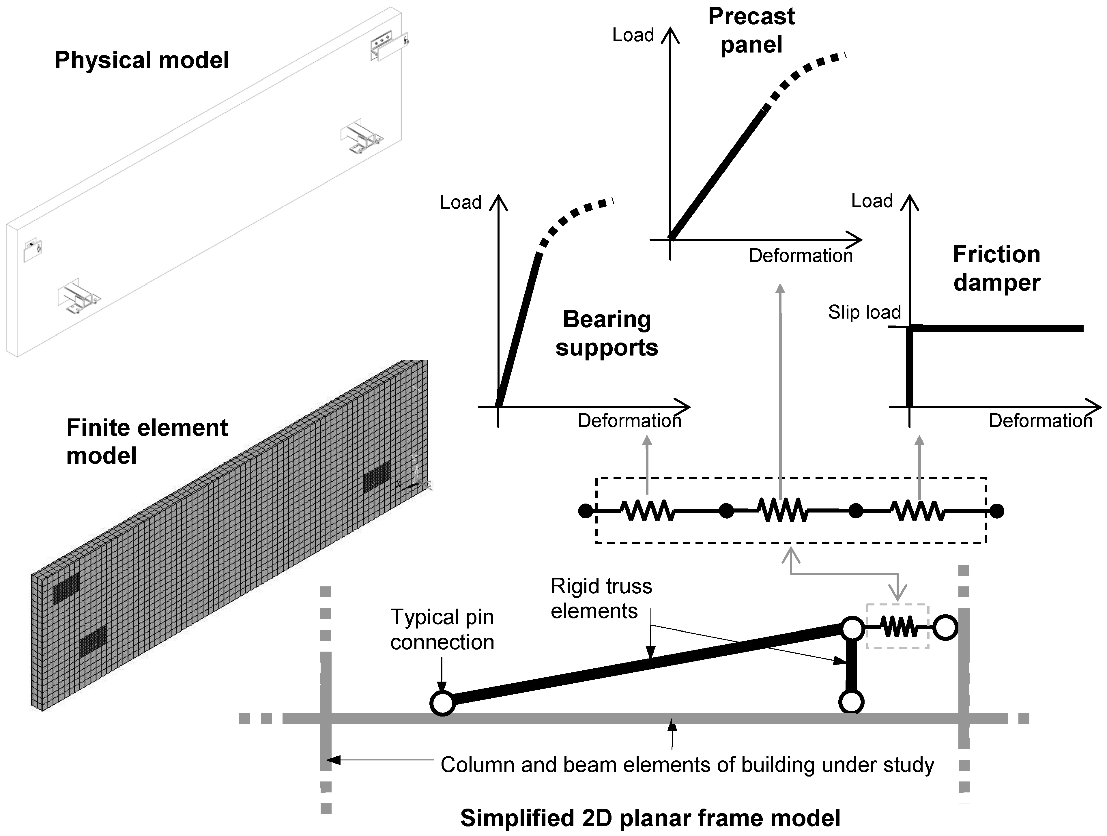
2. EDCS Design and Mathematical Modeling

Figure 1 and Figure 2 show the schematic view and sketches of various parts of the proposed EDCS that was developed to exploit the cladding-structure interaction while minimizing damage to the concrete panels. Connection details (e.g., tie-back, bearing connections) typical of conventional precast cladding system are employed with the aim of reducing production and installation cost. For general information on seismic performance of cladding panels and some details, the document published by the Whole Building Design Guide [4] is useful. One of the support bearing connections is bolted (and welded) to the supporting beam, while the other bearing connection is restrained from uplift but is detailed (through the use of slotted connection) to translate laterally to accommodate volume changes in the panel. As shown in Figure 1, the tie-back connection is placed at the upper left corner, but, in Figure 2, the tie-back connection is not seen on the perspective view as it would be behind the column shown. The precast concrete panel is designed to function as a rigid (elastic) brace during low intensity earthquake motions. Under moderate or high intensity seismic motions, the in-plane forces developed in the cladding panel would exceed the design slip load of the Slotted Bolted Connection (SBC) friction damper (Figure 2), causing it to slip horizontally and dissipate part of the building input energy. In this regard, the friction damper has an important function of limiting the maximum load that can be transferred to the concrete panel. The friction damper is incorporated as part of the connection between the supporting column and the cladding panel. The stiffness and strength characteristics of the EDCS have been investigated in detail by Maneetes [3], based on a series of Finite Element Analysis (FEA) supported with classical structural analysis [5]. The result is a simplified two-dimensional assemblage of truss and spring elements, which can be readily incorporated into the analytical model of a building under consideration (Figure 3). Not much additional and new research has been done recently on this topic. However, one recent study has developed computer modelling of cladding panels used in a full scale testing study [6].
Figure 1. Schematic View of the EDCS.
Buildings 04 00418 g001
Figure 2. Components of EDCS.
Buildings 04 00418 g002
Figure 3. Mathematical modeling approach of EDCS.
Buildings 04 00418 g003

3. Performance of EDCS in Reference Structures

The first step in assessing the effectiveness of the proposed EDCS is to incorporate it in mathematical models of buildings that have been laboratory tested, modeled, and with detailed test data available for comparison. Three one-quarter scaled nine-story test structures from the research program by Aiken and Kelly [7] were chosen and used for this purpose. Figure 4a shows the first test structure, referred to here as the Ordinary Model Frame (OMF). The model’s first story is 1.2 m (4 ft) high with the upper stories at 0.9 m (3 ft) high. The bays are 1.52 m (5 ft) and 1.98 m (6.5 ft) wide at the center and ends, respectively. The structure is approximately 8.53 m (28 ft) high by 5.49 m (18 ft) wide and with an aspect ratio of 1.56. Beams and columns are W6 × 8.5 and W4 × 13 sections, respectively. The structure has three bays in the direction of testing and one bay of 1.83 m (6 ft) wide in the lateral direction. The second test structure (Figure 4b) is a Concentrically-Braced Frame (CBF) formed by adding chevron bracings, consisting of 38.1 mm × 38.1 mm × 6.4 mm (1½ in. × 1½ in. × ¼ in.) double-angles at the bottom level and 25.4 mm × 25.4 mm × 6.4 mm (1 in. × 1 in. × ¼ in.) double-angles at the remaining levels, to OMF, while the third structure (Figure 4c) is the same as CBF model but with supplemental Sumitomo cylindrical friction dampers added to the connections between the bracings and the beams and referred to here as the Friction Damper (FD) model. The cylindrical friction damper device was originally developed by Sumitomo Metal Industries, Ltd., Japan, as a shock absorber in railway application. In these devices, the friction force is generated through the sliding of copper alloy friction pads with the inner surface of the steel cylinder.
Figure 4. Structures tested by Aiken and Kelly [7]. (a) OMF; (b) CBF; (c) FD. Reproduced with permission from [7]. Copyright 1990 Pacific Earthquake Engineering Research Center.
Buildings 04 00418 g004

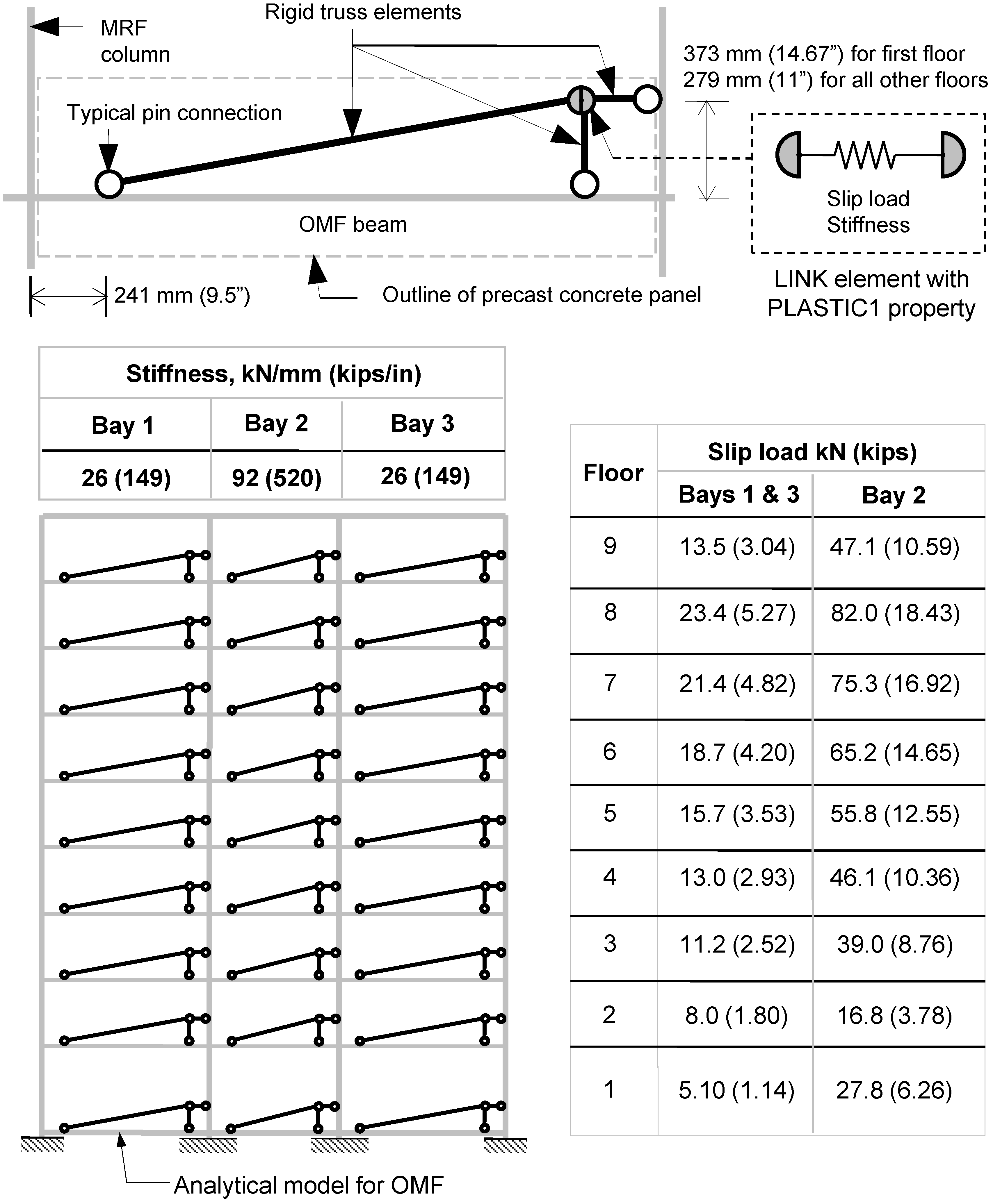
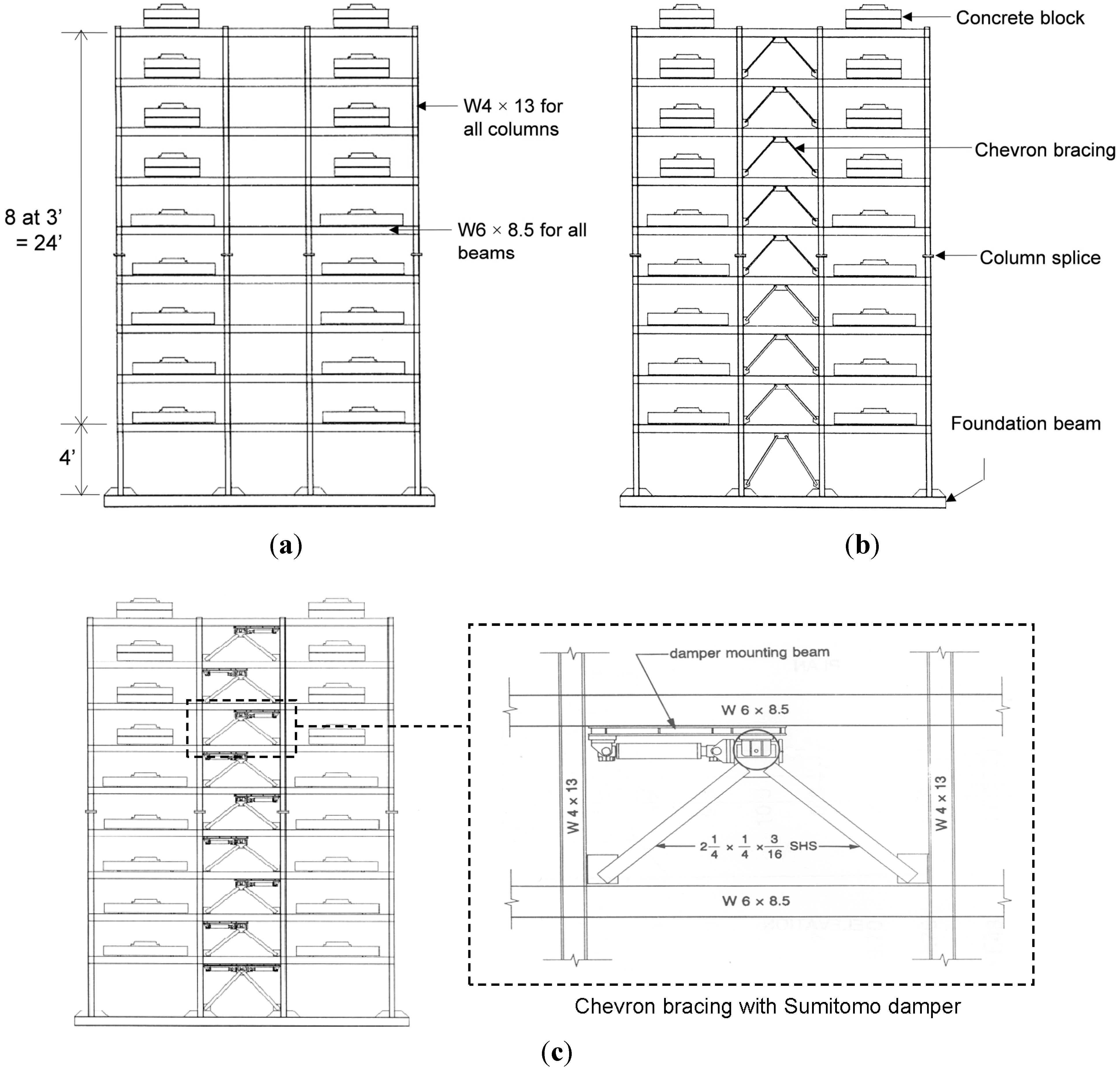
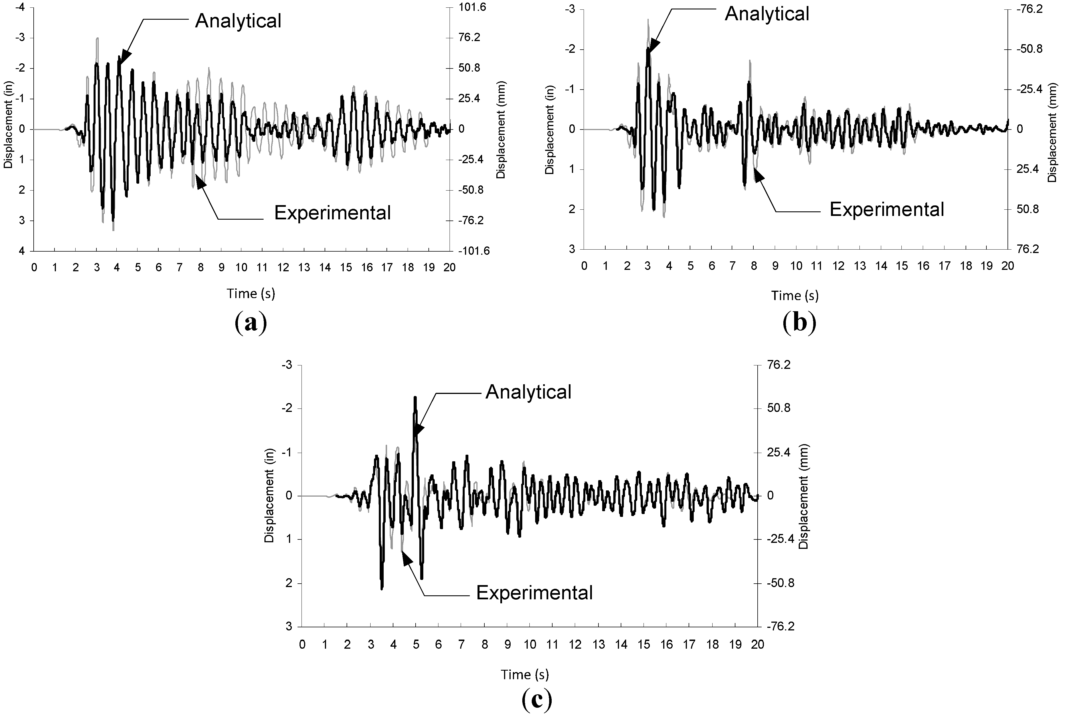
3.1. Modeling of Reference Frames

In this study, mathematical models of the three test frames were developed as two-dimensional planar frames in this study using ETABS [8], which allows modeling doubler plates at the beam-column panel zone joints by simply specifying the doubler plate thickness. All frame elements were modeled as continuous classical beam-column elements with 25% rigid-end offsets applied to the ends of all the frame elements to account for the reduction of length due to the finite depth of the beam-column joints. This 25% factor was determined through modal frequency correlations [3]. Additional lump masses of 44.5 kN (10 kips) weight were also distributed to the four beam-column joints at each story per test setup in order to satisfy the similitude requirements consistent with the test structure. The significant shake table-structure interaction (due to table pitching) was also carefully modeled as per Aiken and Kelly’s [7] recommendations. To model the Sumitomo friction devices and braces for the FD model, a horizontal rigid truss element, that was only capable of resisting axial load and deformation, connects the apex of the braces to the column near the column-beam connection. By specifying a large cross-sectional area (6.4 × 106 mm2 (104 in2)) for the rigid truss elements, the horizontal deformation was restricted to the friction damper, modeled here by the ETABS LINK element with PLASTIC1 properties, which include a sufficiently high elastic stiffness of 1.8 × 10⁵ kN/mm (1 × 10⁶ kips/in) that was specified to reflect the nearly perfectly plastic behavior of the friction damper. The PLASTIC1 property in ETABS used is based on the hysteretic uniaxial plasticity behavior suggested by Wen [9]. Other details of the mathematical models and related properties can be found in [3].
The accuracy of the ETABS frame models was first investigated by a series of modal analyses. The natural frequencies (first three modes) of the mathematical models [3] agreed well (between −0.2% to 10.9%) with the experimental values reported by Aiken and Kelly [7]. Next, the dynamic response of each ETABS frame model was investigated using two historical ground motions consisting of (1) Imperial Valley, 1940 El Centro, S00E component with a Magnitude of 6.95 on the Richter scale and 0.313 g peak ground acceleration (PGA), and (2) Kern County, 1952 Taft, Lincoln School S69E component with a Magnitude of 7.36 and PGA of 0.178 g, which were also used in the shake-table experiment. All ground motion data used in the present study were obtained from Pacific Earthquake Engineering Research Center (PEER) Strong Motion Database. The digitized accelerograms provided by PEER differ slightly from the original shake-table signals used in Aiken and Kelly’s [7] experiments due to different correction filters used by the providers of these data, and this caused some differences in the result of the analysis (based on the ETABS model described earlier) in this study [3] and those resulting from shake-table experiments [7]. With the table-interaction included in the mathematical model, the correlations are significantly improved. Except for the Taft ground motions, the analytical predictions for the peak roof displacements closely matched those from the experiment. However, it was found that the disparity between the predicted and actual peak roof accelerations were as high as 120% for the Taft ground motion, but significantly less for the El Centro ground motion. The peak roof displacements for both ground motions, however, agreed much better (than peak roof acceleration), with difference less than 25%. In particular, the peak roof displacement time histories showed remarkably good correlation as shown in Figure 5 for OMF and FD. As the PEER accelerogram used in the present study differed slightly from the excitation signal used in the Aiken and Kelly [7] shake-table experiments, the close time-history correlation obtained indicates the validity of the (ETABS) mathematical models to represent the actual test structures and conditions.

3.2. Performance of EDCS in OMF and FD Models

The ETABS frame models for the OMF and FD (Figure 4) were used to study the performance of EDCS. Fixed support conditions were assumed (Figure 6) for all models in the comparative study, which permit a common basis for comparison without introducing additional complication arising from the table-structure interaction. Details of the comparative study can be found in [3]; in this section mainly the results that relate to the equivalent damping provided by EDCS are discussed. The modeling approach for the EDCS was similar to that for the (Sumitomo) friction damper in the FD model. As shown in Figure 6, each EDCS was modeled with three rigid truss elements and a nonlinear LINK element. The truss elements were oriented as shown to model the correct directions of the forces exerted by the EDCS connections on the building frame elements. These truss elements were also specified with a high axial rigidity to limit horizontal deformation to the LINK element only. Except for the stiffness and slip load (i.e., yield strength), the specification of the ETABS LINK element is identical to that used for the Sumitomo friction dampers in the FD ETABS model. The stiffness values were estimated using the method proposed by Maneetes [3] that took into account the contribution from the precast concrete panel and the connections, and scaled down by a factor of 4, based on stiffness similitude rule to reflect the one-quarter scale of the test model. The stiffness value and slip load for each bay are computed based on two panels, consistent with the configuration of the test models of Aiken and Kelly [7]. The same stiffness value was used for the same bay width, while the same slip load was applied to all three bays at the same floor level. The stiffness of the EDCS at the outer bay is about 3½ times that of the interior bay due to the difference in bay width. The slip load distribution was determined by maximizing the energy dissipation for each panel. A total of 18 LINK properties were necessary to cover the different combinations of stiffnesses and slip loads.
Figure 5. Roof time-histories for OMF and FD. (a) OMF Under El Centro; (b) FD Under El Centro; (c) FD Under Taft.
Buildings 04 00418 g005
Figure 6. Analytical model of OMF with EDCS.
Buildings 04 00418 g006
In addition to the two ground motions used previously, a third historical ground motion, the 1994 Northridge earthquake (LA, Century City CC North, N90E component with a Magnitude of 6.05 and PGA of 0.26 g) was chosen to reflect a more modern record. From each earthquake ground motion, three levels of intensity were generated corresponding to high, moderate, and low zones of seismicity, resulting in a total of nine ground motions. This was accomplished by amplitude-scaling of the original earthquake records using the ASCE 7-05 [10] procedure for two-dimensional seismic response history analysis. For the three-bay structure considered, the FD performed significantly better than the OMF with EDCS. The EDCS improved the seismic performance of the bare frame (OMF) with up to 30% reduction in peak roof displacement but at a lesser extent than FD due to smaller deformation at one-third height configuration. However, as pointed out by Aiken and Kelly [7], the excellent performance of the proprietary Sumitomo friction dampers comes with a (cost) premium. Based on time-history analysis of the models, comparison of the OMF with EDCS peak roof displacement profile with that from the OMF with different amount of viscous damping (Figure 7), showed that the equivalent damping offered by the EDCS is about 7.3%. The present OMF model was specified a 1.0% viscous damping and hence the EDCS added about 6.3% of equivalent viscous damping. This may not appear to be large. However, it should be realized that the structure considered thus far has only three bays. The energy dissipating capability and true benefit of the present EDCS would be realized for buildings with realistically more bays. Further optimization of the slip load distribution may also result in increased energy dissipation. The performance of the EDCS was then studied for a 20-story building frame and is discussed in the next section.
Figure 7. Equivalent modal damping of supplement EDCS.
Buildings 04 00418 g007

4. Building Case Study

The analytical results of the one-quarter scale 9-story frame suggested that the EDCS was capable of improving the seismic performance of the steel moment frame under strong ground motions. The application of the EDCS on a full-scale analytical building frame is illustrated in this section. In modeling the building, it was conservatively assumed that the moment frame was not expected to contribute to the inelastic demand when the model is subjected to the design earthquake. Such an approach may be specified by building owner or building codes for buildings designated as facilities representing a large hazard to the human life in the event of collapse (e.g., school facilities, detention facilities) or as essential facilities (e.g., police stations, hospitals). The approach could also be a retrofit solution to existing buildings with limited inelastic capacity. The EDCS could be incorporated into special ductile frames (e.g., intermediate moment frame or special moment frame) where the inelastic responses and the energy dissipation mechanisms are provided by both the framing elements and the EDCS. In this case, the inelastic actions of the framing elements, in addition to the EDCS, must be explicitly accounted for in the mathematical modeling. This could be achieved with specialized finite element analysis software that can explicitly model the nonlinear hinges of both steel and concrete elements. Such modeling was beyond the scope of the present study. Here, all moment frames were modeled in ETABS to behave elastically under the design ground motions, while all inelastic deformation and hysteretic energy dissipation were limited to the EDCS.

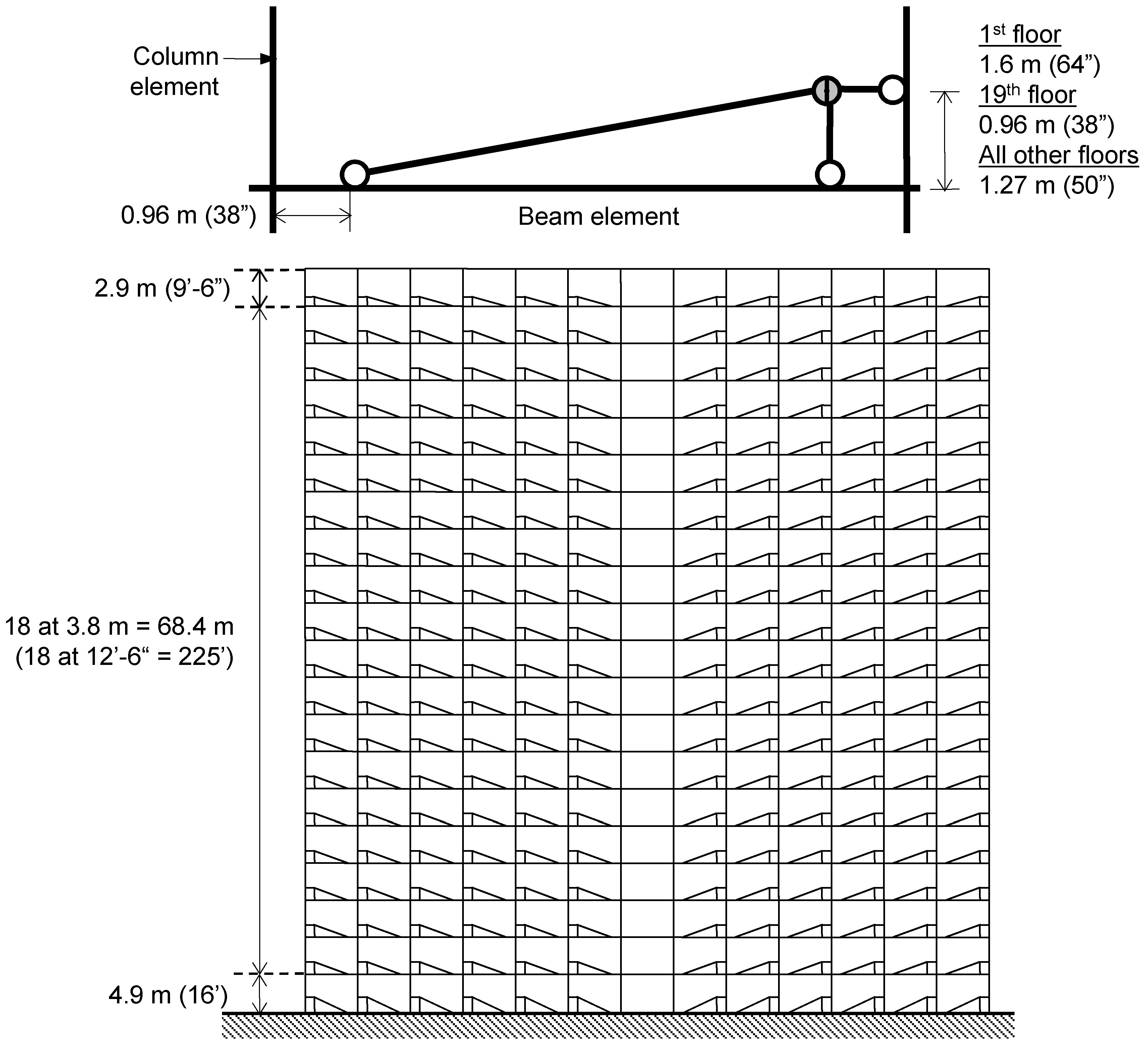
4.1. Building Description

The building studied is a 20-story steel moment frame building adopted from an office building originally investigated by Goodno et al. [11]. The building, which is located in San Francisco Bay area, was reported to have been constructed almost a decade before the devastating 1989 Loma Prieta earthquake. In their analytical studies, Goodno et al. [11] investigated the use of advanced cladding connectors to improve the seismic performance of a contemporary building. The study showed that up to 16.8% reduction in steel weight (as a result of using smaller framing sections), as compared to the baseline building design, could be achieved with the advanced connectors. The building measures approximately 81 m (267 ft) by 28 m (92 ft) on plan, and is about 76 m (251 ft) high. The building did not possess any form of irregularities on plan or elevation. Except for the ground and last floors that measured about 4.9 m (16 ft) and 2.9 m (9 ft 6 in.), respectively, each floor is 3.8 m (12 ft 6 in.) high. As part of the floor system, 140 mm (5.5 in.) thick composite floor decks were installed and approximately one-third height 114 mm (4.5 in.) thick architectural spandrel type precast concrete cladding panel covered the entire building facade. In the longitudinal direction, the 13-bay perimeter frames were designed as special moment frames and made up the Lateral Force Resisting System (LFRS). In the three-bay wide transverse direction, combinations of special moment-resisting frames and concentrically-braced frames were designed to resist the lateral loading. The analytical studies of Goodno et al. [11] were limited to two-dimensional analysis of the longitudinal LFRS. In view of the limited information available, only the longitudinal 20-story, 13-bay moment frame was investigated in this study. In the following discussion, the finite element model developed to represent the longitudinal 20-story, 13-bay moment frame is designated as BMF.

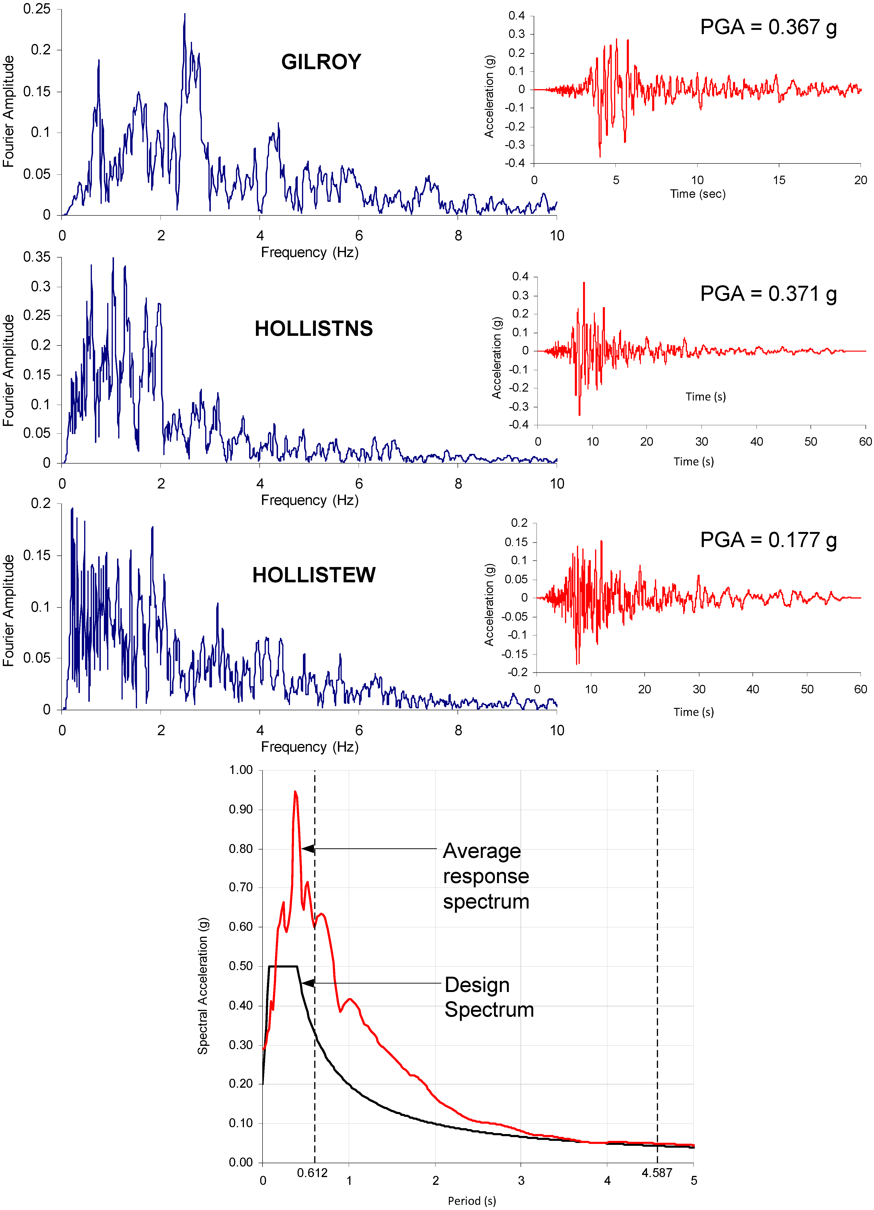
4.2. Design Approach

The BMF was designed as an ordinary moment frame for Seismic Use Group I and under SDC C, in accordance with conventional seismic-resistant design procedure in ASCE 7 [10] adopted by International Building Code [12]. More ductile intermediate moment-resisting frame or special moment-resisting frame could have been used for the BMF. As mentioned earlier, the design approach of EDCS assumes that the moment frame remains essentially elastic and all inelastic actions are provided by the supplemental energy dissipating devices, in this case, the EDCS. As a result, the BMF was designed as an ordinary moment frame, which is assumed to have negligible inelastic rotation capacity [13]. But designing ordinary moment frame for SDC D or higher is not practical, as it would result in significantly heavier sections. Therefore, the building was assumed to be located on a site where SDC C would apply. Linear static and elastic time-history methods, with a response modification factor of 3.5, were used in the design of the BMF; the Equivalent Static Lateral Force Method [9] was used to establish the code-specified minimum base shear. The seismic design parameters used for design of the BMF are listed in Table 1.
Table 1. Seismic Design Parameters.
ParameterSymbolValue
Seismic importance factorI1.0
Design short period (0.2 s) ground accelerationSDS0.50 g
Design long period (1.0 s) ground accelerationSD10.20 g
Calculated fundamental periodT3.09 s
Response modification factor (for linear procedures only)R3.5
Reliability/redundancy factorρ1.0
System overstrength factorΩο3.0
Drift amplification factor (for BMF)CD3.0
The BMF was modeled in ETABS as a fixed-supported building consisting of 260 beam elements and 280 column elements. To complement ETABS automated design capability, the columns and beams were divided into a total of 32 design groups corresponding to the location of the elements at the start of the design process. The purpose of grouping the elements was to reduce the number of different steel sections required and to avoid odd variation of the steel section either at each floor or over the building height. It was assumed that the office building was not intended for storage purpose and the live load was not considered in the seismic weight. In addition to the dead load acting on the moment frame, lumped masses were assigned to all the beam-column joints to account for the tributary effective seismic weight at each floor. Lumped masses of 18,416 kg (0.105 kips-s2/in) and 19,549 kg (0.112 kips-s2/in) were added to the joints at the roof level and every floor level, respectively. For the final design, a total of 4 and 18 different W-shapes were used for the beams and columns, respectively. The total steel weight of the BMF was 2544 kN (572 kips), which represented only 0.6% of the estimated effective seismic weight. The total weight of the original special moment frame analyzed by Goodno et al. [11] was 4746 kN (1067 kips) due to higher earthquake loading. The details can be found in Maneetes [3].

4.3. Design Analysis of MFEDCS

The 20-story moment frame with the added EDCS (MFEDCS) is shown in Figure 8. The EDCS’s were arranged to maintain the geometrical symmetry of the structure. The MFEDCS model was created in ETABS the same way as that described previously for the nine-story moment frame of Aiken and Kelly [7], i.e., the same modeling strategies of the friction damper and EDCS were used in ETABS. Cladding panels with 114 mm (4.5 in.) thickness were installed in the as-built building. In the study discussed here, however, 152 mm (6 in.) thick precast concrete cladding panels were specified. The calculated panel heights were 2.0 m (78 in.), 2.6 m (104 in.), 2.3 m (90 in.) for the 20th floor, 1st floor and all other floors, respectively. The panel stiffness for different floor heights was estimated based on the simplified method proposed by Maneetes [3]. Although three different stiffness values could have been used for three different floor heights, the lowest value of 169 kN/mm (967 kips/in) was conservatively assigned to the elastic-perfectly plastic spring for all EDCS units. Different slip loads were studied as elaborated below.
Figure 8. MFEDCS model.
Buildings 04 00418 g008
Nonlinear time-history analysis was carried out to evaluate the nonlinear response of the EDCS. The three ground motions of GILROY, HOLLISTNS, and HOLLISTEW recorded at three different stations during the 1989 Loma Prieta earthquake were selected for the time-history analysis as shown in Figure 9. The dominating frequencies of these three ground motions varied over a wide range from 0.2 to 2.5 Hz, which coincide with the natural frequencies (0.16 to 1.16 Hz) of the structures under consideration. The HOLLISTEW ground motion has the lowest PGA but its dominating frequencies (about 0.2 to 0.5 Hz) matched very closely with the fundamental frequencies of the MFEDCS model. Hence, this low amplitude ground motion is expected to have the greatest damage potential on the moment frame at any given PGA. All ground motions were obtained from PEER. The three ground motions were scaled with the average of the three ground motion response spectra exceeding the target design spectrum between the period limits of 0.62 s and 4.63 s. Instead of a single amplitude scaling factor for the suite of ground motions, three different factors were used to achieve similar magnitude building base shears from the three ground motions. This also resulted in the average response spectrum matching closer to the design spectrum than that compared to the case where a single scaling factor was used. The GILROY, HOLLISTNS, and HOLLISTEW ground motions were scaled and labeled as LOMAP1, LOMAP2, and LOMAP3, respectively.
Figure 9. Time-histories, FFTs and response spectrum of selected ground motions.
Buildings 04 00418 g009
The nonlinear time-history analyses were performed for five slip loads of 4.5 kN (1 kips), 22.2 kN (5 kips), 44.5 kN (10 kips), 89.0 kN (20 kips) and 133.5 kN (30 kips) to establish the appropriate slip load level. A single slip load value was found to be adequate for the entire building. With a single slip load, the analytical results revealed that only a number of EDCS at the 18th and 19th floors did not develop adequate hysteretic loops (hence low energy dissipation) for one or two of the design ground motions. However, this did not warrant the need to optimize the slip load distribution since actual earthquake ground motions would vary considerably in amplitude and frequency content. As shown in Figure 10, increasing the slip load increases the stiffness of the moment frame, thereby attracting more story shear (especially at the lower stories) while reducing the peak interstory drift.
The selection of the slip load could be based on any one or combinations of the following criteria: (1) the friction dampers in the EDCS should not activate or slip under the design wind load; (2) each framing element supporting the EDCS should not exceed its capacity; and (3) the total energy dissipation in the EDCS should be maximized. Criteria 1 would normally set the lower bound for the slip load. For example, assuming a basic wind speed of 136 km/hr (85 mph) for the West Coast regions of the United States and Exposure B, the maximum equivalent quasi-static design wind load (at the roof level) based on IBC 2006 [12] was estimated to be 111 kN (25 kips). If this load was distributed equally to the EDCS components, the wind load exerted on each EDCS should not be more than 9 kN (2 kips). Therefore the minimum slip load of the EDCS should not be less than this value. Criteria 2, on the other hand, would place a cap on the design slip load. The nonlinear time-history design results revealed that for slip load between 22 kN (5 kips) to 89 kN (20 kips), the member sizes used for the BMF were generally adequate. As the slip load reduced to 4.5 kN (1 kips) or increased to 133 kN (30 kips), a number of beams and columns had exceeded their design capacities and the size of these members had to be increased to satisfy strength requirement. For a new building, such a change should be easily accommodated prior to actual construction. However, if the MFEDCS represents a retrofit solution to an existing building, a change in the as-built framing members would not be a simple task and could be very costly. In this case, it may be necessary to limit the slip load from 22 kN (5 kips) to 89.0 kN (20 kips). Figure 11 shows the influence of slip load on the total hysteretic energy dissipation by the EDCS. The Dissipated Energy Ratio (DER) is defined as the ratio of the total energy dissipated by the friction dampers to the total input energy of the structure; the input energy is the sum of the potential energy, kinetic energy, and dissipated energies (through modal damping or supplemental damping device). It appeared that maximum energy dissipation could be achieved with a slip load between 89 kN (20 kips) to 133 kN (30 kips). The selection of the slip load could also be based on the allowable drift imposed by the building code. Here, the MFEDCS was designed as Seismic Use Group III with a more stringent drift limit of 1% or less (rather than 2%). In this case, as shown in Figure 11, the slip load must be greater than 22.2 kN (5 kips) to achieve this level of drift.
Figure 10. Effect of slip loads story shear and interstory drift. (a) Under LOMAP1; (b) Under LOMAP2; (c) Under LOMAP3.
Buildings 04 00418 g010
Figure 11. Variation of energy dissipation and maximum interstory drift with slip load.
Buildings 04 00418 g011

5. Architectural and Constructional Aspects of EDCS

Based on the results of this study, it seems that the EDCS component can best function with a dual purpose of being part of the building envelope and as part of the LFRS. Besides the structural design viewpoint, considerations pertaining to the architectural and constructional aspects are equally important and some are discussed below.

5.1. Protection against Environmental Effects

Like typical cladding connections, the friction damper in the EDCS would be located in the air space between the back face of the cladding panel and the insulation system for the building envelope. Although modern wall system design incorporates some sort of ventilation mechanism to dry the moisture in the air space, high humidity is likely to exist. If the EDCS components were installed in an open building (e.g., open parking garage), the damper would be further subjected to rain or snow. In any case, it is necessary to protect the damper unit through application of corrosion protection or sealant. The exterior of the steel components should be primed and painted in accordance to the paint manufacturer’s specification. The interior sliding surfaces should be sealed from the exterior by sealing the holes and gaps (along the edges) of the damper assembly with appropriate sealant (e.g., latex caulk, elastometric sealant). Weathering grade steel, typically used in bridge engineering, is not recommended since (protective) rust layer will form on the steel surfaces; galvanizing may be more appropriate. For open structures such as parking buildings, some form of casing may be required to hide and protect the damper unit from unauthorized access. The EDCS should be included as an item in the facility maintenance plan and inspected regularly.

5.2. Externally Applied Insulation Materials

Fire and thermal insulation, when required by the architectural design, would be applied in the same manner as for conventional architectural cladding panel. The insulating material adhering to the exterior of the EDCS should not adversely affect the performance of the EDCS, in particular, the operation of the friction damper. Even if the entire damper unit was completely encased by the insulation, the resistance provided by the insulation is insignificant as compared to the design slip load and the friction damper is expected to slip at the design load. Simple tests can be carried out to verify this. It should be pointed out that the developed EDCS does not currently apply to insulated sandwich panels in the current form.

5.3. Creep Effects and Relaxation of Bolts

The friction force in the friction damper is directly proportional to the normal force exerted by the pre-tensioned bolts. Over time, creep or relaxation of bolts may reduce the friction force. According to Pall, et al. [14], creep in high-strength bolts is only about 7% to 8% over a period of 80 years. To offset the losses due to creep, it is customary to increase the design slip load by 3% to 5% for the actual friction damper [14]. Furthermore, past research [15] has shown that a change in the slip load up to 20% of the optimum value does not have a significant effect on the building response. This was also evident in the 20-story building study where a 20% change in the optimum slip load (20 kips) would not have a noticeable effect on the peak interstory drift.

5.4. Use of Other Materials

In principle, the heavy concrete panel in the EDCS can be replaced by other materials (e.g., light weight concrete panel, metal panel) if it can be demonstrated that the system with this material can transfer the required slip load in an elastic manner without deterioration in strength.

6. Summary and Conclusions

The present study has developed an innovative design concept that integrates both architectural and structural performance into the EDCS. The proposed EDCS is intended to give the designer an alternative method of improving the earthquake resistance of a building. The following conclusions can be drawn from the study:
(1)
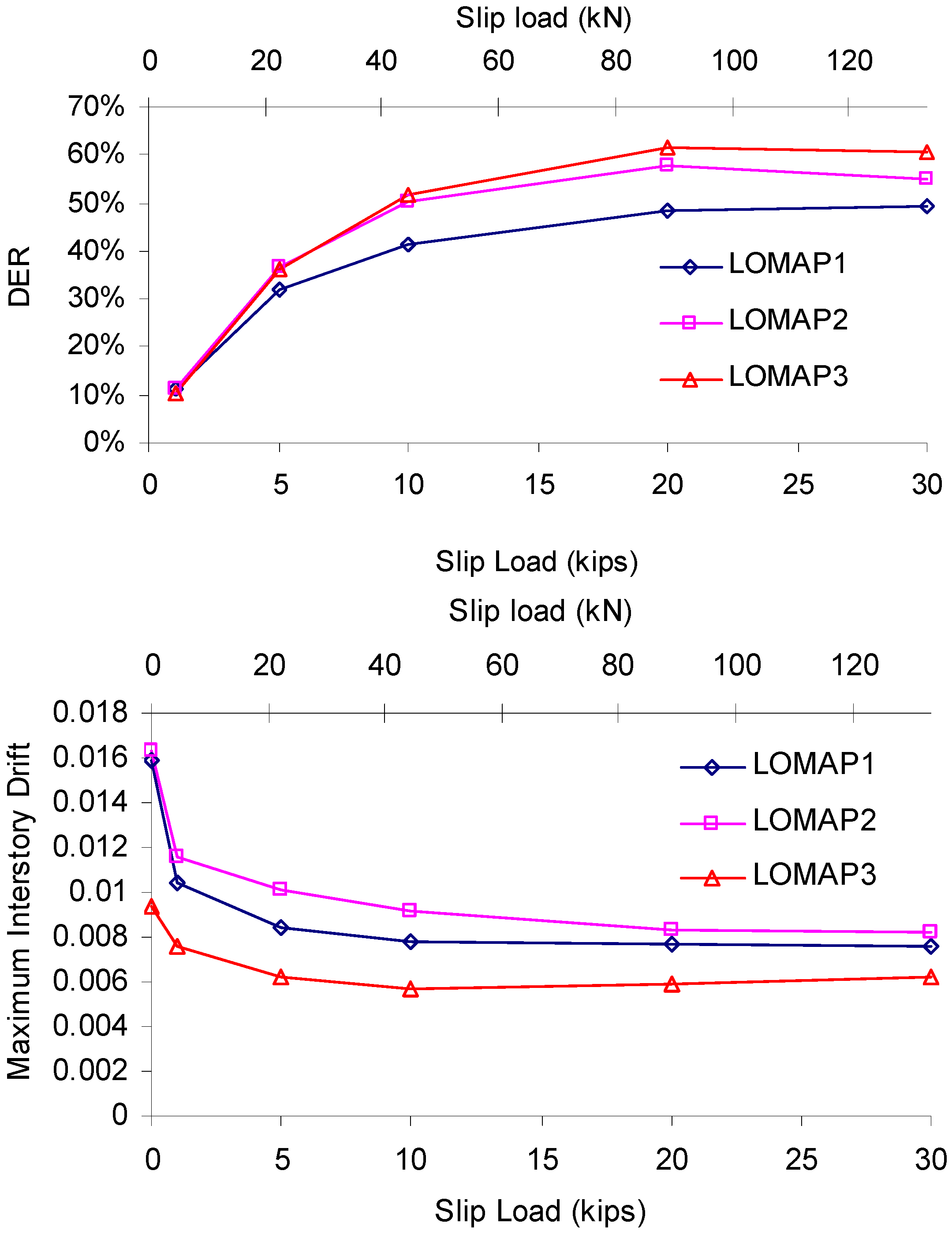
Based on the results of the nonlinear time-history analyses performed on the nine-story one-quarter scale test structure and the 20-story full-scale moment frame building, one can conclude that the new EDCS is able to significantly reduce interstory drift and member forces through the combined action of added stiffness and energy dissipation. This was achieved through careful selection of the slip load level and distribution. Therefore, the selection of slip load is a key design parameter for EDCS.
(2)
The loading condition and stresses developed in the framing members of building with EDCS are expected to be different from conventional moment frame members as a result of the interaction with the EDCS. In particular, columns on which the EDCS is attached are subjected to concentrated load (i.e., slip load) along its height (at about one-third height). The study revealed that this should not pose an issue because the maximum slip load is typically controlled by the capacities of the supporting framing elements.
(3)
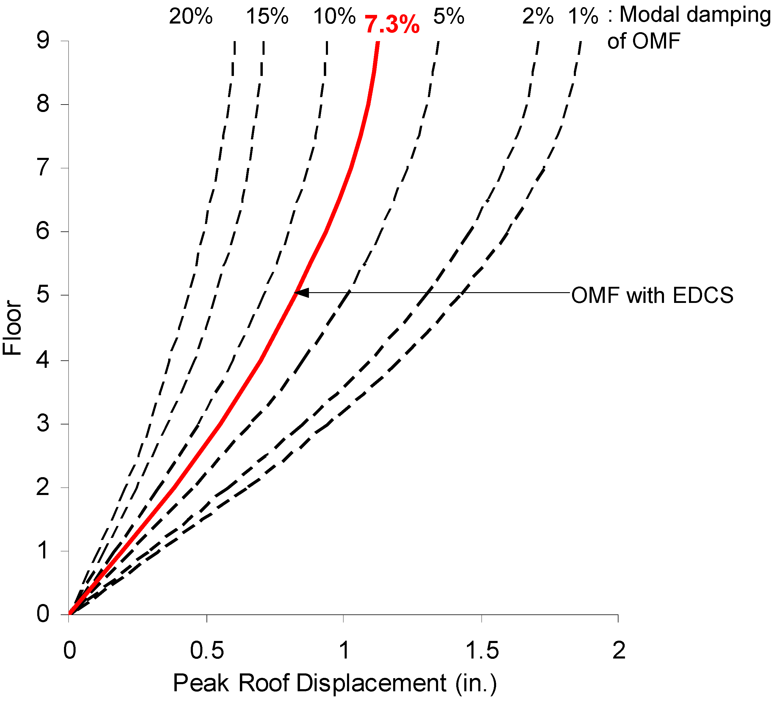
The study on the 20-story building demonstrated that by incorporating the EDCS into a moment resisting frame, it is possible to achieve a reduction in building response comparable to that of a code-specified ordinary moment frame (i.e., response modification factor of 3.5). However, the EDCS design in the example shown does not demand any form of ductility or redundancy from the structural frame itself.
(4)
The design approach adopted for the building incorporating the EDCS is conservative in the sense that the moment frame remains essentially elastic throughout the design earthquake event. This means that the moment frame with EDCS could survive a higher than expected earthquake. Furthermore, the EDCS could be retrofitted into existing ordinary moment frame that was not originally designed for higher levels of ground motions.
(5)
A less conservative approach could be used whereby both the framing members and the EDCS are specifically designed to contribute to the inelastic demand leading to significantly higher reduction in building response because of reduced force demand as a result of inelasticity and ductility. Although this approach could lead to considerable reduction in the size of the structural members and cost saving, it has its challenges. It would be necessary to model accurately both the inelastic behavior of both framing elements and EDCS. However, the inelastic behavior (e.g., location and numbers of plastic hinges) of the ductile moment frame may change as a result of attaching the EDCS. Furthermore, it may not be easy to separate the contribution of each system in reducing the building response. More importantly, the failure of any one of the systems may lead to possible collapse. It is therefore concluded that for a more conservative design, the moment frame should be designed to remain elastic with all inelastic demand provided by the EDCS (i.e., as a DCS).

Author Contributions

The first author Hathairat Maneetes was the graduate student working on the research project that led to her Ph.D. thesis. The second author Ali Memari was the project PI and thesis advisor. Both authors worked on the manuscript through the final submitted form.

Conflicts of Interest

The authors declare no conflict of interest.

References

  1. Wada, A.; Connor, J.J.; Kawai, H.; Iwata, M.; Watanabe, A. Damage tolerant structures. In Proceedings of 5th US-Japan Workshop on the Improvement of Building Structural Design and Construction Practices, San Diego, CA, USA, 1992; pp. 1–12.
  2. Structural Engineers Association of California Seismology Committee. Recommended Lateral Force Requirements and Commentary, 7th ed.; Structural Engineers Association of California: Sacramento, CA, USA, 1999. [Google Scholar]
  3. Maneetes, H. Development of a Seismic Dissipating Mechanism for Precast Concrete Cladding Panels. Ph.D. Thesis, The Pennsylvania State University, University Park, PA, USA, May 2007. [Google Scholar]
  4. Arnold, C. Seismic Safety of the Building Envelope. 2009. Whole Building Design Guide, National Institute of Building Sciences. Available online: http://www.wbdg.org/resources/env_seismicsafety.php (accessed on 21 June 2014).
  5. Maneetes, H.; Memari, A.M. Finite element modelling and analysis of reinforced concrete cladding panels. Electron. J. Struct. Eng. 2009, 9, 62–72. [Google Scholar]
  6. Liu, Y.; Hutchinson, T.C. Nonlinear Modeling for Precast Concrete Cladding Subsystems for High Seismicity Regions. 2011. REU Site University of California at San Diego. Available online: http://nees.org/site/media/pdf/reu2011finalpapers/liu_nees_reu_finalpaper.pdf (accessed on 21 June 2014).
  7. Aiken, I.D.; Kelly, J.M. Earthquake Simulator Testing and Analytical Studies of Two Energy-Absorbing Systems for Multistory Structures; No. UCB/EERC-90/03; Earthquake Engineering Research Center, College of Engineering, University of California: Berkeley, CA, USA, 1990. [Google Scholar]
  8. Computers and Structures Inc. ETABS Analysis Reference Manual Version 8; Computers and Structures Inc.: Berkeley, CA, USA, 2002. [Google Scholar]
  9. Wen, Y.-K. Method for random vibration of hysteretic systems. J. Eng. Mech. Div. 1976, 102, 249–263. [Google Scholar]
  10. American Society of Civil Engineers. Minimum Design Loads for Buildings and Other Structures, ASCE 7-05; American Society of Civil Engineers: New York, NY, USA, 2005. [Google Scholar]
  11. Goodno, B.J.; Craig, J.I. Ductile Cladding Connection Systems for Seismic Design; No. NIST GCR 98-758; National Institute of Standards and Technology: Gaithersburg, MD, USA, 1998. [Google Scholar]
  12. International Code Council, Inc. International Building Code; International Code Council, Inc.: Washington, DC, USA, 2006. [Google Scholar]
  13. American Institute of Steel Construction. AISC Load and Resistance Factor Design Specification for Structural Steel Buildings; American Institute of Steel Construction: Chicago, IL, USA, 2002. [Google Scholar]
  14. Pall, A.S.; Vezina, S.; Proulx, P.; Pall, R. Friction-dampers for seismic control of Canadian space agency headquarters. Earthq. Spectra 1993, 9, 547–557. [Google Scholar]
  15. Filiatrault, A.; Cherry, S. Performance evaluation of friction damped braced frame under simulated earthquake loads. Earthq. Spectra 1987, 3, 57–78. [Google Scholar]

