Wind Load Test of Earthbag Wall

1
Glenn Department of Civil Engineering, Clemson University, 310A Lowry Hall Box 340911, Clemson, SC 29634, USA
2
RMS Risk Management Solutions, Newark, CA 94560, USA
3
Barrels of Hope, Gainesville, FL 32601, USA
*
Author to whom correspondence should be addressed.
Buildings 2013, 3(3), 532-544; https://doi.org/10.3390/buildings3030532
Submission received: 7 June 2013
/
Revised: 3 July 2013
/
Accepted: 22 July 2013
/
Published: 7 August 2013
Abstract
:Earthbag construction is a sustainable, low-cost, housing option for developing countries. Earthbag structures are built of individual soil-filled fabric bags (i.e., sand bags) stacked in a running bond pattern. Once stacked, earthbags are compacted and the soil inside the bags is dried in-place to form earthen bricks. Barbed wires are placed between each course to affect shear transfer within the wall. Results of an out-of-plane load test on a full-scale earthbag wall are presented in this paper. The wall was subjected to out-of-plane pressure up to 3.16 kPa, which resulted in plastic deformations up to 50 mm. The wall did not collapse during loading. Wall behavior and force transfer mechanisms are discussed.
1. Introduction
Adequate housing has been defined as being secure, habitable, affordable, safe, and culturally appropriate. Although such housing has been recognized by international law as a basic human right, well over a billion people are not adequately housed [1]. Research presented in this paper was motivated by a desire to advance technological resources to address the problem of adequate housing.
Earthbag structures offer a sustainable, affordable housing option for developing countries. These structures are comprised of individual fabric bags (i.e., sand bags) filled with soil and stacked in a running bond pattern. Ideally soil is a blend of sandy and cohesive soils such that filled bags can be compacted and dried in-place to form earthen bricks. The bags provide confinement for the soil during compaction and drying. Barbed wires are placed between each course to affect shear transfer between bags. This construction method was pioneered by Gernot Minke of Kassel University in the 1970s [2], and has received increased attention in recent years [2,3,4,5,6,7,8,9].
Earthbag structures have the potential to satisfy multiple criteria required for adequate housing. Soil, the primary material used in these structures, is readily available at little to no cost. Furthermore, earthbag structures can take forms such as domes, curved walls, straight walls, or arches, thereby allowing local adaption to fit cultural housing norms [9].
Research in this paper seeks to address another of the adequate housing criterion, namely safety. Earthbag structures have not typically been engineered, but rather are designed using rules-of-thumb developed through trial and error. Laboratory testing is desirable to directly evaluate the safety and behavior of earthbag wall structures subjected to extreme loads.
Previous research on the capacity of earthbag structures has primarily focused on compressive strength of soil-filled earthbag units [10,11,12,13]. Multiple authors have concluded that fill material significantly impacts the compressive capacity and that compressive failure of earthbag units is often governed by splitting tensile strength of the bag material.
Vadgama [13] and Croft [14] experimentally investigated load transfer mechanisms in earthbag walls. Vadgama reported that shear transfer between courses of earthbags is accomplished through dowel action of barbs on the barbed wire. Croft reported that walls with barbed wire between courses and/or plaster rendering on the wall faces have significantly increased capacity relative to walls without barbed wire and plaster. It was reported that barbed wire alone increased the out-of-plane capacity by 1.6 times, and that plaster alone increased out-of-plane capacity by a factor of 7. In-plane shear capacity also increased due to barbed wire and plaster rendering, although the degree of improvement could not be quantified due to limitations in test set-up. Croft noted that the improvement in in-plane capacity was at least as significant as the improvement on out-of-plane capacity.
Pelly [15] conducted experimental and analytical investigations of earthbag arches subjected to applied loads. The experiments demonstrated that plaster rendering increased strength and stiffness of earthbag arches relative to those without rendering. The author reported the following key conclusion: Earthbag structures are resilient structures that undergo large deformations before collapse, and exhibit highly plastic behavior. In general, stabilized earthbags exhibit block-like behavior at low stresses, and soil-like behavior at stresses approaching peak stress. The research program presented in the current paper was designed to identify whether earthbag wall structures subjected to out-of-plane loading display similar behavior.
2. Test Program
A full-scale earthbag wall was built and tested at the Powell Family Structures Laboratory at the University of Florida. Testing was conducted to evaluate earthbag wall behavior under simulated hurricane wind loads. Loads were applied using the High Airflow Pressure Loading Actuator (HAPLA) system. Details of this system are discussed by Lopez et al. [16]. The following sections present details of wall construction, material properties, and test procedures. Limitations of the test set-up and procedures are also discussed.
2.1. Construction and Materials
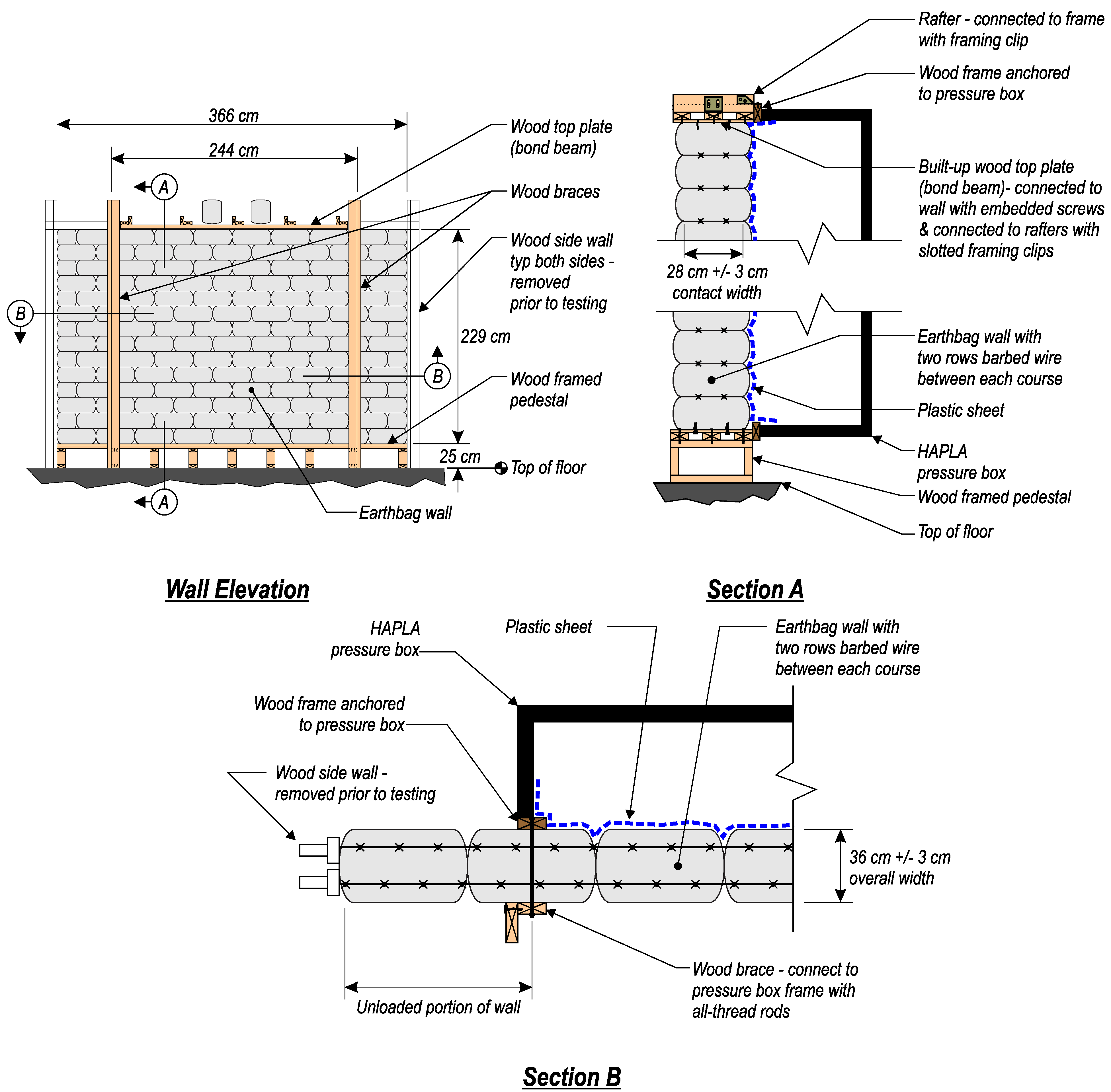
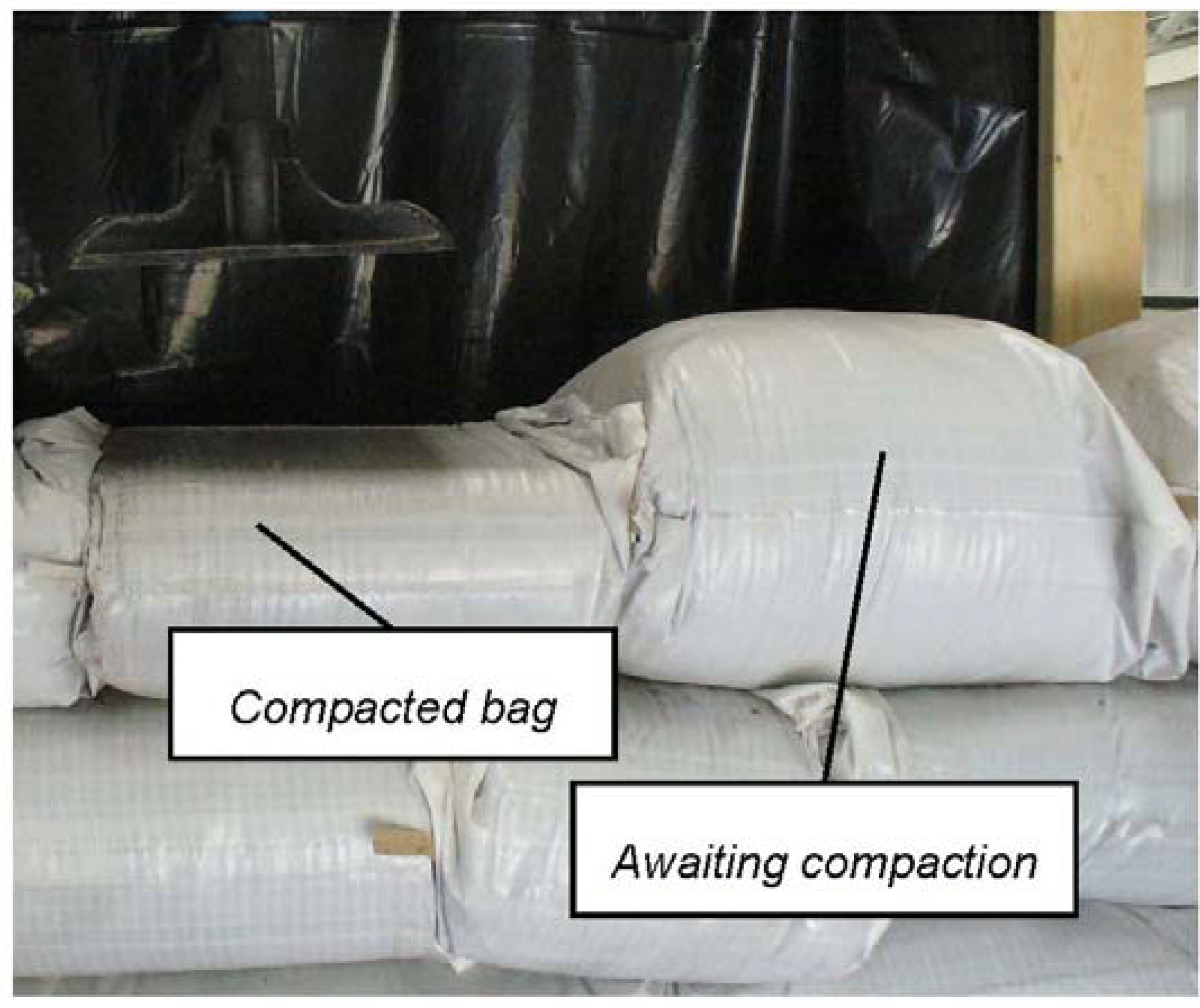
The test wall was approximately 229 cm tall by 366 cm long by 36 cm thick, and was built using 134 individual earthbags (Figure 1). Each bag contained approximately 0.45 kN of soil. Bags were stacked in a running bond pattern. After each course was placed, soil in the bags was compacted by multiple blows with a tamper (Figure 2). Outer dimensions of compacted bags were approximately 17 cm tall by 41 cm long by 36 cm wide. Half-sized bags were used at the ends on every second course to form the running bond pattern. A wood side wall was framed at each end of the earthbag wall to restrain in-plane movement of the bags during compaction. The wood side wall was removed from the wall ends prior to testing.
Figure 1.
Elevation and details of earthbag test wall.

Figure 2.
Earthbag compaction during wall construction.

Soil used in the earthbags was fill material with some surficial roots and small rocks and was donated by a local building contractor. It was non-uniform slightly silty sand with a dark gray coloring. The water content in the soil was also non-uniform. Based on observation during wall construction, soil used for most of the wall had a lower than optimal moisture content for compaction. Approximately 40 bags in the top-half of the wall were filled with soil that had been stored outside and exposed to the rain. Water flowed out of the pores in these bags as they were compacted, suggesting that the soil was close to the saturation limit. The wall was tested three days after bags were stacked and compacted, and the wet soil was not able to dry before load testing.
The bags were made of 900 dtex polypropylene. Empty bags were approximately 46 cm by 76 cm. The bags were tubular in construction with the bottom sewn closed. During stacking, the top of the bags were folded under to prevent loss of soil during compaction and load testing. Two rows of galvanized barbed wire were placed between each course of bags. Each row of barbed wire consisted of two individual wires twisted together with four 1.3 cm long barbs spaced at 13 cm. Individual wires were 1.94 mm in diameter. The cross-sectional area of barbed wires between each course was 5.91 mm2.
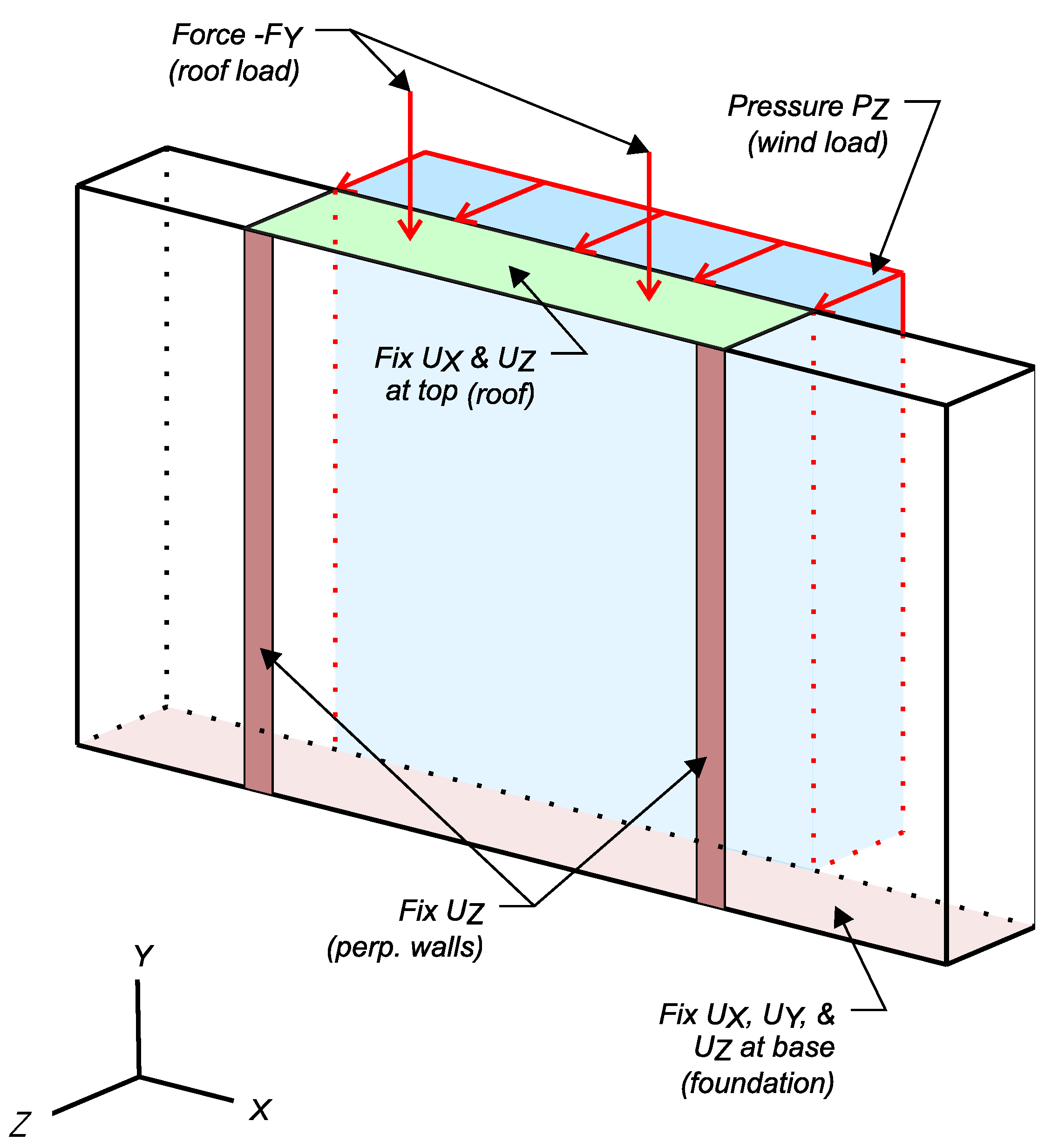
Wall details were designed to create the boundary and load conditions shown in Figure 3. Translation at the base of the wall was restrained in the Z-direction by connection with the wood pedestal. The connection was accomplished by embedding screws protruding from the pedestal into the lowest course of bags. The screws were embedded 5 cm, and were spaced at 13 cm on center in two rows 13 cm apart.
Vertical wood braces were placed 244 cm apart on the front of the wall. Braces were placed flat and provided restraint against Z-direction (out-of-plane) translation, similar to restraint that would be provided by perpendicular walls in an earthbag dwelling. The braces were aligned with the edges of the HAPLA pressure box and were connected to the frame around the pressure box with threaded rods spaced at 61 cm.
A wood plate consisting of dimensional lumber and oriented strand board was used to simulate a bond beam at the top of the wall. The plate was connected to the top course using protruding screws similar to the connection at the base of the wall. The top of the wall was detailed to allow free movement in the Y-direction (vertical), but restrain movement in the X and Z directions. This was accomplished by using slotted framing clips to attach the bond beam to the simulated rafters. The simulated rafters were attached to the pressure box using unslotted framing clips.
A plastic sheet was placed behind the wall to prevent air from leaking through gaps in the wall during testing. The sheet was attached to the inside of the pressure box using adhesive tape, and was placed with enough slack that it did not dislodge from the box as the wall deflected during the tests.
The wall was constructed, tested, and disassembled within a two week period in March 2011. Labor for construction was provided by student volunteers from the University of Florida Chapter of Engineers Without Borders. Most of the volunteers had no prior experience building with earthbags. Construction oversight was provided by volunteers from Barrels of Hope, a Florida based organization that assists in earthbag construction projects in Haiti.
Figure 3.
Test wall boundary and loading conditions.
2.2. Test Procedures
The test wall was loaded in the Y (vertical) and Z (out-of-plane) directions. Gravity loading consisted of the wall self-weight and two 0.38 kN earthbags placed on top of the wall to simulate roof loads. Out-of-plane loading consisted of a pressure load generated by the HAPLA system.
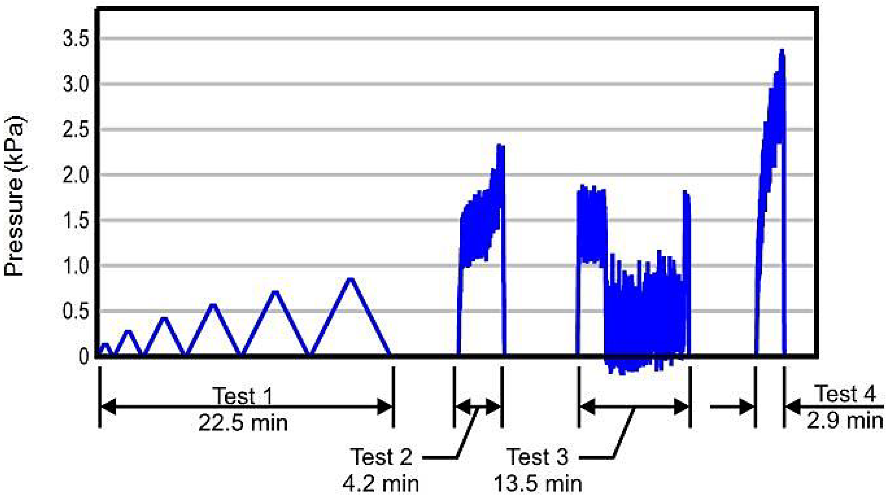
Four different stages of pressure loading were applied (Figure 4) within a two hour period. A series of ramped loads with increasing magnitude were applied during stage 1 to verify the safety of the wall at lower loads and to decide upon target pressures for the subsequent stages. Stages 2 and 4 were proof-load tests designed to evaluate wall behavior under static loading. Stage 3 included a dynamic pressure time-history to evaluate wall behavior under simulated hurricane conditions. Pressures in stages 2–4 are of the magnitude expected during hurricane events.
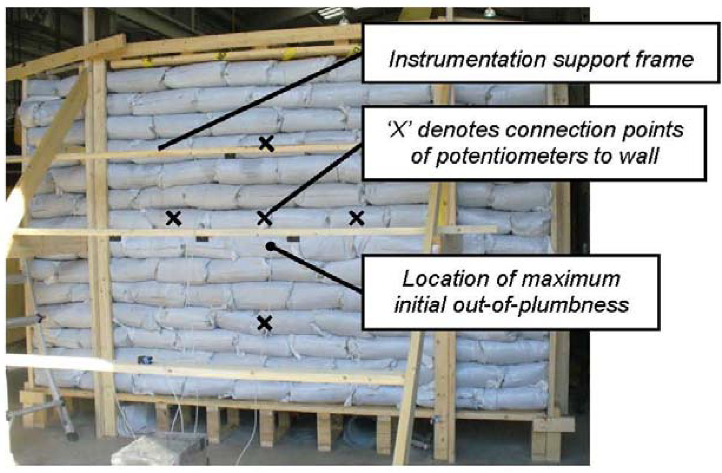
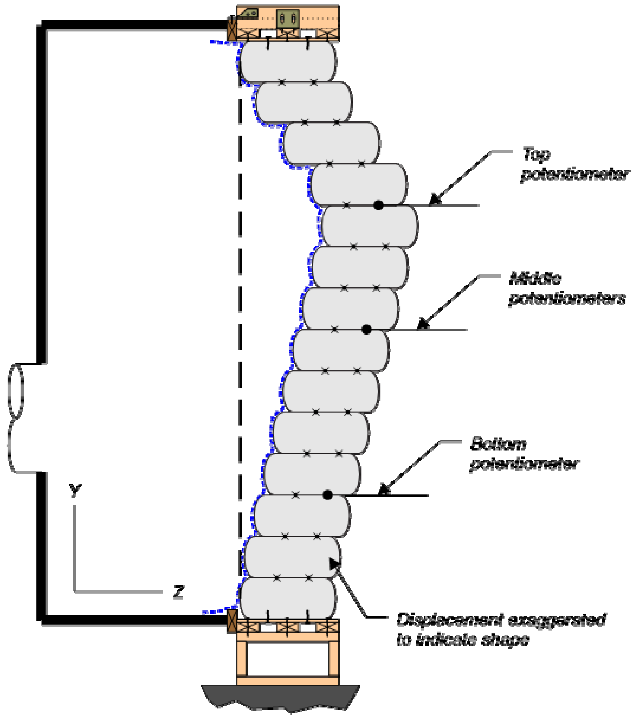
A transducer inside the pressure box monitored pressure during testing. Z-direction wall displacement was monitored using five string potentiometers mounted to a wood frame located in front of the wall (Figure 5). Z-direction movement of the top plate was monitored using a laser displacement sensor. Data from all of the instruments was continuously logged at 100 Hz. The position of the wall was also documented by tape measure and photographs before and after testing.
Figure 4.
Pressure time history.

Figure 5.
Completed test wall and instrumentation.

2.3. Limitations
The test wall had some critical differences with walls constructed using the best practice techniques reported in the available earthbag building guides [5,6,7]. These differences were undesirable, but were necessary to satisfy time and resource constraints of the project. Most of the differences weakened the test wall relative to a wall built using best practices. Accordingly, test results were considered to be a lower bound of earthbag wall capacity and behavior.
Sandy-clay soil at optimal water content is the recommended earthbag fill material. After placement and compaction this material dries to form earthen bricks. It is also recommended that sandy-clay material be placed to fill the cracks between bags and that a plaster render be applied as a finish to wall surfaces.
The test wall utilized a silty-sand soil that did not have desirable cohesive properties. Water content was undesirable during compaction, being either too dry or too wet depending on location in the wall. The compacted bags were not allowed to harden and dry before testing. Furthermore, cracks between the bags were not filled and no plaster finish was applied to the wall surfaces. These differences are believed to have reduced the strength and stiffness of the test wall relative to a wall built using the recommended practices.
The test wall was unintentionally built out-of-plumb. The maximum out-of-plumb eccentricity was approximately 40 mm and occurred near the center of the wall at mid-height (Figure 5). The top, bottom and sides of the wall were within the same plane, and the eccentricity was limited to the middle of the wall. The direction of the eccentricity corresponded with the direction of wall displacements during loading, and resulted in a self-weight moment in the wall that acted in conjunction with the pressure loads.
The vertical boundary conditions for the test wall were designed to mimic supports provided by perpendicular walls spaced approximately 244 cm part. Results of the test program are thus specific to walls with similar bracing. Earthbag walls with other wall boundary conditions, such as at corners or with braces spaced greater than 244 cm, may not be comparable with the test results.
Displacement measurements taken by string potentiometers during the load tests were compromised by unintentional shifting of the wood frame that held the instruments (Figure 5). The shifting events appear as sudden drops in the displacement data (Figure 6) and made it impossible to determine absolute displacements from the potentiometer data. Relative displacement data from the potentiometers were still useful and are discussed in the next section. Frame shifting did not affect the measurements of the wall position taken by tape measure before and after testing.
Figure 6.
Test 2 displacement and pressure data. Sudden jumps in displacement occurred due to settlement of the instrumentation support frame.
Figure 6.
Test 2 displacement and pressure data. Sudden jumps in displacement occurred due to settlement of the instrumentation support frame.

3. Results and Discussion
Figure 6 shows the pressure and displacement history from test 2. Data from test 2 are representative of the behaviors and trends observed in the other tests. As previously noted, the frame holding the string potentiometers shifted multiple times during testing. The shift events are labeled in the Figure 6.
The largest relative displacements were reported by the top potentiometer and the smallest were reported by the bottom potentiometer (Figure 5 and Figure 6). This result was confirmed by visual observation (Figure 7) of wall deformation and is attributed to variation in friction forces throughout the wall. Friction forces were greatest at the bottom of the wall because self-weight axial force, and consequently friction force was proportional to the vertical distance from the top of the wall. Larger friction forces lower in the wall provided additional restraint and resulted in relative displacements that were smaller than those reported at the top of the wall. It is concluded that out-of-plane forces were in-part transferred vertically in the test wall though friction between bags.
Figure 7.
Exaggerated displacement of wall based on visual observations. The largest displacements occurred near the top potentiometer.
Figure 7.
Exaggerated displacement of wall based on visual observations. The largest displacements occurred near the top potentiometer.

Relative displacements from the left and right potentiometers were similar indicating symmetrical deformations about the centerline. This result was expected because the load and boundary conditions were also symmetrical about the wall centerline.
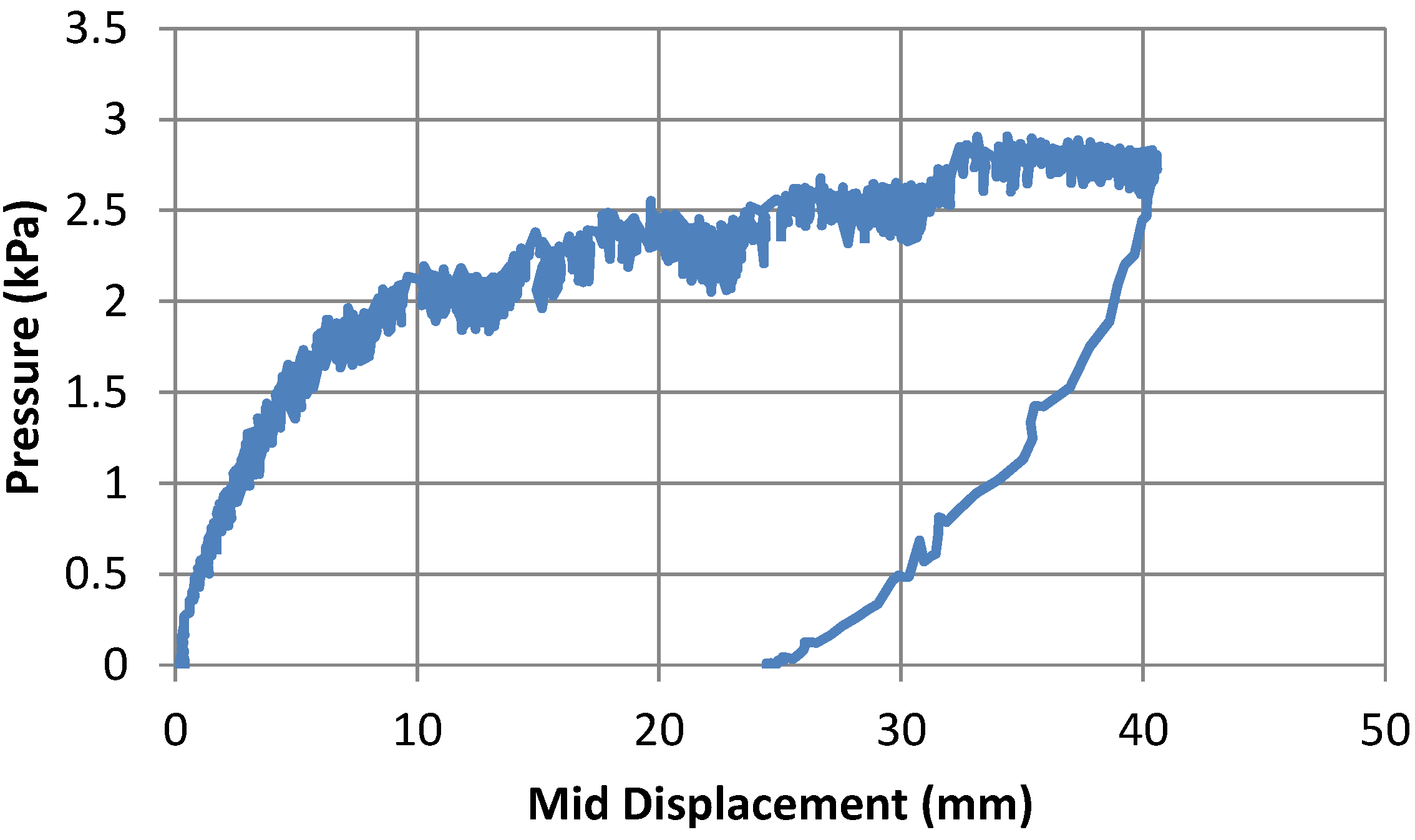
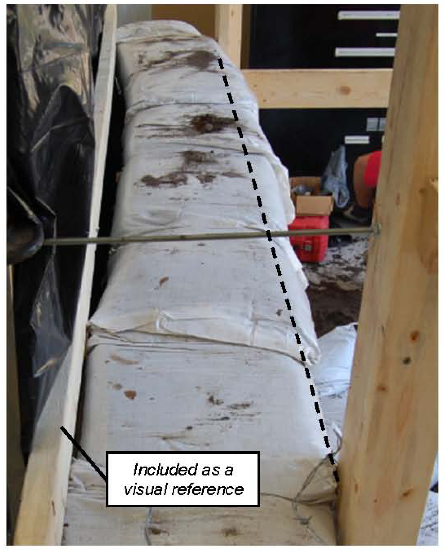
Displacement of the top plate relative to the pressure box was monitored using a laser deflection device which reported a maximum displacement of 4 mm occurring at peak load during test 4. Displacements at the side and bottom supports were not monitored, however similar to the top plate they were also attached to the pressure box. Accordingly, displacements at these supports are assumed to have been inconsequential on test results. Furthermore, inspection of the supports after the completion of testing did not indicate any significant permanent displacement of the supports. Displacement reported by the middle potentiometer during test 4 is shown in Figure 8. The figure shows the displacement relative to the beginning of test 4 and does not include plastic deformation from the previous tests. The frame supporting the potentiometers did not shift significantly during test 4. The pressure-displacement response was effectively linear until a pressure of approximately 1.6 kPa when the wall began to displace plastically. A similar result was observed in test 2, where plastic deformation was reported beginning at approximately 1.4 kPa. In both cases, displacement at the onset of plastic behavior was approximately 5mm. This displacement is equal to the wall height divided by 45. Wall height divided by 180 is often used as a threshold for acceptable wall displacements. For the test wall, a displacement of 1.3 mm and a pressure of 0.5 kPa correspond to this threshold. Greater stiffness would be expected in walls finished with plaster rendering. The majority of deformations due to loading were plastic. Figure 9 shows the wall during deconstruction. At the time of the picture the top half of the wall had been removed. Permanent deformation due to loading was approximately 50 mm at the centerline of the wall at mid-height. Combined with the unintentional eccentricity built into the wall, the final position of the wall at the location shown was approximately 90 mm out-of-plane.
Although the majority of wall displacements were plastic, the wall also exhibited partial elasticity when load was removed at the end of each test stage. This behavior can be observed in Figure 6 and Figure 8, where displacement rebounded partially as load was removed. This behavior is attributed to elastic response of the barbed wire and possibly due to partial elastic response of the soil. Of these factors the barbed wire is thought to be more significant. During deconstruction it was observed that out-of-plane deformations were sufficient to pull the barbed wires taut, confirming that the barbed wires were engaged in tension during load testing and could have contributed to the observed elastic response.
Figure 8.
Pressure-displacement relationship at middle of wall for test 4.

Figure 9.
Permanent wall displacement as observed during wall deconstruction.

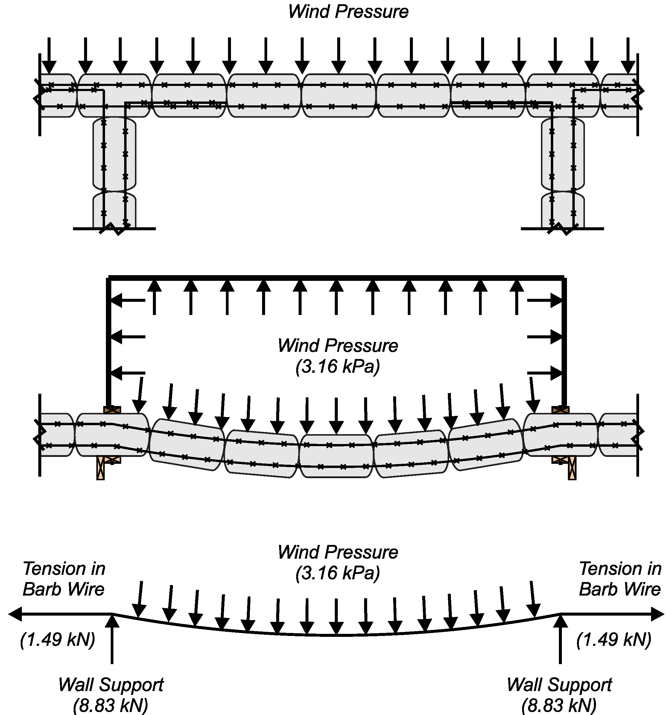
The effect of barbed wire tension is described conceptually in Figure 10. Forces were carried horizontally through the wall by the tension in the wires. Reactions at the end of the wires were supported in the X-direction by pull-out resistance of the wires embedded in the wall extensions beyond the pressure box and in the Z-direction by the wood braces placed in front of the wall.
Figure 10.
Plan view of earthbag structure (top); plan view of test wall (middle); estimated forces in barbed wire and wall supports at peak pressure (bottom).
Figure 10.
Plan view of earthbag structure (top); plan view of test wall (middle); estimated forces in barbed wire and wall supports at peak pressure (bottom).

The tension force in the wires was estimated using an analogy to pressure vessel theory, and by assuming that the wires were deformed into a roughly circular shape with a radius of curvature of approximately 825 cm. Both assumptions are reasonable considering the wall geometry, measured wall deformations, and observed deformed shape (Figure 9). For the pressure vessel analogy the barbed wires carried circumferential tension forces similar to a vessel wall, and internal pressure was equal to the wind pressure applied by the HAPLA system. Force transfer via friction was neglected. Accordingly, the estimated tension in the wires at peak load was 1.491 kN (504 MPa). The in-plane component of the tension force was reacted by the pull-out capacity of the wires in the wall extensions. Based on pull-out test results by Stouter [17] the anchorage provided by the wall beyond the wood braces was sufficient to develop the calculated force.
These calculations highlight the importance of barbed wire and of out-of-plane bracing in earthbag structures. The barbed wire transferred forces through tensile action, which was restrained in the out-of-plane direction by the wood braces. Had the braces been spaced further apart, the barbed wire, and consequently the wall, would have displaced a greater amount to achieve the same load carrying capacity. Greater displacements may have resulted in collapse of the wall prior to engagement of the barbed wire. Accordingly, results of the wall test are not applicable to walls with perpendicular supports spaced farther than 244 cm apart. Until additional information is available, it is recommended that earthbag walls with similar aspect ratios to the test wall be built with perpendicular supports spaced no greater than 244 cm.
In addition to friction between bags and tension in the barbed wire, self-weight and internal moments in the wall may also have contributed to out-of-plane load capacity of the test wall. Self-weight of the wall, ideally acting at the wall centerline, prevents wall instability due to rotation of wall units. Force transfer though this mechanism would be most effective in walls that are stacked plumb and that have dried rigid earthbags. These conditions were not present in the test wall and no conclusions are drawn from the available data.
It is also possible that out-of-plane loads were carried by internal moments in the test wall similar to the moment carrying mechanism in reinforced concrete members. Load transfer by this mechanism would have required a force couple of tension in the barbed wire and compression in the earthbags. As with self-weight, this mechanism would be most effective in walls with dried rigid earthbags where compression in the bags could be developed at low strains. Based on the plasticity of the soil in the test wall, it is believed that very little force was carried through this mechanism.
4. Summary, Conclusions and Recommendations
An earthbag wall was constructed and tested under out-of-plane loading. The wall was approximately 229 cm high, 366 cm long and 36 cm thick. It was reinforced with two rows of barbed wire between each course of earthbags. The test wall was not built using the best practices recommended by earthbag construction guides, and thus represents a lower bound for capacity and behavior. Key observations and conclusions are as follows:
- The wall did not collapse during testing. It supported a maximum out-of-plane pressure of 3.16 kPa and a maximum out-of-plane displacement of 50 mm.
- Wall deformation was primarily plastic and occurred due to shear deformation between courses of earthbags. This result supports Pelly’s [14] conclusion that earthbag structures undergo large deformations and highly plastic behavior before collapse.
- Barbed wires were not initially taut, but were engaged in tension as the wall displaced during load testing. Tension in the barbed wires transferred load horizontally in the test wall to the perpendicular supports. After the barbed wires were engaged they impeded additional displacements and contributed to wall capacity.
Test results demonstrated the strength and ductility of earthbag wall systems, and confirmed the structural viability of this construction system for hurricane prone areas. The following recommendations are made for those constructing earthbag wall structures:
- Out-of-plane wall bracing was critical to the observed strength and ductility of the test wall. For walls with aspect (height-to-thickness) similar to the test wall, out-of-plane supports (e.g., perpendicular walls, corners, pilasters) should be spaced at no more than 250 cm. Larger spacing may be appropriate for walls built using best practices, but these conditions were not validated by the test program.
- Barbed wires were critical components of force transfer at higher loads. To be effective, barbed wire should be place taut in the wall and should be anchored at all out-of-plane supports.
Acknowledgments
This project was only realized through the donation of time, materials, and funds by numerous individuals and organizations. Funding was provided by Kwang Lee and Heather Bigley, and by the University of Florida College of Engineering. The test wall was constructed by student volunteers from the University of Florida Chapter of Engineers Without Borders. The authors thank Forrest Masters for granting access to the test equipment, and Scott Bolton for his technical assistance throughout construction and testing. Scott Wasman assisted with soil classification and description. Finally, the authors dedicate this work to the late Brendan Beck, a civil engineer and fellow Florida Gator, who tragically lost his life in the 2010 Haitian earthquake.
Conflict of Interest
The authors declare no conflict of interest.
References
- Office of the United Nations High Commissioner for Human Rights, The Right to Adequate Housing; United Nations: Geneva, Switzerland, 2009.
- Kelly, H. History. Available online: http://www.earthbagbuilding.com/history.htm (accessed on 23 July 2013).
- Cal-Earth Institute Home Page. Available online: http://calearth.org/ (accessed on 23 July 2013).
- Barrels of Hope for Haiti. Available online: http://barrelsofhope.org/ (accessed on 23 July 2013).
- Wojciechska, P. Building with Earth; Chelsea Green Publishing Company: White River Junction, VT, USA, 2001. [Google Scholar]
- Hunter, K.; Kiffmeyer, D. Earthbag Building; New Society Publishers: Gabriola Island, Canada, 2004. [Google Scholar]
- Geiger, O. Earthbag Building Guide. Available online: http://www.earthbagbuilding.com/resources.htm (accessed on 23 July 2013).
- Barnes, B.; Cao, H.; Drab, T.; Pearson, J. Design of sustainable relief housing in Ethiopia: An implementation of cradle to cradle design in earthbag construction. Am. J. Environ. Sci. 2009, 5, 137–144. [Google Scholar] [CrossRef]
- Daigle, B.; Hall, K.; MacDougall, C. Earthbag housing: Structural behavior and applicability in Sri Lanka. ICE Eng. Sustain. 2011, 164, 261–273. [Google Scholar] [CrossRef]
- Lohani, T.N.; Matsushima, K.; Aqil, U.; Mohri, Y.; Tatsuoka, F. Evaluating the strength and deformation characteristics of a soil bag pile from full-scale laboratory tests. Geosynth. Int. 2006, 13, 246–264. [Google Scholar] [CrossRef]
- Tantono, S.F. The Mechanical Behavior of a Soilbag under Vertical Compression; Graz University of Technology: Graz, Austria, 2008. [Google Scholar]
- Dunbar, R.; Wipplinger, L. Prism Testing of Polypropylene Earthbags. Available online: http://www.earthbagbuilding.com/Testing/prismtest.htm (accessed on 23 July 2013).
- Vadgama, N. A Material and Structural Analysis of Earthbag Housing. Master Thesis, Bath University, Bath, UK, April 2010. [Google Scholar]
- Croft, N. Structural Resistance of Earthbag Housing Subject to Horizontal Loading. Master Thesis, Bath University, Bath, UK, 2011. [Google Scholar]
- Pelly, R. Plastic limit analysis of earthbag structures. Struct. Eng. 2011, 89, 14–16. [Google Scholar]
- Lopez, C.; Masters, F.J.; Bolton, S. Water penetration resistance of residential window and wall systems subjected to steady and unsteady wind loading. Build. Environ. 2011, 46, 1329–1342. [Google Scholar] [CrossRef]
- Stouter, P. Friction and Tensile Strength of Earthbag Components. 2010. Available online: http://www.earthbagbuilding.com/pdf/FrictionandTensile.pdf. (accessed on 23 July 2013).
© 2013 by the authors; licensee MDPI, Basel, Switzerland. This article is an open-access article distributed under the terms and conditions of the Creative Commons Attribution license (http://creativecommons.org/licenses/by/3.0/).
Share and Cite
MDPI and ACS Style
Ross, B.E.; Willis, M.; Datin, P.; Scott, R. Wind Load Test of Earthbag Wall. Buildings 2013, 3, 532-544. https://doi.org/10.3390/buildings3030532
AMA Style
Ross BE, Willis M, Datin P, Scott R. Wind Load Test of Earthbag Wall. Buildings. 2013; 3(3):532-544. https://doi.org/10.3390/buildings3030532
Chicago/Turabian StyleRoss, Brandon E., Michael Willis, Peter Datin, and Ryan Scott. 2013. "Wind Load Test of Earthbag Wall" Buildings 3, no. 3: 532-544. https://doi.org/10.3390/buildings3030532