Gradient Distribution of Microstructures and Mechanical Properties in a FeCoCrNiMo High-Entropy Alloy during Spark Plasma Sintering

 ,
,
Abstract
:1. Introduction
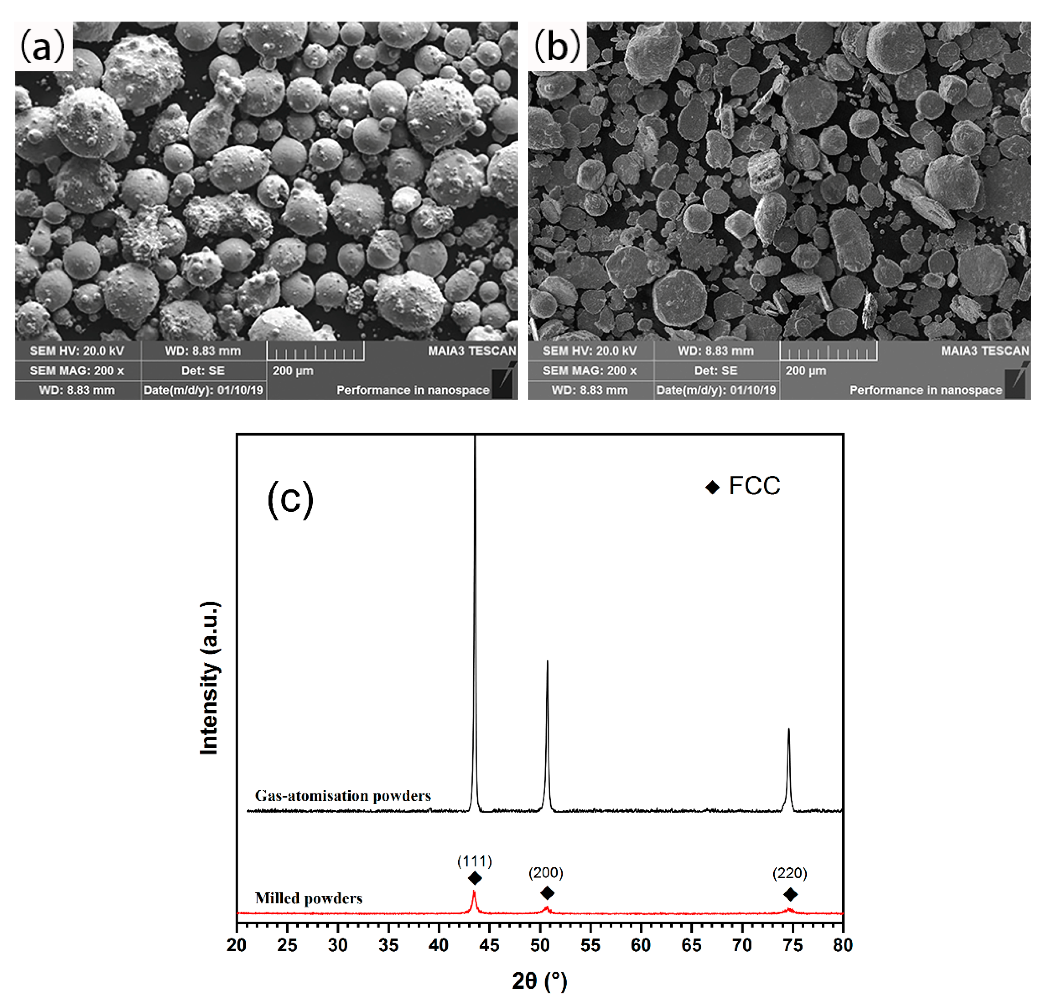
2. Experimental
3. Results and Discussion
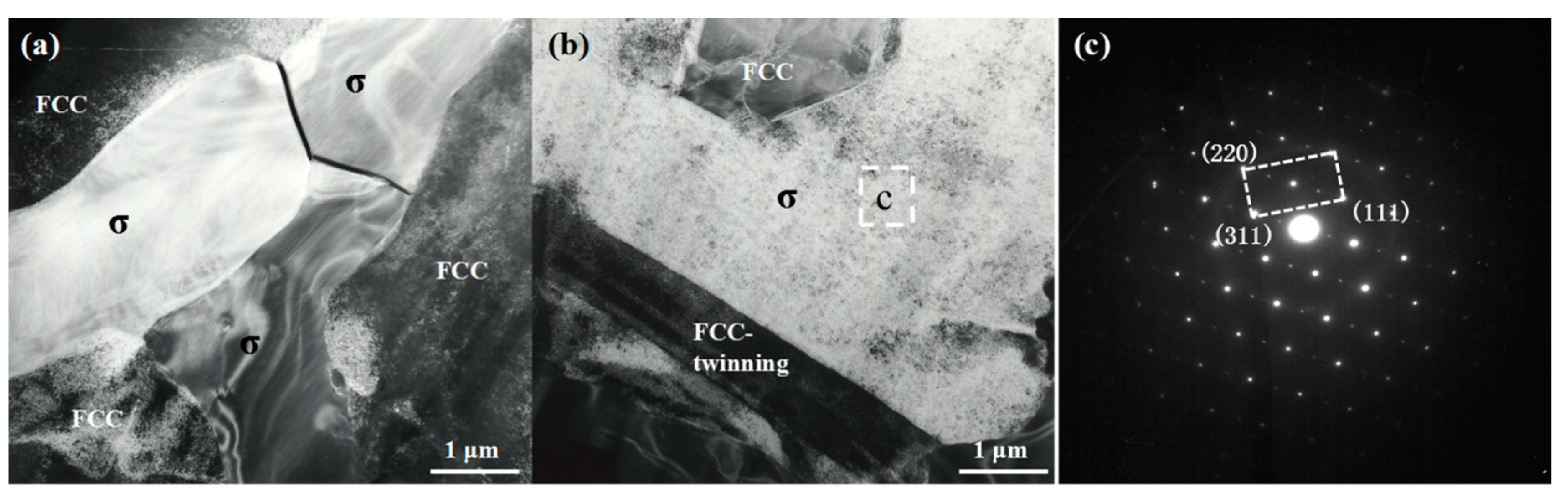
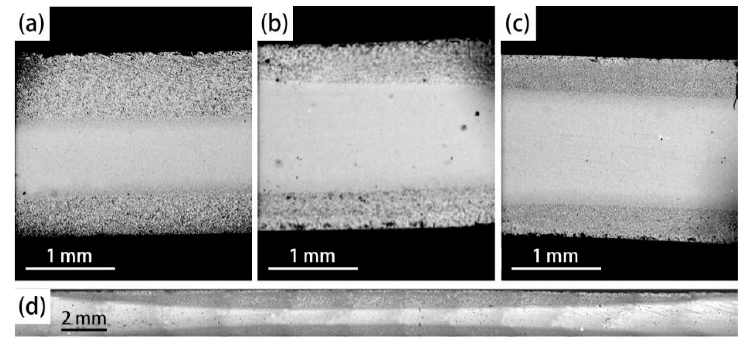
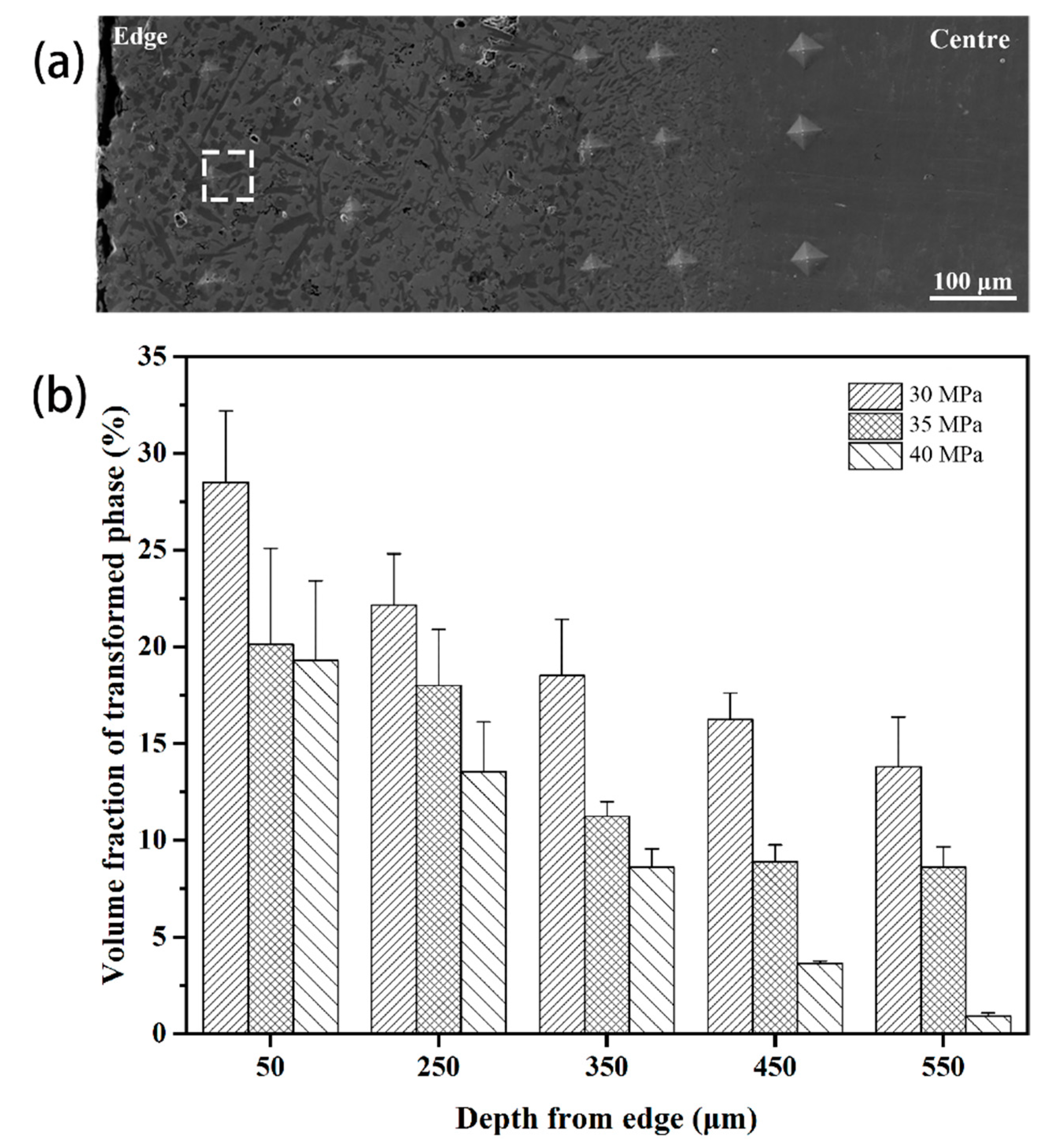
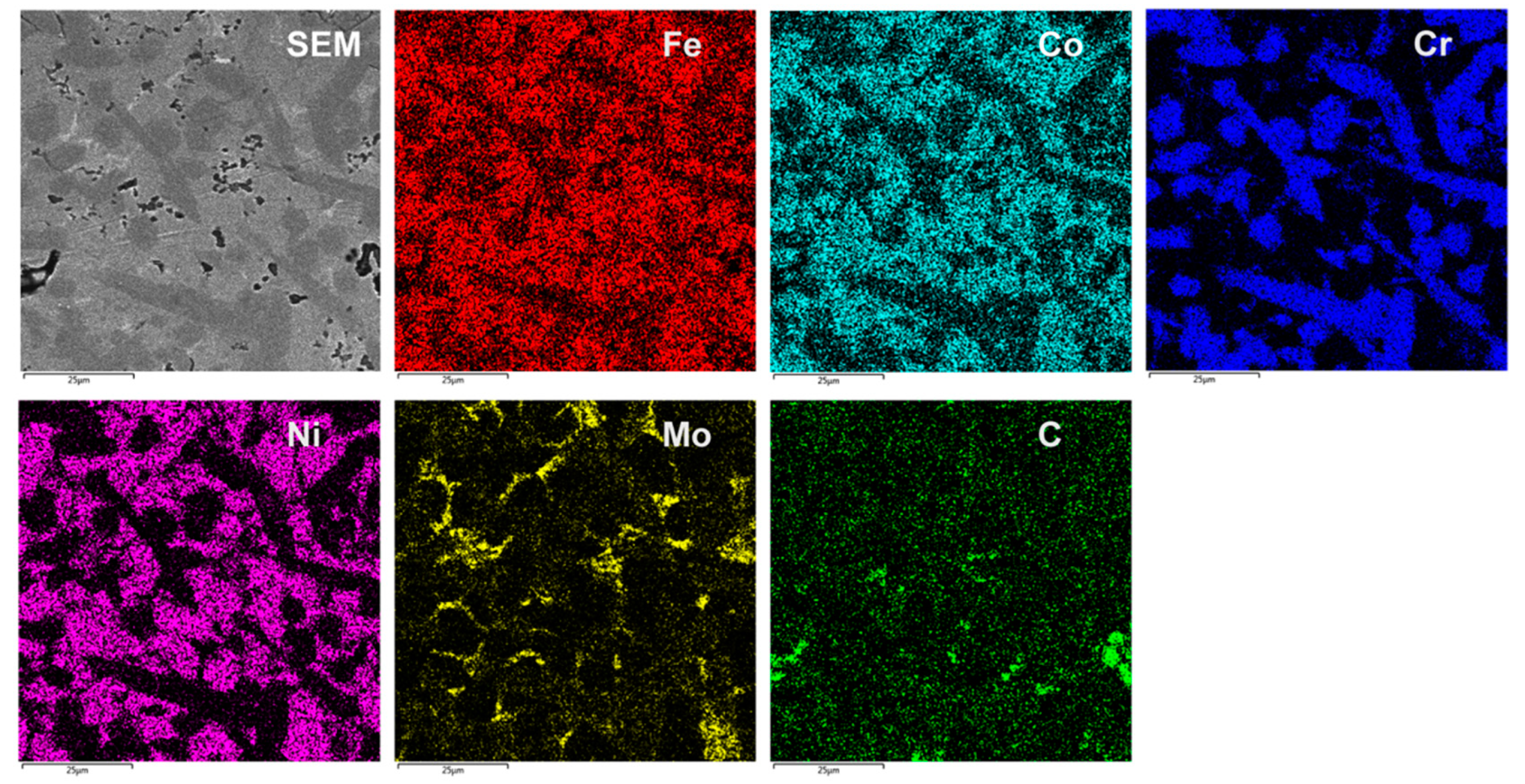
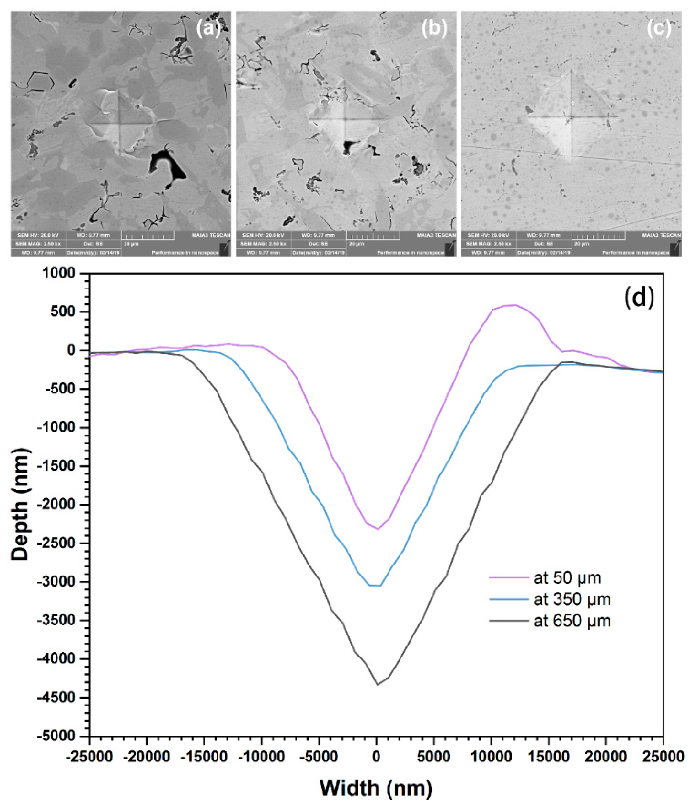
3.1. Microstructure
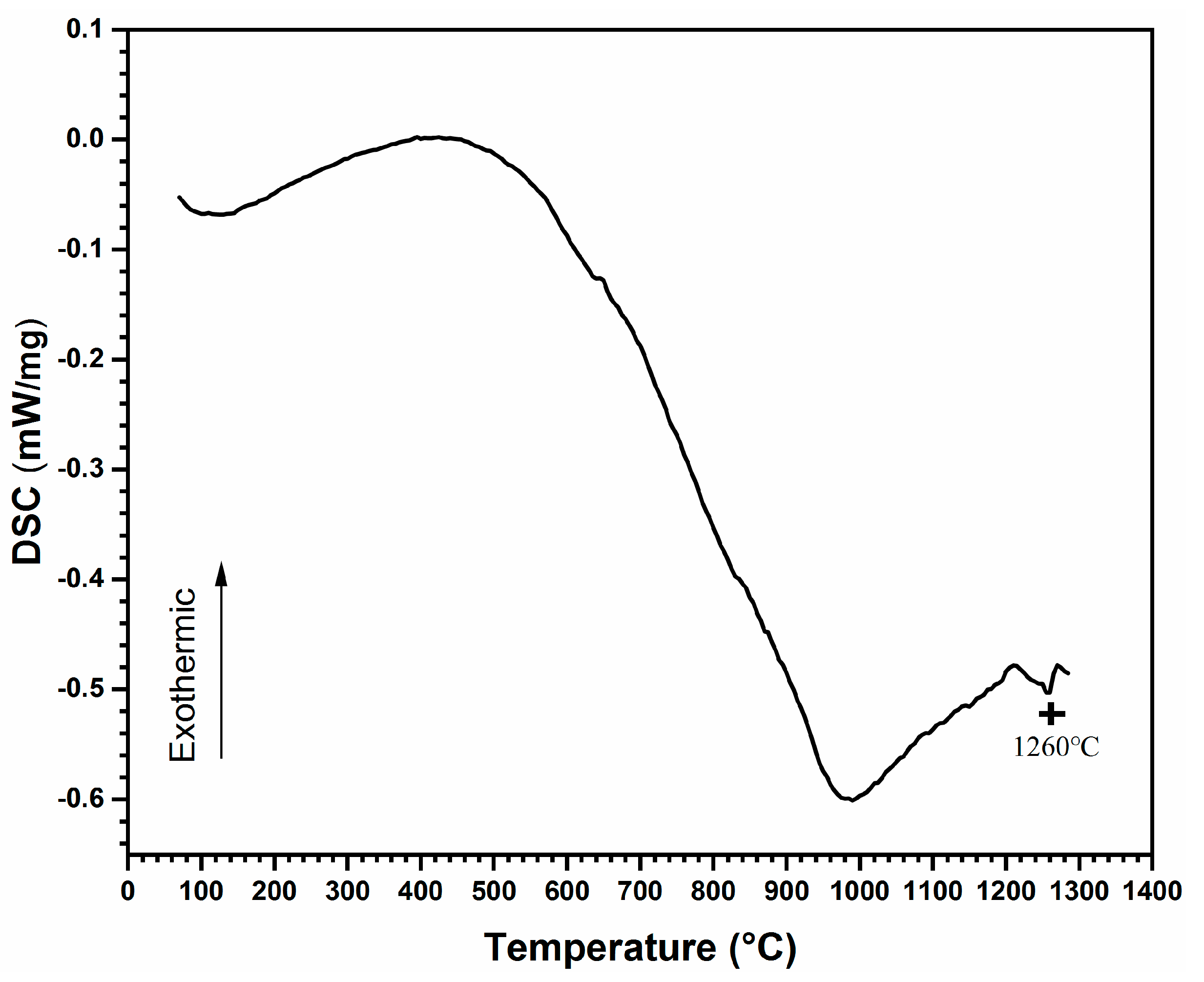
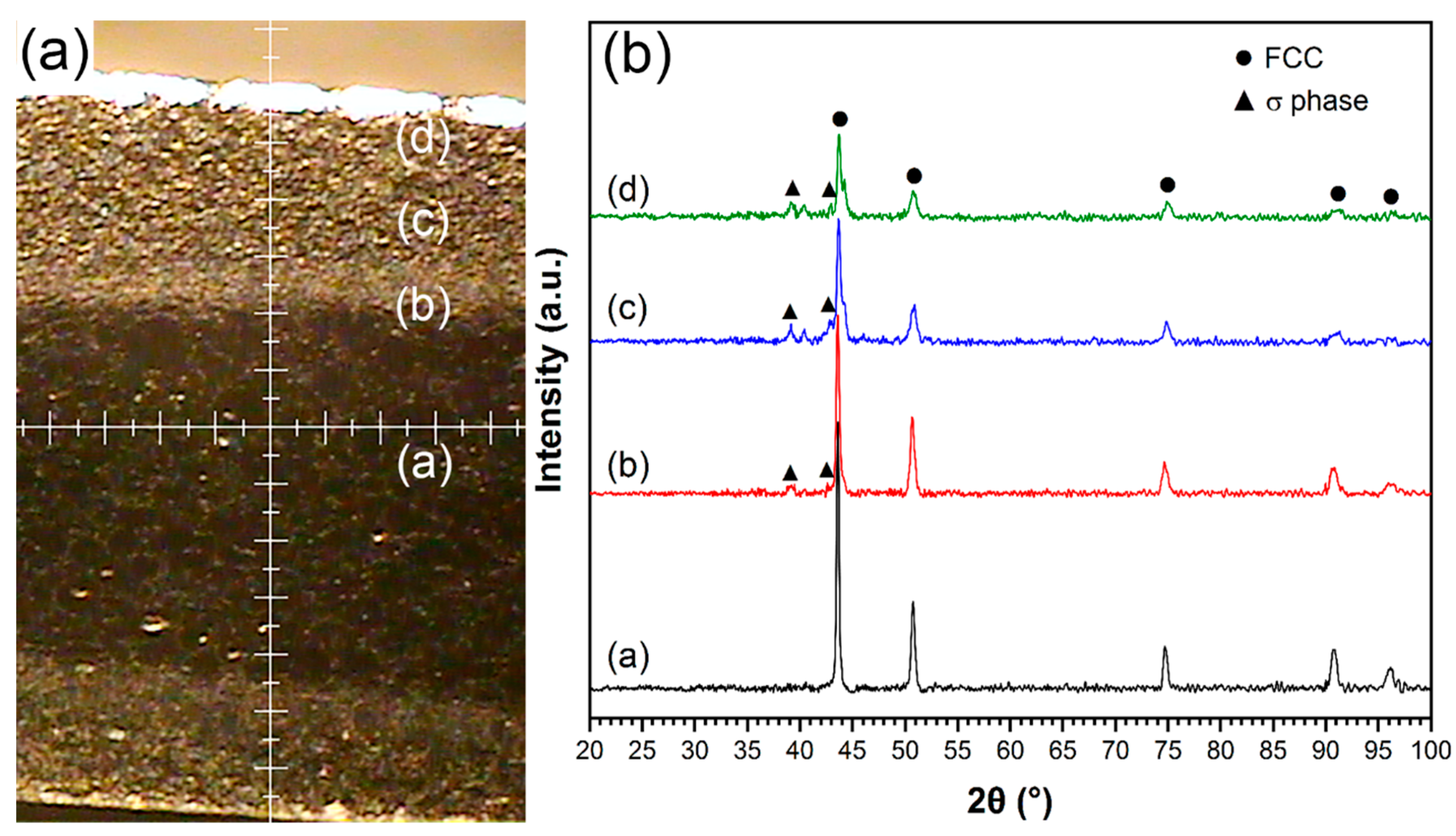
3.2. Phase Identification
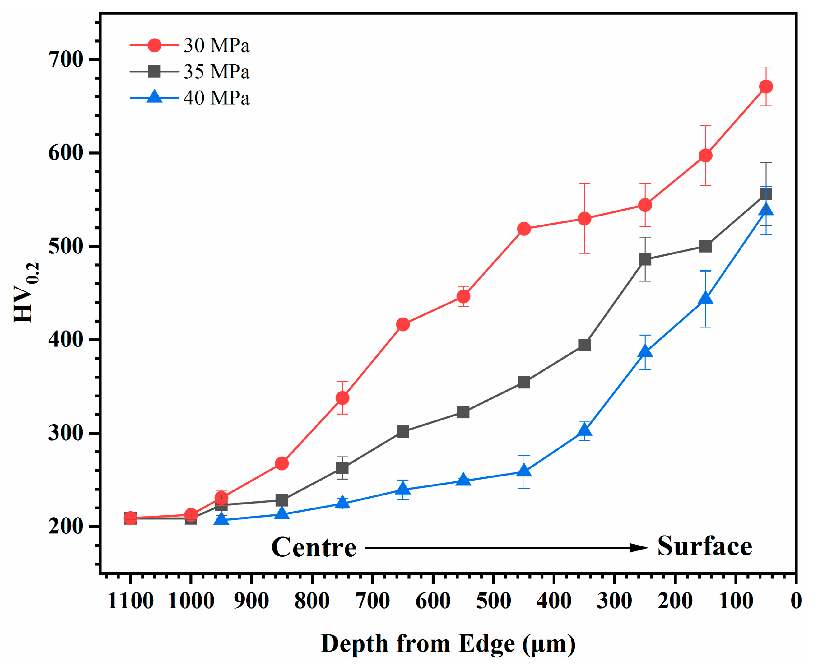
3.3. Mechanical Properties
4. Conclusions
Author Contributions
Funding
Acknowledgments
Conflicts of Interest
References
- Yeh, J.W.; Chen, S.K.; Lin, S.J.; Gao, M.C.; Dahmen, K.A.; Liaw, P.K.; Lu, Z.P. Nanostructured high-entropy alloys with multiple principal elements: Novel alloy design concepts and outcomes. Adv. Eng. Mater. 2004, 6, 299–303. [Google Scholar] [CrossRef]
- Zhang, Y.; Zuo, T.T.; Tang, Z.; Gao, M.C.; Dahmen, K.A.; Liaw, P.K.; Lu, Z.P. Microstructures and properties of high-entropy alloys. Prog. Mater. Sci. 2014, 61, 1–93. [Google Scholar] [CrossRef]
- Tsai, M.H.; Yeh, J.W. High-entropy alloys: a critical review. Mater. Res. Lett. 2014, 2, 107–123. [Google Scholar] [CrossRef]
- Chuang, M.H.; Tsai, M.H.; Wang, W.R.; Lin, S.J.; Yeh, J.W. Microstructure and wear behavior of AlxCo1.5CrFeNi1.5Tiy high-entropy alloys. Acta Mater. 2011, 59, 6308–6317. [Google Scholar] [CrossRef]
- He, J.Y.; Wang, H.; Huang, H.L.; Xu, X.D.; Chen, M.W.; Wu, Y.; Liu, X.J.; Nieh, T.G.; An, K.; Lu, Z.P. A precipitation-hardened high-entropy alloy with outstanding tensile properties. Acta Mater. 2016, 102, 187–196. [Google Scholar] [CrossRef] [Green Version]
- Shun, T.T.; Du, Y.C. Microstructure and tensile behaviors of FCC Al0. 3CoCrFeNi high entropy alloy. Alloy. Compd. 2009, 479, 157–160. [Google Scholar] [CrossRef]
- Li, Z.; Pradeep, K.G.; Deng, Y.; Raabe, D.; Tasan, C.C. Metastable high-entropy dual-phase alloys overcome the strength–ductility trade-off. Nature 2016, 534, 227–230. [Google Scholar] [CrossRef] [PubMed]
- Singh, S.; Wanderka, N.; Murty, B.S.; Glatzel, U.; Banhart, J. Decomposition in multi-component AlCoCrCuFeNi high-entropy alloy. Acta Mater. 2011, 59, 182–190. [Google Scholar] [CrossRef]
- Praveen, B.S.; Murty, R.S. Alloying behavior in multi-component AlCoCrCuFe and NiCoCrCuFe high entropy alloys. Mater. Sci. Eng. A 2012, 534, 83–89. [Google Scholar] [CrossRef]
- Fu, Z.Q.; Chen, W.P.; Wen, H.M.; Zhang, D.L.; Chen, Z.; Zheng, B.L.; Zhou, Y.Z.; Lavernia, E.J. Microstructure and strengthening mechanisms in an FCC structured single-phase nanocrystalline Co25Ni25Fe25Al7.5Cu17.5 high-entropy alloy. Acta Mater. 2016, 107, 59–71. [Google Scholar] [CrossRef]
- Gwalani, B.; Pohan, R.M.; Lee, J.; Lee, B.; Banerjee, R.; Ryu, H.J.; Hong, S.H. High-entropy alloy strengthened by in situ formation of entropy-stabilized nano-dispersoids. Sci. Rep. 2018, 8, 14085. [Google Scholar] [CrossRef]
- Pohan, R.M.; Gwalani, B.; Lee, J.; Alam, T.; Hwang, J.Y.; Ryu, H.J.; Banerjee, R.; Hong, S.H. Microstructures and mechanical properties of mechanically alloyed and spark plasma sintered Al0.3CoCrFeMnNi high entropy alloy. Mater. Chem. Phys. 2018, 210, 62–70. [Google Scholar] [CrossRef]
- Mamedov, V. Spark plasma sintering as advanced PM sintering method. Powder Metall. 2002, 45, 322–328. [Google Scholar] [CrossRef]
- Huang, A.; Hu, D.; Loretto, M.H.; Mei, J.; Wu, X.H. The influence of pressure on solid-state transformations in Ti–46Al–8Nb. Scr. Mater. 2007, 56, 253–256. [Google Scholar] [CrossRef]
- Liu, W.H.; Lu, Z.P.; He, J.Y.; Luan, J.H.; Wang, Z.J.; Liu, B.; Liu, Y.; Chen, M.W.; Liu, C.T. Ductile CoCrFeNiMox high entropy alloys strengthened by hard intermetallic phases. Acta Mater. 2016, 116, 332–342. [Google Scholar] [CrossRef]
- Zhang, M.; Zhang, W.; Liu, Y.; Liu, B.; Wang, J. FeCoCrNiMo high-entropy alloys prepared by powder metallurgy processing for diamond tool applications. Powder Metall. 2018, 61, 123–130. [Google Scholar] [CrossRef]
- Wang, Y.; Fu, Z. Study of temperature field in spark plasma sintering. Mater. Sci. Eng. 2002, B90, 34–37. [Google Scholar]
- Yeh, J.W.; Chang, S.Y.; Hong, Y.D.; Chen, S.K.; Lin, S.J. Anomalous decrease in X-ray diffraction intensities of Cu–Ni–Al–Co–Cr–Fe–Si alloy systems with multi-principal elements. Mater. Chem. Phys. 2007, 103, 41–46. [Google Scholar] [CrossRef]
- Wang, J.; Niu, S.Z.; Guo, T.; Kou, H.C.; Li, J.S. The FCC to BCC phase transformation kinetics in an Al0.5CoCrFeNi high entropy alloy. Alloy. Compd. 2017, 710, 144–150. [Google Scholar] [CrossRef]
- Zhang, A.; Han, J.; Meng, J.; Su, B.; Li, P. Rapid preparation of AlCoCrFeNi high entropy alloy by spark plasma sintering from elemental powder mixture. Mater. Lett. 2016, 181, 82–85. [Google Scholar] [CrossRef]
- Wu, Q.; Wang, Z.; He, F.; Li, J.; Wang, J. Revealing the Selection of σ and μ Phases in CoCrFeNiMox High Entropy Alloys by CALPHAD. J. Phase Equilibria Diffus. 2018, 39, 446–453. [Google Scholar] [CrossRef]
- Liu, T.K.; Wu, Z.; Stoica, A.D.; Xie, Q.; Wu, W.; Gao, Y.F.; Bei, H.; An, K. Twinning-mediated work hardening and texture evolution in CrCoFeMnNi high entropy alloys at cryogenic temperature. Mater. Des. 2017, 131, 419–427. [Google Scholar] [CrossRef]
- Zaddach, A.J.; Niu, C.; Koch, C.C.; Irving, D.L. Mechanical properties and stacking fault energies of NiFeCrCoMn high-entropy alloy. JOM 2013, 65, 1780–1789. [Google Scholar] [CrossRef]
- Tsai, K.C.; Chang, J.; Li, H.; Tsai, R.C.; Cheng, A.H. A second criterion for sigma phase formation in high-entropy alloys. Mater. Res. Lett. 2016, 4, 1–6. [Google Scholar] [CrossRef]
- Tsai, M.H.; Yuan, H.; Cheng, G.M. Significant hardening due to the formation of a sigma phase matrix in a high entropy alloy. Intermetallics 2013, 33, 81–86. [Google Scholar] [CrossRef]


| Chemical Composition (at. %) | Cr | Fe | Co | Ni | Mo |
|---|---|---|---|---|---|
| σ phase | 50.8 | 19.1 | 17.3 | 10.1 | 2.6 |
| FCC | 20.0 | 23.9 | 24.8 | 22.5 | 6.7 |
© 2019 by the authors. Licensee MDPI, Basel, Switzerland. This article is an open access article distributed under the terms and conditions of the Creative Commons Attribution (CC BY) license (http://creativecommons.org/licenses/by/4.0/).
Share and Cite
Zhang, M.; Peng, Y.; Zhang, W.; Liu, Y.; Wang, L.; Hu, S.; Hu, Y. Gradient Distribution of Microstructures and Mechanical Properties in a FeCoCrNiMo High-Entropy Alloy during Spark Plasma Sintering. Metals 2019, 9, 351. https://doi.org/10.3390/met9030351
Zhang M, Peng Y, Zhang W, Liu Y, Wang L, Hu S, Hu Y. Gradient Distribution of Microstructures and Mechanical Properties in a FeCoCrNiMo High-Entropy Alloy during Spark Plasma Sintering. Metals. 2019; 9(3):351. https://doi.org/10.3390/met9030351
Chicago/Turabian StyleZhang, Mingyang, Yingbo Peng, Wei Zhang, Yong Liu, Li Wang, Songhao Hu, and Yang Hu. 2019. "Gradient Distribution of Microstructures and Mechanical Properties in a FeCoCrNiMo High-Entropy Alloy during Spark Plasma Sintering" Metals 9, no. 3: 351. https://doi.org/10.3390/met9030351