Effect of Powder Feedstock on Microstructure and Mechanical Properties of the 316L Stainless Steel Fabricated by Selective Laser Melting


1
College of Materials Science and Engineering, Sichuan University, Chengdu 610065, China
2
Sichuan Hengchuang Bolian Technology Co., Ltd., Chengdu 610044, China
*
Author to whom correspondence should be addressed.
Metals 2018, 8(9), 729; https://doi.org/10.3390/met8090729
Submission received: 28 August 2018
/
Revised: 14 September 2018
/
Accepted: 14 September 2018
/
Published: 17 September 2018
(This article belongs to the Special Issue Microstructure and Mechanical Properties of Metallic Alloys Produced by Additive Manufacturing)
Abstract
:Additive manufacturing by selective laser melting (SLM) was used to investigate the effect of powder feedstock on 316L stainless steel properties include microstructure, relative density, microhardness and mechanical properties. Gas atomized SS316L powders of three different particle size distribution were used in this study. Microstructural investigations were done by scanning electron microscopy (SEM). Tensile tests were performed at room temperatures. Microstructure characterization revealed the presence of hierarchical structures consisting of solidified melt pools, columnar grains and multiform shaped sub-grains. The results showed that the SLM sample from the fine powder obtained the highest mechanical properties with ultimate tensile strength (UTS) of 611.9 ± 9.4 MPa and yield strength (YS) of 519.1 ± 5.9 MPa, and an attendant elongation (EL) of 14.6 ± 1.9%, and a maximum of 97.92 ± 0.13% and a high microhardness 291 ± 6 HV0.1. It has been verified that the fine powder (~16 μm) could be used in additive manufacturing with proper printing parameters.
1. Introduction
Nowadays, selective laser melting (SLM) plays a crucial role in the production of components with complex shapes as a metal additive manufacturing (AM) technology that offers the properties of metallurgical bonds, relatively high densities, high dimensional accuracies, favorable mechanical properties, and little waste material. Great research efforts have been devoted to establish the relationship between the process, microstructure, and mechanical performance for Ti-based alloy [1,2,3,4], Ni-based superalloys [5,6,7], NiTi shape memory alloys [8], copper alloy [9], stainless steels [10,11,12,13,14,15,16,17,18,19,20,21], high-speed tool steel [22], Co-Cr alloy [23], which played a wide range of applications, including biomimetic bone implants [24,25], aerospace and nuclear industry, hot working [26] and automotive pistons [27].
The 316L stainless steel (SS316L) as an austenitic stainless steel is widely used in medicine and industry due to its good weldability and machinability and in combination with high corrosion resistance. Researchers have performed many experiments to establish the properties of SS316L produced by SLM [28]. Yusuf et al. studied the porosity and microhardness of SLM SS316L samples by using the powders with diameters ranging from 15 to 40 μm and found that high relative density (≥99%), and the average microhardness values in the SLM samples were higher than the wrought manufactured counterpart. This is due to the fine microstructures from the localised melting and rapid solidification rate of the SLM process [10]. Luo et al. investigated the microstructure and mechanical properties of the SLM biomedical SS316L samples and found that the average grain size was ~13.5 μm, the ultimate tensile strength (UTS) was ~720.3 MPa, and the relative density (RD) was 98.9% when the processing parameters as follow: laser power of 230 W, layer thickness of 30 μm, and scan speed of 800 mm/s, and the metal powders were nearly spherical and their size distribution followed the Gaussian distribution with a medium diameter of 37.2 μm [11]. Sun et al. reported that the scanning speed of the laser could be much improved due to the use of 380 W power laser. It provided an insight on how to improve SLM building rates without any loss of parts’ density and mechanical properties [12]. It indicated the presence of residual stresses within the samples after SLM process, which causes the lattice distortions that result in obvious peak widening phenomenon [29,30]. At the top surface, the residual stresses are higher in scan direction than in the perpendicular direction. In contrast, at the lateral surface the maximum main stress is perpendicular to the scan and parallel to the building direction [31]. Cherry et al. demonstrated the effect of laser energy density on properties of SS316L parts via SLM, the size range of SS316L powder used in the investigation was from 15 to 45 μm. They found that a fine cellular/dendritic structure was apparent, and the least amount of porosity of 0.38% was obtained at an energy density of 104.52 J/mm3, and the balling phenomenon on the top surface of the SLM cubes was obviously different at different laser energy density [13]. The correlation between process parameters, density, tensile strength and microstructure of SLM SS316L parts presented by Liverani et al. [14]. Their researches showed that the SLM SS316L parts with better properties could be obtained by using different process parameters. It’s true that the process parameters have a significant effect on the performance of the SLM metal parts. However, the SS316L powder materials used in their experiment did not contain the fine powder (<15 μm). It was a huge waste of material.
Nandwana et al. investigated the effect of powder feedstock on sintering kinetics along with empirical models for solid-state and supersolidus liquid phase sintering (SLPS) of Inconel 718 parts fabricated by binder jet 3D printing (BJ3DP). They discussed an empirical framework to identify the role of powder particle size and liquid volume fraction on sintering kinetics [7]. Ti-6Al-4V feedstocks obtained by mixing or satelliting elemental powders were investigated and compared to a reference pre-alloyed material by Attar et al. [3]. Results showed that the particle size distribution of the feedstocks translate in deposited microstructures exhibiting different porosity, elemental segregation, and average grain size, revealing the impact of the powder blend characteristics on the laser energy absorbance and solidification of the alloy.
The purpose of this paper is to verify that fine powder (~16 μm) can also be applied well in SLM under proper process parameters. In this work, SLM of three particle size distribution of SS316L powders was performed to prepare SS316L parts. The microstructure, relative density and mechanical properties of SLM processed SS316L parts were assessed. This study demonstrates that it is possible to use fine powder efficiently in SLM, thus reducing the waste of materials.
2. Materials and Methods
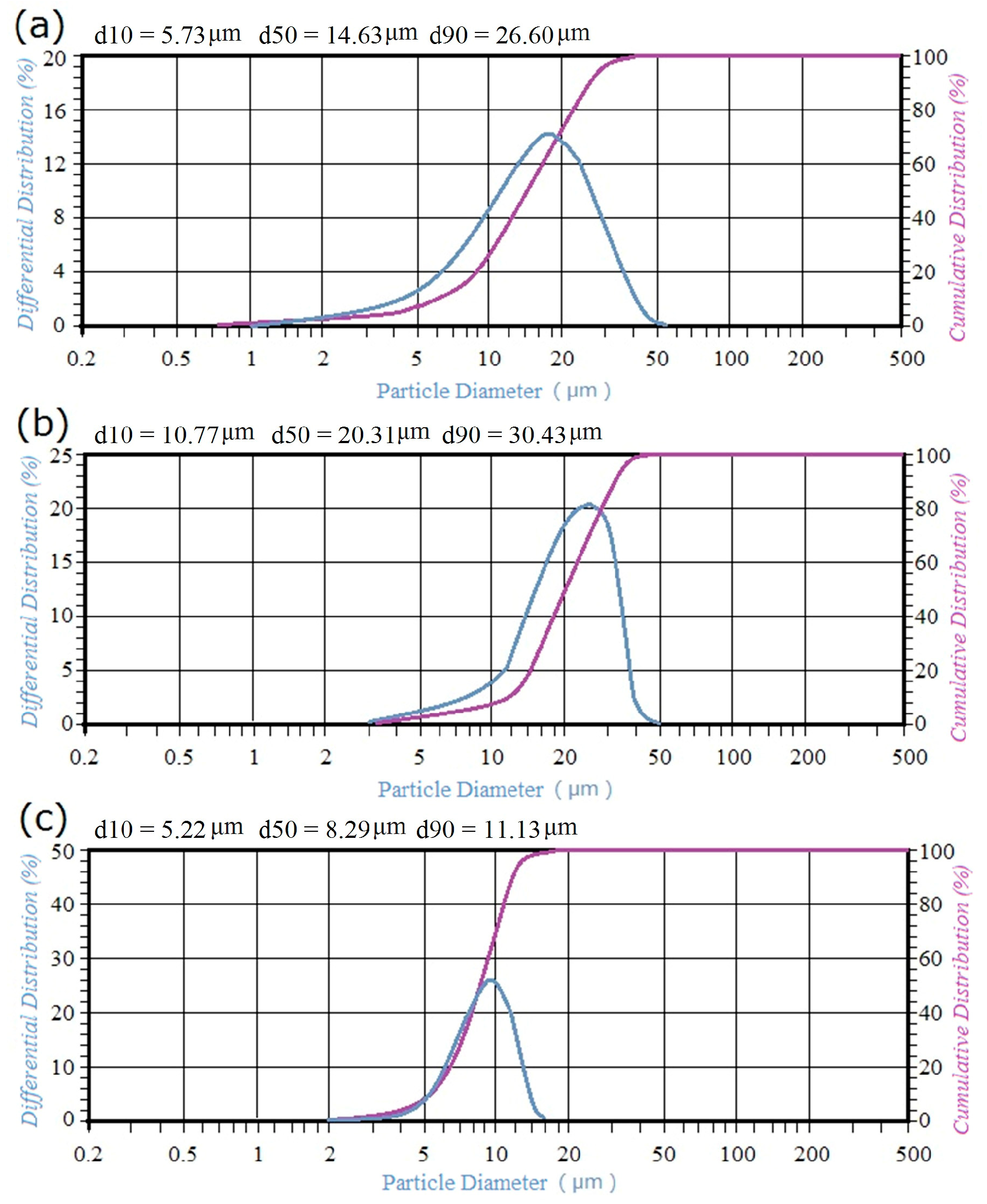
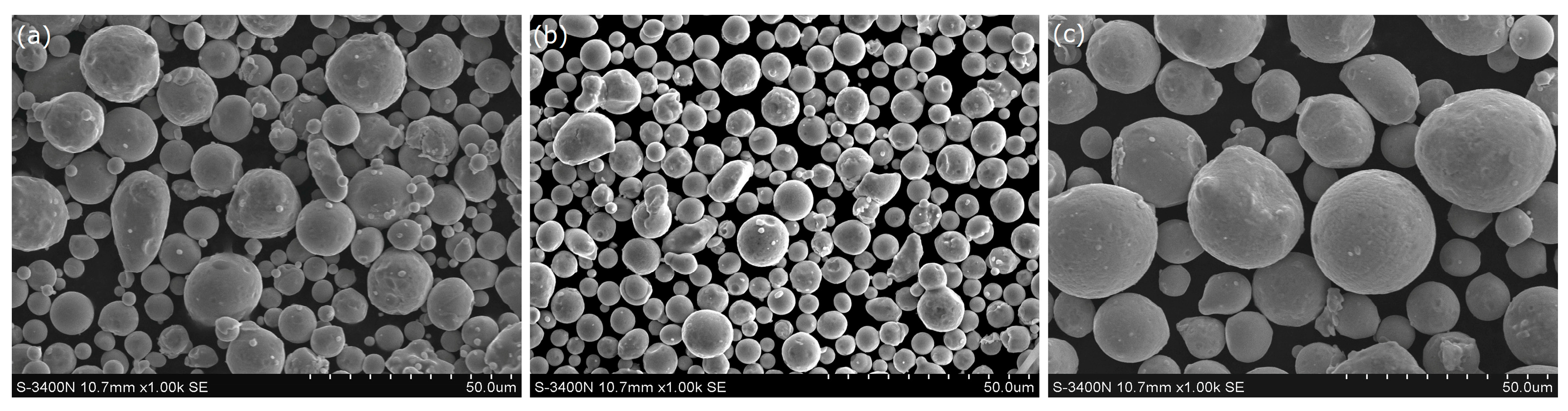
The SS316L nearly spherical powder was gas atomized. Mesh sieving and air classification were adopted to select spherical-shape SS316L powder with three particle size distribution. The particle size distribution analysis was carried out using OMEC LS-POP Particle Size Analyzer (Zhuhai OMEC Instruments Co., Ltd., Zhuhai, China) using laser interferometry. Particle size distribution of three SS316L powders were presented in Figure 1. The size of finer particles is ~16 μm (called fine powder). The size of coarser particles was 4–48 μm (called coarse powder) and the size of raw particles was ~48 μm (called raw powder) with a composition of Fe 66.59 wt. %, Cr 17.26 wt. %, Ni 11.48 wt. %, Mo 2.32 wt. %, Mn 1.41 wt. %, Si 0.71 wt. %, C 0.018 wt. %, and trace amounts of S and P for SLM processing. Three kinds of SS316L powders were characterized using a Hitachi S3400 environmental scanning electron microscope (Hitachi, Tokyo, Japan) for their morphology (Figure 2). The SS316L powders are nearly spherical, but a very small amount of irregular powder can be observed.
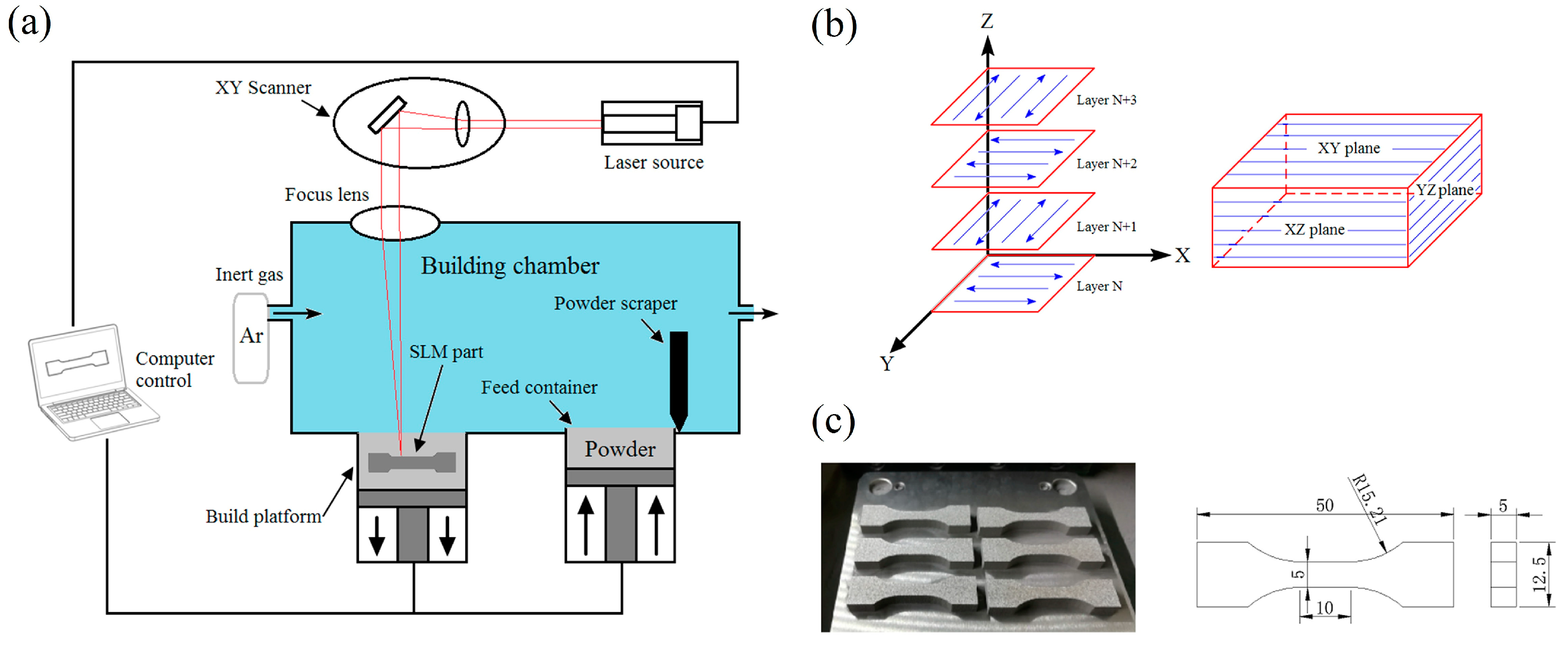
Metallic parts had been produced using the SLM process by the AFS-M120 (Longyuan AFS Co., Beijing, China) with a maximum power of 500 W and a laser spot diameter of 70 μm. Figure 3a schematically illustrates the SLM system. In the experiments, the processing parameters was maintained at the standard settings as recommended by the machine maker (laser power of 200 W, layer thickness of 30 μm, hatch distance of 60 μm, scanning speed of 2000 mm/s and the scan strategy as showed in Figure 3b, Longyuan AFS Co., Beijing, China) at a high-purity Ar atmosphere containing no more than 100 ppm environment oxygen. The laser energy density (total energy input per volume of each track), E (J/mm3), can be calculated by [32]:
where P is the incident laser power, v is the scanning speed, L is the layer thickness, and H is the hatch distance. The E value can then be determined as approximately 55.6 J/mm3.
The density of SLM samples was measured using the Archimedes principle, which can measure the mean density of any sample with complex geometry. The masses of SLM samples were measured independently in air and subsequently in deionised water (ASTM B962-15). Five independent trials were conducted under the same conditions. Relative density (RD) was calculated through the relation [33]:
where m0 is the samples’ mass (g) in air, m1 is the samples’ mass (g) in water, ρwater is the density of deionised water which was 0.9982 g/cm3, and ρ1 is the density of standard steel which is 7.98 g/cm3.
Microhardness was measured by using an HVS-1000 Digital Micro Vickers Hardness (HV) Tester (Shidai Shanfeng Technology Co., Beijing, China) with a test load of 100 gf and a dwell time of 20 s (ASTM E384-17). The flat dogbone specimens (Figure 3c) were SLM-processed in horizontal and had a gauge section of dimensions 10 mm × 5 mm × 5 mm. The tensile tests such as ultimate tensile strength (UTS), yield strength (YS) and elongation (EL) were measured by AG-20k NICD Shimadzu Precision Universal Tester (Shimadzu, Kyoto, Japan) with a test load of 16 kN and a crosshead speed of 1.0 mm/min (ASTM E8/E8M-2013a). Five independent trials were conducted under the same conditions.
Metallographic specimens were cut from the SLM parts using an electric discharge wire and ground with a series of silicon carbide (SiC) sandpapers (400, 800, 1200 and 2000 grit) by using a grinder-polisher machine (YMP-2, Shanghai, China). After plane grinding, polishing was done for samples with Cr2O3 suspension from 5 μm down to 1 μm to achieve a mirror finish. And then chemically etched by a solution (10 mL HNO3, 10 mL HCl and 50 mL H2O) for 30 s at room temperature. The microstructures were observed by TM-1000 scanning electron microscope (Hitachi, Tokyo, Japan) (low magnification) and QUANTA FEG 250 scanning electron microscope (Thermo Fisher Scientific, Eindhoven, The Netherlands) with an Energy Dispersive Spectrometer microanalysis (higher magnification).
3. Results and Discussion
3.1. Relative Density
Relative density of SLM part is a major quality measure that determines the availability of components. Taking 7.98 g/cm3 as the reference value of SS316L, the SLM SS316L samples from fine powder, coarse powder and raw powder achieved a relative density of 97.92 ± 0.13%, 97.00 ± 0.01% and 97.22 ± 0.01%, respectively. The result confirms that the use of powders with fine granulometry could achieve better densification of SLM metal parts than coarse grades by means of achieving the complete melting of powders [34]. Because of the large specific surface area of fine powder, it is favourable to densification of SLM part by increasing the absorption of laser energy [35,36]. Wang et al. [16] investigated the effect of different exposure times, point distance and hatch distance on relative density in SLM SS316L parts. A maximum of 99.99% relative density was reported using the 316L powder with a size range of 5–40 μm, the scanning speed range of 187.5–250 mm/s, the hatch distance range of 120–360 μm and the layer thickness of 150 μm. Lower scanning speed is beneficial to complete melting of fine powder under high layer thickness. When the layer thickness is very low, lower scanning speed will lead to fine powder vaporisation occurrence [37]. Obviously, increasing the thickness of the layer can also shorten the processing time, improve the processing efficiency and reduce the cost. In order to maintain the processing efficiency, the density of the SLM sample could be improved by increasing the laser power. Additionally, it has been proved that the optimized scanning strategy can increase the density of SLM samples by Kruth et al. [38]. Besides, the equipment factor is also one of the reasons for the difference in relative density in SLM process [10,12,20].
3.2. Topography of Top Surface
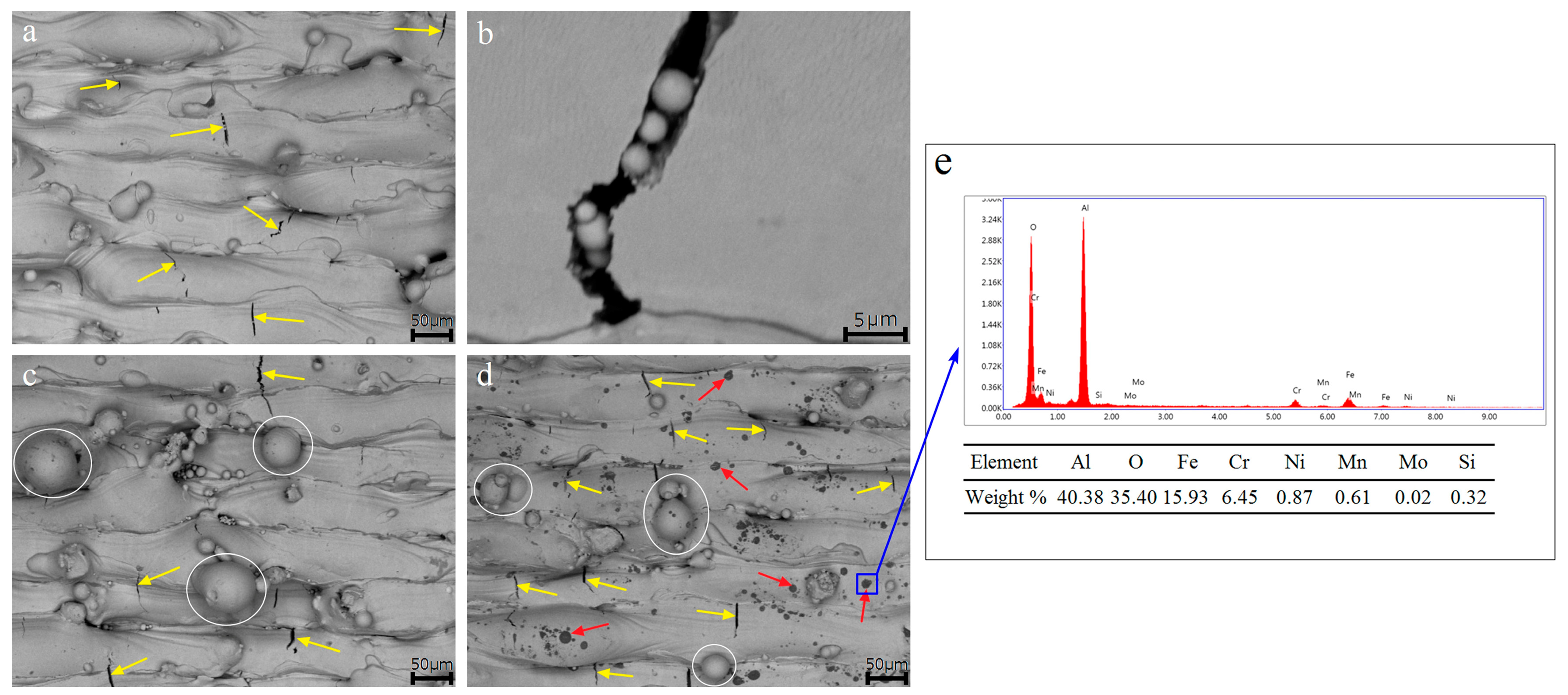
Figure 4 shows the topography of top surface of SLM samples from three particle size distribution of SS316L powders. It can be seen that the sample from fine powder has less un-melted powders sticking on the surface but also containing micro-cracks with a maximum length about 30 μm indicated yellow arrows, compare to samples from coarse powder and raw powder, whose surface have some un-melted powders (white cycles) with diameter of 20–60 μm as showed in Figure 4c,d. And fine spherical powders with diameter less than 5 μm inside the micro-crack of sample from fine powder are observed as showed in Figure 4b. The un-melted powders come from two aspects, one is the larger powder particle with diameter more than 20 μm in raw materials, the other is the balling phenomenon, which is mainly caused by excessive scanning speed in this study. Balling is strongly influenced by the temperature of both the molten powder particles and solid surface [13]. The temperature will be influenced by the energy imparted to the metal powders and is directly related to the particle size distribution of powder explored in this study. The micro-cracks of the SLM part can be attributed to the thermal deformation and residual stress during the SLM process. The SLM is a rapid heating and rapid cooling process. In the solidification process, there is not enough liquid metal to supplement the solidification region. In the subsequent cooling shrinkage process, the solidification region is restrained by the surrounding colder substrate, and the formed residual stress is often difficult to be released, and it will crack if the residual stress released [39]. In the process of SLM, the residual stress is caused by the thermal expansion coefficient, the elastic modulus and the temperature gradient in the laser molten pool area are the root causes of the crack formation. Meanwhile, the micro-stress is caused by the composition of the cladding layer and the tissue gradient leads to the crack propagation. Reducing the scanning speed could decrease the un-melted powders. The micro-cracks of the SLM part could be prevented by shorting the hatch distance [40]. However, these measures would increase the processing time significantly. Optimizing the scanning strategies could reduce thermal stress and reduce the tendency of cracks [41]. Adherent non-metals substances (red arrows) on surface of SLM sample from the raw powder were observed in Figure 4d. Non-metals substances are mainly Al2O3 as showed in Figure 4e. This is one of the reasons for the low density of SLM sample from the raw powder.
3.3. Microstructure of SLM Samples
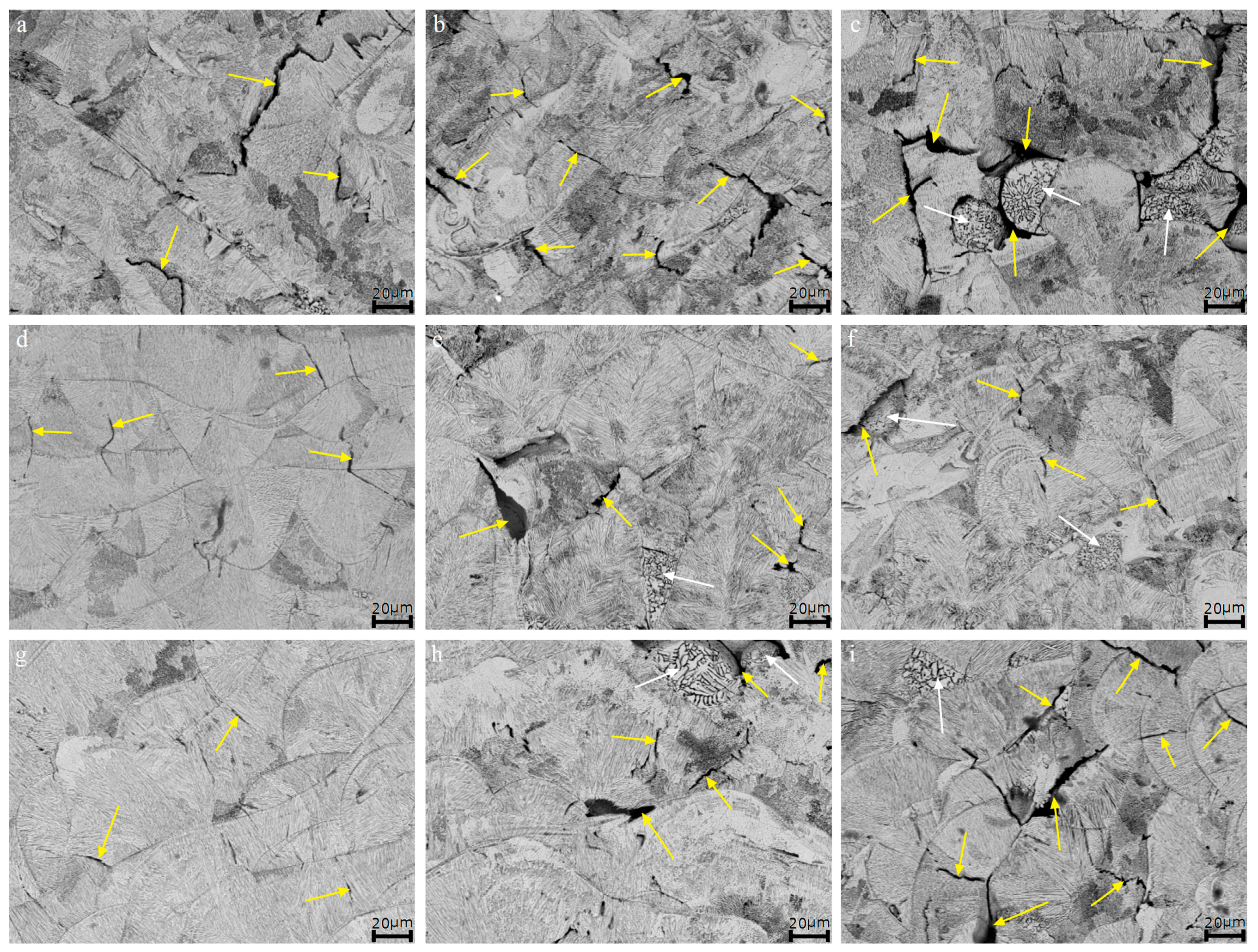
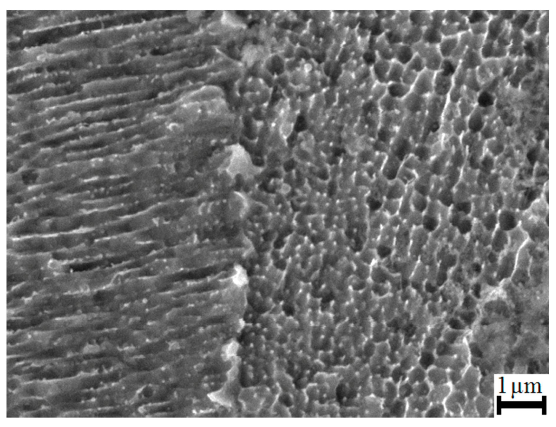
Figure 5 shows the three cross-sectional views of SLM samples from three particle size distribution of SS316L powders. The XY plane is scanning direction, and YZ and XZ planes are building direction. The microstructure of all nine etched SLM samples consists of dendritic structure and cellular structure (Figure 6) with the sizes of the sub-grains are less than 0.5 μm. The number of cellular structure on XY plane is obviously more than that on XZ and YZ planes. The microstructure on XZ and YZ planes is mostly made up of the dendritic structure. Yusuf et al. [10] and Cherry et al. [13] have observed the same microstructure in SLM SS316L parts. Such a structure can be attributed to rapid solidification due to high cooling rates in the SLM processing [5]. On XY plane, there are obviously a lot of micro-cracks (yellow arrows) with a maximum length about 50 μm inner three SLM samples as showed in Figure 5a–c. From Figure 5d–i it can be seen that the curved “fish-scale”-like geometries on YZ and XZ planes is caused by the partial remelting of the semicircular shape of the molten pool and the solidified continuous sedimentary layer [42]. It’s similar to the work carried out by Yusuf et al. [10] and Cherry et al. [13]. It can be observed in Figure 5 that the defects in SLM SS316L samples from three particle size distribution powders are different. In the two planes of SLM samples from coarse powder and raw powder, incomplete fusion (white arrows) and some micro-cracks with length of 20–30 μm (yellow arrows) are observed as showed in Figure 5e,f,h,i. In contrast, there are almost no binding defects on two planes of SLM samples from fine powder. Binding defects are likely generated by incomplete melting of larger particles in the coarse and raw powders [14]. It can be removed by optimizing process parameters to achieve complete melting of large particles, such as increasing laser power or reducing scanning speed.
3.4. Microhardness Measurements
In Table 1, microhardness values of SLM SS316L specimens from fine powder, coarse powder and raw powder on XY, XZ and YZ planes are given. Microhardness values of SLM samples from coarse powder and raw powder on XY plane is higher than other two planes which had similar HV values, similarly to what has been reported by Yusuf et al. [10]. This is because of the scan strategy in SLM processes, which means localised melting of powder particles that often results in non-homogeneous morphologies and anisotropic grain structures [43,44]. However, the microhardness of the fine powder SLM samples at the XY plane is lower than other two planes which had similar hardness values too. This is because of the XY plane contains a lot of micro-cracks, almost no micro-crack in the XZ and YZ plane, as showed in Figure 5a–c. In this study, microhardness values of all SLM SS316L samples are higher than that of the standard bulk SS316L (185 HV) and other researches about SLM SS316L [10,11,12,13,14,21]. The reasons for this result are as follows:
(i) laser energy density is different. Liverani et al. [14] showed that the grain size was larger at higher laser energy density. An increase in laser energy density from 102.0 to 153.1 J/mm3 resulted in hardness values of SLM SS316L sample decreasing from 240 to 230 HV1.
(ii) the printing substrate was not pretreated during processing and the SLM sample was not used for trial post-processing stress-relieving. The range of microhardness value was 216–221 HV1 when the SLM SS316L sample was stress-relieved at 800 °C/5 h conditions [21].
3.5. Mechanical Properties
Tensile properties such as UTS, YS, and EL of three different SLM SS316L samples from the fine powder, coarse powder and raw powder are listed in Table 2. Learn from Table 2, as the SS316L SLM samples was from fine powder, the highest UTS of 611.9 ± 9.4 MPa and YS of 519.1 ± 5.9 MPa and the largest EL of 14.6 ± 1.9% were obtained and practically fitted into the range of values obtained in [14,15,16,17,20]. Ours are slightly lower in EL, which might be due to a higher hardness. The high strength and ductility of the SLM sample from fine powder can be rationalized by considering there are less pores inner the sample as showed in Figure 5. The residual pores often leads to the degradation of mechanical properties [45]. Comparison of process parameters of SLM samples with mechanical properties values given in the references [11,18,19,21] shows a tendency of higher UTS, YS and EL along with lower laser scanning speed (187.5–800 mm/s) with fewer pores in microstructure. As other processing parameters are fixed, a higher laser energy density can be obtained by decreasing the scanning speed. So as to reduce the porosity of the SLM sample. However, the higher laser scan speed can increase the processing efficiency and reduce the processing cost without significantly decreasing the SLM sample’s mechanical properties. The influence of the preheating temperature on the mechanical properties of the SLM SS316L parts was investigated by Zhang et al. [20]. The results showed that the preheating temperature played an important role in the SLM process.
3.6. Fractography
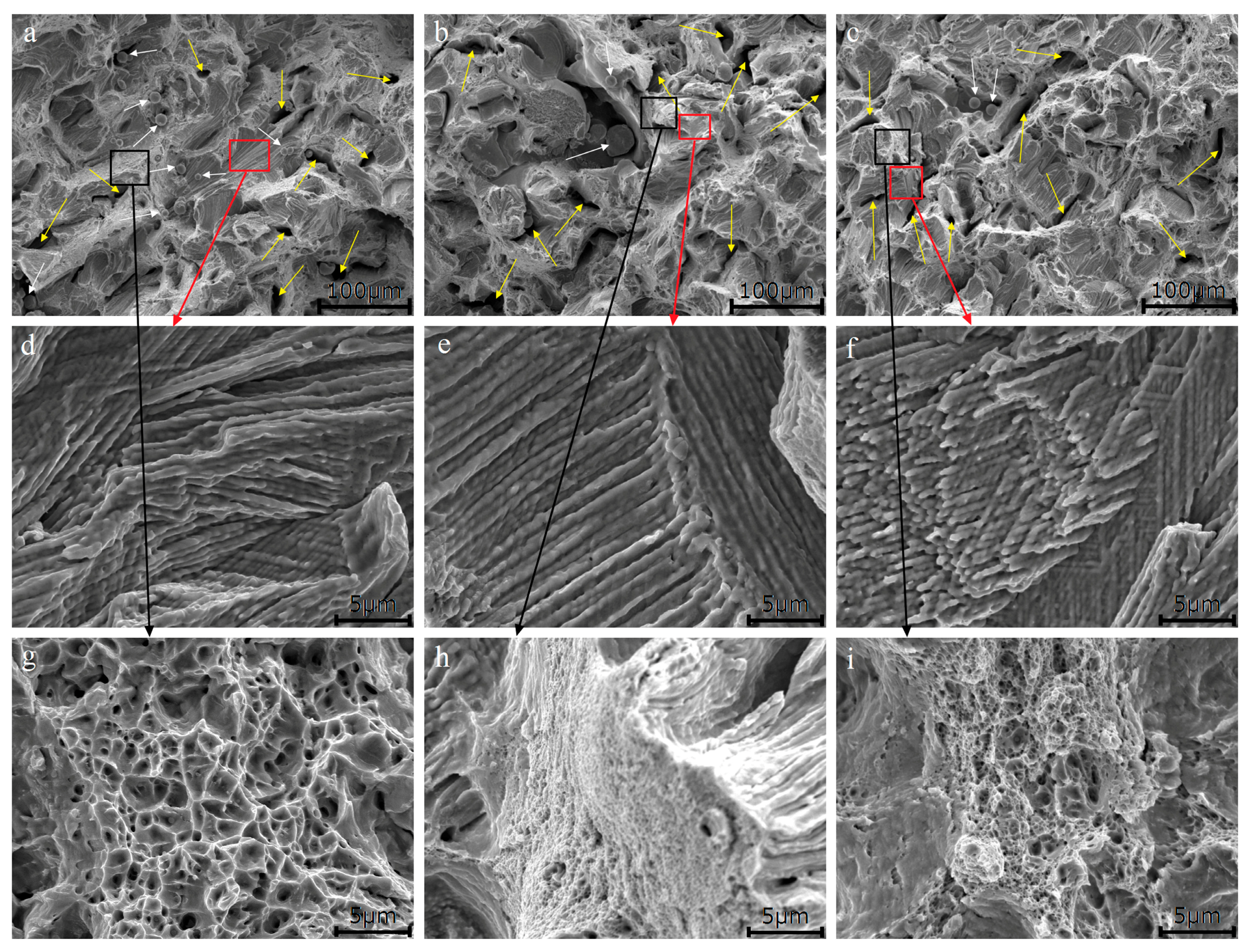
SEM images exposed upon the fracture surfaces of the three tensile samples are summarized in Figure 7a–c at low magnifications, indicating the feature of brittle fracture. In relation to binding defects, irregular voids (yellow arrows) associated with un-melted powder (white arrows) were observed, in line with similar observations by Liverani et al. [14] and Zhong et al. [15]. The un-melted powder in the sample from the fine powder was dropped into the crack and unable to be scanned by the laser beam (Figure 4b). The formation mechanism of un-melted powder in samples from coarse powder and raw powder related to too fast scanning speed during the SLM process, which would lead to larger particles incomplete melting or balling. At higher magnification, the cleavage surface morphology of the three samples was almost the same, and sub-grain structure was shown (Figure 7d–f); and very fine dimples, typical of ductile failure, were observed (Figure 7g–i). The sample from the fine powder has the largest of dimple with diameter of 1–2 μm, the sample from the coarse powder is the smallest with diameter less than 0.5 μm, and the sample from the raw powder is 0.5–1 μm. It is the reason of the best ductility of the sample from the fine powder.
4. Conclusions
In this study, samples of SS316L were fabricated by SLM from three particle size distribution of SS316L powders via a gas atomization system. Through the experimental results, microstructures and mechanical properties of SLM samples of SS316L are affected by powder feedstock. The dendritic structure and cellular structure in all of SLM samples are observed from SEM analysis. The SLM sample from the fine powder (~16 μm) shows the highest UTS of 611.9 ± 9.4 MPa and YS of 519.1 ± 5.9 MPa and the largest EL of 14.6 ± 1.9%, and whose relative density and microhardness reaches a maximum of 97.92 ± 0.13% and 291 ± 6 HV. The findings would be a valuable instruction for selection the size of raw materials in SLM processing and reduce the waste of materials.
Author Contributions
Conceptualization, W.C. and G.Y. Funding acquisition, G.Y.; Investigation, W.C., Z.F. and X.L.; Writing-original draft, W.C.
Funding
This research was funded by the Research and Development Program of Sichuan Province (15ZC0370).
Acknowledgments
The authors are grateful to the Research and Development Program of Sichuan Province (15ZC0370) for the financial support of this work.
Conflicts of Interest
The author declares no conflict of interest.
References
- Attar, H.; Calin, M.; Zhang, L.C.; Scudino, S.; Eckert, J. Manufacture by selective laser melting and mechanical behavior of commercially pure titanium. Mater. Sci. Eng. A 2014, 593, 170–177. [Google Scholar] [CrossRef]
- Attar, H.; Bönisch, M.; Calin, M.; Zhang, L.C.; Scudino, S.; Eckert, J. Selective laser melting of in situ titanium-titanium boride composites: Processing, microstructure and mechanical properties. Acta Mater. 2014, 76, 13–22. [Google Scholar] [CrossRef]
- Attar, H.; Prashanth, K.G.; Zhang, L.C.; Calin, M.; Okulov, I.V.; Scudino, S.; Yang, C.; Eckert, J. Effect of Powder Particle Shape on the Properties of In Situ Ti-TiB Composite Materials Produced by Selective Laser Melting. J. Mater. Sci. Technol. 2015, 31, 1001–1005. [Google Scholar] [CrossRef]
- Attar, H.; Ehtemam-Haghighi, S.; Kent, D.; Dargusch, M.S. Recent developments and opportunities in additive manufacturing of titanium-based matrix composites: A review. Int. J. Mach. Tool. Manuf. 2018, 133, 85–102. [Google Scholar] [CrossRef]
- Lu, Y.J.; Wu, S.Q.; Gan, Y.L.; Huang, T.T.; Yang, C.G.; Lin, J.J.; Lin, J.X. Study on the microstructure, mechanical property and residual stress of SLM Inconel-718 alloy manufactured by differing island scanning strategy. Opt. Laser Technol. 2015, 75, 197–206. [Google Scholar] [CrossRef]
- Kuo, Y.L.; Horikawa, S.; Kakehi, K. Effects of build direction and heat treatment on creep properties of Ni-base superalloy built up by additive manufacturing. Scripta Mater. 2017, 129, 74–78. [Google Scholar] [CrossRef]
- Nandwana, P.; Elliott, A.M.; Siddel, D.; Merriman, A.; Peter, W.H.; Babu, S.S. Powder bed binder jet 3D printing of Inconel 718: Densification, microstructural evolution and challenges. Curr. Opin. Solid State Mater. 2017, 21, 207–218. [Google Scholar] [CrossRef]
- Wang, X.B.; Speirs, M.; Kustov, S.; Vrancken, B.; Li, X.P.; Kruth, J.P.; Humbeeck, J.V. Selective laser melting produced layer-structured NiTi shape memory alloys with high damping properties and Elinvar effect. Scripta Mater. 2018, 146, 246–250. [Google Scholar] [CrossRef]
- Popovich, A.; Sufiiarov, V.; Polozov, I.; Borisov, E.; Masaylo, D.; Orlov, A. Microstructure and mechanical properties of additive manufactured copper alloy. Mater. Lett. 2016, 179, 38–41. [Google Scholar] [CrossRef]
- Yusuf, S.M.; Chen, Y.F.; Boardman, R.; Yang, S.F.; Gao, N. Investigation on Porosity and Microhardness of 316L Stainless Steel Fabricated by Selective Laser Melting. Metals 2017, 7, 64. [Google Scholar] [CrossRef]
- Luo, J.P.; Jia, X.; Gu, R.N.; Zhou, P.; Huang, Y.J.; Sun, J.F.; Yan, M. 316L Stainless Steel Manufactured by Selective Laser Melting and Its Biocompatibility with or without Hydroxyapatite Coating. Metals 2018, 8, 548. [Google Scholar] [CrossRef]
- Sun, Z.J.; Tan, X.P.; Tor, S.B.; Yeong, W.Y. Selective laser melting of stainless steel 316L with low porosity and high build rates. Mater. Des. 2016, 104, 197–204. [Google Scholar] [CrossRef]
- Cherry, J.A.; Davies, H.M.; Mehmood, S.; Lavery, N.P.; Brown, S.G.R.; Sienz, J. Investigation into the effect of process parameters on microstructural and physical properties of 316L stainless steel parts by selective laser melting. Int. J. Adv. Manuf. Technol. 2015, 76, 869–879. [Google Scholar] [CrossRef]
- Liverani, E.; Toschi, S.; Ceschini, L.; Fortunato, A. Effect of selective laser melting (SLM) process parameters on microstructure and mechanical properties of 316L austenitic stainless steel. J. Mater. Process. Technol. 2017, 249, 255–263. [Google Scholar] [CrossRef]
- Zhong, Y.; Liu, L.F.; Wikman, S.; Cui, D.Q.; Shen, Z.J. Intragranular cellular segregation network structure strengthening 316L stainless steel prepared by selective laser melting. J. Nucl. Mater. 2016, 470, 170–178. [Google Scholar] [CrossRef]
- Wang, D.; Song, C.H.; Yang, Y.Q.; Bai, Y.C. Investigation of crystal growth mechanism during selective laser melting and mechanical property characterization of 316L stainless steel parts. Mater. Des. 2016, 100, 291–299. [Google Scholar] [CrossRef]
- Suryawanshi, J.; Prashanth, K.G.; Ramamurtya, U. Mechanical behavior of selective laser melted 316L stainless steel. Mater. Sci. Eng. A 2017, 696, 113–121. [Google Scholar] [CrossRef]
- Casati, R.; Lemke, J.; Vedani, M. Microstructure and fracture behavior of 316L austenitic stainless steel produced by selective laser melting. J. Mater. Sci. Technol. 2016, 32, 738–744. [Google Scholar] [CrossRef]
- Wang, S.; Liu, Y.D.; Shi, W.T.; Qi, B.; Yang, J.; Zhang, F.F.; Han, D.; Ma, Y.Y. Research on High Layer Thickness Fabricated of 316L by Selective Laser Melting. Materials 2017, 10, 1055. [Google Scholar] [CrossRef] [PubMed]
- Zhang, B.C.; Dembinski, L.; Coddet, C. The study of the laser parameters and environment variables effect on mechanical properties of high compact parts elaborated by selective laser melting 316L powder. Mater. Sci. Eng. A 2013, 584, 21–31. [Google Scholar] [CrossRef]
- Kurzynowski, T.; Gruber, K.; Stopyra, W.; Kuźnicka, B.; Chlebus, E. Correlation between process parameters, microstructure and properties of 316 L stainless steel processed by selective laser melting. Mater. Sci. Eng. A 2018, 718, 64–73. [Google Scholar] [CrossRef]
- Cyr, E.; Asgari, H.; Shamsdini, S.; Purdy, M.; Hosseinkhani, K.; Mohammadi, M. Fracture behaviour of additively manufactured MS1-H13 hybrid hard steels. Mater. Lett. 2018, 212, 174–177. [Google Scholar] [CrossRef]
- Xin, X.Z.; Xiang, N.; Chen, J.; Wei, B. In vitro biocompatibility of Co–Cr alloy fabricated by selective laser melting or traditional casting techniques. Mater. Lett. 2012, 88, 101–103. [Google Scholar] [CrossRef]
- Sears, N.; Dhavalikar, P.; Whitely, M.; Cosgriff-Hernandez, E. Fabrication of biomimetic bone grafts with multi-material 3D printing. Biofabrication 2017, 9, 025020. [Google Scholar] [CrossRef] [PubMed]
- Hao, L.; Dadbakhsh, S.; Seaman, O.; Felstead, M. Selective laser melting of a stainless steel and hydroxyapatite composite for load-bearing implant development. J. Mater. Process. Technol. 2009, 209, 5793–5801. [Google Scholar] [CrossRef]
- Telasang, G.; Majumdar, J.D.; Padmanabham, G.; Manna, I. Wear and corrosion behavior of laser surface engineered AISI H13 hot working tool steel. Surf. Coat. Technol. 2015, 261, 69–78. [Google Scholar] [CrossRef]
- Guo, N.; Leu, M.C. Additive manufacturing: Technology, applications and research needs. Front. Mech. Eng. 2013, 8, 215–243. [Google Scholar] [CrossRef]
- Yang, Y.; Lu, J.; Luo, Z.; Wang, D. Accuracy and density optimization in directly fabricating customized orthodontic production by selective laser melting. Rapid. Prot. J. 2012, 18, 482–489. [Google Scholar] [CrossRef]
- Leuders, S.; Thöne, M.; Riemer, A.; Niendorf, T.; Tröster, T.; Richard, H. On the mechanical behaviour of titanium alloy TiAl6V4 manufactured by selective laser melting: Fatigue resistance and crack growth performance. Int. J. Fatigue 2013, 48, 300–307. [Google Scholar] [CrossRef]
- Kok, Y.; Tan, X.P.; Tor, S.B.; Chua, C.K. Fabrication and microstructural characterization of additive manufactured Ti-6Al-4V parts by electron beam melting. Virtual Phys. Prototyp. 2015, 10, 13–21. [Google Scholar] [CrossRef]
- Simsona, T.; Emmela, A.; Dwarsb, A.; Böhm, J. Residual stress measurements on AISI 316L samples manufactured by selective laser melting. Addit. Manuf. 2017, 17, 183–189. [Google Scholar] [CrossRef]
- Zhou, Y.H.; Lin, S.F.; Hou, Y.H.; Wang, D.W.; Zhou, P.; Han, P.L.; Yan, M. Layered surface structure of gas-atomized high Nb-containing TiAl powder and its impact on laser energy absorption for selective laser melting. Appl. Surf. Sci. 2018, 441, 210–217. [Google Scholar] [CrossRef]
- Suyalatu, X.; Takayoshi, N.; Norio, H.; Hitoshi, S. Microstructure and mechanical properties of Ti-X alloys fabricated by selective laser melting process for new biomaterial devices. In Proceedings of the 10th World Biomaterials Congress, Montreal, QC, Canada, 22 May 2016. [Google Scholar]
- Spierings, A.B.; Levy, G. Comparison of density of stainless steel 316L parts produced with selective laser melting using different powder grades. In Proceedings of the Annual International Solid Freeform Fabrication Symposium, Austin, TX, USA, 3–5 August 2009; pp. 342–353. [Google Scholar]
- Irrinki, H.; Dexter, M.; Barmore, B.; Enneti, R.; Pasebani, S.; Badwe, S.; Stitzel, J.; Malhotra, R.; Atre, S.V. Effects of powder attributes and laser powder bed fusion (L-PBF) process conditions on the densification and mechanical properties of 17-4 pH stainless steel. Jom 2016, 68, 860–868. [Google Scholar] [CrossRef]
- Simchi, A. The role of particle size on the laser sintering of iron powder. Metall. Mater. Trans. B 2004, 35, 937–948. [Google Scholar] [CrossRef]
- Tan, J.H.; Wong, W.L.E.; Dalgarno, K.W. An overview of powder granulometry on feedstock and part performance in the selective laser melting process. Addit. Manuf. 2017, 18, 228–255. [Google Scholar] [CrossRef]
- Kruth, J.P.; Badrossamay, M.; Yasa, E.; Deckers, J.; Thijs, L.; Humbeeck, J.V. Part and material properties in selective laser melting of metals, in 16th International symposium on electromachining (ISEM XVI). In Proceedings of the 16th International Symposium on Electromachining, Shanghai, China, 19–23 April 2010. [Google Scholar]
- Li, R.D.; Shi, Y.S.; Wang, Z.G. Densification behavior of gas and water atomized 316L stainless steel powder during selective laser melting. Appl. Surf. Sci. 2010, 256, 4350–4356. [Google Scholar] [CrossRef]
- Hussein, A.; Hao, L.; Yan, C.Z.; Everson, R. Finite element simulation of the temperature and stress fields in single layers built without-support in selective laser melting. Mater. Des. 2013, 52, 638–647. [Google Scholar] [CrossRef]
- Kruth, J.P.; Deckers, J.; Yasa, E.; Wauthlé, R. Assessing and comparing influencing factors of residual stresses in selective laser melting using a novel analysis method. Proc. Inst. Mech. Eng. Part B J. Eng. Manuf. 2012, 226, 980–991. [Google Scholar] [CrossRef]
- Thijs, L.; Kempen, K.; Kruth, J.P.; Humbeeck, J.V. Fine-structured aluminium products with controllable texture by selective laser melting of pre-alloyed AlSi10Mg powder. Acta Mater. 2013, 61, 1809–1819. [Google Scholar] [CrossRef] [Green Version]
- Wu, A.S.; Brown, D.W.; Kumar, M.; Gallegos, G.F.; King, W.E. An Experimental Investigation into Additive Manufacturing-Induced Residual Stresses in 316L Stainless Steel. Metall. Mater. Trans. A 2014, 45, 6260–6270. [Google Scholar] [CrossRef]
- Thijs, L.; Sistiaga, M.L.M.; Wauthle, R.; Xie, Q.; Kruth, J.P.; Humbeeck, J.V. Strong morphological and crystallographic texture and resulting yield strength anisotropy in selective laser melted tantalum. Acta Mater. 2013, 61, 4657–4668. [Google Scholar] [CrossRef]
- Tapia, G.; Elwany, A.H.; Sang, H. Prediction of porosity in metal-based additive manufacturing using spatial Gaussian process models. Addit. Manuf. 2016, 12, 282–290. [Google Scholar] [CrossRef]
Figure 1.
Size distributions of three kinds of SS316L powders (a) raw powder, (b) coarse powder and (c) fine powder.
Figure 1.
Size distributions of three kinds of SS316L powders (a) raw powder, (b) coarse powder and (c) fine powder.

Figure 2.
SEM image of three particle size distribution of SS316L powders (a) raw powder, (b) fine powder and (c) coarse powder.
Figure 2.
SEM image of three particle size distribution of SS316L powders (a) raw powder, (b) fine powder and (c) coarse powder.

Figure 3.
(a) Schematic of SLM system, (b) scanning strategy and (c) SLM-processed tensile specimens.
Figure 3.
(a) Schematic of SLM system, (b) scanning strategy and (c) SLM-processed tensile specimens.

Figure 4.
SEM images of top surface of three SLM SS316L samples (a) low and (b) high magnification of a crack containing un-melted particles of fine powder, (c) coarse powder, (d) raw powder and (e) microanalysis of the non-metals substances in (d).
Figure 4.
SEM images of top surface of three SLM SS316L samples (a) low and (b) high magnification of a crack containing un-melted particles of fine powder, (c) coarse powder, (d) raw powder and (e) microanalysis of the non-metals substances in (d).

Figure 5.
Microstructures of three SLM SS316L samples at different cross-sections (a) fine powder XY plane, (b) coarse powder XY plane, (c) raw powder XY plane, (d) fine powder YZ plane, (e) coarse powder YZ plane, (f) raw powder YZ plane, (g) fine powder XZ plane, (h) coarse powder XZ plane and (i) raw powder XZ plane.

Figure 6.
SEM image of SLM sample with dendritic structure and cellular structure.

Figure 7.
Fracture morphologies of the tensile test of three SLM SS316L samples at low magnifications (a) fine powder, (b) coarse powder, and (c) raw powder. High magnifications, cleavage plane (d) fine powder, (e) coarse powder, and (f) raw powder. High magnifications, dimple morphology (g) fine powder, (h) coarse powder, and (i) raw powder.


Table 1.
Summary of micro hardness of prior work on SLM SS316L parts and this study.
| Particle Size (μm) | P (W) | v (mm/s) | L (μm) | H (μm) | Microhardness (HV) | Reference |
|---|---|---|---|---|---|---|
| 15–40 | 200 | 1600 | 50 | N/A | XY 262 HV0.1 | [10] |
| XZ 237 HV0.1 | ||||||
| YZ 239 HV0.1 | ||||||
| d50 = 37.2 | 140–290 | 800 | 30 | N/A | 200–245 500N | [11] |
| 20–63 | 380 | 3000 | 50 | 25–120 | 213–220 HV1 | [12] |
| 15–45 | 180 | 557–1670 | 50 | 124 | 235 HV10 | [13] |
| 15–45 | 100, 150 | 700 | 20 | 50, 70 | 210–240 HV1 | [14] |
| d50 = 21.6 | 300 | 700–1200 | 30 | 80 | 251–282 HV0.1 | [16] |
| 20–63 | 100, 200 | 200–220 | 50 | N/A | 247–255 HV0.1 | [21] |
| ~16 | 200 | 2000 | 30 | 60 | XY 276 ± 6 HV0.1 | This study |
| XZ 291 ± 6 HV0.1 | ||||||
| YZ 286 ± 5 HV0.1 | ||||||
| 4–48 | 200 | 2000 | 30 | 60 | XY 281 ± 8 HV0.1 | This study |
| XZ 246 ± 7 HV0.1 | ||||||
| YZ 249 ± 5 HV0.1 | ||||||
| ~48 | 200 | 2000 | 30 | 60 | XY 277 ± 9 HV0.1 | This study |
| XZ 248 ± 10 HV0.1 | ||||||
| YZ 255 ± 10 HV0.1 |
N/A indicates that the parameters values are not available.
Table 2.
Summary of tensile properties of prior work on SLM SS316L parts and this study.
| Particle Size (μm) | P (W) | v (mm/s) | L (μm) | H (μm) | UTS (MPa) | YS (MPa) | EL (%) | Reference |
|---|---|---|---|---|---|---|---|---|
| d50 = 37.2 | 140–290 | 800 | 30 | N/A | 600–700 | N/A | 40–60 | [11] |
| 15–45 | 100, 150 | 700 | 20 | 50, 70 | 575–640 | 420–520 | 30–70 | [14] |
| 10–45 | 200 | ~1000 | 20 | 100 | 594 | 487 | 49 | [15] |
| d50 = 21.6 | 300 | 700–1200 | 30 | 80 | 590 | N/A | 14.5–21.1 | [16] |
| 20–50 | 90 | 1000 | 30 | 150 | 621.7 ± 12 | 511.6 ± 14 | 20.4 ± 3 | [17] |
| d50 = 31 | 200 | 750 | 50 | 110 | 684.7 | 554 | 36.6 | [18] |
| 5–40 | 380 | 187.5–250 | 150 | 120–360 | 550–700 | 450–600 | 39.7–41.8 | [19] |
| d50 = 27 | 100 | 100–300 | 50–100 | 80 | 500–600 | N/A | 10 | [20] |
| 20–63 | 100, 200 | 200–220 | 50 | N/A | 662–750 | 409–517 | 25–32 | [21] |
| ~16 | 200 | 2000 | 30 | 60 | 611.9 ± 9.4 | 519.1 ± 5.9 | 14.6 ± 1.9 | This study |
| 4–48 | 200 | 2000 | 30 | 60 | 589.0 ± 8.9 | 498.9 ± 4.2 | 11.4 ± 2.2 | This study |
| ~48 | 200 | 2000 | 30 | 60 | 597.6 ± 4.0 | 509.8 ± 1.7 | 11.0 ± 1.4 | This study |
N/A indicates that the parameters values are not available.
© 2018 by the authors. Licensee MDPI, Basel, Switzerland. This article is an open access article distributed under the terms and conditions of the Creative Commons Attribution (CC BY) license (http://creativecommons.org/licenses/by/4.0/).
Share and Cite
MDPI and ACS Style
Chen, W.; Yin, G.; Feng, Z.; Liao, X. Effect of Powder Feedstock on Microstructure and Mechanical Properties of the 316L Stainless Steel Fabricated by Selective Laser Melting. Metals 2018, 8, 729. https://doi.org/10.3390/met8090729
AMA Style
Chen W, Yin G, Feng Z, Liao X. Effect of Powder Feedstock on Microstructure and Mechanical Properties of the 316L Stainless Steel Fabricated by Selective Laser Melting. Metals. 2018; 8(9):729. https://doi.org/10.3390/met8090729
Chicago/Turabian StyleChen, Wei, Guangfu Yin, Zai Feng, and Xiaoming Liao. 2018. "Effect of Powder Feedstock on Microstructure and Mechanical Properties of the 316L Stainless Steel Fabricated by Selective Laser Melting" Metals 8, no. 9: 729. https://doi.org/10.3390/met8090729
Note that from the first issue of 2016, this journal uses article numbers instead of page numbers. See further details here.