Joining of γ-TiAl Alloy to Ni-Based Superalloy Using Ag-Cu Sputtered Coated Ti Brazing Filler Foil


1
CEMMPRE, Department of Metallurgical and Materials Engineering, University of Porto, R. Dr. Roberto Frias, 4200-465 Porto, Portugal
2
INEGI-Institute of Science and Innovation in Mechanical and Industrial Engineering, R. Dr. Roberto Frias, 4200-465 Porto, Portugal
3
Centre of Physics, Minho University, Azurém, 4800-058 Guimarães, Portugal
4
CMEMS-UMinho, Department of Mechanical Engineering, Minho University, Azurém, 4800-058 Guimarães, Portugal
*
Author to whom correspondence should be addressed.
Metals 2018, 8(9), 723; https://doi.org/10.3390/met8090723
Submission received: 28 August 2018
/
Revised: 11 September 2018
/
Accepted: 12 September 2018
/
Published: 14 September 2018
(This article belongs to the Special Issue Diffusion Bonding and Brazing of Advanced Materials)
Abstract
:Joining γ-TiAl alloy to Ni-based superalloy Hastelloy using Ag-Cu sputtered coated Ti foil as brazing filler was investigated in this study. Brazing experiments were performed at 900, 950, and 980 °C with a dwelling stage of 10 min in vacuum. The microstructure and the chemical composition of the resulting interfaces were analyzed by scanning electron microscopy (SEM) and by energy dispersive X-ray spectroscopy (EDS), respectively. Sound joints were produced after brazing at 980 °C, presenting a multilayered interface, consisting mainly of Ti-Al and Ti-Ni-Al intermetallics close to the γ-TiAl alloy, and of Ti-rich, Ti-Ni, and Cr-Ni-Mo rich phases near Hastelloy. The hardness of the interface, ranging from around 300 to 1100 HV0.01, is higher than both base materials, but no segregation of either Ag solid solution or coarse intermetallic particles was observed. Therefore, the developed brazing filler also avoids the need to perform post-brazing heat treatments that aim to eliminate detrimental extensive segregation of either soft phases or of hard and brittle compounds.
1. Introduction
Titanium aluminides, mainly the novel γ-TiAl alloys, exhibit attractive properties for several applications in the automotive and aerospace industries [1,2,3,4,5]. In fact, since 2006, γ-TiAl alloys have been used to produce blades for GEnxTM engines [3,5]. However, a limiting factor in integrating these alloys into other applications is the lack of reliable and efficient joining techniques that will also enable to obtain appreciable properties or at least properties equal to the base materials. So, the development of new approaches is essential for the joining of γ-TiAl alloys mainly for dissimilar joints that could contribute to a widespread use of the applications.
The possible methods for bonding γ-TiAl alloys to themselves and to other materials involve brazing, diffusion brazing, diffusion bonding, friction welding, electron beam, and laser welding [6,7,8,9,10,11]. Brazing is a joining process that can offer some advantages over other processes, such as allowing for joining to be processed at relatively low temperature, the possibility of joining wide array of dissimilar materials, and the development of lower residual stresses, and normally the joints exhibit good mechanical properties [9,10,11]. The optimization of brazing parameters, such as brazing temperature, the use of adequate heating apparatus, and the brazing alloy are essential for the success of the joining process and for achieving suitable mechanical properties. Ti-based [9,10] and Ag-based [9,11] filler alloys are the most commonly used for brazing of γ-TiAl alloys. Although Ag-based filler alloys can be used as a buffer for residual stresses, the mechanical properties did not allow for their use above 350–400 °C [12,13]; it is important to note that this temperature is significantly inferior to the service temperature of γ-TiAl alloys.
The joining of lightweight γ-TiAl alloys to other high temperature materials, such as Ni-based superalloys is very attractive, since this can produce complex components that combine the singular properties of both materials. However, bonding these materials is very challenging, since conventional processes are not suitable for the production of joints with adequate properties. As far as brazing is concerned, the poor wettability of Ni-based superalloys by conventional brazing fillers is an additional difficulty that needs to be overcome.
Guedes et al. [14] studied the effects of using Ti-based and Ag-based alloys in brazing a γ-TiAl alloy (Ti-47Al-2Cr-2Nb at.%) to an Inconel 718 Ni-based superalloy (Ni-19Cr-19Fe wt.%). The authors observed that sound joints were obtained at 730 °C while using Ag-27.25Cu-12.5In-1.25Ti (wt.%), at 810 °C using Ag-28.1Cu-0.75Ni (wt.%) and at 1200 °C using Ti-33Ni (wt.%). Although it was possible to reduce the brazing temperature of γ-TiAl alloy/Inconel joints using the Ag-based alloys, the interface presents a central extensive layer essentially consisting of Ag solid solution ((Ag)) and a few Cu solid solution ((Cu)) and Al(Cu,Ni)2Ti particles. The formation of a softer interface, mainly composed of (Ag), can be avoided by replacing the Ag-based alloy by a Ti-based alloy as filler. However, the use of a Ti-based filler required higher brazing temperatures (1200 °C), when a Ti-33Ni filler was used. The main advantage of using a Ti-33Ni filler is to prevent the formation of (Ag) at the interface. However, the resulting joints present an interface characterized by the presence of harder compounds than the base materials. In addition, the required joining temperature was too high, particularly for the new generation of γ-TiAl alloys. The total or partial dissolution the undesirable brittle compounds formed at the interface can be achieved by performing a post-brazing heat treatment. Unfortunately heat treating the joints is not always an industrially viable procedure as it may require extremely long dwell times (several days) and elevated temperatures [15,16], which dramatically raises the final cost of the joining process. Thus, it is essential to develop other approaches that facilitate the joining of γ-TiAl alloys to Ni superalloys at lower temperatures and prevent the extensive formation of (Ag) at the interface.
In this context, the objective of this investigation is centered on the evaluation of the potential use of a novel Ag-Cu sputtered coated Ti brazing filler foil to join a γ-TiAl alloy to Ni-based superalloy Hastelloy. The developed filler allows for taking advantage of the same reactions mentioned in the literature that promote successful bonding (brazing with commercial Ag-Cu alloy), while avoiding the formation of large areas of (Ag) during the process due to the larger central Ti foil and very thin layers of Ag and Cu. The interfacial microstructure that was developed in the course of the bonding process has a significant effect on the mechanical properties of joints [16,17]. During brazing, the filler alloys melt and wet the base materials, promoting reactions, leading to the formation of phases that ensure bonding. The process is diffusion controlled, thus highly temperature dependent. Therefore, in order to understand the effect of the brazing temperature upon the phase formation at the interface, and consequently upon then the mechanical properties of joints, microstructural characterization of the brazed joints is essential. The interfacial microstructural and chemical features of joints were analyzed by scanning electron microscopy (SEM) and by energy dispersive X-ray spectroscopy (EDS), and a reaction mechanism leading to joining was discussed.
2. Materials and Methods
2.1. Materials
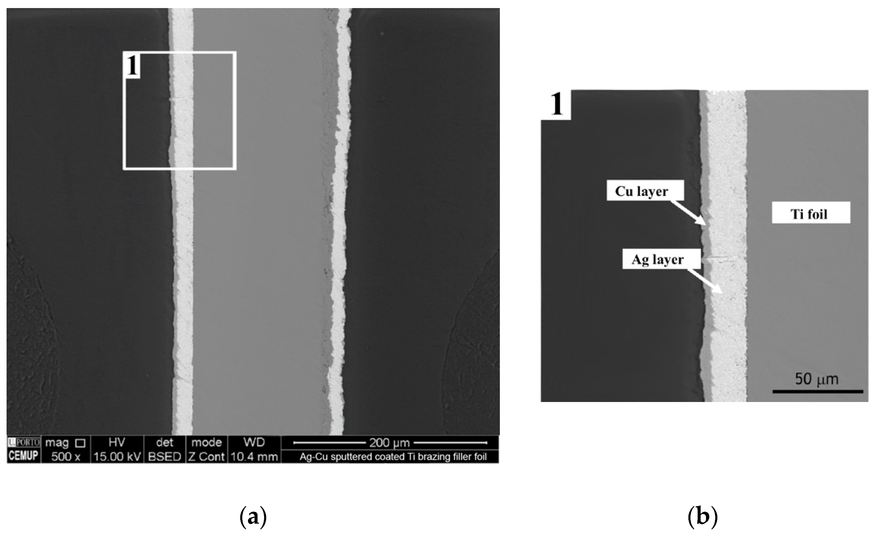
The base materials used in this investigation were a γ-TiAl alloy (Ti-45Al-5Nb (at.%)), with a duplex microstructure consisting of a mixture of single phase γ-TiAl grains and of (α2 + γ) lamellar grains and Ni-based superalloy Hastelloy (Ni-18Cr-11Mo-6.6Fe-3.0Co-1.9W (at.%)). The brazing filler consisted of a Ti foil (150 μm) coated with Ag film, followed by a Cu film. Both of the films were produced by direct current magnetron sputtering (custom setup at Minho University) from Ag and Cu metal targets (purity 99.99%, FHR Anlagenbau GMBH) in an argon plasma, with a base pressure of 10−6 mbar prior to deposition. The goal was to achieve a global chemical composition of the filler of around 95% of Ti and 5% of Ag-Cu (wt.%). Figure 1 shows the backscattered electron images (BEIs) of the as-deposited brazing filler. The thickness of Ag and Cu layers are 18.5 ± 1.6 and 4.5 ± 0.7 μm, respectively.
The melting temperature range of the filler alloy was determined by differential scanning calorimetry (DSC) (TGA & DTA/DSC thermal analyzer, SETARAM Instrumentation, France). The experiments were performed from room temperature to 1000 °C with heating and cooling rates of 5 and 10 °C·min−1 in an argon atmosphere.
2.2. Brazing Experiments
Samples of the γ-TiAl alloy and of Hastelloy with a thickness of 13 mm were cut with a diamond saw to a thickness of 5 mm and then wet ground with SiC paper to a 1200 mesh finish. The sputtered coated Ti brazing filler foil was cut into disks with the same diameter as the samples to be joined. Prior to brazing, all of the materials were degreased in acetone with ultrasonic agitation and dried in air. Brazing was performed in a tubular furnace, which was evacuated by a combination of rotary and turbomolecular pumps to a vacuum level that was better than 10−4 mbar. Joints were processed at 900, 950, and 980 °C with a dwelling stage of 10 min at the processing temperature. Heating and cooling rates were fixed to 5 °C·min−1 by a temperature controller.
2.3. Joints Characterization
Joints for microstructural, chemical and mechanical characterizations were cut perpendicularly to the interface and cold mounted in epoxy resin and then prepared using standard metallographic techniques. A final polishing with a solution of 0.04 µm colloidal silica suspension and hydrogen peroxide ensured the removal of any deformed layer.
2.3.1. Microstructural and Chemical Characterization
The interfaces were observed by optical microscopy (OM) (DM4000; Leica Microsystems, Wetzlar, Germany) and by scanning electron microscopy (SEM). Chemical analysis was performed by energy dispersive X-ray spectroscopy (EDS, Oxford Instruments, Oxfordshire, UK), while using a high-resolution FEI QUANTA 400 FEG SEM (FEI Company, Hillsboro, OR, USA). The EDS measurements were made at an accelerating voltage of 15 keV by the standardless quantification method. The results obtained by this method provide a fast quantification with an automatic background subtraction, matrix correction, and normalization to 100% for all of the elements in the peak identification list.
It is worth mentioning that EDS analysis obviously does not permit the identification of the phases that constitute the interface. However, by using slow heating and cooling rates, it is possible to consider that a quasi-equilibrium state is achieved at the interfaces during the entire thermal cycle. Thus, equilibrium phase diagrams can be used in conjunction with SEM images and EDS analysis to predict the nature of some of the phases that constitute the interface. This approach will be used in the present investigation whenever it is appropriate to do so.
2.3.2. Mechanical Characterization
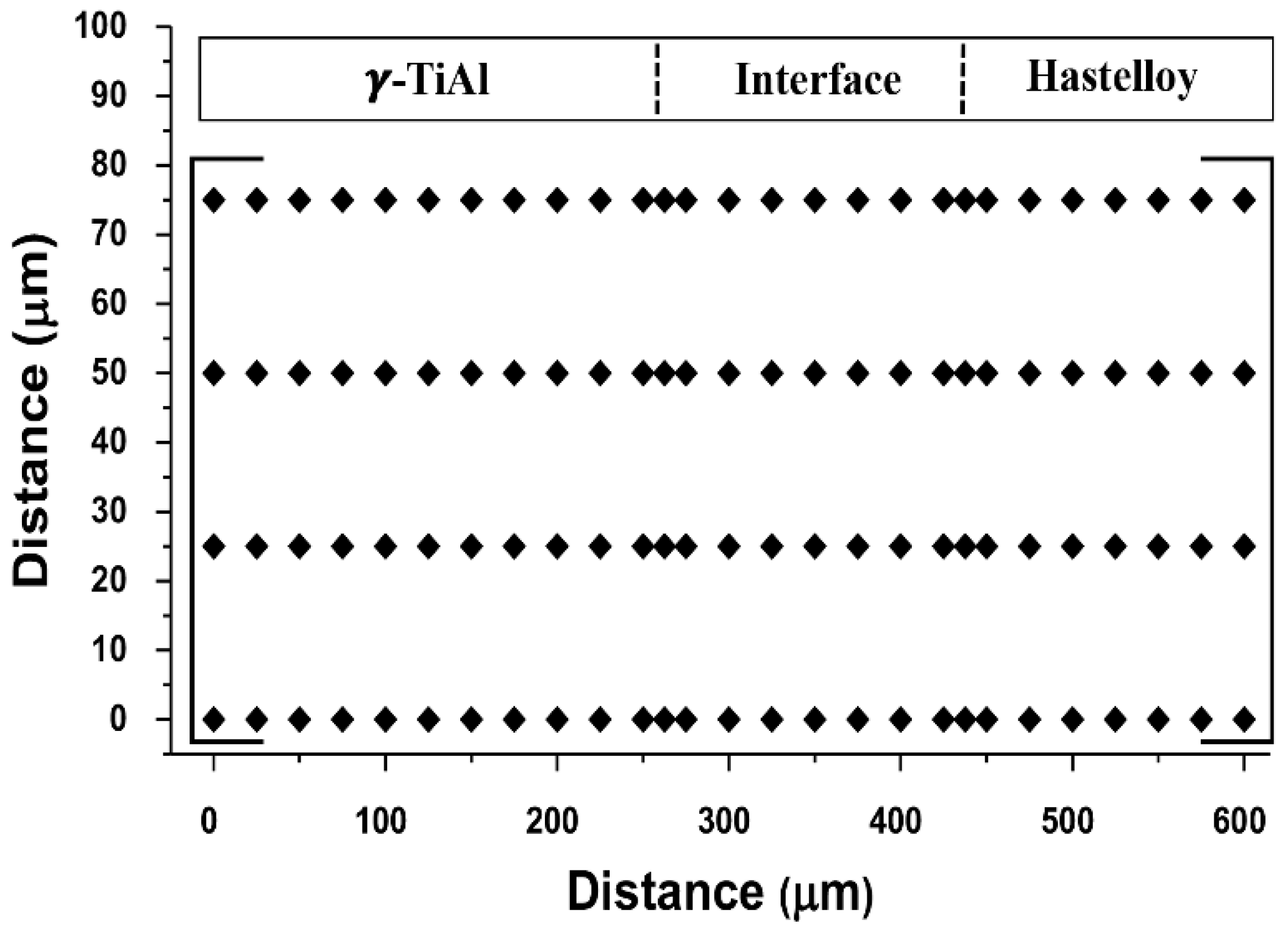
The mechanical behavior was evaluated by Vickers microhardness while using a 98 mN load (Duramin-1, Struers A/S, Ballerup, Denmark). Indentation matrices with a minimum of 100 measurements were selected to test interface and both base materials. The scheme of the matrices across the interface is represented in Figure 2.
3. Results and Discussion
Microstructural chemical and mechanical characterizations were performed in order to evaluate the effectiveness of using the novel Ag-Cu sputtered coated Ti brazing filler to bond Ti-45Al-5Nb (at.%) to Hastelloy. The influence of the brazing temperature on the microstructure and strength of the interface was assessed and the mechanisms leading to bonding were discussed. Unless stated otherwise, all the chemical compositions will be expressed hereafter in at.%.
3.1. Characterization of Ag-Cu Sputtered Coated Ti Brazing Filler
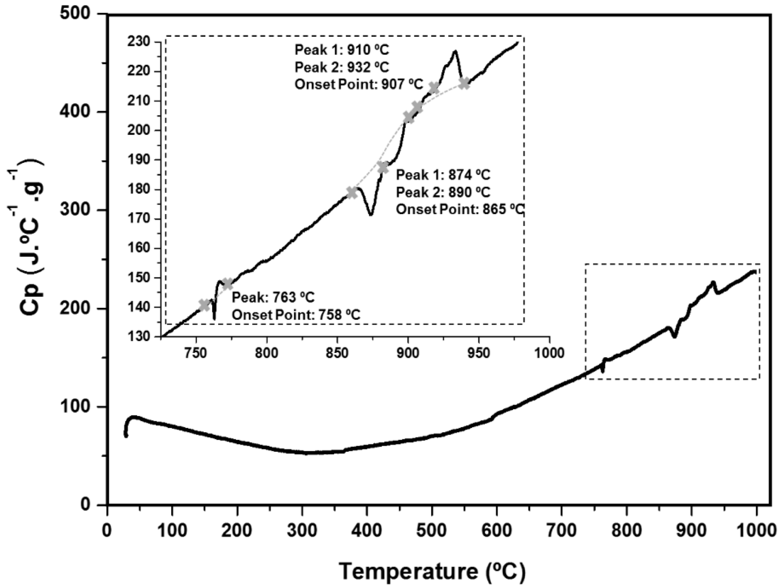
Figure 3 shows the DSC curve for the Ag-Cu sputtered coated Ti brazing filler. In this curve, it is possible to observe three main peaks: two endothermic peaks, with an onset point at 763 °C and at 865 °C and an exothermic peak, with an onset point at 907 °C. However, the peaks that were observed at 865 and 907 °C show sequential and overlapping reactions.
These results are not significantly affected by different heating rates (5 and 10 °C·min−1); the difference was a small increase (lower than 10 °C) in the peak temperatures and for the slower rate it is more evident that there is more than one reaction corresponding to the peaks occurring at higher temperatures. During cooling, it was possible to identify three exothermic reactions, occurring at 972, 931, and 906 °C.
Based on these results, the temperature range that was suitable for the brazing of this alloy would be comprised between 900 and 970 °C. Hence, all reactions associated with the observed peaks in the DSC curves correspond to different phase transformations that will influence the microstructure of the interface when this alloy is applied in bonding processes.
3.2. Microstructural and Chemical Characterization of the Interface
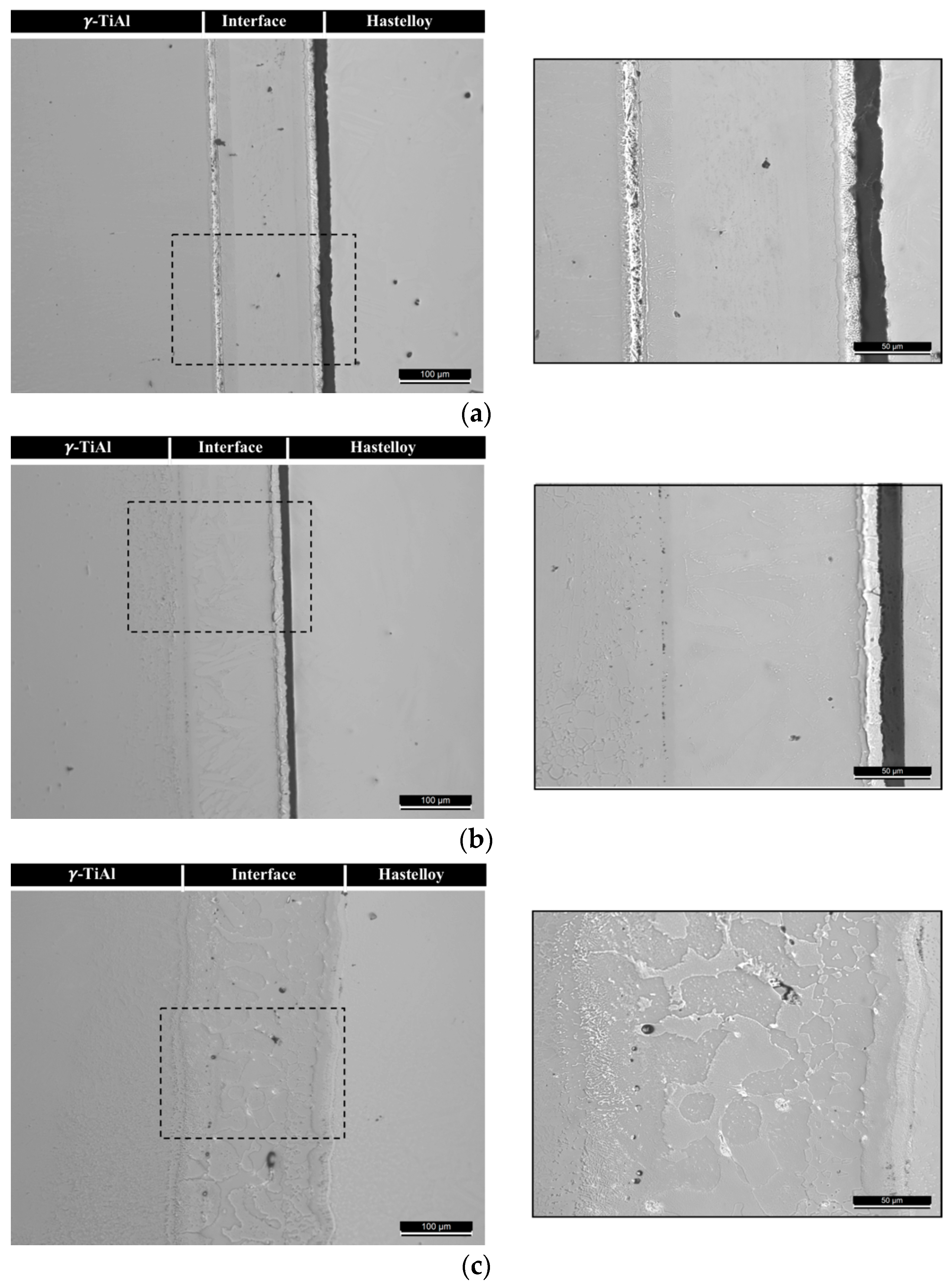
Microstructural characterization reveals that the use of Ag-Cu sputtered coated Ti brazing filler is a suitable approach for the production of γ-TiAl alloy/Hastelloy joints. The results show that the brazing temperature strongly influences the success of the joining process. The brazing experiments carried out at 900 °C were unsuccessful, since the bonding between the base materials was not achieved, as can be observed in the OM images of Figure 4. After processing at this temperature, a few reaction zones have been identified on the γ-TiAl alloy side, contrary to the Hastelloy side of the interface, where bonding was not achieved (Figure 4a). By increasing the brazing temperature to 950 °C, several reaction zones are observed at the interface between the base materials and the brazing filler, and some well-bonded regions are detected on the γ-TiAl side (Figure 4b). However, unbonded zones (mainly on the Hastelloy side) and several defects, such as pores were detected. In fact, in our previous study [18] the same type of defects had already been observed after joining the γ-TiAl alloy to itself, with the same brazing filler being used in this investigation under the same processing conditions. On the other hand, it is possible to join γ-TiAl alloy/Hastelloy, obtaining interfaces without unbonded zones if the brazing temperature is increased to 980 °C (Figure 4c). Although DSC results show that joining may occur between 900 and 970, microstructural analysis shows that brazing should be performed above 950 °C for a dwelling stage of 10 min to produce interfaces without unbonded zones. This clearly shows the temperature dependence of the diffusion controlled brazing process.
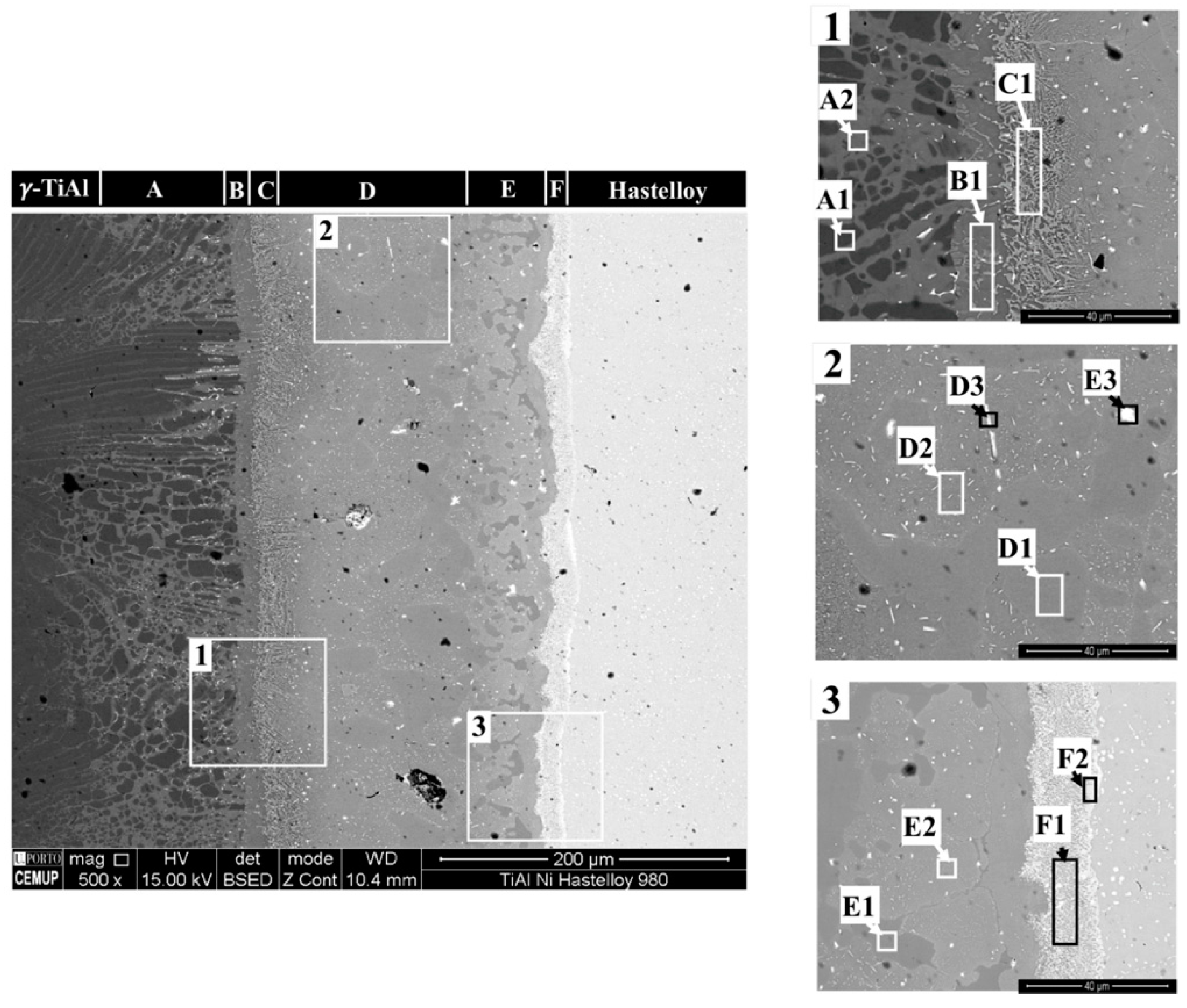
Figure 5 shows the microstructure by SEM of a typical interfacial microstructure of γ-TiAl alloy/Hastelloy joints after processing at 980 °C. The interface exbibits a thickness of 350 µm and could be divided into six different layers, which are identified by the letters A to F in sequence starting from the γ-TiAl alloy side of the interface. Table 1 shows the results of EDS analysis that was performed in different zones of the interface as indicated in the higher magnification SEM images identified as 1, 2, and 3 in Figure 5.
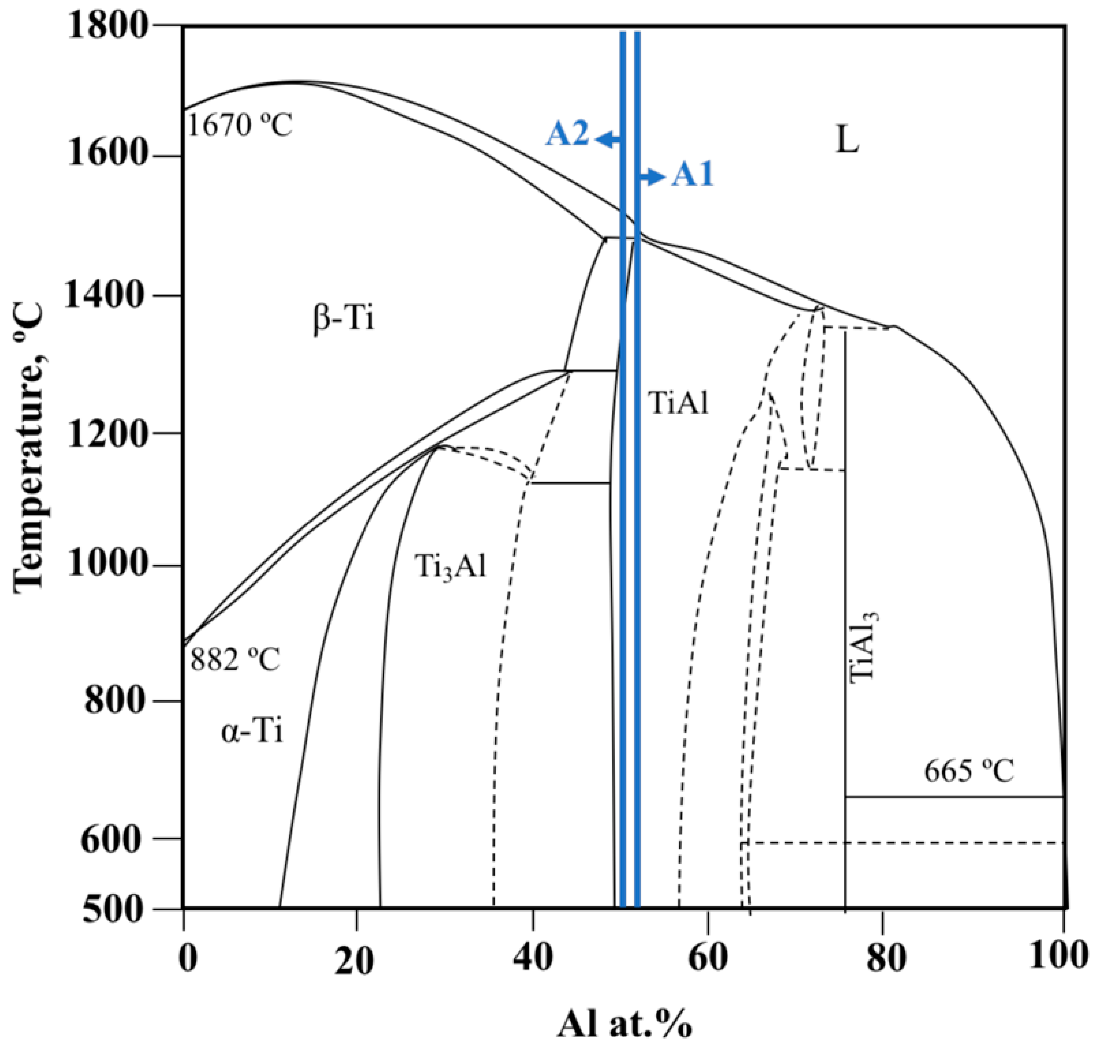
Layer A is a diffusion layer, approximately 100 µm thick, which extends into the γ-TiAl alloy and where Ag and Cu from the sputtered Ti foil are detected. This layer no longer presents a duplex microstructure and it consists mainly of two different zones that are marked as A1 and A2 in the SEM image, corresponding to Region 1 of Figure 5. Both zones are composed of more than 90% of Ti and Al, with Ti:Al atomic ratios of around 0.9 and 1.0, for A1 and A2, respectively. The intermetallic γ-TiAl is stable at 500 °C for atomic ratios of between 0.8 and 1.0 [19] (see Figure 6). Considering that at room temperature the Ti:Al stability ratio range of γ-TiAl is roughly the same as that at 500 °C, then Layer A should be mainly composed of γ-TiAl. Therefore, as a result of the interdiffusion between the γ-TiAl alloy and the filler foil, the α2-Ti3Al phase present in the (α2 + γ) lamellar grains of the duplex microstructure was transformed into γ-TiAl. In the lamellar grains, both the γ-TiAl ”transformed” phase and the “original” γ-TiAl phase dissolved minor amounts of Ag and Cu and they constitute zones labelled as A2. Zone A1 consists of “original” single phase γ-TiAl grains of the duplex microstructure that did not dissolve detectable amounts of either Cu and Ag. In addition, a few thin elongated white particles are observed in this layer that are Ag-rich, but they are also too thin to be adequately analysed by EDS. These particles may consist of (Ag), resulting from the amount of Ag diffused from the filler foil having exceeded the low solubility limit of Ag in both the surrounding γ and α2 phases. In fact, the Ag solubility limit is less than 3 at.% at 800 °C [20] in each of these intermetallics.
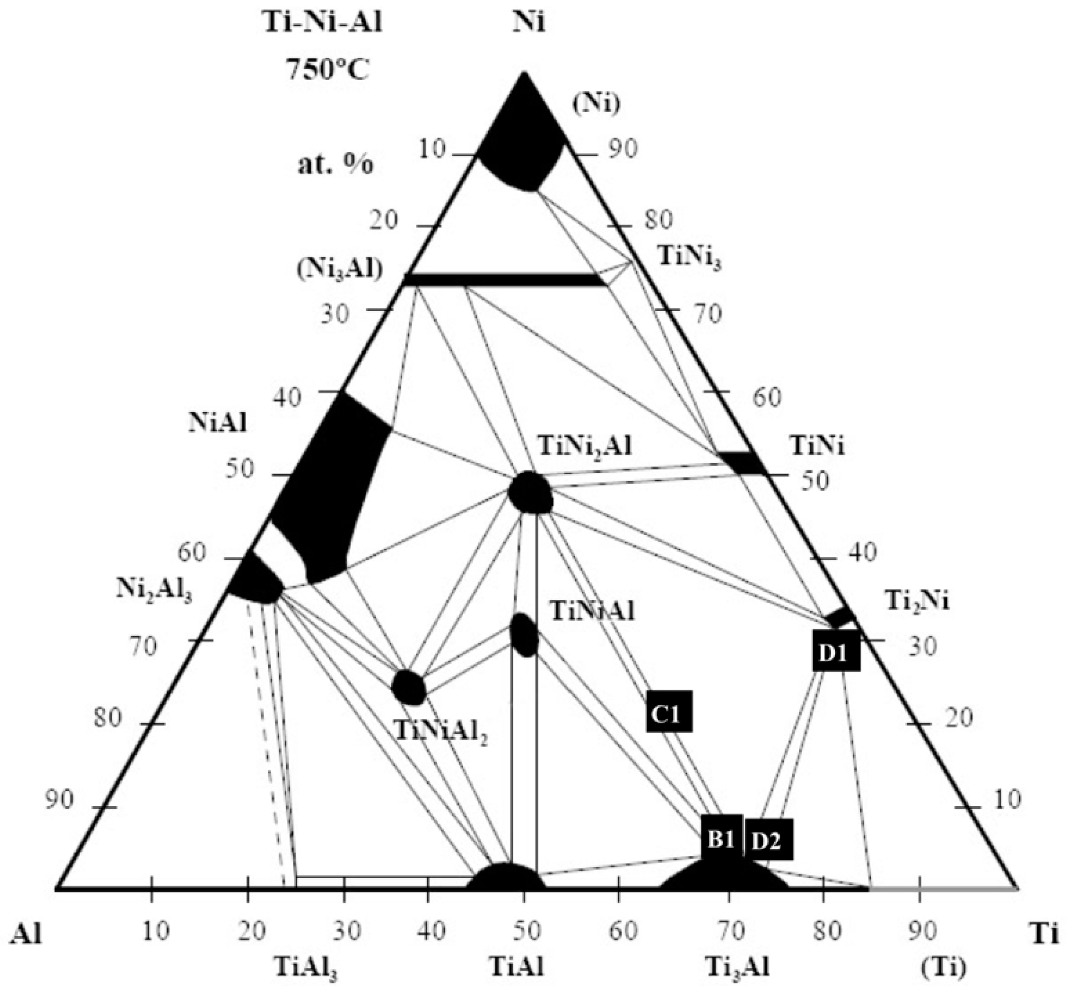
Layer B, with a thickness of around 15 µm, is mainly composed of γ-TiAl zones with the same chemical composition as A2 in Layer A. The BEIs of Figure 5 shows that this layer consists of a mixture of γ-TiAl with a small number of other light grey constituents (zone marked as B1 in the SEM image of Region 1 in Figure 5). EDS analysis indicates that Zone B1 is composed of almost 88% of Al, Ni, and Ti. When considering this chemical composition and the isothermal section at 750 °C of the Al-Ni-Ti [20] ternary phase diagram shown in Figure 7, it can be considered that this layer should be composed of a mixture of γ-TiAl with an α2-Ti3Al intermetallic compound (light grey constituents). It should be noted that within the composition range detected at the interface (i) this isothermal section is the available section closest to room temperature and (ii) no invariant reactions are reported bellow 750 °C. This indicates that the phases that are indicated on the isothermal section should be stable at room temperature.
Layer C is about 20 µm thick and consists of a mixture of thin phases with different greyscale values in the BEI image. This layer delimits the central zone of the interface from Layer B. Similarly, to what was observed in the lighter grey zones of Layer B, almost 88% of the global chemical composition of Layer C (C1 in Table 1 and in the SEM image of Region 2 in Figure 5) corresponds to the sum of Al, Ni, and Ti. However, Layer C exhibits higher Ni and lower Ti content. The global chemical composition of Zone C1 is marked in the isothermal section shown in Figure 7 and corresponds to the two phase TiNi2Al + α2-Ti3Al field, but it is closer to the α2-Ti3Al single-phase field. Thus, it is reasonable to assume that it should be mainly composed of α2-Ti3Al (darker grey zones) and of a lesser amount of TiNi2Al (light grey zones).
Layer D is the widest one of the interface, presenting a thickness of around 140 µm. Three different zones can be observed in this layer, as is shown in Table 1, all presenting a rather complex chemical composition. Darker grey zones (marked as D1 in the SEM image of Region 2 in Figure 5) are mainly composed of Ti and Ni; lighter grey zones (marked as D2) are mainly composed of Ti, Al, and Ni; white zones (marked as D3) are mainly composed of Ti and Ag. According to the EDS results combined with the isothermal section at 750 °C of the Al-Ni-Ti diagram [21], the darker grey zones should correspond to Ti2Ni intermetallic ones, since they are composed of more than 98% of Al, Cu, Ni and Ti and their chemical composition is close to Ti2Ni single phase field (see Figure 7). The α2-Ti3Al and Ti2Ni intermetallics must be the main constituent phases of the lighter grey zones, following the pattern of their typical chemical composition on the isothermal section in Figure 7, as well as to the Ti:Al atomic ratio of 3.9. Indeed, the Ti-Al phase diagram [19] indicates that α2 is stable for Ti:Al atomic ratios comprising between around 4.0 and 1.8 at 500 °C, and additionally their compositional plot on the isothermal section in Figure 7 lays close to the α2-Ti3Al single phase field. Finally, elements from both base materials and from the filler are detected in the white zones, with Ti and Ag being the main elements, with contents of 41.1% and 32.3%, respectively. Roughly the same chemical composition is detected in the white zones, whether they present a globular-like morphology or an elongated shape. Nevertheless, with the techniques used in this investigation, it is not possible to make a reasonable estimation concerning the nature of the main phase that constitutes the Ti-Ag rich white zones observed in Layer D. It is worth mentioning that according to the Al-Ni-Ti phase diagram [20], the main phases in contiguous Layers C (α2-Ti3Al and some TiNi2Al) and D (T2Ni mainly and α2-Ti3Al) may coexist in equilibrium. This supports the assumption that these should be the main phases that are present in Layers C and D.
Layer E is approximately 60 µm and consists of a mixture of darker grey (E1), lighter grey (E2), and white zones (E3). It should be mentioned that Mo, which was not detected in the layers from A to D, is detected in the lighter grey zones of Layer E and that it is also possible to observe very thin white precipitates dispersed in the lighter grey zones. Darker grey zones should be Ti2Ni, since they are mainly composed of Ti and Ni with Ti:Ni atomic ratio around 2. The chemical composition of the lighter grey zones comprises all of the elements detected at the interface, the exception of Nb, with Ti being the main element with contents of around 60%. The high amount of Ti in these zones suggests that the main components may consist of Ti-rich intermetallic phase(s) and/or a Ti solid solution.
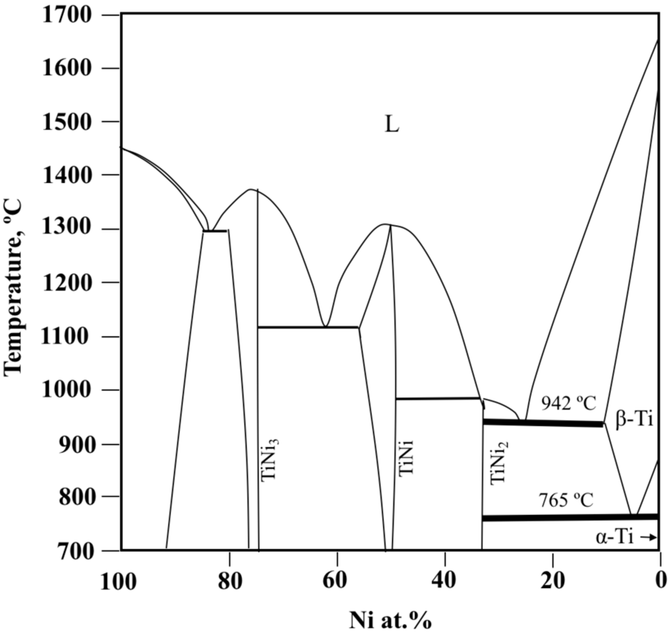
It is important to emphasize that at the central zone of the interface (Layers D and E), Ti2Ni should be one of the major phases, since it may be the main constituent of the darker grey zones and may eventually be one of the phases present in the lighter grey zones. The extensive formation of Ni-rich phases at the centre of the interface indicates that an intense diffusion of Ni into the Ti filler foil has taken place during the brazing thermal cycle. The results that were obtained in this investigation also suggest that when brazing is performed at 980 °C, diffusion of Ni into the Ti filler foil may have induced the formation of a Ti-rich liquid in a zone of the Ti foil corresponding to Layer E, which should be mainly composed of Ti2Ni and other Ti-rich phases. This assumption is corroborated by the analysis of the Ti-Ni equilibrium phase diagram [21], which is presented in Figure 8. Indeed, the diagram shows that β-Ti may coexist in equilibrium with a liquid phase with around 25% of Ni. The liquid will undergo the eutectic reaction upon cooling at 942 °C, forming Ti2Ni and β-Ti. In turn, when reaching 765 °C, β-Ti decomposes into α-Ti and Ti2Ni, in accordance with the eutectoid reaction indicated in the diagram. Thus, although it is a simplified version of the complex brazing system in this study, the Ti-Ni phase diagram underlines diffusion and reaction paths that, in our opinion, constitute the basis of the mechanism that governs the formation of Layer E. Hence, the main phases in the grey zones in Layer E are hipereutectic and/or eutectic Ti2Ni, while in the light grey zones α-Ti and Ti2Ni may be the main phases as the result of the eutectoid decomposition of β-Ti. It should be noted that He et al. [12] processed Hastelloy X joints using Ti foil as filler and found evidence that supports a similar reaction mechanism. They also identified the formation of Ti2Ni and β-Ti at the brazing interface. Finally, EDS analysis indicates that Ti and Ag with a 2:1 atomic ratio are the main elements that are detected in the white zones of Layer E, but it is impossible to make a realistic assessment of the nature of the main phases that constitute the white zones in Layer D.
Layer F exbibits a thickness of 15 µm and it is characterized by a mixture of grey and white zones formed close to Hastelloy that are too thin to enable evaluating their individual compositions by EDS. The global composition of Layer F indicates that it is composed of Ni, Cr Ti, and Mo, with Ni and Ti contents of around 40.8 and 14.5%, respectively (F1 in Table 1). A thin white zone sheath (Zone F2) delimits this layer from the Hastelloy. The white sheath is mainly composed of Ni, Cr, and Mo, presumably as the white zones that are mixed with the grey zones in this layer. He et al. [12] identified a Cr9Mo21Ni20-based phase and a TiNi3 that had formed near the superalloy after Hastelloy X was joined at 1100 °C using a Ti foil. Considering the similarities between the two studies, these results may suggest that Layer F is composed of a mixture of a Cr-Ni-Mo rich phase (white zones) and of a Ni-Ti phase, eventually transforming into TiNi3 (grey zones). Finally, it should be noted that no traces of filler alloy elements were detected in Hastelloy near the interface (Zones H1 and H2). Thus, contrary to the γ-TiAl alloy side of the interface, no diffusion layer was identified on the Hastelloy side.
The results that were obtained in this investigation permit an understanding of some of the mechanisms that govern the establishment of bonding in γ-TiAl alloy/Hastelloy joints brazed with Ag-Cu sputtered coated Ti filler foil. In the course of heating to the brazing temperature, the interdiffusion between the Ag and Cu sputtered films enabled the formation of an Ag-Cu liquid phase. The composition of the liquid will be altered during the remaining joining thermal cycle by mass transport phenomena: (i) dissolution of the base materials and of the Ti foil, and (ii) interdifusion between the liquid and the contiguous solids (Ti foil and each base material sample). The Ag-Cu rich liquid will readily solidify due to the combined effects of dissolution and interdiffusion. Afterwards, the chemical and microstructural features of the forming interface will be mainly controlled by solid state diffusion. The diffusion of Ni into the Ti foil will enable the formation of a Ti-Ni rich liquid near Hastelloy, which will be a determining factor in the microstructural development of the central zones of the interface.
Upon heating to the brazing temperature, as soon as the Ag-Cu liquid forms, it begins to dissolve the Ti foil and the base materials, incorporating mainly Ti, Al, and Ni until the solubility limits in the melt are exceeded. Afterwards, near each base material, precipitates will consolidate into continuous layers, enabling bridging between the base materials and the Ti foil. In addition, and at the same time, interdiffusion throughout the forming interface will be occurring.
On the γ-TiAl alloy side, as the solubility limits of Ti and Al into the molten Ag-Cu rich liquid are exceeded, Ti-Al intermetallic particles precipitate, forming a layer that, as the result of interdiffusion between the base γ-TiAl alloy and the remaining Ti filler foil, will consolidate into Layer B, which is composed essentially of γ-TiAl mixed with a minor amount of α2-Ti3Al.
In the vicinity of Layer B, the overall balance of interdiffusion leads to the formation of layer A, which is a diffusion layer that extends into the base γ-TiAl alloy and consists of a mixture that is mostly composed of γ-TiAl particles, where few thin (Ag) particles resulting from the low solubility of silver in both γ and α2 phases are also observed.
On the Hastelloy side, the thin Ag-Cu rich liquid sheath is quickly consumed as the solubility limits of Ti and of the elements from Hastelloy, namely Ni, are exceeded. The resulting Ti-Ni and Cr-Ni-Mo rich precipitates will form continuous Layer F, which will bridge the Ti foil to Hastelloy. This will allow for extensive diffusion of Ni into the Ti foil, which in turn will enable the formation of a Ti-Ni rich liquid that will spread across the Ti foil, starting from the Hastelloy side and extending towards the γ-TiAl alloy side of the interface. Upon cooling, the liquid originates Layer E, which is mainly composed of Ti2Ni and α-Ti, mixed with thin Ti-Ag rich particles. The diffusion of Ni was not enough to produce a liquid phase in Layers D and C, but instead, these layers resulted from solid state diffusion. Layer C, which is formed closer to the γ-Tial alloy, is composed of Al-richer phases (mainly α2-Ti3Al and some TiNi2Al) than Layer D (T2Ni mainly and α2-Ti3Al), which is formed closer to Hastelloy. It should be noted that close study of the Al-Ni-Ti ternary phase diagram [20] reveal that the main phases that probably constitute contiguous layers C and D may all coexist in equilibrium.
3.3. Mechanical Characterization of the Interface
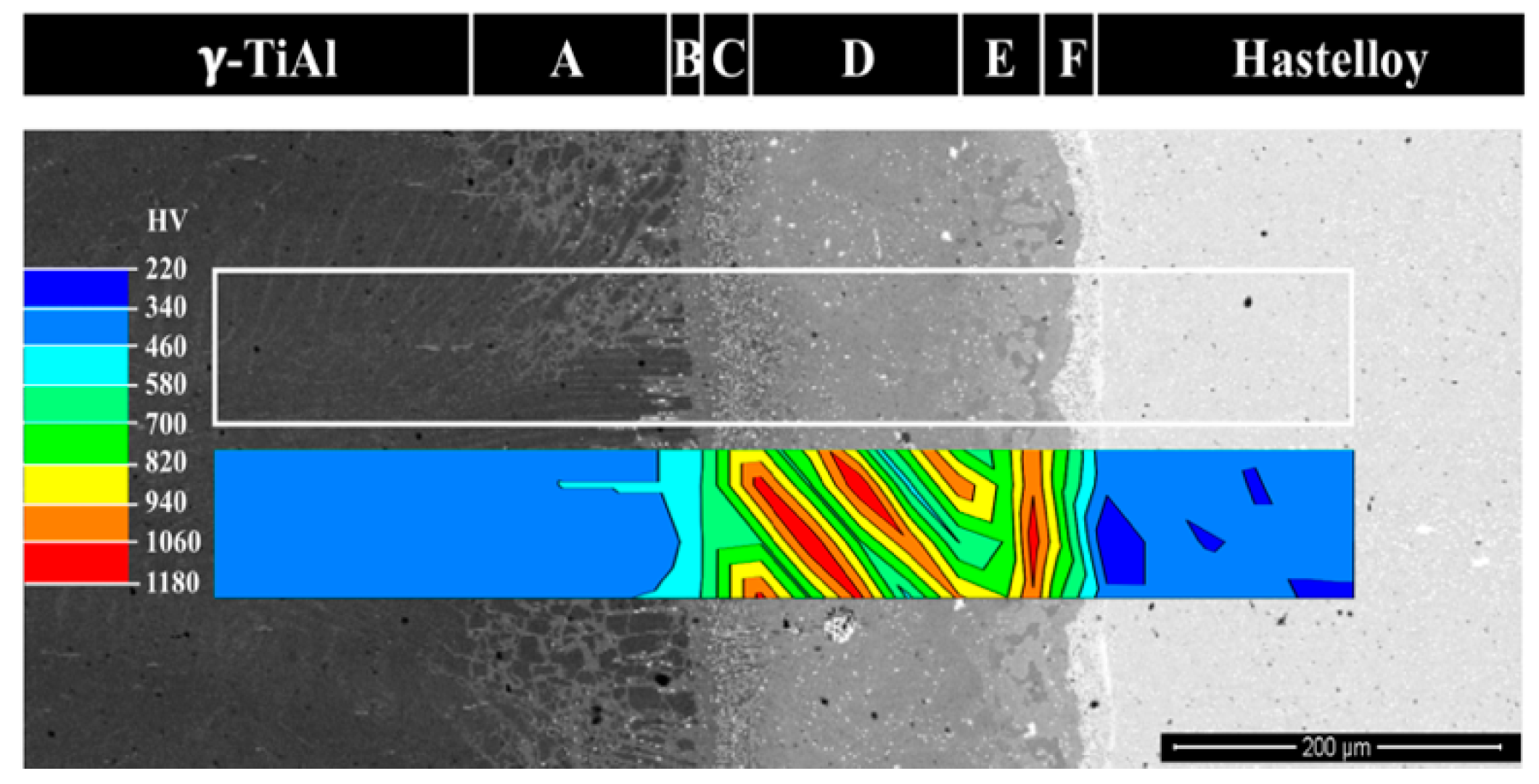
Figure 9 shows the hardness distribution map of a selected area of a BEI of the interface of joints that are produced at 980 °C. Table 2 presents the average hardness values of each layer. It is important to note that some areas may overlap each other within a short distance, thus affecting not only the standard deviation values, but also the average values presented.
The hardness distribution map shows that the interface presents the highest hardness values and may exhibit significant variations in some of the regions/layers, particularly in those located at the center of the interface (Layers C, D, and E). These features result from the high diffusion of elements that constitute Hastelloy, especially Ni, which will promote an extensive formation of hard phases, such as Ni-rich intermetallics. Indeed, the higher hardness values seem to be always associated with zones where Ti2Ni and TiNi2Al may have formed. Nevertheless, it is clear from the results obtained in this investigation that segregation of coarse and brittle particles towards a specific zone of the interface or extensive formation of soft phases was avoided, contrary to what is reported in other studies. For instance, the brazing of TiAl alloys using Ti-based fillers [10,22] was reported to promote the formation of detrimental coarse particles of hard Ni-rich intermetallics that are located in a narrow central zone of the interfaces; in the present study, Ti-Ni intermetallics are dispersed across several layers with a combined width of around 250 µm, and they are always mixed with other phases. In other studies, the use of Ag [23] and Ag-based fillers [24] have been reported to produce large (Ag) segregation zones, which limit the operating temperature of joints to around 350/400 °C [12,13]; no extensive segregation of Ag was detected in the present investigation. Thus, the use of Ag-Cu sputtered coated Ti brazing filler that was developed in this study potentially avoids the need for eventual post-joining heat treatments in order to eliminate or to minimize the number of undesirable segregated phases formed at the brazed interface.
4. Conclusions
Joining of γ-TiAl alloy to Hastelloy using Ag-Cu sputtered coated Ti brazing filler at 980 °C, with a dwelling stage of 10 min, produces multilayered interfaces, which are apparently free from pores and cracks. The layered structure of the interface, starting from the γ-TiAl alloy side, can be described, in general terms, as γ-TiAl diffusion zone (Layer A)/γ-TiAl + α2-Ti3Al (Layer B)/α2-Ti3Al + TiNi2Al (Layer C) α2-Ti3Al + Ti2Ni (Layer D)/α-Ti + Ti2Ni (Layer E)/Ti-Ni + Cr-Ni-Mo rich phases (Layer F). In addition, a few small Ag-rich particles are detected in Layer A and thin Ti-Ag rich precipitates are also detected in Layers D and E. The use of the Ag-Cu sputtered coated Ti brazing filler avoids both extensive formation of (Ag) and segregation of coarse isolated Ti-Ni intermetallic particles. The interface is harder than either base materials, and it presents a tendency to increase from the periphery (300/500 HV0.01) towards the center (800/1100 HV0.01).
Author Contributions
S.S. conducted the brazing experiments, microstructural and mechanical characterizations; C.J.T. developed and produced the brazing filler; A.G. analyzed the data and discussed the results; all the authors participated in the design of the experiments and cooperated in writing the paper.
Funding
This work was financially supported by: Project-POCI-01-0145-FEDER-031579- funded by FEDER funds through COMPETE2020-Programa Operacional Competitividade e Internacionalização (POCI) and by national funds (PIDDAC) through FCT/MCTES.
Acknowledgments
The authors are grateful to CEMUP-Centro de Materiais da Universidade do Porto for expert assistance with SEM.
Conflicts of Interest
The authors declare no conflict of interest.
References
- Dimiduk, D.M. Gamma titanium aluminide alloys-an assessment within the competition of aerospace structural materials. Mater. Sci. Eng. A 1999, 263, 281–288. [Google Scholar] [CrossRef]
- Leyens, C.; Peters, M. Titanium and Titanium Alloys: Fundamentals and Applications; WILEY-VCH Verlag GmbH & Co. KGaA: Weinheim, Germany, 2003; pp. 89–145. ISBN 9783527305346. [Google Scholar]
- Bewlay, B.P.; Weimer, M.; Kelly, T.; Suzuki, A.; Subramanian, P.R. The science, technology and implementation of TiAl alloys in commercial aircraft engines. MRS Symp. Proc. 2013, 1516, 49–58. [Google Scholar] [CrossRef]
- Dai, J.; Zhu, J.; Chem, C.; Weng, F. High temperature oxidation behavior and research status of modifications on improving high temperature oxidation resistance of titanium alloys and titanium aluminides: A review. J. Alloys Compd. 2016, 685, 784–798. [Google Scholar] [CrossRef]
- Bewlay, B.P.; Nag, S.; Suzuki, A.; Weimer, M.J. TiAl alloys in commercial aircraft engines. Mater. High Temp. 2016, 33, 549–559. [Google Scholar] [CrossRef]
- Tomashchuk, I.; Sallamand, P. Metallurgical strategies for the joining of titanium alloys with steels. Adv. Eng. Mater. 2018, 20. [Google Scholar] [CrossRef]
- Simões, S.; Viana, F.; Ramos, A.S.; Vieira, M.T.; Vieira, M.F. TEM and HRTEM characterization of TiAl diffusion bonds using Ni/Al nanolayers. Microsc. Microanal. 2015, 21, 132–139. [Google Scholar] [CrossRef] [PubMed]
- Simões, S.; Ramos, A.S.; Viana, F.; Vieira, M.T.; Vieira, M.F. Joining of TiAl to steel by diffusion bonding with Ni/Ti reactive multilayers. Metals 2016, 6, 96. [Google Scholar] [CrossRef]
- Cao, J.; Qi, J.; Song, X.; Feng, J. Welding and joining of titanium aluminides. Materials 2014, 7, 4930–4962. [Google Scholar] [CrossRef] [PubMed]
- Guedes, A.; Pinto, A.M.P.; Vieira, M.F.; Viana, F. Joining Ti-47Al-2Cr-2Nb with a Ti/(Cu,Ni)/Ti clad-laminated braze alloy. J. Mater. Sci. 2003, 38, 2409–2414. [Google Scholar] [CrossRef] [Green Version]
- Rozanski, M.; Winiowski, A. Diffusion vacuum brazing of TiAl47 casting alloy based on TiAl (γ) intermetallic compound using Ag-Cu-Ti braze alloy. Kov. Mater. 2014, 52, 225–230. [Google Scholar] [CrossRef]
- He, Y.; Zheng, W.; Yang, J.; Zhu, D.; Yang, X.; Gao, Z. An analysis of high-temperature microstructural stability and mechanical performance of the Hastelloy N-Hastelloy N Superalloy joint bonded with pure Ti. Mater. Des. 2018, 144, 72–85. [Google Scholar] [CrossRef]
- Hardesty, R.; Jensen, M.; Grant, L. High Temperature Be Panel Development; NASA Contract Report 181777; NASA: Hampton, VA, USA, May 1989. [Google Scholar]
- Guedes, A.; Mollaoglu, H.; Viana, F.; Pinto, A.M.P.; Vieira, M.F. Brazing Ti-47Al-2Cr-2Nb to Inconel 718 with different filler alloys: Microstructural characterization of the interfaces. In Proceedings of the International Conference on Advances in Welding Science and Technology for Construction, Energy and Transportation, Istanbul, Turkey, 11–17 July 2010. [Google Scholar]
- Xu, Q.; Chaturvedi, M.C.; Richards, N.L.; Goel, N. Diffusion brazing of a Ti-45Al-2Nb-2Mn+0.8vol.%TiB~2 XD alloy. In Proceedings of the Second International Symposium, Structural Intermetallics, Champion, PA, USA, 21 September 1997; p. 323. [Google Scholar]
- Guedes, A.; Pinto, A.M.P.; Vieira, M.F.; Viana, F. Assessing the influence of heat treatments on -TiAl joints. Mater. Sci. Forum 2006, 514–516, 1333–1337. [Google Scholar] [CrossRef]
- Wang, Y.; Xia, Y.H.; Yang, Z.W.; Wang, D.P. Interfacial microstructure and mechanical properties of TC4/Ti3SiC2 contact-reactive brazed joints using a Cu interlayer. Ceram. Int. 2018. [Google Scholar] [CrossRef]
- Simões, S.; Soares, A.; Tavares, C.J.; Guedes, A. Joining of TiAl alloy using novel Ag-Cu sputtered coated Ti brazing filler. Microsc. Microanal. 2018. under review. [Google Scholar]
- Gupta, R.K.; Pant, B. 4-Titanium aluminides. In Intermetallic Matrix Composites; Mitra, R., Ed.; Woodhead Publishing: Cambridge, UK, 2018; pp. 71–93. ISBN 9780857093462. [Google Scholar]
- Villars, P.; Prince, A.; Okamoto, H. Handbook of Ternary Alloy Phase Diagrams; ASM International: Almere, The Netherland, 1995; ISBN 978-0-87170-525-9. [Google Scholar]
- Povoden-Karadeniz, E.; Cirstea, D.C.; Lang, P.; Wojcik, T.; Kozeschnik, E. Thermodynamics of Ti-Ni shape memory alloys. Calphad 2013, 41, 128–139. [Google Scholar] [CrossRef]
- Si, X.Q.; Zhao, H.Y.; Cao, J.; Song., X.G.; Tang, D.Y.; Feng, J.C. Brazing high Nb containing TiAl alloy using Ti–28Ni eutectic brazing alloy: Interfacial microstructure and joining properties. Mater. Sci. Eng. A 2015, 636, 522–528. [Google Scholar] [CrossRef]
- Shiue, R.K.; Wu, S.K.; Chen, S.Y. Infrared brazing of TiAl intermetallic using pure silver. Intermetallics 2004, 12, 929–936. [Google Scholar] [CrossRef]
- Liu, H.; Jicai, F. Vacuum brazing TiAl-based alloy to 40Cr steel using Ag-Cu-Zn filler metal. J. Mater. Sci. Lett. 2002, 21, 9–10. [Google Scholar] [CrossRef]
Figure 1.
Backscattered electron images (BEIs) of the as-sputtered brazing filler showing the Cu and Ag layers on Ti foil: (a) global view; and, (b) magnification of the zone indicated in (a).
Figure 1.
Backscattered electron images (BEIs) of the as-sputtered brazing filler showing the Cu and Ag layers on Ti foil: (a) global view; and, (b) magnification of the zone indicated in (a).

Figure 2.
Scheme of the matrix for the Vickers microhardness tests showing the indentation position (♦) across the joints.
Figure 2.
Scheme of the matrix for the Vickers microhardness tests showing the indentation position (♦) across the joints.

Figure 3.
Differential scanning calorimetry (DSC) curve for the Ag-Cu sputtered coated Ti brazing filler.
Figure 3.
Differential scanning calorimetry (DSC) curve for the Ag-Cu sputtered coated Ti brazing filler.

Figure 4.
Optical microscopy (OM) images of the joint interfaces obtained at (a) 900 °C, (b) 950 °C, and (c) 980 °C.
Figure 4.
Optical microscopy (OM) images of the joint interfaces obtained at (a) 900 °C, (b) 950 °C, and (c) 980 °C.

Figure 5.
BEIs of γ-TiAl alloy/Hastelloy interface produced after joining at 980 °C.

Figure 6.
Ti-Al phase diagram, where the Ti:Al atomic ratios of A1 and A2 zones are plotted, adapted from [19], with permission of Elsevier, 2018.
Figure 6.
Ti-Al phase diagram, where the Ti:Al atomic ratios of A1 and A2 zones are plotted, adapted from [19], with permission of Elsevier, 2018.

Figure 7.
Isothermal section at 750 °C of the Al-Ni-Ti [20] ternary phase diagram, where the EDS chemical compositions of B1, C1, D1, and D2 zones are plotted.
Figure 7.
Isothermal section at 750 °C of the Al-Ni-Ti [20] ternary phase diagram, where the EDS chemical compositions of B1, C1, D1, and D2 zones are plotted.

Figure 8.
Ti-Ni phase diagram, where the invariant reactions on the Ti-rich zone are highlighted, adapted from [21], with permission of Elsevier, 2013.
Figure 8.
Ti-Ni phase diagram, where the invariant reactions on the Ti-rich zone are highlighted, adapted from [21], with permission of Elsevier, 2013.

Figure 9.
BEI and hardness distribution map of the interface produced at 980 °C.


Table 1.
Energy dispersive X-ray spectroscopy (EDS) chemical composition (at.%) of typical zones detected in γ-TiAl alloy/Hastelloy joints produced at 980 °C.
Table 1.
Energy dispersive X-ray spectroscopy (EDS) chemical composition (at.%) of typical zones detected in γ-TiAl alloy/Hastelloy joints produced at 980 °C.
| Zones | Ti | Al | Nb | Ag | Cu | Ni | Cr | Fe | Mo | W | Possible Main Phase(s) |
|---|---|---|---|---|---|---|---|---|---|---|---|
| A1 | 46.0 | 49.1 | 4.9 | - | - | - | - | - | - | - | γ-TiAl |
| A2 | 45.3 | 45.2 | 5.5 | 3.0 | 1.0 | - | - | - | - | - | γ-TiAl |
| B1 | 62.4 | 19.1 | 3.2 | 2.5 | 2.3 | 7.2 | 2.6 | 1.1 | - | - | α2-Ti3Al |
| C1 | 50.2 | 19.8 | 4.1 | 1.2 | 3.9 | 18.3 | 2.5 | - | - | - | α2-Ti3Al + TiNi2Al |
| D1 | 60.4 | 7.7 | - | - | 2.0 | 28.2 | 1.7 | - | - | - | Ti2Ni |
| D2 | 65 | 16.8 | 2.0 | 2.8 | 2.7 | 7.1 | 3.6 | - | - | - | α2-Ti3Al + Ti2Ni |
| D3 | 41.4 | 10.9 | 1.1 | 32.3 | 2.6 | 9.9 | 2.1 | - | - | - | n.i. 1 |
| E1 | 59.1 | 7.5 | - | - | 1.9 | 27.7 | 1.7 | 2.1 | - | - | Ti2Ni |
| E2 | 60.9 | 10.6 | - | 2.3 | 2.1 | 8.6 | 4.6 | 1.1 | 5.4 | 4.4 | α-Ti + Ti-rich intermetallic |
| E3 | 41.9 | 9.7 | - | 28.6 | 2.3 | 5.4 | 3.6 | 1.4 | 4.0 | 3.1 | n.i. 1 |
| F1 | 14.5 | - | - | - | - | 40.8 | 20.8 | 3.1 | 13.4 | 7.4 | n.i. 1 |
| F2 | 1.7 | - | - | - | - | 25.3 | 34.2 | 8.9 | 20.7 | 9.2 | Cr-Ni-Mo rich precipitates |
1 n.i.—not identified due to the regions having a high number of elements in significant amounts.
Table 2.
Average hardness values (HV0.01) of the different layers detected at the interface produced at 980 °C.
Table 2.
Average hardness values (HV0.01) of the different layers detected at the interface produced at 980 °C.
| Zones | Hardness (HV0.01) |
|---|---|
| γ-TiAl | 396 ± 15 |
| A | 391 ± 16 |
| B | 489 ± 14 |
| C | 768 ± 80 |
| D | 1002 ± 114 |
| E | 1030 ± 65 |
| F | 748 ± 75 |
| Hastelloy | 357 ± 16 |
© 2018 by the authors. Licensee MDPI, Basel, Switzerland. This article is an open access article distributed under the terms and conditions of the Creative Commons Attribution (CC BY) license (http://creativecommons.org/licenses/by/4.0/).
Share and Cite
MDPI and ACS Style
Simões, S.; Tavares, C.J.; Guedes, A. Joining of γ-TiAl Alloy to Ni-Based Superalloy Using Ag-Cu Sputtered Coated Ti Brazing Filler Foil. Metals 2018, 8, 723. https://doi.org/10.3390/met8090723
AMA Style
Simões S, Tavares CJ, Guedes A. Joining of γ-TiAl Alloy to Ni-Based Superalloy Using Ag-Cu Sputtered Coated Ti Brazing Filler Foil. Metals. 2018; 8(9):723. https://doi.org/10.3390/met8090723
Chicago/Turabian StyleSimões, Sónia, Carlos José Tavares, and Aníbal Guedes. 2018. "Joining of γ-TiAl Alloy to Ni-Based Superalloy Using Ag-Cu Sputtered Coated Ti Brazing Filler Foil" Metals 8, no. 9: 723. https://doi.org/10.3390/met8090723
Note that from the first issue of 2016, this journal uses article numbers instead of page numbers. See further details here.