Initiation of Surface Cracks on Beam Blank in the Mold during Continuous Casting

1
School of Metallurgical and Ecological Engineering, University of Science and Technology Beijing, Beijing 100083, China
2
North China University of Science and Technology, Tangshan 063210, Hebei, China
3
Hebei Engineering Research Center of High Quality Steel Continuous Casting, Tangshan 063009, Hebei, China
*
Author to whom correspondence should be addressed.
Metals 2018, 8(9), 712; https://doi.org/10.3390/met8090712
Submission received: 8 August 2018
/
Revised: 5 September 2018
/
Accepted: 9 September 2018
/
Published: 11 September 2018
(This article belongs to the Special Issue 5th UK-China Steel Research Forum)
Abstract
:Surface cracking seriously affects the quality of beam blanks, a relatively new blank in the continuous casting in China. In order to study the mechanism of the initiation and propagation of surface cracks, this study established a 2D micro-segmented model of the solidification process for a beam blank in the mold, with a user subroutine DFLUX written in Fortran. Using a contact algorithm, the stress in the shell of the beam was analyzed considering the mechanical properties of the material (Q235B), thermal stress, surface friction force and ferrostatic pressure. The results showed that at the center of the web, surface longitudinal cracks were most likely to initiate at a height of 180 mm from the meniscus; at the fillet, surface longitudinal cracks were most likely to initiate at a height of 200 mm from the meniscus. Moreover, the casting speed showed a greater effect on surface crack initiation than the pouring temperature did. This study reveals the cause of longitudinal crack initiation, and the most likely positions of cracks on the strand. Thus, it is instructive for controlling surface cracks in production.
1. Introduction
The main factors causing the occurrence of surface cracks in the shell of the beam blanks during continuous casting are the heterogeneous distributions of stress and temperature in the shell. Compared to a normal slab, as a near-net shape, the cross-section of the beam blank is more complex, and the stress and temperature distributions are more uneven. Figure 1 shows the cross-sectional shape and the cracks in an actual beam blank.
Research on crack formation in beam blanks has been performed worldwide. Kim et al. [1] established a 2D transient finite element method (FEM) coupled thermo-elastic-plastic model. It was used to simulate the thermodynamic behavior of the solidified shell of a cast beam blank, and analyze the formation of surface and internal cracks. Thomas et al. [2] simulated the temperature of the beam blank meniscus and analyzed the influence of the fillet shape on the fillet temperature by establishing a 2D steady state model. Lee et al. [3] used a numerical simulation to predict the appearance of surface cracks in the web and fillet areas, and internal cracks in the flange tip area. It was then proposed that the taper of the mold should be controlled to reduce the stress on the solidified shell.
Chen et al. [4] established a FEM coupled thermo-elastic-plastic model to compute the temperature and stress contours in the continuous casting of a steel beam blank and found that cracks were easily generated in the web and the flange tips. Chen et al. [5] developed a 2D transient state model to simulate the stress and temperature distribution on the beam blank surface, discovering that high heat flow was the critical factor in surface crack formation on the web. They proposed an optimum water-spraying intensity, according to metallurgical criteria, to suppress surface cracking.
Xu et al. [6] demonstrated that small-diameter water cooling channels could reduce the incidence of cracks. They successfully suppressed the formation of surface longitudinal cracks in the fillet.
Seok et al. [7] found that in order to reduce the longitudinal surface cracks of a beam blank, the C content of the steel should avoid the peritectic point of 0.12–0.13%, while the solute S and P concentrations should be low and the casting speed should not be too high.
Kelly et al. [8] also found that, when casting a steel billet with 0.1% C, the phase transformation of δ-Fe to γ-Fe could occur, which reduced the heat flux and induced longitudinal surface cracking.
The studies above are helpful for enhancing the quality of beam blanks formed by continuous casting. However, most of these studies have concentrated on adjusting the continuous-casting process parameters. As a relatively new type of casting blank in China, the quality of beam blank is far from sufficient. Deep theoretical investigations of the mechanisms of crack initiation and extension have not yet been performed.
In order to study crack initiation mechanisms on beam blank surfaces during molding, a 2D microsegment model was developed to analyze the distribution of temperature and stress using FEM in ABAQUS software (Version 6.12, Dassault Systèmes Simulia, Versailles, France). During the simulation, contact algorithms and restart techniques are used and the thermal stress, ferrostatic pressure, and friction are considered.
2. Methodology
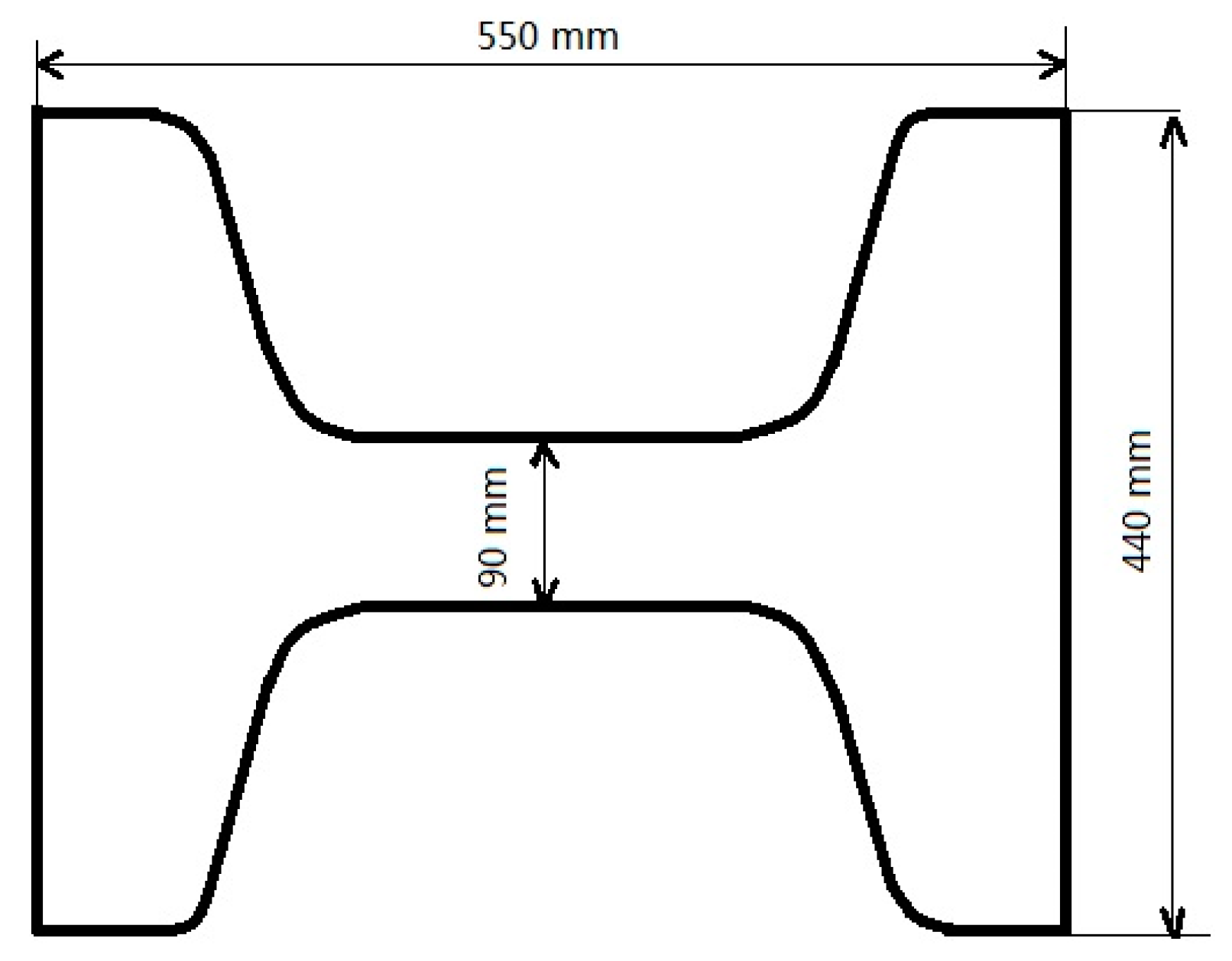
The cross-section of the modeled beam blank is 550 mm × 440 mm × 90 mm, as shown in Figure 2. Based on the specimen symmetry, only a quarter of the cross-section is simulated; the shape and elements of the model are shown in Figure 3. As shown in Figure 3, in order to guarantee the calculation accuracy and reduce the calculation time, different grid densities for different positions in the cross section of the beam blank are needed. The calculated thickness of the blank shell at the outlet of the mold is about 20 mm. Therefore, a relatively dense grid is set for the outer surface layer of 20 mm, and a rough grid is adopted for the inner region.
2.1. Assumptions
- The heat transfer between the blank shell and mold wall is expressed as equivalent heat transfer coefficient; the convective heat transfer coefficient in the mushy zones and liquid pool can be considered as three times and six times the thermal conductivity of the solid shell respectively [5].
- The air gap is filled with mold flux.
- The latent heat during solidification is considered using the method of equivalent heat capacity.
- The beam blank mold is a non-taper mold.
2.2. Heat-Transfer Equation
With the assumptions above, the solidification heat transfer of beam blank continuous casting becomes a 2D unsteady-state heat transfer problem with an internal heat source. The model adopts the following heat conduction equations according to El-Bealy et al. [11] and Janik et al. [12].
The heat transfer control equations are expressed as follows:
where is the density of liquid steel (kg/m3), is the thermal conductivity (W/m·°C), is the internal heat-intensity (W/m3), is the heat capacity (J/kg·°C), is the time (s), and T, x, and y have their usual meanings of temperature and position coordinates, respectively.
The latent heat is produced during the liquid-to-solid phase transition and is expressed as follows:
where is the solid fraction. In this study, the latent heat is simplified with the equivalent specific heat (ceff) method. Then, Equation (1) can be rewritten as:
2.3. Thermal Stress Equations
The thermal stress in the casting beam blank process belongs to the problem of thermal elastoplastic. Therefore, the Von-Mises yield criterion and Prandtl-Reuss flow rule are adopted.
In the plastic deformation range [13]:
Here,
In elastic deformation range:
In the transition zone, the weighted elastoplastic matrix is used to replace the elastic matrix.
Here, is the elastoplastic matrix, is the elastic matrix, is the stress matrix, is the equivalent stress, T is the temperature, is the temperature difference, is thermal expansion coefficient matrix, is the total strain increment, H is the dependence of new yield stress on the total amount of equivalent plastic strain. is the slope of the reinforcement curve of .
2.4. Boundary Conditions
- The initial temperature of the strand is the temperature of liquid steel in the tundish.
- Axisymmetric boundary conditions are applied on the symmetry plane of the strand.
- The heat flux in the mold follows the formula proposed by Savage and Pritchart [14]:where is the heat flux (kW/m2), employs the empirical constant 2688 kW/m2 [4,5,15,16], and is obtained by the formula: [9], where is the time at which a transverse slice moves from the meniscus to the exit of the mold, is the internal surface area of the mold, and is the heat flow of the mold: , where is the cooling water consumption of the mold, is the density of water, is the specific heat of water, and is the temperature difference of cooling water from the inlet to the outlet of the mold.
2.5. Submodel DFLUX
A user subroutine DFLUX for heat flow is written with Fortran to calculate the heat transfer. The basic code is based on the Abaqus User Subroutines Reference Manual (6.12) for DFLUX (Dassault Systemes, 2012a) [19].
2.6. Contact Algorithm and Restart Technique
A contact algorithm and restart technique are used to analyze the stress in the shell. The contact algorithm can automatically judge the contact condition between the shell and meniscus. According to the contact force, the algorithm decides whether to use the friction coefficient between the mold and strand. To consider the effect of the stress on the subsequent stress, the restart technique is applied. The main code is written according to the Abaqus User Subroutines Reference Manual (6.12) for DLOAD (Dassault Systemes, 2012b) [20].
3. Temperature Field
This work adopted the actual operating parameter values used by the JinXi Iron & Steel Group. The mold effective length was 700 mm, the casting speed was 1.0 m/min, the broad-face water flow of the mold was 216 t/h and the narrow-face flow was 120 t/h, the pouring temperature was 1550 °C, and the steel grade was Q235B.
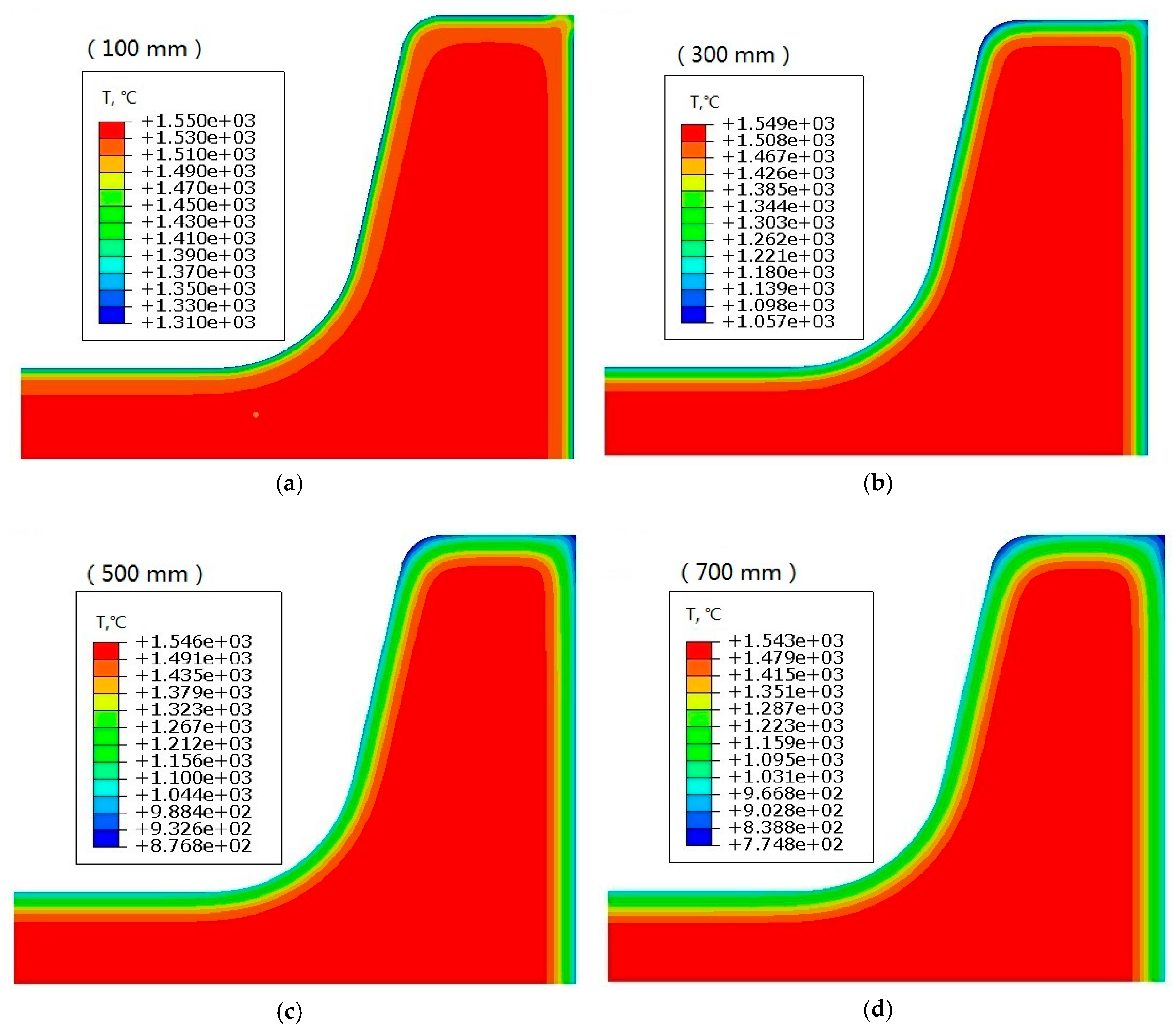
The temperature contours of the beam blank cross-section are displayed in Figure 4. Figure 4a–d depict the temperature contours at the distances of 100 mm, 300 mm, 500 mm, and 700 mm from the meniscus, respectively. The contours show that the surface temperature of the entire beam blank gradually decreases as the strand moves downwards; at the exit of the mold, the temperature distribution is uneven, with the lowest and highest temperatures occurring at the flange tip and fillet, respectively. The temperature distribution in other locations is relatively uniform.
The temperatures at several feature points are decreased as the strand moves downward, as shown in Figure 5. At the exit of the mold, the temperatures at the web center (A), fillet (B), flange slope center (C), internal corner of the flange (D), flange tip center (E) and narrow face center (F) are 980 °C, 1040 °C, 973 °C, 813 °C, 949 °C, 974 °C, respectively. The maximum temperature difference is 227 °C.
The simulation results in this study are basically the same as that of Chen et al. [5]; thus, the simulation results are credible and the model is reasonable.
4. Stress Field
The equivalent stress distribution contours of the shell during strand solidification are shown in Figure 6. At the initial stage of solidification (Figure 6a), the maximum equivalent stress occurs at the region of the web and flange tip, and the minimum occurs at the fillet. Moreover, the equivalent stress distribution is more uneven along the cross-section as the strand moves downward (Figure 6b–d), and the position of the maximum equivalent stress gradually moves inward from the surface. Throughout the solidification process in the mold, the equivalent stress at the corner of the flange tip remains high. At the exit of the mold, the stresses at the web center (A), fillet (B), flange slope center (C), flange internal corner (D), flange tip center (E), and narrow face center (F) are 17 MPa, 18 MPa, 12 MPa, 19.97 MPa, 15 MPa and 14 MPa, respectively.
4.1. Maximum Principal Stress (MAXPS)
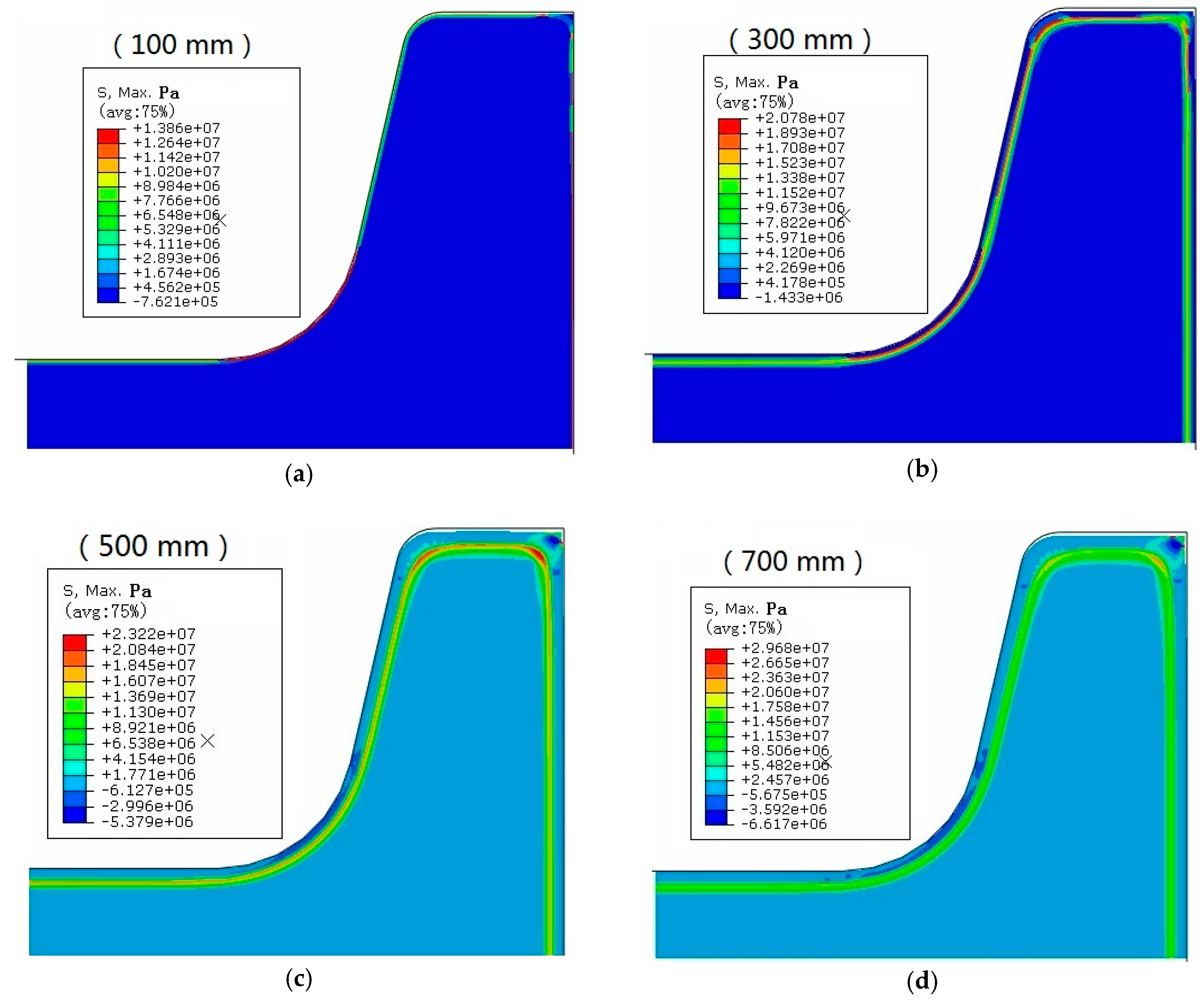
Figure 7 shows the distribution of maximum principal stress (MAXPS) of the transverse section of the casting strand at different heights in the mold. According to the model calculations, the principal stress at the fillet is the largest at the top of the mold (Figure 7a). As solidification continues, the position of the MAXPS moves inwards from the shell surface, and its distribution becomes gradually more uniform (Figure 7b–d).
4.2. Stress along X Direction
Figure 8 shows the stress contours along the wide-side X direction. The stress along the X direction is maximized at the web, fillet, and flange tip; the position of the maximum stress moves from the surface to the interior as solidification continues. Simultaneously, the stress along the X direction is reduced from the web to the flange. Furthermore, the temperature at the fillet is higher than that at the web and the flange. Therefore, longitudinal cracks caused by the stress along the X direction should appear at the web or at the fillet close to the web, while corner cracks are more likely to appear at the flange tip.
Figure 9 shows the stress along the X direction changing with distance from the meniscus at some typical points. It can be seen that during the solidification of the strand in the mold, the stress along the wide direction is tensile at first (positive sign denotes tensile stress), which then undergoes transition to compressive stress (negative sign denotes compression stress) and returns to the tensile stress state. Under compressive stress, cracks do not form and propagate. Thus, as shown in Figure 9, surface longitudinal cracks are more likely to form at the center of the web, fillet, and flange tip, owing to the high tensile stresses in the mold in these locations, especially during early solidification. By observing the location that has the maximum stress among the three tensile stresses, it is concluded that the heights at which surface longitudinal cracks form are 180 mm from the meniscus in the web center and flange tip center, and 200 mm from the meniscus in the fillet, at which the temperature of the strand is ~1200–1250 °C, as shown in Figure 5b. The stresses at the other positions along the width are relatively low in the mold, so cracks are unlikely to initiate and propagate.
4.3. Stress along Y Direction
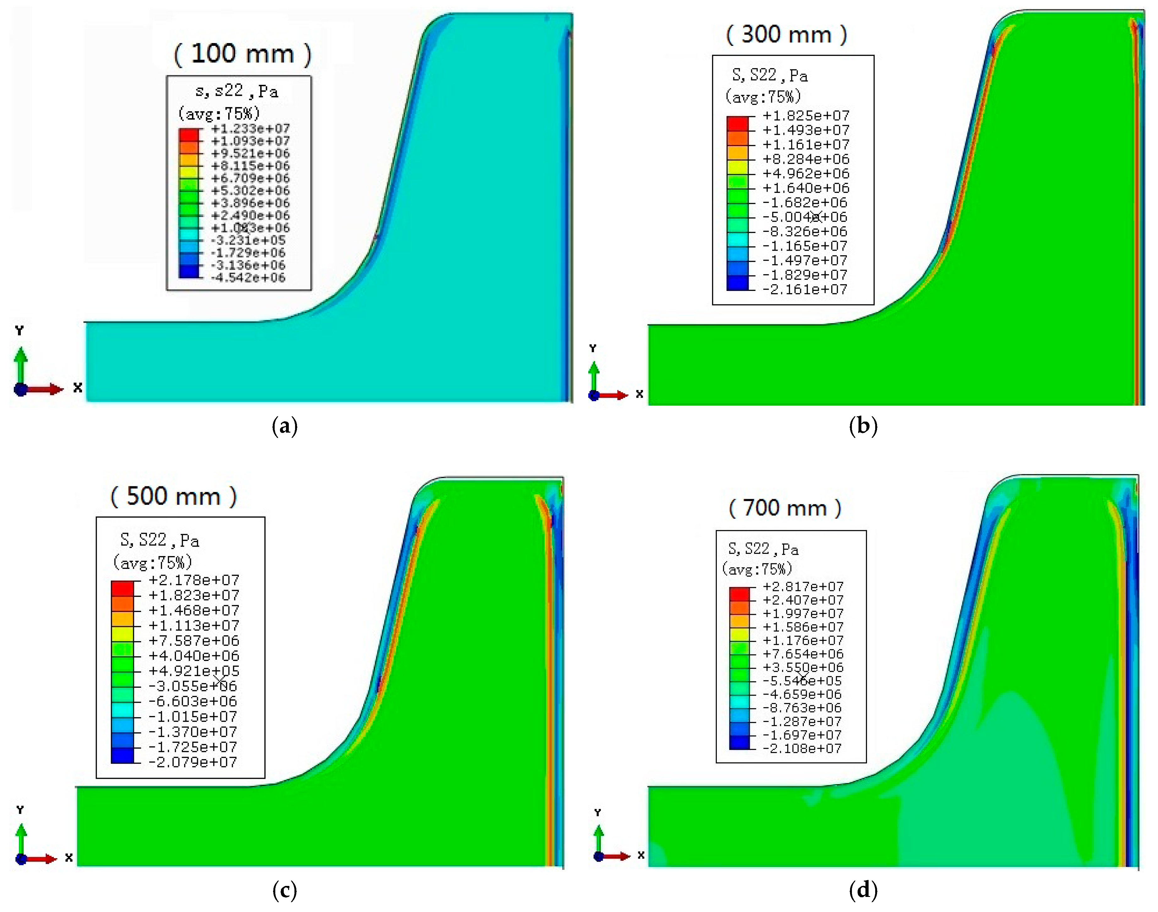
Stress contours along the narrow-side Y direction are shown in Figure 10. The pictures show that the stress along the Y direction is maximized at the narrow face and the inclined plane of the flange; the location of maximum stress moves from the surface to interior as solidification continues.
Figure 11 shows the stress along Y direction with distance from the meniscus at some typical points. It can be seen that, during the solidification of the strand in the mold, the stress along the narrow direction is tensile at first, which then undergoes transition to compressive stress, and returns to the tensile stress state. The values of the tensile stresses in the Y direction of the narrow-face center (F) and flange slope center (C) are larger than those in other locations throughout the mold, particularly in the upper part of the mold. Therefore, transversal surface cracks could appear more easily in the upper part of the narrow-face center and flange slope center.
Combining the stress curves with the X- and Y-stresses (Figure 9 and Figure 11), the center of the web and fillet have larger X-stress component values during solidification, with maximum values reaching 15.5 MPa and 12.9 MPa, respectively. The center of the narrow face has the largest Y-stress component value with the maximum of 8.98 MPa. This comparison shows that the maximum stress components appear in the upper part of the mold with X-stress components obviously being greater than Y-stress components, verifying the above conclusions that surface longitudinal cracks are more likely to occur on the wide side of the beam blank with crack initiation and propagation in the upper part of the mold. Combined with the temperature fields shown in Figure 5b and Figure 9 and considering production practice, the most vulnerable position for the formation of longitudinal surface cracks is the web center (180 mm from the meniscus), followed by the fillet (200 mm from the meniscus). The temperatures of these positions vary from 1200 °C to 1250 °C. These simulation results also agree with actual production observations.
5. Influences of Process Parameters on Solidification Process
5.1. Temperature Field at Different Casting Speeds
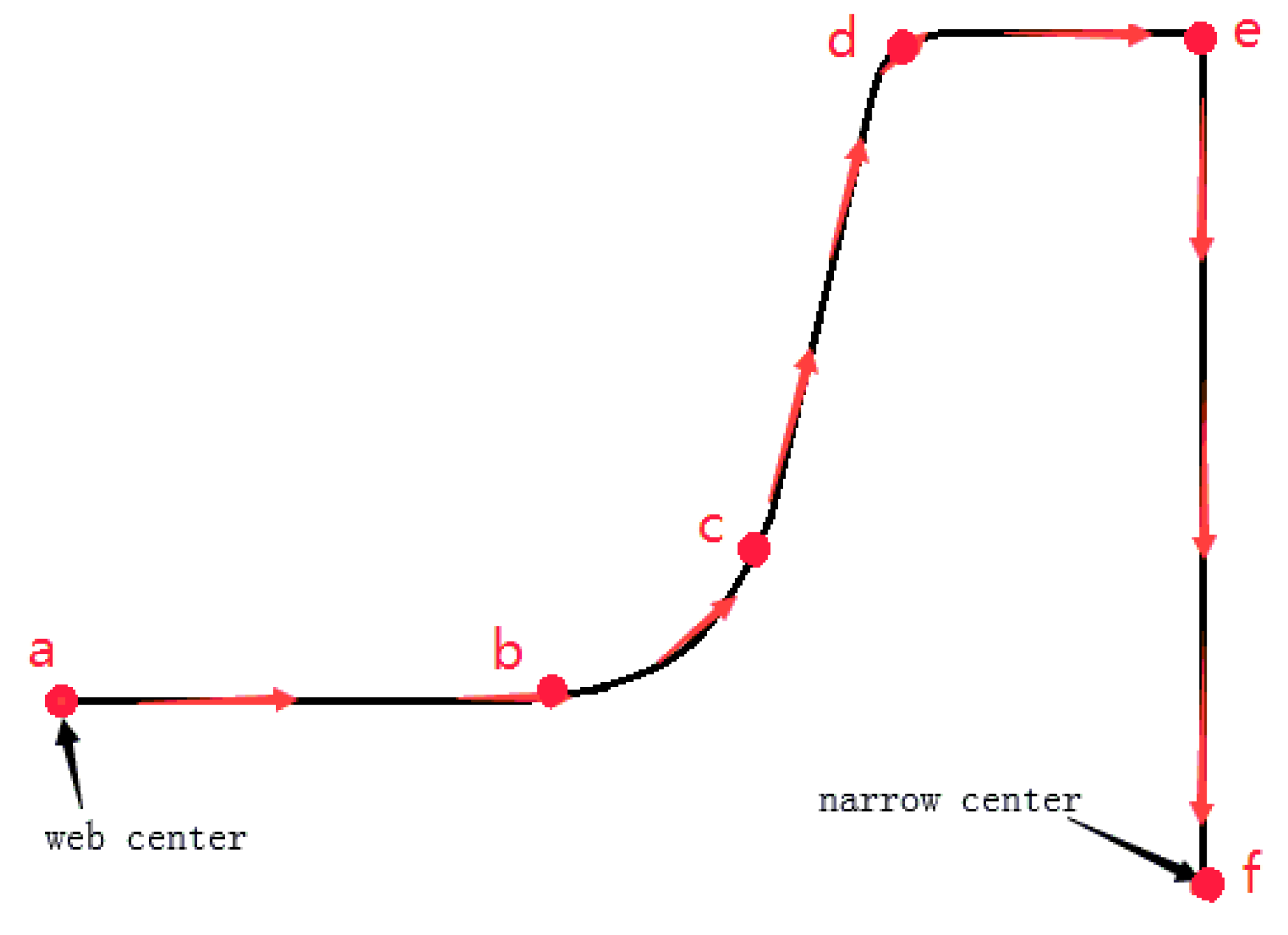
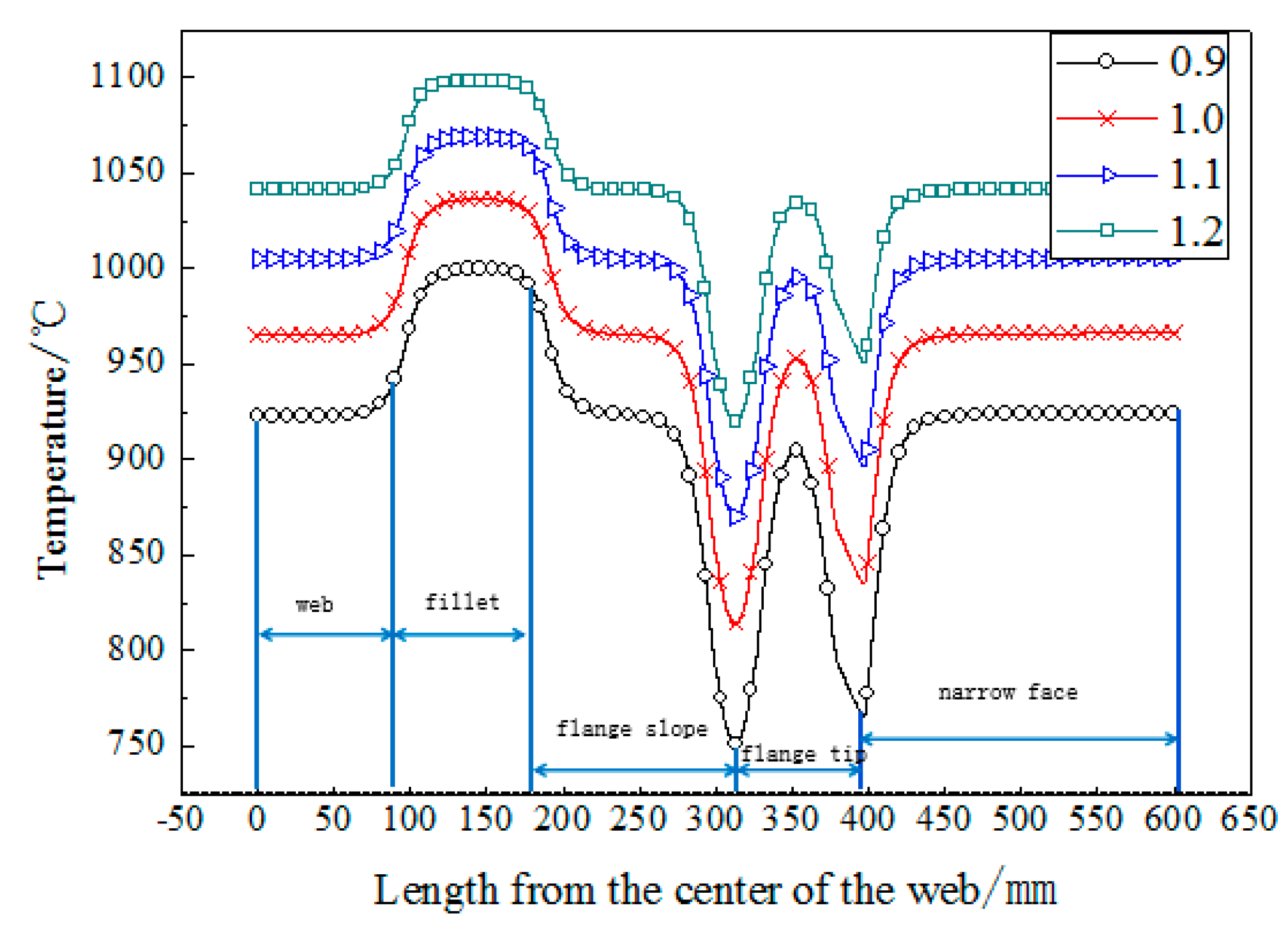
Figure 12 shows the peripheral diagram of a quarter of the beam blank. Figure 13 shows the temperature along the outer boundary at the exit of the mold, with casting speeds between 0.9 and 1.2 m/min. The length from the center of the web in Figure 13 refers to the length from the center of the web to the corresponding peripheral nodes along the outer boundary (as shown by the arrowhead in Figure 12). Combining Figure 12 and Figure 13, the marked length of web, fillet, flange slope, flange tip and narrow face in Figure 13 refers to the length of point a to point b, point b to point c, point c to point d, point d to point e, point e to point f along the outer boundary arrowhead in Figure 12, respectively. From the curves, the temperature at the exit of the mold increased with increasing casting speed. The temperature rose by 40 °C on average with each 0.1 m/min increase in the casting speed. It can also be seen from Figure 13 that the temperature of peripheral nodes of the web basically remained stable at any casting speed. The temperature of peripheral nodes in the transition zone from web to fillet kept rising, reaching the highest temperature at the center of the fillet and then remaining stable. The temperature of the nodes in the transition zone from the fillet to the flange slope gradually decreased, and the temperature at the slope was basically stable. However, the temperature dropped sharply to the lowest temperature during the transition from the flange slope to the inner corner of the flange tip. Due to the existence of the air gap at the flange tip, the temperature of the flange tip from the inner corner to the center of the flange tip rose significantly to the highest temperature at the flange tip, and then, from the tip center to the external corner, the temperature began to decline rapidly. Because the air gap is easy to be generated at a certain distance below the external corner of the narrow face, there is also a transition zone where the temperature rose sharply from the external corner to a certain distance below it in the narrow face. When there was no air gap on the narrow face, the temperature tended to stable.
5.2. Stress Field at Different Casting Speeds
From the initial analyses, the stress mainly caused surface cracks in the center of the web and the fillet. Therefore, the stresses at these two positions required additional investigation.
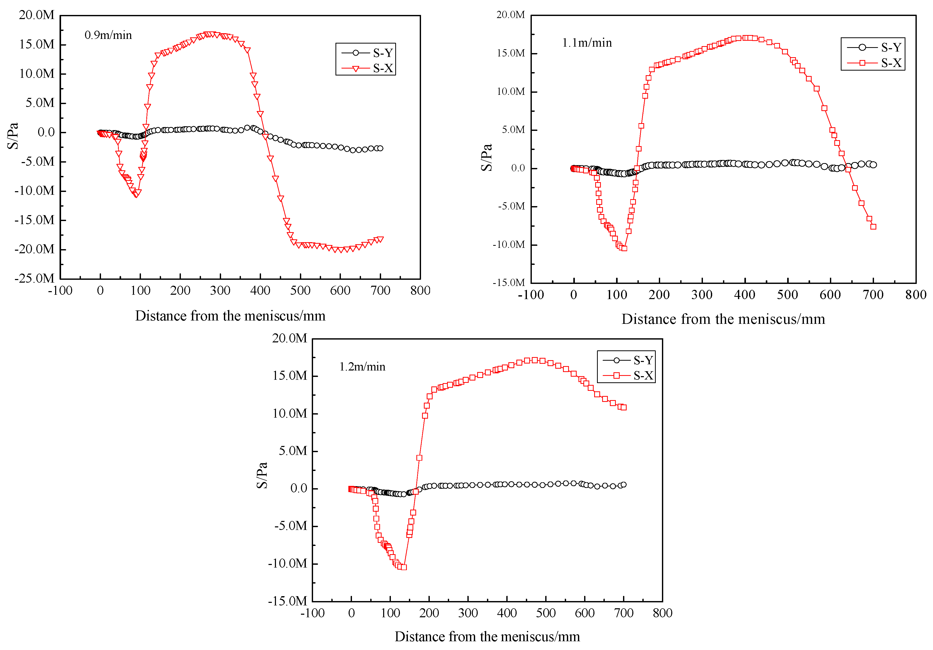
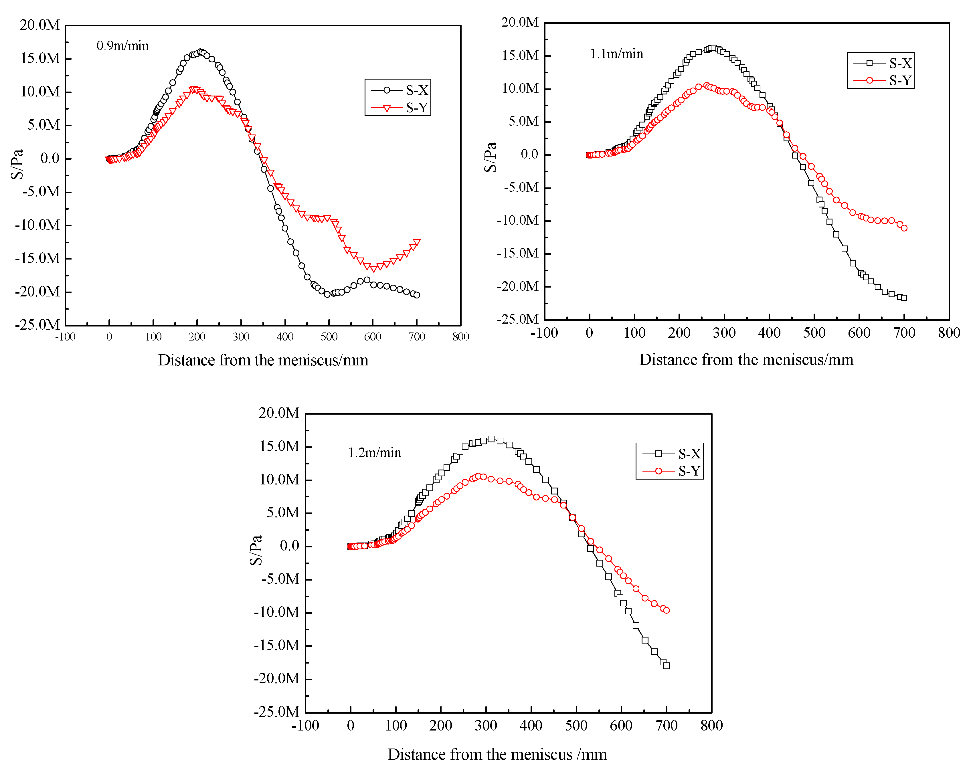
The stresses at the center of web and the fillet at different casting speeds are shown in Figure 14 and Figure 15, respectively.
With the increase of casting speed, the maximum stresses at the web and fillet did not change much. However, with the increase of casting speed, the position where the maximum stress appeared gradually moved towards the lower part of the mold.
The maximum stress and corresponding temperature values at web and fillet are listed in Table 1, which shows that the stress increases were very small at these positions (web or fillet), but the temperature increases were relatively large, thus deteriorating the mechanical properties and increasing the probability of crack occurrence.
5.3. Temperature Field at Different Pouring Temperatures
The temperatures along the outer boundary at the exit of the mold at different pouring temperatures are shown in Figure 16. For each 10 °C increase in pouring temperature, the temperature along the outer surface increased by an average value of 11 °C. The maximum temperature differences along the outer surface at the exit of the mold were 214 °C, 221 °C, 227 °C, and 230 °C at the pouring temperatures of 1530 °C, 1540 °C, 1550 °C, and 1560 °C, respectively. Therefore, as the pouring temperature rose, the temperature difference along the outer surface of the beam blank increased.
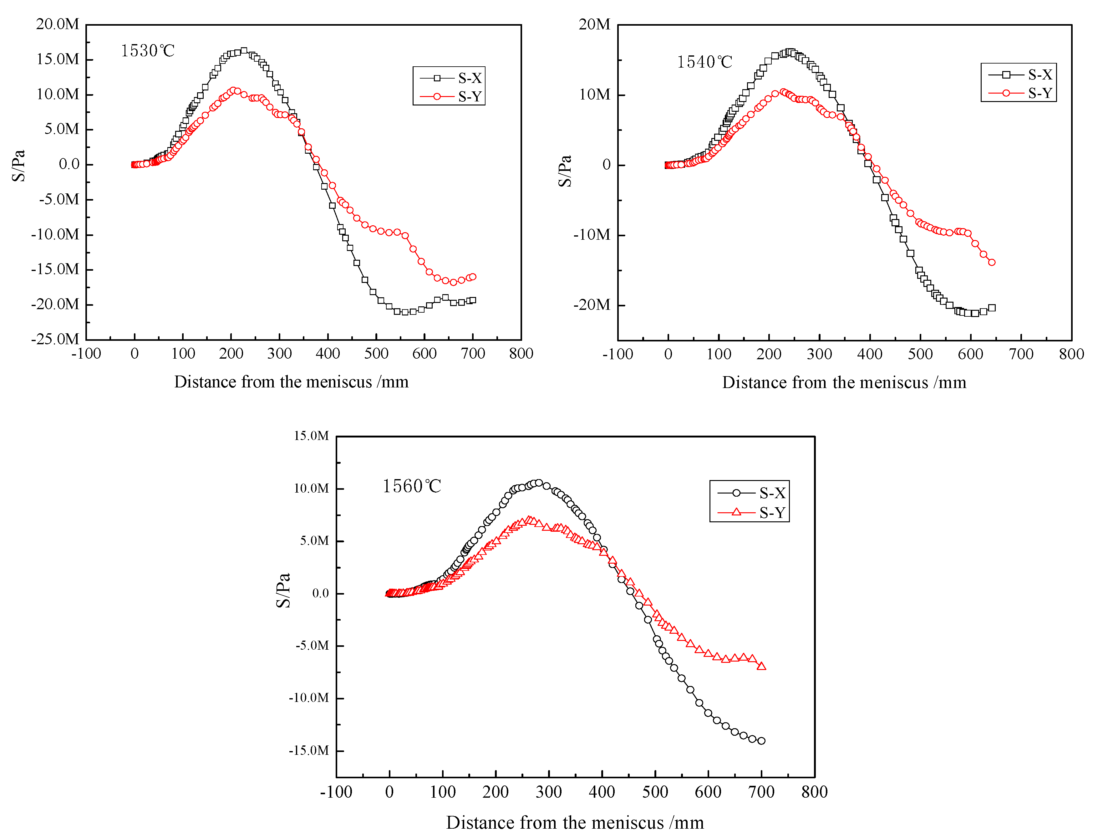
5.4. Stress Field at Different Pouring Temperatures
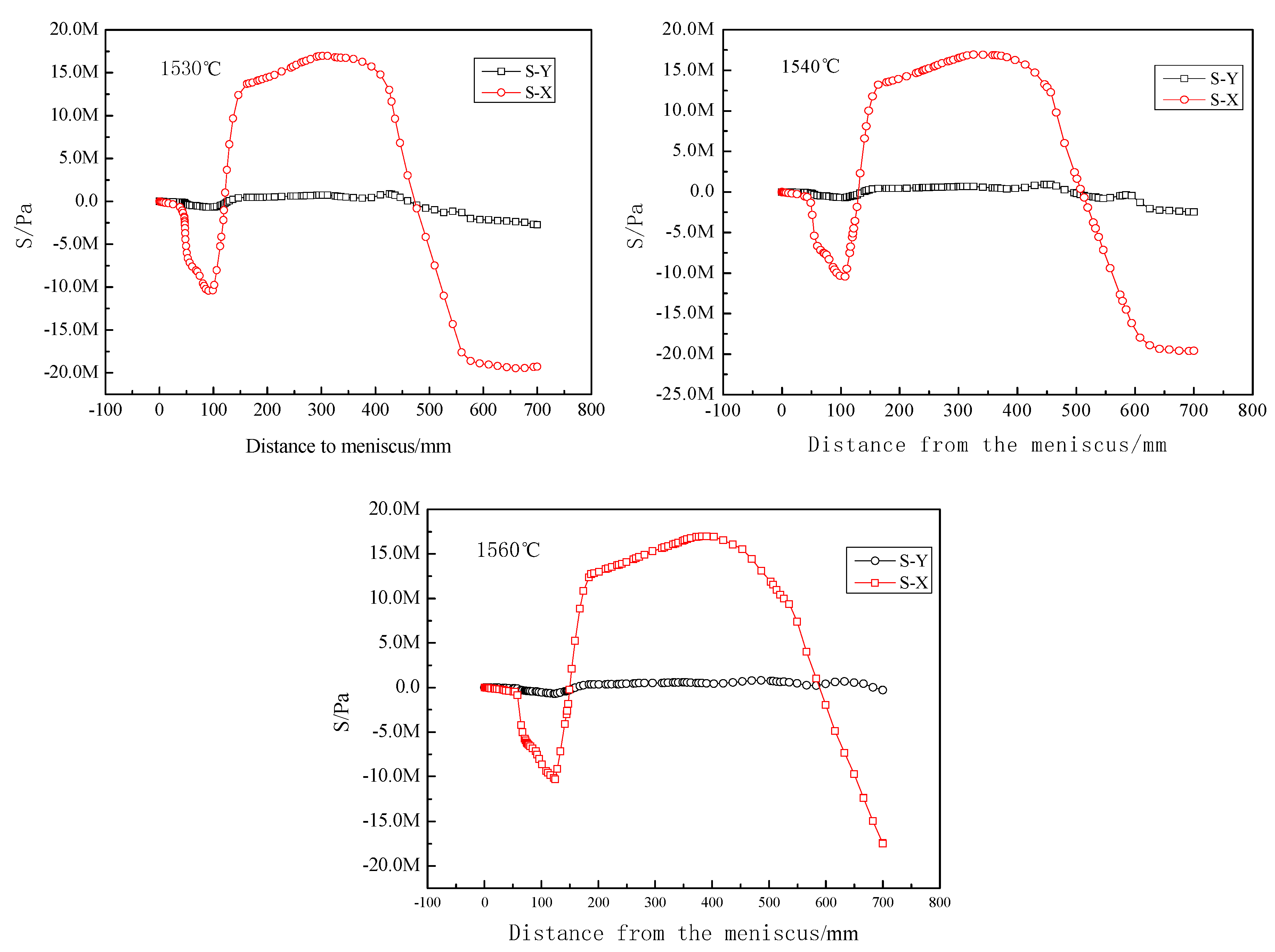
The stresses at the web and the fillet at different pouring temperatures are shown in Figure 17 and Figure 18. As the pouring temperature increased, the distance between the position of the maximum tensile stress and the meniscus of the mold was increased in the web and fillet. Therefore, crack initiation and propagation occurred at points lower in the mold.
Similar to the condition of the increasing casting speed, the increase in the amplitude of stress was very small at the web and the fillet, but the temperatures at these positions were increased significantly, thus degrading the mechanical properties. The temperature of the position of the maximum tensile stress was raised by 7 °C for each 10 °C increase in pouring temperature. This increase the probability of crack initiation.
After comparing the temperature and stress distributions at different casting speeds and pouring temperatures, the influence of casting speed was found to be much greater than that of the pouring temperature on the longitudinal surface cracking of the beam blank. Therefore, in order to reduce surface cracks, the casting speed must be controlled within 1.0 to 1.1 m/min.
6. Conclusions
In this study, a thermomechanical coupling model of the solidification process is established to simulate the temperature and stress fields for a beam blank in the mold. The conclusions are as follows:
- The temperature distribution is very inhomogeneous during solidification, with the highest temperature in the fillet and the lowest in the flange. The biggest temperature difference is 227 °C.
- The MAXPS is inhomogeneous along the transverse section of the beam blank. Early in the solidification process, the MAXPS is located on the fillet, and the temperature is also maximized there. The stress along the X direction is greater than that along the Y direction, especially in the web and fillet. This is the main cause for longitudinal crack initiation at the fillet and the web.
- In the present production conditions, the most vulnerable position for longitudinal surface crack formation is the web center (180 mm from the meniscus), followed by the fillet (200 mm from the meniscus). The temperatures of these positions are between 1200 °C and 1250 °C. These simulation results agree with observations from actual production.
- With increases in casting speed and pouring temperature respectively, the strand temperature increases relatively greatly when the tensile stress is at its maximum. This increases the probability of crack formation.
- The influence of casting speed on surface cracks is greater than that of the pouring temperature. Therefore, the casting speed should be strictly controlled to reduce the probability of surface cracks during production.
- This study reveals the mechanism of longitudinal crack initiation and their formation positions on the strand in the beam blank continuous casting, which permits greater control of surface cracks during production.
Author Contributions
W.C. and L.Z. conceived and designed the experiments and research ideas; G.Y., X.Y. and B.H. performed the experiments, the simulations, the early stage of the investigation and the data collection; W.C. and G.Y. analyzed the data; W.C. and L.Z. supervised the whole work; G.Y. wrote and revised the paper.
Funding
This research was funded by the National Natural Science Foundation of China (51574103 and 51574106).
Acknowledgments
The authors would like to thank the technical support of Hebei Engineering Research Center of High Quality Steel Continuous Casting.
Conflicts of Interest
The authors declare no conflicts of interest.
References
- Kim, K.; Han, H.N.; Yeo, T.; Lee, Y.; Oh, K.H.; Lee, D.N. Analysis of surface and internal cracks in continuously cast beam blank. Ironmak. Steelmak. 1997, 24, 249–256. [Google Scholar]
- Thomas, B.G.; Jiang, J.; Lorento, D. Optimization of Water Channel Design in Beam-Blank Mold. TMS. 2005, pp. 139–146. Available online: http://pdfs.semanticscholar.org/4cae/2fcc237136bd7653cf64cd6af6f1b13d5ee0.pdf (accessed on 9 January 2018).
- Lee, J.E.; Yeo, T.J.; Kyu Hwan, O.H.; Yoon, J.K.; Yoon, U.S. Prediction of cracks in continuously cast steel beam blank through fully coupled analysis of fluid flow, heat transfer, and deformation behavior of a solidifying shell. Metall. Mater. Trans. A 2000, 31, 225–237. [Google Scholar] [CrossRef]
- Chen, W.; Zhang, Y.Z.; Zhang, C.J.; Zhu, L.G.; Wang, B.X.; Lu, W.G.; Ma, J.H. Numerical simulation of the thermo-mechanical process for beam blank continuous casting. Acta Metall. Sin. (Engl. Lett.) 2007, 20, 241–250. [Google Scholar] [CrossRef]
- Chen, W.; Zhang, Y.Z.; Zhang, C.J.; Zhu, L.G.; Wang, S.M.; Wang, B.X.; Ma, J.H.; Lu, W.G. Thermomechanical analysis and optimisation for beam blank continuous casting. Ironmak. Steelmak. 2008, 35, 129–136. [Google Scholar] [CrossRef]
- Xu, H.L.; Wen, G.H.; Sun, W.; Wang, K.Z.; Yan, B.; Luo, W. Thermal behaviour of moulds with different water channels and their influence on quality in continuous casting of beam blanks. Ironmak. Steelmak. 2013, 37, 380–386. [Google Scholar] [CrossRef]
- Seok, Y.J.; Yoon, J.K. The effect of casting conditions on the formation of longitudinal surface crack in the beam blank caster. Met. Mater. Int. 2002, 8, 543. [Google Scholar] [CrossRef]
- Kelly, J.E.; Michalek, K.P.; O’Connor, T.G.; Thomas, B.G.; Dantzig, J.A. Initial development of thermal and stress fields in continuously cast steel billets. Metall. Trans. A 1988, 19, 2589–2602. [Google Scholar] [CrossRef]
- Yan, X.L. Principle and Numerical Simulation of Continuous Casting, 1st ed.; Hebei Science and Technology Press: Shijiazhuang, China, 2001; Chapter 1; p. 51. ISBN 7-5375-2475-0. [Google Scholar]
- Gao, Y.N. Theoretical Study on Heat Transfer Behavior in Slab Continuous Casting Mold; Northeastern University: Shenyang, China, 2009. [Google Scholar]
- El-Bealy, M.; Leskinen, N.; Fredriksson, H. Simulation of cooling conditions in secondary cooling zones in continuous casting process. Ironmak. Steelmak. 1995, 22, 246–255. [Google Scholar]
- Janik, M.; Dyja, H.; Berski, S.; Banaszek, G. Two-dimensional thermomechanical analysis of continuous casting process. J. Mater. Proc. Technol. 2004, 153–154, 578–582. [Google Scholar] [CrossRef]
- Liu, Q.; Zang, Y.; Qin, Q.; Zhao, J.Q. Analysis on temperature and thermal stress of H-beam during Cooling. Metall. Equip. 2008, 167, 17–20. [Google Scholar] [CrossRef]
- Savage, J.; Pritchard, W.H. The problem of rupture of the billet in the continuous casting of steel. J. Iron Steel Inst. 1954, 178, 269–277. [Google Scholar]
- Yang, J.W.; Du, Y.P.; Shi, R.; Cui, X.C. Fluid flow and solidification simulation in Beam blank continuous casting process with 3d coupled model. J. Iron Steel Res. Int. 2006, 13, 17–21. [Google Scholar] [CrossRef]
- Xu, H.L.; Wen, G.H.; Sun, W.; Wang, K.Z.; Yan, B. Analysis of thermal behavior for beam blank continuous casting mold. J. Iron Steel Res. Int. 2010, 17, 17–22. [Google Scholar] [CrossRef]
- Luo, W.; Yan, B.; Xiong, Y.X.; Wen, G.H.; Xu, H.L. Thermo-mechanical coupled numerical simulation of mould and strand in beam blank continuous casting. Mater. Sci. Technol. 2012, 20, 31–37. [Google Scholar]
- Chen, J.X. Manual of Continuous Casting Steel, 1st ed.; Metallurgical Industry Press: Beijing, China, 1991; Chapter 2; pp. 198–199. ISBN 7-5024-0887-8. [Google Scholar]
- Abaqus User Subroutines Reference Manual (6.12) for DFLUX. Dassault Systemes. 2012. Available online: http://abaqus.software.polimi.it/v6.12/books/sub/default.htm?startat=ch01s01asb03.html#sub-rtn-udflux (accessed on 9 January 2018).
- Abaqus User Subroutines Reference Manual (6.12) for DLOAD. Dassault Systemes. 2012. Available online: http://abaqus.software.polimi.it/v6.12/books/sub/default.htm?startat=ch01s01asb05.html#sub-xsl-dload (accessed on 9 January 2018).
Figure 1.
(a) Cross-section schematic of beam blank; (b) surface cracks on web and (c) fillet of actual beam blank.
Figure 1.
(a) Cross-section schematic of beam blank; (b) surface cracks on web and (c) fillet of actual beam blank.

Figure 2.
Schematic of the cross-section of the beam blank.

Figure 3.
(a) Whole elements; (b) elements near point A; (c) elements near point B; (d) elements near point C.
Figure 3.
(a) Whole elements; (b) elements near point A; (c) elements near point B; (d) elements near point C.
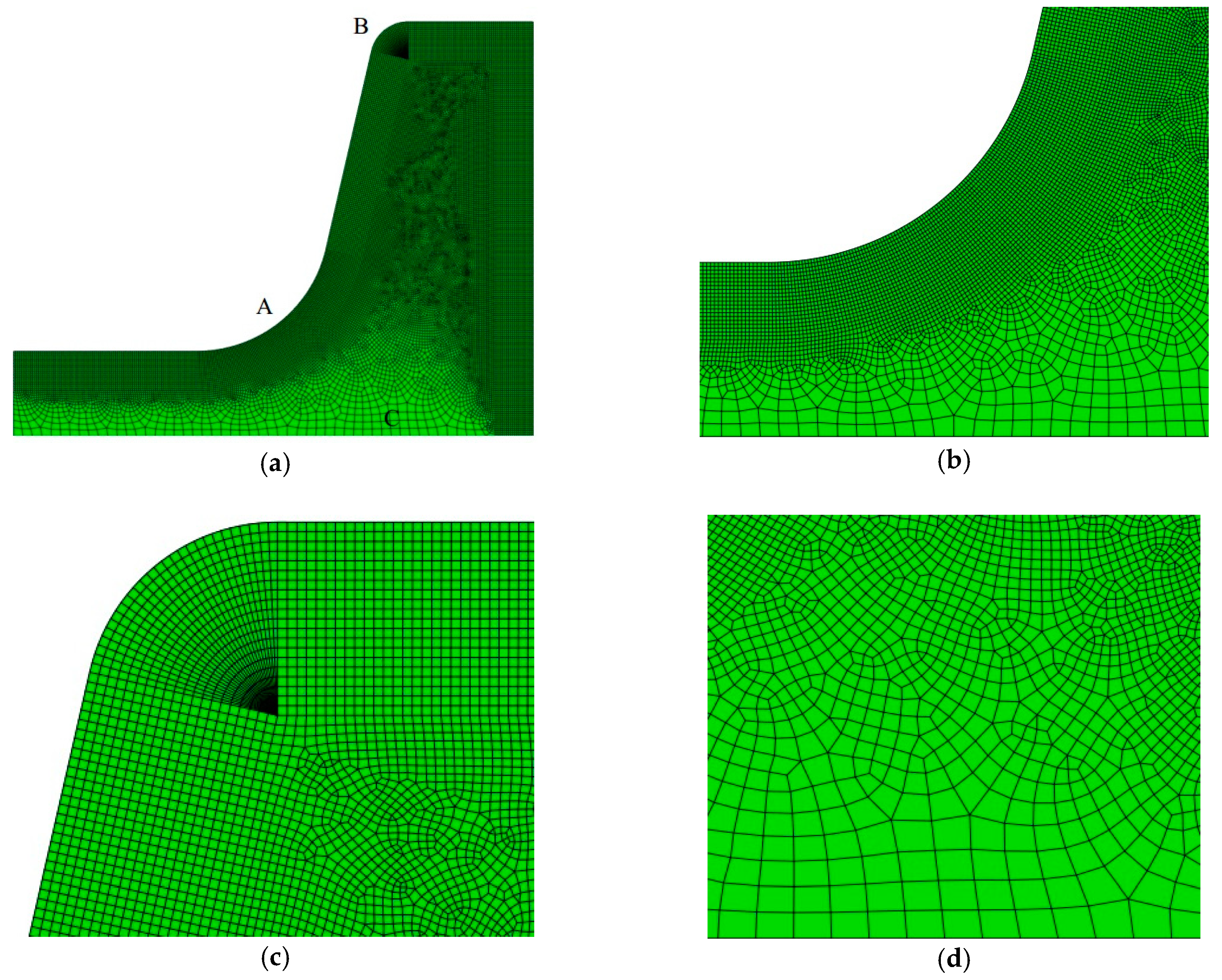
Figure 4.
Temperature contours at depths from the meniscus of (a) 100 mm; (b) 300 mm; (c) 500 mm; and (d) 700 mm in the mold.
Figure 4.
Temperature contours at depths from the meniscus of (a) 100 mm; (b) 300 mm; (c) 500 mm; and (d) 700 mm in the mold.

Figure 5.
(a) Position of the typical points and (b) Temperature curve of typical points at different distances from the meniscus.
Figure 5.
(a) Position of the typical points and (b) Temperature curve of typical points at different distances from the meniscus.
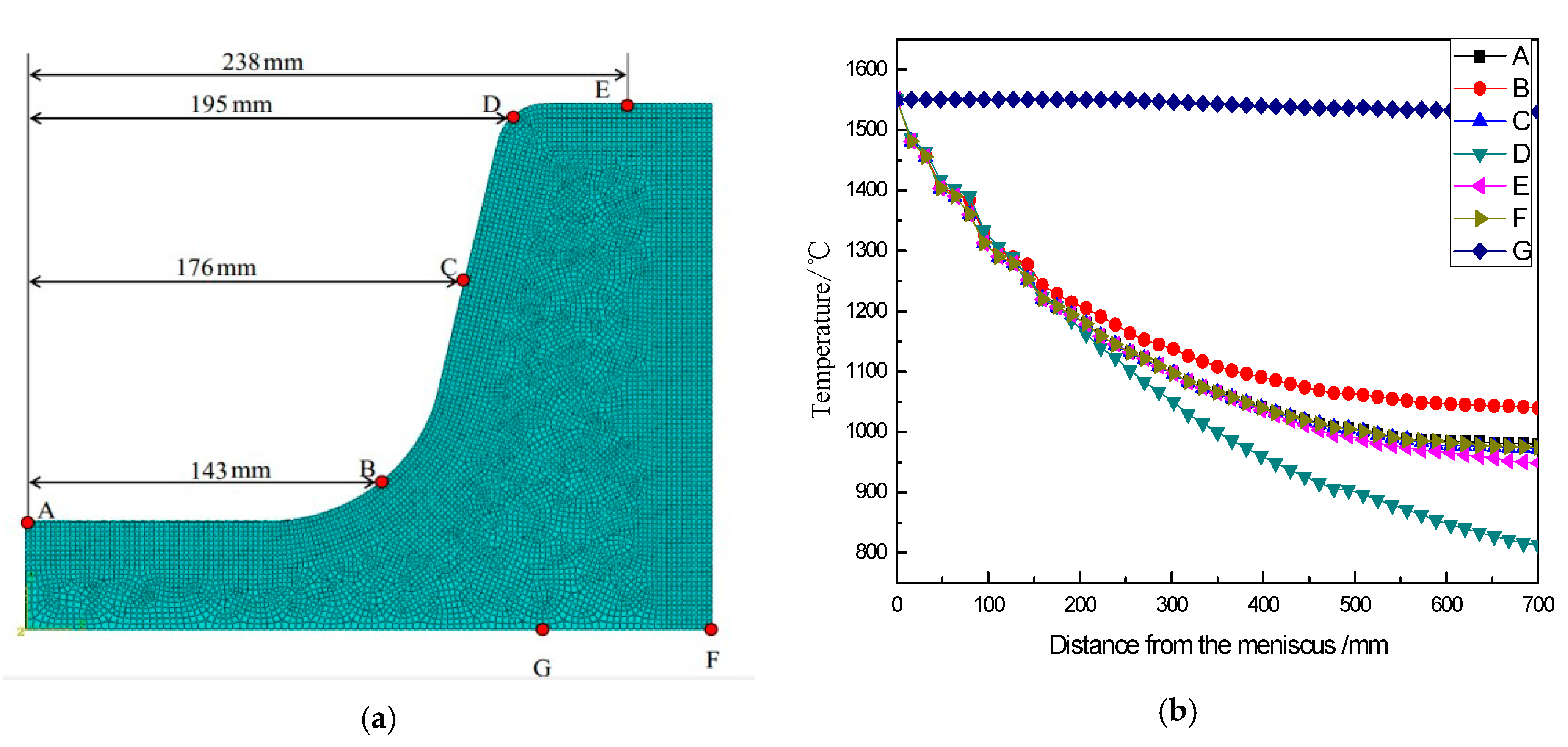
Figure 6.
Equivalent stress contours at depths from the meniscus of (a) 100 mm; (b) 300 mm; (c) 500 mm and (d) 700 mm in the mold.
Figure 6.
Equivalent stress contours at depths from the meniscus of (a) 100 mm; (b) 300 mm; (c) 500 mm and (d) 700 mm in the mold.

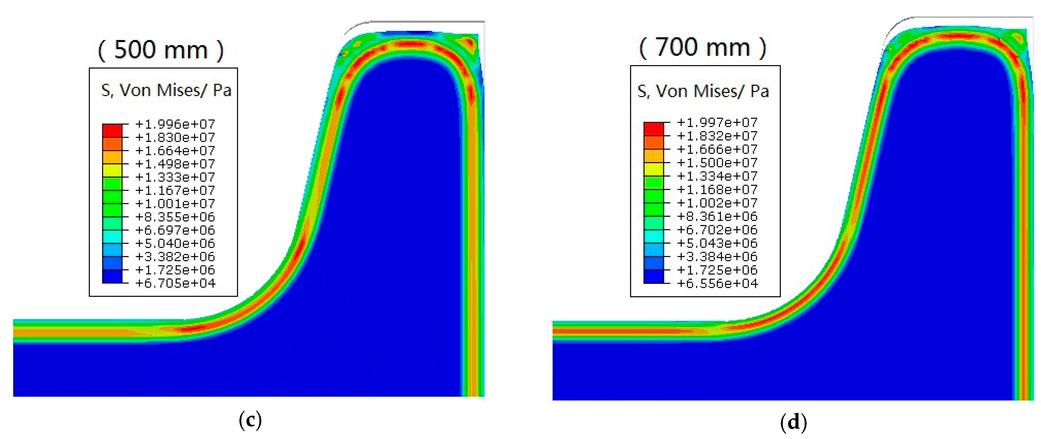
Figure 7.
MAXPS contours of cross-sections at depths from the meniscus of (a) 100 mm; (b) 300 mm; (c) 500 mm and (d) 700 mm in the mold.
Figure 7.
MAXPS contours of cross-sections at depths from the meniscus of (a) 100 mm; (b) 300 mm; (c) 500 mm and (d) 700 mm in the mold.

Figure 8.
Stress contours along the X direction at depths from the meniscus of (a) 100 mm; (b) 300 mm; (c) 500 mm and (d) 700 mm in the mold.
Figure 8.
Stress contours along the X direction at depths from the meniscus of (a) 100 mm; (b) 300 mm; (c) 500 mm and (d) 700 mm in the mold.
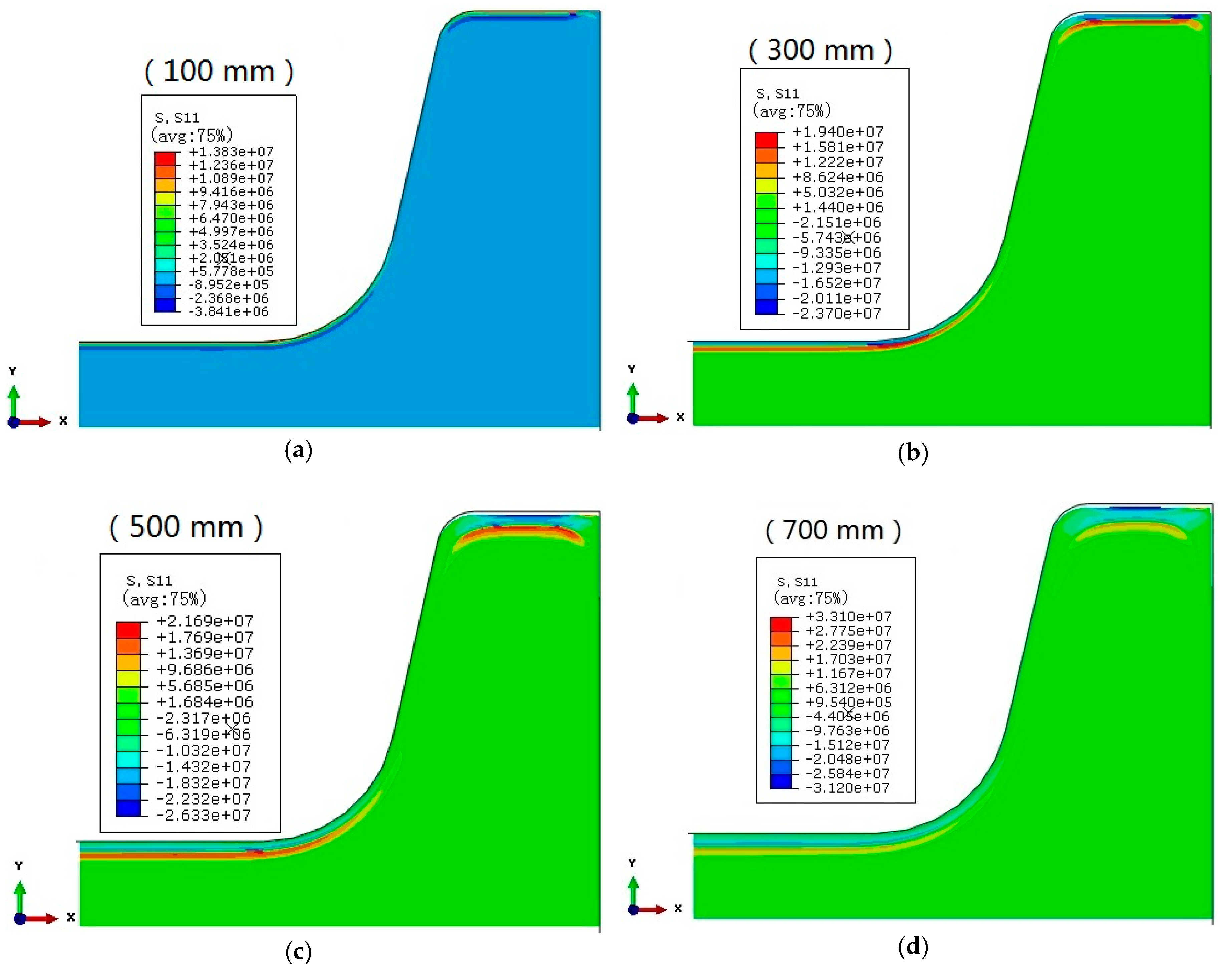
Figure 9.
Stress along X direction with distance at some typical points.
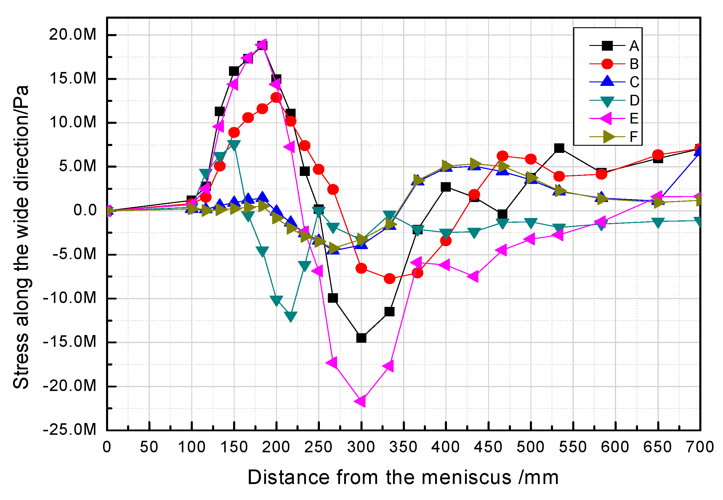
Figure 10.
Stress contours along Y direction at depths from the meniscus of (a) 100 mm; (b) 300 mm; (c) 500 mm and (d) 700 mm in the mold.
Figure 10.
Stress contours along Y direction at depths from the meniscus of (a) 100 mm; (b) 300 mm; (c) 500 mm and (d) 700 mm in the mold.

Figure 11.
Stress along Y direction with distance at some typical points.
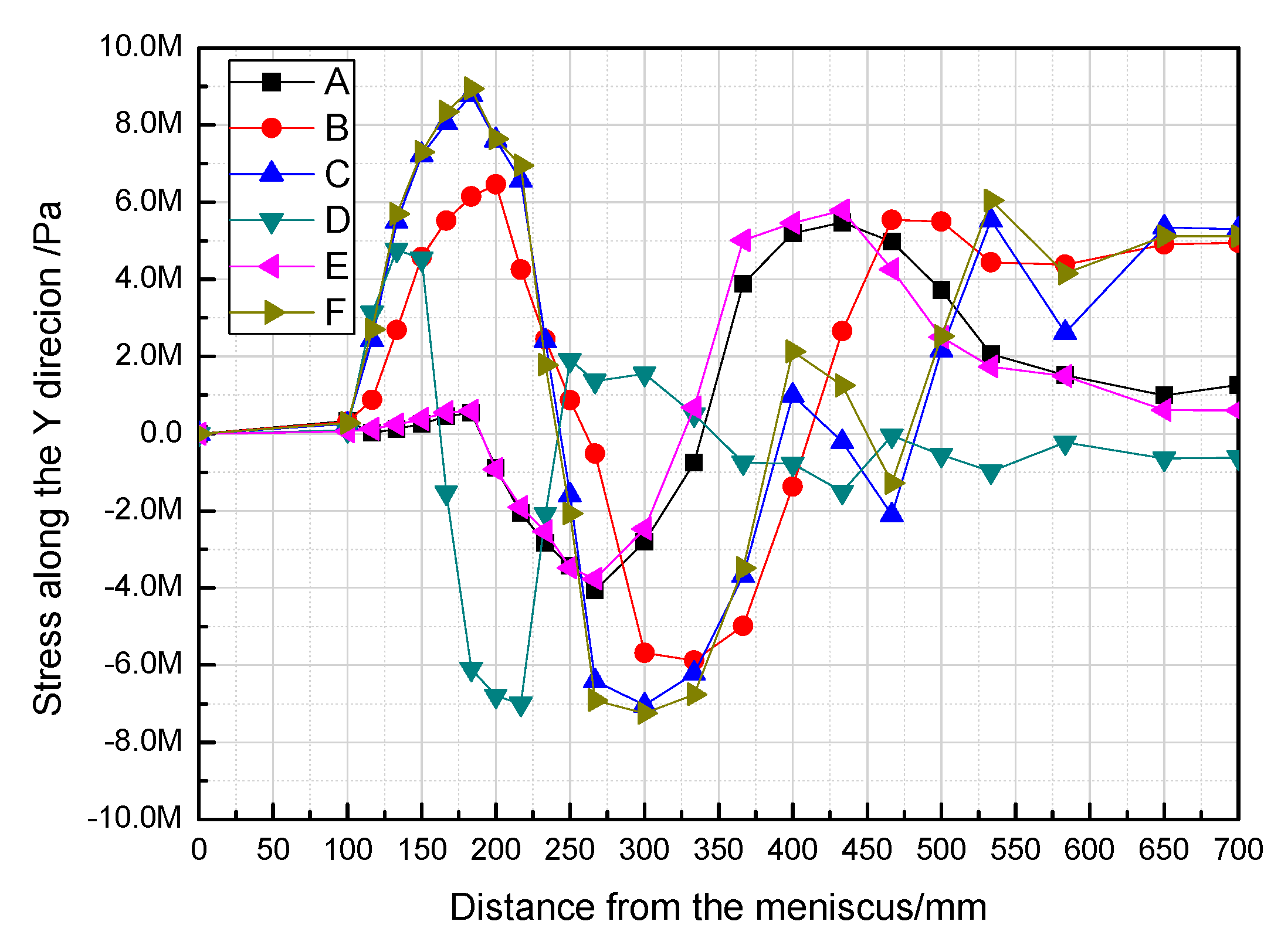
Figure 12.
Peripheral diagram of a quarter of the beam blank.

Figure 13.
Temperature along the outer boundary at the exit of the mold at different casting speeds.
Figure 13.
Temperature along the outer boundary at the exit of the mold at different casting speeds.

Figure 14.
Stress at the center of the web at different casting speeds.

Figure 15.
Stress at fillet at different casting speeds.

Figure 16.
Temperatures along the outer boundary at different pouring temperatures.
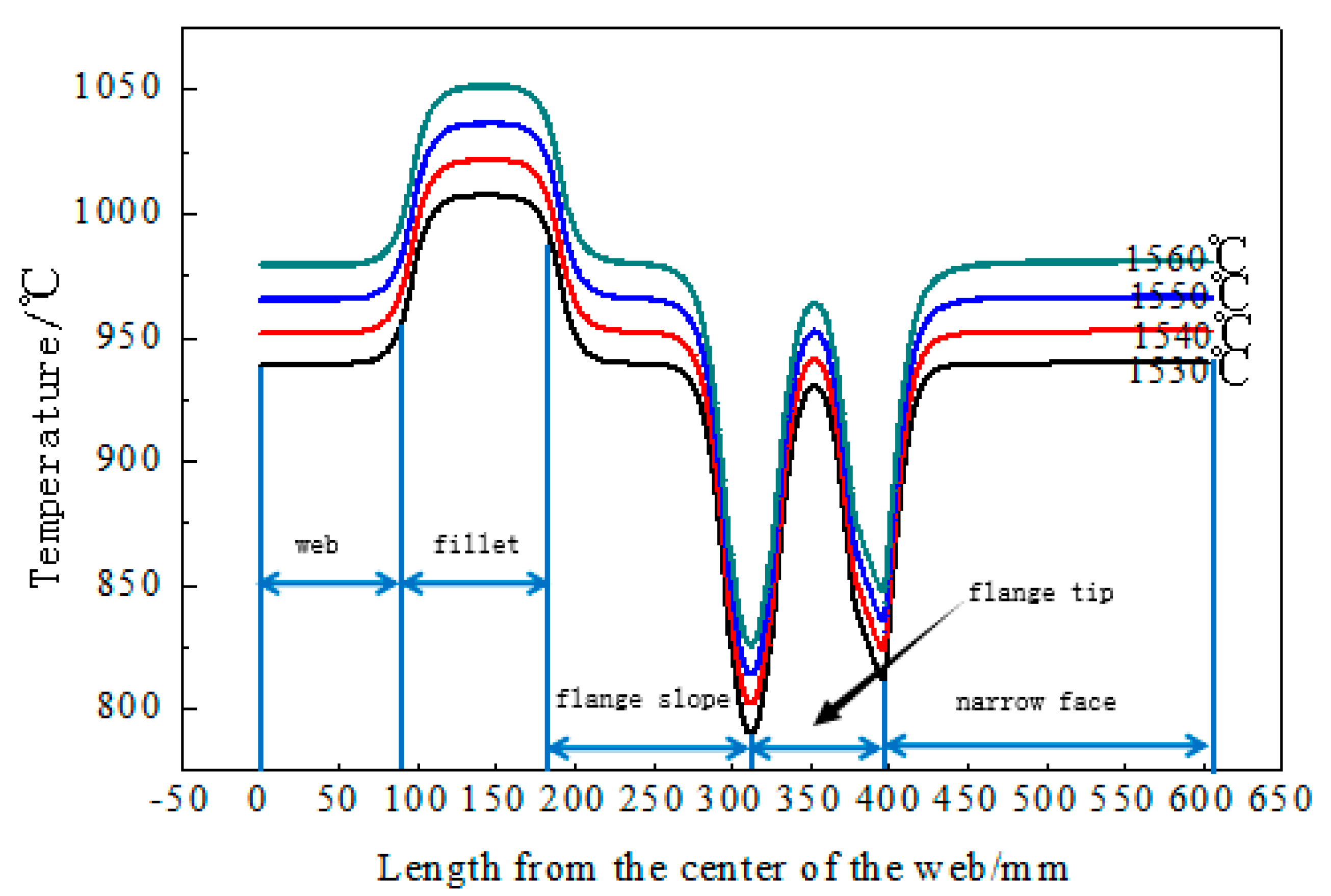
Figure 17.
Stresses on the web at different pouring temperatures.

Figure 18.
Stresses on the fillet at different pouring temperatures.


Table 1.
Maximum stress and its temperature at different casting speeds.
| Casting speed (m/min) | 0.9 | 1.0 | 1.1 | 1.2 |
| Maximum Stress on the Center of Web (MPa) | 16.9 | 17.0 | 17.0 | 17.1 |
| Temperature on the Center of Web (°C) | 1185 | 1200 | 1214 | 1218 |
| Maximum Stress on the Fillet (MPa) | 16.1 | 16.2 | 16.2 | 16.2 |
| Temperature on the Fillet (°C) | 1242 | 1250 | 1258 | 1261 |
© 2018 by the authors. Licensee MDPI, Basel, Switzerland. This article is an open access article distributed under the terms and conditions of the Creative Commons Attribution (CC BY) license (http://creativecommons.org/licenses/by/4.0/).
Share and Cite
MDPI and ACS Style
Yang, G.; Zhu, L.; Chen, W.; Yu, X.; He, B. Initiation of Surface Cracks on Beam Blank in the Mold during Continuous Casting. Metals 2018, 8, 712. https://doi.org/10.3390/met8090712
AMA Style
Yang G, Zhu L, Chen W, Yu X, He B. Initiation of Surface Cracks on Beam Blank in the Mold during Continuous Casting. Metals. 2018; 8(9):712. https://doi.org/10.3390/met8090712
Chicago/Turabian StyleYang, Gaiyan, Liguang Zhu, Wei Chen, Xingwang Yu, and Baomin He. 2018. "Initiation of Surface Cracks on Beam Blank in the Mold during Continuous Casting" Metals 8, no. 9: 712. https://doi.org/10.3390/met8090712
Note that from the first issue of 2016, this journal uses article numbers instead of page numbers. See further details here.