Study on Fracture-Split Performance of 36MnVS4 and Analysis of Fracture-Split Easily-Induced Defects


1
Roll Forging Research Institute, Jilin University, Changchun 130025, China
2
College of Materials Science and Engineering, Jilin University, Changchun 130025, China
*
Author to whom correspondence should be addressed.
Metals 2018, 8(9), 696; https://doi.org/10.3390/met8090696
Submission received: 17 August 2018
/
Revised: 1 September 2018
/
Accepted: 3 September 2018
/
Published: 5 September 2018
Abstract
:The material 36MnVS4 is the second generation of connecting rod fracture-split material. However, it generates more quality defects during the fracture-split process. To investigate the causes of defects that occurred, the material properties and fracture-split performance of the 36MnVS4 are researched and compared with C70S6. The fracture-split easily-induced defects are also analyzed. By finite element simulation and experimental analysis, the results show that the 36MnVS4 has lower carbon content and more ferrite, therefore the fracture surface of the 36MnVS4 connecting rod is more prone to tears and the plastic deformation range is greater. The fracture speed of the 36MnVS4 connecting rod is 20% lower than that of the C70S6 connecting rod. The slower fracture separation rate increases the possibility of defects generation. The crack initiation position of the 36MnVS4 connecting rod is random, scattered, and unstable, and the 36MnVS4 has higher gap sensitivity. Therefore, the 36MnVS4 connecting rod is more prone to produce quality defects in the fracture-split process. By changing the cross-section design, the outer edge of the joint surface is changed to arc-shaped, which can improve the fracture-split process of the 36MnVS4 connecting rod and reduce the processing defects.
1. Introduction
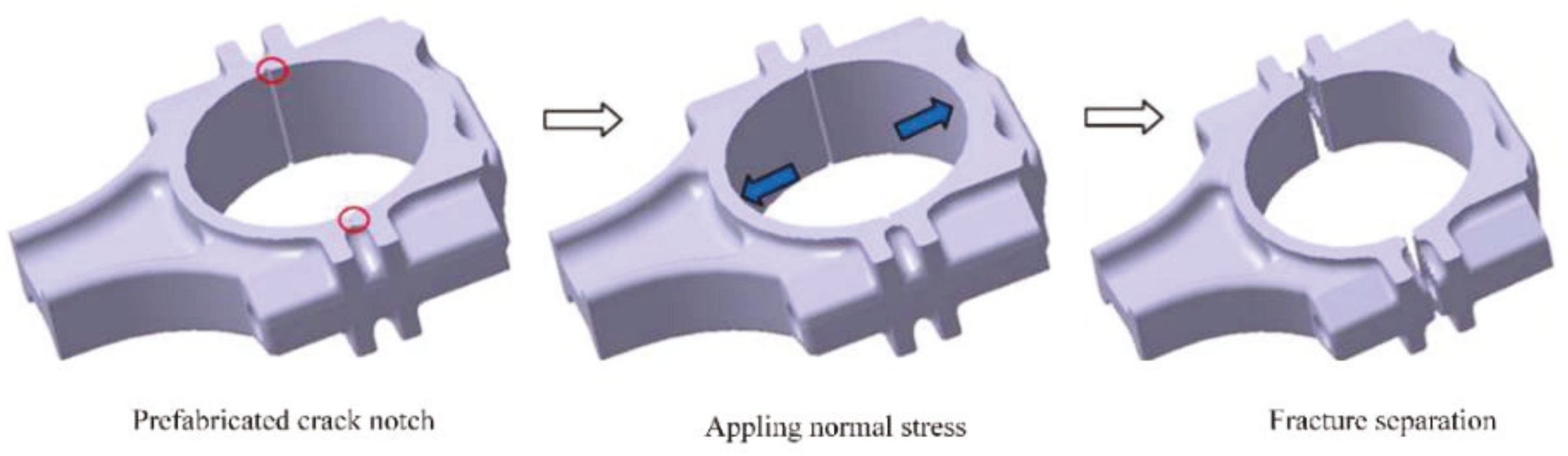
Fracture-split processing is the latest technology for the production of the connecting rods. The fracture-split process is shown in Figure 1. Firstly, the two fracture-split notches are symmetrically prefabricated on the joint surface. After that, a load perpendicular to the theoretical fracture surface are applied which causes stress concentration at the root of the fracture-split notch and promotes crack initiation. Finally, the crack initiation followed by unstable propagation, the connecting rod cover is separated from the rod body, and the quasi-brittle fracture surface with good meshing is obtained. The purpose of the pre-processed crack notch is to generate stress concentration and promote crack initiation, thereby realizing low stress quasi-brittle fracture of the connecting rod [1,2,3].
The fracture-split process of the connecting rod can obtain the staggered joint surface, which can realize the three-dimensional precise positioning of the connecting rod and the cover. Connecting rod fracture-split also can reduce the manufacturing procedure, increase the production efficiency, reduce the production cost, and greatly increase the load capacity [4,5,6]. Therefore, the fracture-split processing technology of connecting rods has been widely popularized and applied.
Connecting rod fracture-split is the process of crack initiation and propagation that involves many factors [7]. The fracture-split process is extremely fast and complex which is prone to generating quality defects such as crack bifurcation, break-out, fell-dregs, and steps. Research and control of the fracture-split defects are always a thorny problem to be solved.
At present, the most widely used fracture-split material is C70S6 [8]. Because of its relatively low strength and fatigue performance, it is difficult to meet the high-performance requirements of some high-power engines [9,10]. As cars develop toward being light weight and high quality, with low pollution, higher requirements are put forward for high explosiveness and low energy consumption of the engine. The various new materials are emerging. Medium carbon micro-alloyed non-tempered steel 36MnVS4 is a representative of the second generation of fracture-split connecting rod steel [11,12]. Using the production data of the C70S6 connecting rod to carry out fracture-split processed of the 36MnVS4 connecting rod generates many quality problems. In comparison, the C70S6 connecting rod has better fracture-split quality and fewer fracture-split defects. Exploring the fracture-split laws of the 36MnVS4 and the causes of defects produced is of great practical significance to improve the product qualification rate.
The mechanical properties of the material have an important influence on its fracture-split performance [13,14]. In order to explore the fracture-split performance of 36MnVS4, the microstructure is analyzed and the mechanical performance test is carried out. The materials have difference behavior of stress-strain curves in functions of temperature and strain rate [15,16,17]. The fracture-split process of the connecting rod is very rapid, and the time of fracture process is approximate 0.00001 s [18]. Therefore, strain rates need to be considered in the tensile test of the fracture-split materials. The fracture-split process is carried out at room temperature, therefore, the temperature has little effect on stress-strain curve of 36MnVS4 and C70S6. Next step, the influence of the strain rate on the tensile curve of the fracture-split material is necessary to conduct in-depth research.
The crack propagation of connecting rod fracture-split is a fast and unsteady process, and has a complex three-dimensional characteristic [19,20]. Therefore, it is difficult to capture the crack growth and obtain the relevant data by experiment [21]. With the promotion and maturity of commercial software, numerical simulation has become a very effective analysis method. Reasonable numerical simulation combined with corresponding tests have very important guiding significance for actual production, and can also save costs and time.
In the present work, the element content, microstructure, and mechanical properties of the 36MnVS4 and C70S6 materials are tested and analyzed. Based on the theory of fracture mechanics, the fracture-split process of the 36MnVS4 and C70S6 connecting rods are simulated by ANSYS/LS-DYNA software (14.5, ANSYS Corporation, Pittsburgh, PA, United States). The distribution laws of the main mechanical field of the whole fracture-split process are analyzed, and the fracture-split characteristics of the 36MnVS4 material are investigated. The defects produced in the process of the 36MnVS4 connecting rod fracture-split are evaluated and analyzed. The reason why the 36MnVS4 connecting rod is prone to generate defects is discussed, and the corresponding solutions are put forward.
2. Materials and Methods
2.1. Material Compositions and Microcosmic Characteristics
The main components of the fracture-split materials of the C70S6 and 36MnVS4 are shown in Table 1. As can be seen, C, S, and P are reduced in the 36MnVS4 compared to the C70S6. The reduction of C can significantly improve the cutting performance of the material. Mn, Si, Cr, Mo, and V can not only improve the hardenability of the material, but also form alloy carbides with carbon. The melting point, hardness, and stability of these carbides are high, which has a good dispersion-strengthening effect on the matrix, and refines the matrix grain [22]. The decrease of carbon content improves the plasticity of the 36MnVS4 which is not conducive to brittle fracture of materials.
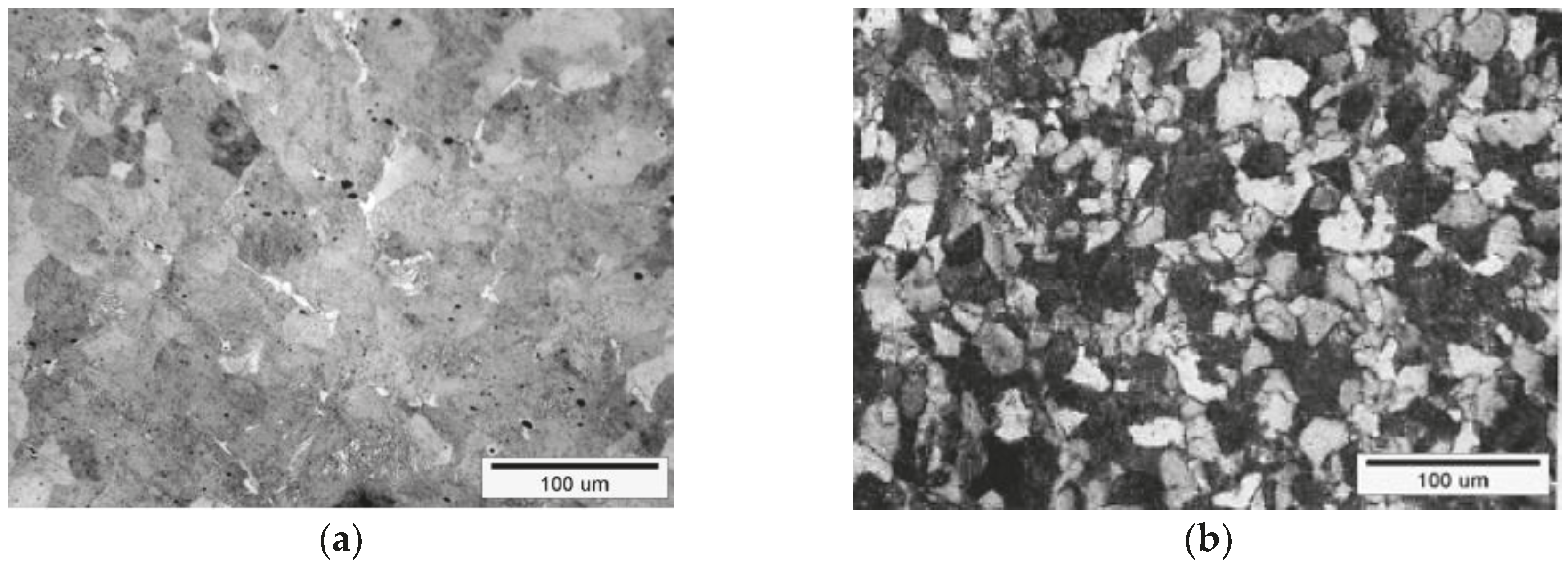
After hot forging and air cooling, samples of size 8 mm × 8 mm × 10 mm are selected from the 36MnVS4 and C70S6 connecting rods by wire cutting. Using alcohol as a solvent, the samples are cleaned by ultrasonic oscillation. Then, the samples are etched with nitric acid alcohol solution (Changchun chemical reagent Co. LTD., Changchun, China) and dried. Observation of the metallographic structure is conducted using an Olympus LEXT metallographic microscope (Olympus (China) Co. LTD., Beijing, China). The results are shown in Figure 2, which indicate that the C70S6 consists of a large number of fine pearlite and a small amount of intermittent network-like ferrite. The grain fineness number of the C70S6 is lower. The high-hardness lamellar cementite of the C70S6 reduces its machinability [23]. The 36MnVS4 is mainly composed of pearlite and ferrite. The grains are obviously refined compared to the C70S6. The bulk ferrite structure is precipitated along the grain boundary and the proportion of ferrite is larger. The ferrite is a relatively soft phase, which may make the fracture surface prone to tear defects in the process of fracture-splitting.
2.2. Mechanical Properties
The tensile test is conducted on the CSS-44100 microcomputer control electronic universal testing machine. CSS-44100 is a universal electronic universal testing machine which is manufactured by Jinan Ruima Machinery Equipment Co. Ltd in Jinan, China. The CSS-44100 is a large-scale precision testing instrument that can perform various performance tests on various materials such as stretching, compression, and bending. Standard samples are prepared according to the machining process of connecting rod forging and air cooling, and the basic dimensions of the sample are determined according to GB 6397-86. As a result, a short specimen with a diameter of 5 mm is selected. The connecting rod fracture-split is carried out at room temperature, therefore the tensile test of the C70S6 and 36MnVS4 is conducted at room temperature. For the tensile rate, only 0.1 mm/s is selected at the present stage [24]. The stress-strain curves under different strain rates will be further studied in the next step. Four specimens of C70S6 and 36MnVS4 are tested. The stress-strain curves obtained are shown in Figure 3, which will be imported into the finite element simulation software ANYSY (14.5, ANSYS Corporation, Pittsburgh, PA, United States).
The mechanical properties of the two materials are listed in Table 2. Compared with the C70S6, the yield strength and tensile strength of the 36MnVS4 are increased. The increase of the yield strength of the 36MnVS4 material enhances the strength and the fatigue life of the 36MnVS4 connecting rod. Therefore, under the premise of ensuring the performance of the 36MnVS4 connecting rod, the structure can be optimized.
2.3. Fracture Criterion and Theoretical Basis of Crack Propagation
The fracture-split processing technology of the connecting rod requires that the big end cannot produce obvious plastic deformation during the fracture process [25]. By observing the fracture surface of the C70S6 and 36MnVS4, it can be concluded that the plastic deformation of the two materials is small, and only occurs in the limited range of the root of the fracture-split groove [26]. The C70S6 and 36MnVS4 are all obvious brittle cleavage fractures, which meet the small-scale yield condition. Therefore, the C70S6 and 36MnVS4 apply to the same fracture criterion. Linear elastic fracture mechanics theory can be used to calculate and solve the fracture under the condition of small range yield [27,28]. The fracture process of the connecting rod is crack initiation at the root of the incision and crack propagation, whose essence is the type I quasi-brittle fracture of elastic-plastic material after the small range yielding. Since the fracture toughness G is relatively difficult to calculate and measure, the K criterion is chosen as the fracture criterion.
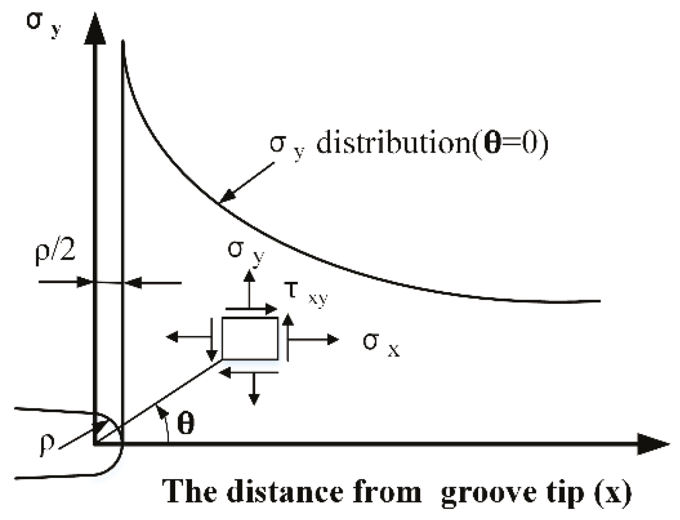
Due to the presence of cracking notch, different stress and strain fields at the root of the actual notch and the ideal crack tip are caused. Cracking in the notch of the connecting rod belongs to a passivation crack. The stress state in the root of the incision is shown in Figure 4, and stress field expression of the passivation crack tip is shown in Equation (1) [29].
Note that ρ is the radius of curvature of the root of the incision. σx, σy, σz, τxy, τxz, and τyz are the stress components. r and θ are the the polar coordinates of the point near the groove tip. υ is the Poisson’s ratio. is the stress intensity factor. For the root of the incision, θ = 0, and r = ρ/2. Substituting θ and r into (1) obtains
From Equation (2), the root of the incision is the uniaxial tension state, and the maximum tensile stress is equal to the first principal stress. The intensity factor value is only related to ρ and σy, if ρ is determined, when σy reaches a certain value, a crack will be formed at the root of the incision. At this time, has reached the extreme value of KI, that is, the material fracture toughness KIC. After the external force continues to increase to a certain value, the crack is unstable and expands. At this time, no external force is required, and the crack can be rapidly expanded to the fracture. The fracture-split of the connecting rod is an elastic-plastic small-scale yield fracture process, which conforms to the first joint strength theory. The crack initiation and expansion is a material failure process caused by the increase of stress [30]. The cause of the fracture is the quasi-brittle fracture caused by the maximum tensile stress. Therefore, the maximum tensile stress is used as the basic fracture failure criterion in the simulation calculation. In view of the complexity of the Formulae (1) and (2), only the stress and strain state of the crack front can be qualitatively described and the quantitative analysis cannot be performed. The structural displacement, stress-strain distribution, material fracture risk point and fracture direction characteristics all cannot be visually characterized. The finite element method can make up for the above defects well, therefore the finite element method is used to analyze the fracture-split process of the connecting rod.
2.4. Finite Element Simulation and Analysis
The ANSYS/LS-DYNA software is used to simulate the process of connecting rod fracture-split. ANSYS is a large-scale general finite element analysis software developed by ANSYS Corporation of the United States. It is the world’s fastest growing computer-aided engineering software. LS-DYNA is produced by LSTC/ETA Corporation of the United States and is the most famous universal explicit dynamic analysis program in the world. It is especially suitable for solving nonlinear dynamic impact problems of various 2D and 3D nonlinear structures such as high-speed collision, explosion, and metal forming. In order to enhance the competitiveness of the product, ANSYS cooperated with LS-DYNA, and integrated the LS-DYNA solver into ANSYS software.
2.4.1. Geometric Model Simplification
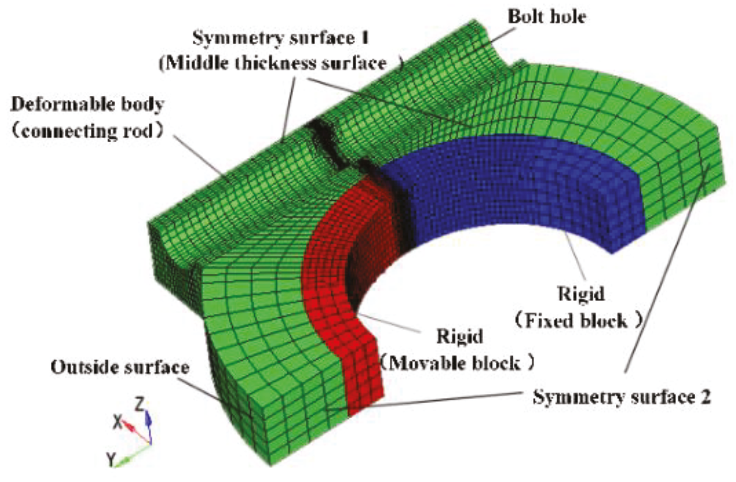
The connecting rod shaft and small end have no effect on the process of fracture-split, therefore the small head and rod shaft can be ignored. A quarter of the connecting rod big end is taken to build the model. The connecting rod is set as the deformable body. The movable block and fixed block are set as rigid bodies. In order to avoid a large number of unit failures leading to the calculation error, the transitional network method is used to divide the hexahedral mesh, and the mesh of the fracture area is encrypted, as shown in Figure 5.
2.4.2. Boundary Constraints and Loads
Symmetry plane 1 (middle thickness surface) and symmetry plane 2 (symmetrical plane of the axis of the connecting rod) are separately applied to the displacement constraint Uz = 0 and Ux = 0. A full constraint is applied to the rigid fixed block. The constraint on the rigid movable block is to limit all rotation and Uz = Ux = 0. Based on test data, the movable block applied to the speed load is of the Y direction in the simulation process.
2.4.3. Material Parameters and Fracture Criteria Setting
In the numerical simulation of the connecting rod fracture-splitting, ANSYS is used for pre-processing. The material definition, boundary constraints and loads are set, and the K file is generated. Then, the maximum principal stress fracture criterion is defined by adding keywords *MAT_ADD_EROSION in the K file. Finally, the K file is submitted to the LS-DYNA solver for solving. LS-DYNA sets the unit failure function and simulates the crack generation and expansion through the unit gradual demise. When the stress concentration at the root of crack notch causes the stress of a certain element to reach the set value (fracture stress σf), the element will fail and be deleted, so that the stress is redistributed and new stress concentration is induced. Multiple failed units penetrate sequentially, forming a crack growth process.
3. Results
3.1. Stress and Strain Field
The first principal stress distributions of the four important moments during the fracture-split process of the 36MnVS4 and C70S6 connecting rods are shown in Figure 6. Figure 6a shows the C70S6 connecting rod: a time of crack initiation t1 = 0 s, the start moment of crack growth t2 = 11.554 × 10⁻³ s. t3 = 11.556 × 10⁻³ s is the time that the crack extends to the bolt hole, and t4 = 11.562 × 10⁻³ s is the end time of crack propagation. Figure 6b is the corresponding time for the 36MnVS4 connecting rod: t1 = 0 s, t2 = 7.661 × 10⁻³ s, t3 = 7.663 × 10⁻³ s, and t4 = 7.671 × 10⁻³ s. At the time of the crack initiation (t1), the stress concentrations near the cracking groove of the C70S6 and 36MnVS4 connecting rods are significant, the stress distributions are both butterfly-like, and the high stress areas are both located in the groove root. In contrast, the stress concentration of the 36MnVS4 is more obvious than the C70S6. The yield strength of the 36MnVS4 is higher, its crack tip stress increases faster and the high stress region is more concentrated. And the fracture stress of the C70S6 and 36MnVS4 has little difference, therefore the 36MnVS4 is more prone to fracture. At the start moment of crack growth (t2), the stress concentration in the crack tip of the 36MnVS4 connecting rod is more obvious than the C70S6 connecting rod. At the time of crack extended to the bolt hole (t3), the maximum value of the first principal stress moves forward accompanied by the leading front of the crack, and the stress is released in the fracture portion. In contrast, the stress concentration near the crack tip of the 36MnVS4 is more pronounced. At the end moment of the crack propagation (t4), the most stress of the two connecting rods is released. The stress distribution of the 36MnVS4 connecting rod is more uniform.
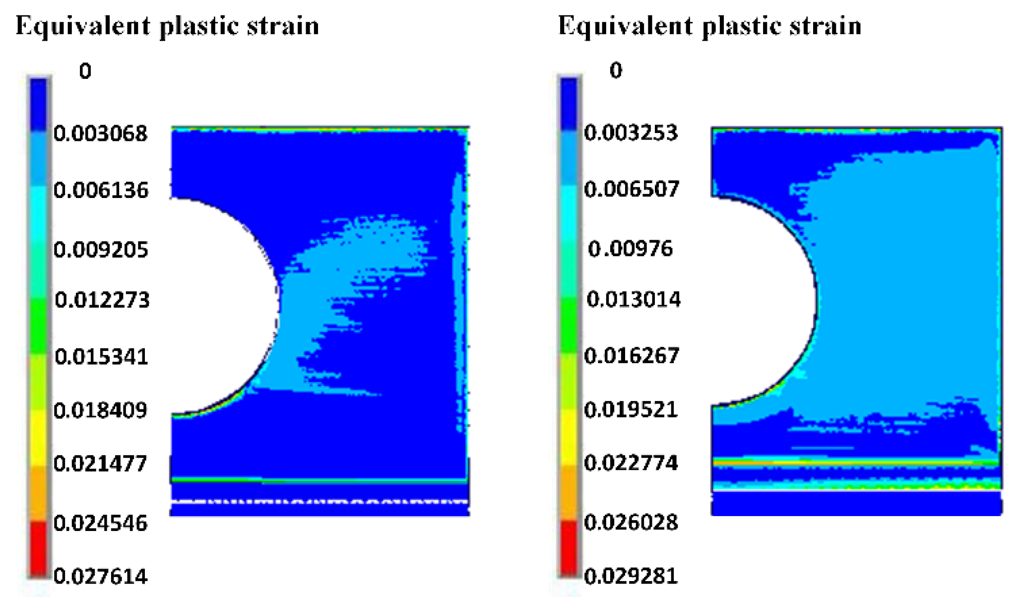
The plastic strain of two material connecting rods at the end of crack propagation is compared, as shown in Figure 7. It can be seen that the general trend of plastic deformation distribution of the 36MnVS4 and C70S6 connecting rod is consistent. The maximum plastic strain of the 36MnVS4 and C70S6 connecting rods is not much different. It can be seen that the plastic strain of the 36MnVS4 connecting rod at the bolt hole, the end face side is greater than that of the C70S6 connecting rod, and the plastic zone of the fracture surface of the 36MnVS4 connecting rod is also significantly larger than that of the C70S6 connecting rod. The plastic deformation range of the fracture surface of the 36MnVS4 connecting rod is greater than that of the C70S6 connecting rod, which makes the fracture surface of the 36MnVS4 connecting rod of poor quality and easy to tear. Therefore, the 36MnVS4 connecting rod is more prone to produce quality defects in the fracture-split process.
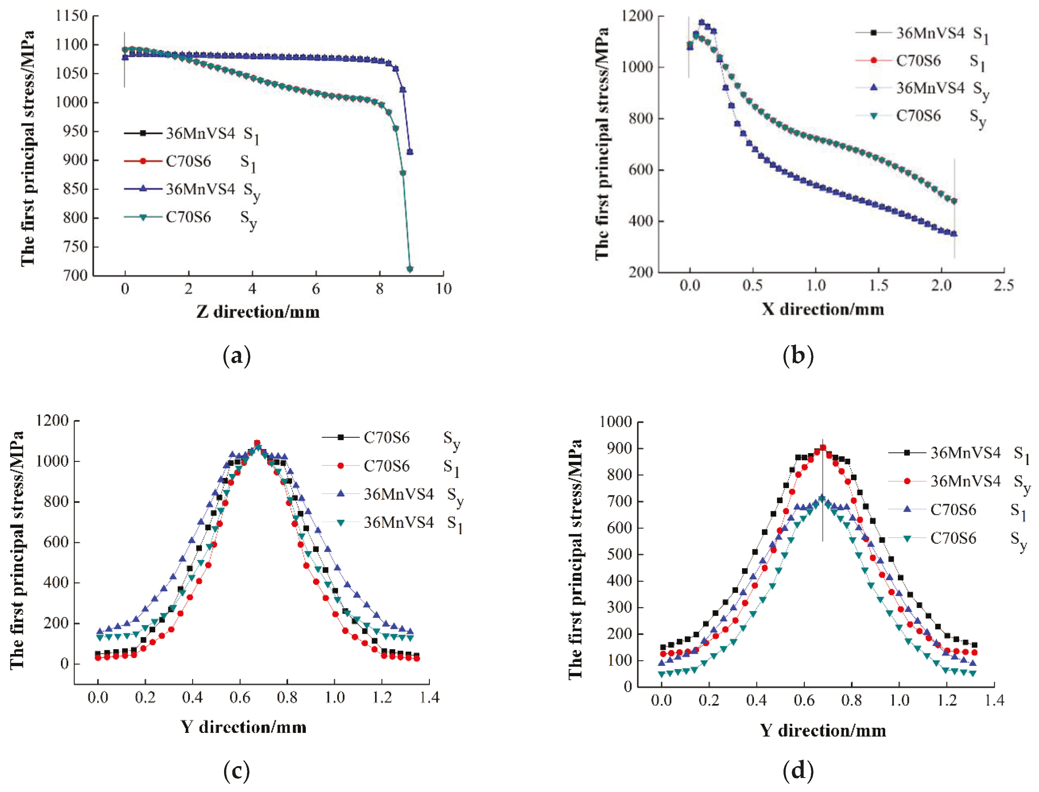
In order to further analyze the stress distribution near the crack groove at the time of crack initiation, the first principal stress and the Y-direction tensile stress of the characteristic Line 1 (groove root), Line 2 (leading edge of crack tip), Line 3 (v-type groove edge of middle thickness surface), and Line 4 (v-type groove edge of outside surface) are extracted. The characteristic lines positions are shown in Figure 8. In Figure 9a,b, it can be seen that the first principal stress and the Y-direction tensile stress of the two connecting rods are the same along the L1 and L2, which indicates that the crack propagation of the theoretical fracture surface conforms to the maximum principal stress criterion. Figure 9a shows that the stress of the C70S6 connecting rod from the middle thickness surface to the outside surface decreases rapidly, while the 36MnVS4 connecting rod is slower. This shows that along the thickness direction, the stress of the C70S6 connecting rod is more concentrated in the middle, and the 36MnVS4 stress distribution is more uniform. Therefore, the crack initiation point of the C70S6 tends to be the only, that is, crack in the middle thickness surface. The crack initiation point of the 36MnVS4 is scattered, and the crack initiation position at the root of the cracking groove is random and unstable.
Combined with Figure 9b and Figure 6, it can be seen that the stress peak appears at the near surface of middle thickness surface of the cracking groove. As the near surface is in the three-way stress state, where the element firstly reaches the fracture stress, the initial crack source is generated. The initial crack positions of the 36MnVS4 and C70S6 connecting rods are 0.16 mm and 0.09 mm distance from the root of the fracture-split groove, respectively, which indicates that the 36MnVS4 has a deeper crack initiation position. However, due to the presence of the root arc, the first principal stress drops slowly, which is more conducive to the initiation stress concentration and reduces the defects of crack deviation and bifurcation. As shown in Figure 9c,d, on the theoretical fracture surface (the root of the cracking groove), the stress concentration of Line 3 is higher than Line 4, and the stress difference of the C70S6 is higher than the 36MnVS4, which shows that the stress concentration of the C70S6 is more pronounced along the direction of the theoretical fracture. At the middle thickness surface (XY-plane), the stress difference of the C70S6 is also greater than 36MnVS4, so the stress of C70S6 is more concentrated. Combining the two directions, the C70S6 initiation point is more unique, and tends to fracture along the theoretical fracture surface, while the initial crack point of the 36MnVS4 is relatively scattered and uncertain.
3.2. Crack Initiation Time and Cracking Load
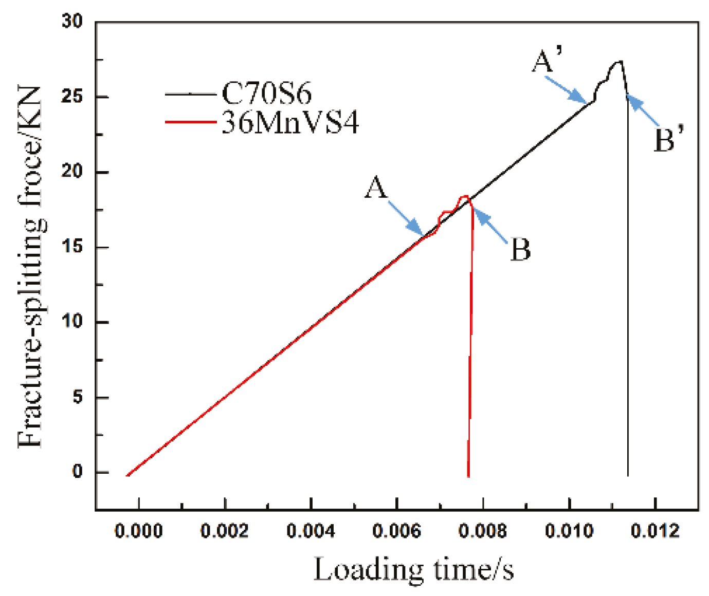
The change curves of the fracture-split force with time of the C70S6 and 36MnVS4 connecting rods are shown in Figure 10. The fracture-split forces required of the 36MnVS4 and C70S6 connecting rods are 19.6 KN and 27.6 KN, respectively. It can be seen that the crack initiation time (point A) of the 36MnVS4 is 7.661 × 10⁻³ s, and the end time of crack propagation (point B) is 7.671 × 10⁻³ s. The total time is 0.01 × 10⁻³ s. The crack initiation time (A’ point) of the C70S6 is 11.554 × 10⁻³ s, and the fracture ending time (B’ point) is 11.562 × 10⁻³ s. The total used time is 0.008 × 10⁻³ s. It can determine that the crack initiation time of the 36MnVS4 connecting rod is earlier, but crack growth of the C70S6 connecting rod is faster. The total crack expansion time of the 36MnVS4 connecting rod compared to the C70S6 connecting rod increases by nearly 20%, which increases the possibility of producing fracture-split defects in the crack propagation process of the 36MnVS4 connecting rod. Since the crack initiation of the 36MnVS4 is earlier than the C70S6, the notch sensitivity of the 36MnVS4 is much better than that of the C70S6.
4. Discussion
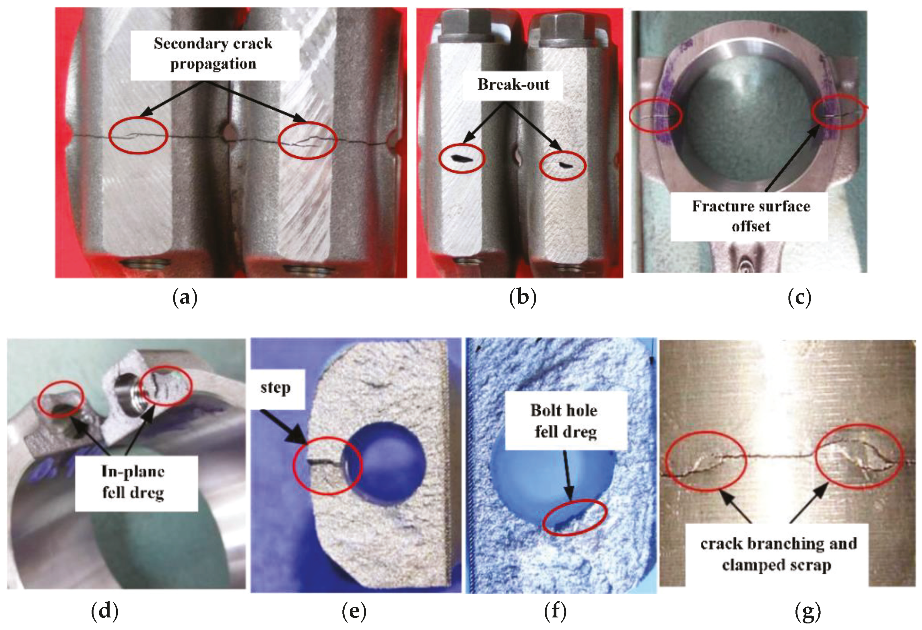
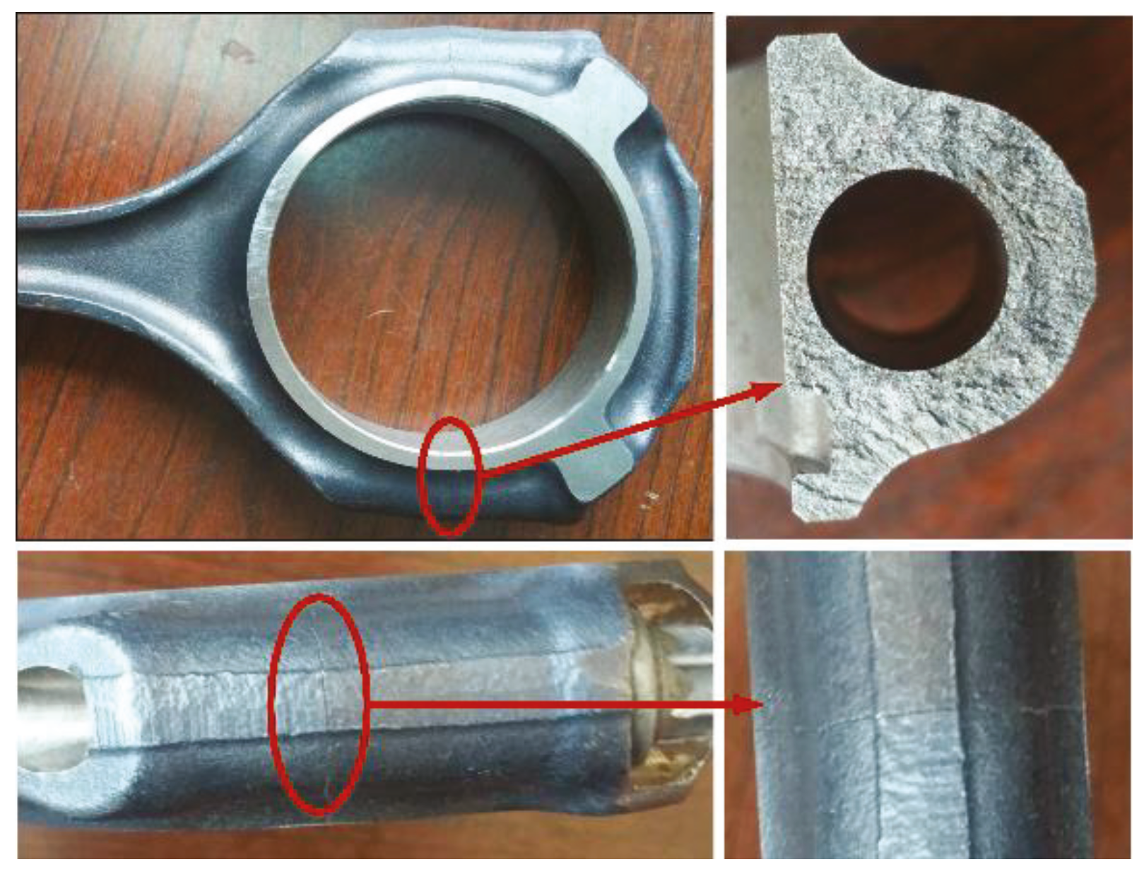
Through combined test results, the defects caused by the fracture-split of the 36MnVS4 connecting rods are found: obvious plastic block or fiber tear zones, crack bifurcation, and fell dregs and steps, as shown in Figure 11. The reasons that fracture-split defects of the 36MnVS4 connecting rods are produced are analyzed by simulation process and tests.
Through the analysis of the composition and microstructure of the two materials, it can be known that the carbon content of the 36MnVS4 is lower. The bulk ferrite structure is precipitated along the grain boundary and the proportion of ferrite is larger. The ferrite is a relatively soft phase, which makes the fracture surface in the process of fracture-splitting more prone to tear zones. This defect can be improved by controlling the cooling rate after forging, and increasing the content of C and certain alloy elements. If the cooling speed after forging of the connecting rod is accelerated, the time for the growth of the austenite grains is shortened, thereby reducing the amount of ferrite precipitation. Increasing the carbon content of the material can significantly improve the pearlite content, and increasing some alloying elements such as V, Ti, and other content can also significantly reduce the size and proportion of massive ferrite. Therefore, occurrence of fracture-split tear areas is decreased.
Compared with the crack propagation process of the two connecting rods, the 36MnVS4 connecting rod has a longer crack propagation time than the C70S6 connecting rod, and the fracture separation speed is 20% lower than that of the C70S6. The slower fracture separation rate increases the possibility of defects generation.
Compared with the C70S6 connecting rod, the crack initiation time of the 36MnVS4 connecting rod is earlier and cracking force is smaller, therefore the 36MnVS4 has higher gap sensitivity. In the machining process of the bolt holes and big end holes, if the processing tool becomes blunt, it will cause the machined surface to form a rolling micro-crack which is particularly pronounced for the materials with higher notch sensitivity. Micro-cracks are prone to secondary crack propagation and bifurcation during crack propagation as shown in Figure 11a. If the secondary crack occurs in the fracture surface, it will cause in-plane fell dregs or tear as shown in Figure 11d. If the secondary crack is on the edge of the bolt hole, it will induce the fell dregs phenomenon of bolt hole as shown in Figure 11f. If the secondary crack is on the outside surface of the connecting rod, it can cause crack branching and clamped scrap as shown in Figure 11g,b.
According to the stress analysis of the characteristic lines (Figure 9), it can be seen that the peak stress curve of the 36MnVS4 is gentler, which resulted in the crack initiation point of the connecting rod in the direction of thickness is random, scattered, and unstable. When the crack is again aggregated after bypassing the bolt hole, it may produce step or tear zone defects as shown in Figure 11e,d. These tend to cause a large fracture surface offset, as shown in Figure 11c. The above-mentioned defects are mainly related to the material properties that are difficult to completely avoid, but can be improved by improving the processing technology.
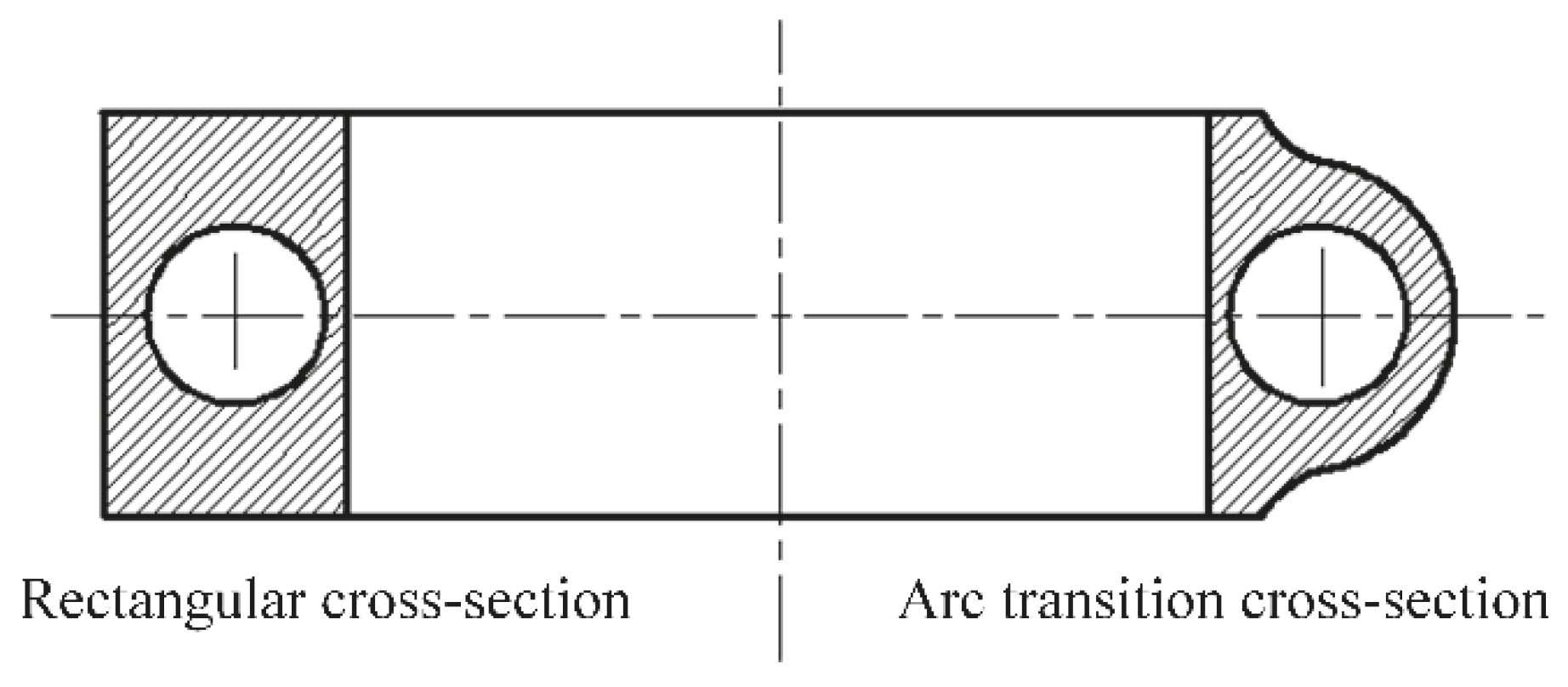
Based on the above results, it can be seen that the fracture-split defects of the 36MnVS4 connecting rod are mainly caused by the location of the crack initiation, the expansion speed, and the instability of the intersection. In addition to optimizing material properties, to improve the fracture-split quality of the 36MnVS4 connecting rod, it must change the mode of crack initiation and crack propagation, and guide the 36MnVS4 single point initiation and directional expansion and increase the crack propagation speed. For this reason, the changed the fracture cross-section design is shown in Figure 12. The rectangular cross-section increases the likelihood that the two cracks do not converge, and then causes break-out and clamped scrap defects. The outer edge of the fracture surface adopts the arc design, which will help the intersection of cracks in the same point, and can reduce the area of the fracture surface and increase crack propagation speed. The tearing, fell slags, and other defects of the fracture surface will be greatly reduced.
The fracture-splitting texts of the 36MnVS4 connecting rod with arc-shaped sections are conducted. Experimental results are shown in Figure 13. When the big end of the connecting rod is circular, it is clear that the fracture surface is more flat and has no obvious defects. It can be seen that the step defect on the crack convergence zone disappear, and the tearing phenomenon and fell slags at the fracture surface are also un-conspicuous. This indicates that the crack propagation process of the circular section connecting rod become more stable, and the quality of the fracture surface is remarkably improved. Therefore, changing the cross-sectional shape of the 36MnVS4 connecting rod can also reduce the fracture-split defects.
5. Conclusions
The 36MnVS4 has a higher yield ratio and better machinability than the C70S6. The 36MnVS4 has lower carbon content and more ferrite, therefore the fracture surface of 36MnVS4 connecting rod is more prone to tears.
Compared with the C70S6 connecting rod, the crack initiation time of the 36MnVS4 connecting rod is earlier, but the fracture-split speed of C70S6 is larger. And the fracture separation speed is 20% lower than that of the C70S6. The slower fracture separation rate increases the possibility of defects generation.
The crack initiation position of the 36MnVS4 connecting rod is random, scattered, unstable, and the 36MnVS4 has higher gap sensitivity. The plastic deformation range of the fracture surface of the 36MnVS4 connecting rod is greater than that of the C70S6 connecting rod. Therefore, the 36MnVS4 connecting rod is more prone to produce quality defects in the fracture-split process.
By changing the cross-section design, the outer edge of the joint surface is changed to arc-shaped, which can improve the fracture-split process of the 36MnVS4 and reduce the processing defects.
Author Contributions
Zhou Shi and Shuqing Kou conceived and designed the study. The numerical simulation and experiment have been developed by Zhou Shi. Discussion and conclusions have been written with the contribution of Zhou Shi and Shuqing Kou.
Funding
This research was financially supported by National Key Research and Development Plan of China (2016YFD0701102) and National Science and Technology Major Project of China (2013ZX04002021).
Acknowledgments
The authors would like to thank teacher Yong Zhao, Jilin University for his help to the research and thank Bolong Wang, Shandong University of Technology for support during the Finite Element Analysis.
Conflicts of Interest
The authors declare no conflict of interest.
References
- Gu, Z.; Yang, S.; Ku, S.; Dai, X. Fracture-split technology of automobile engine connecting rod. Int. J. Adv. Manuf. Technol. 2005, 25, 883–887. [Google Scholar] [CrossRef]
- Kou, S.Q.; Gao, Y.; Gao, W.Q. The influence of auxiliary gases in the optimized analysis of pulsed laser grooving of a C70S6 connecting rod for fracture splitting. Results Phys. 2017, 7, 628–635. [Google Scholar] [CrossRef]
- Fukuda, S.; Eto, H. Development of fracture splitting connecting rod. JSAE Rev. 2002, 23, 101–104. [Google Scholar] [CrossRef]
- Shi, Z.; Kou, S.Q. Analysis of quality defects in the fracture surface of fracture splitting connecting rod based on three-dimensional crack growth. Results Phys. 2018, 10, 1022–1029. [Google Scholar] [CrossRef]
- Shi, Z.; Kou, S.Q. Inverse reconstruction of fracture splitting connecting rod and its strength and fatigue life. J. Fail. Anal. Prev. 2018, 18, 619–627. [Google Scholar] [CrossRef]
- Kou, S.Q.; Song, W.F.; Shi, Z. Fracture splitting simulation and defect analysis of 36MnVS4 connecting rod. J. Jilin Univ. 2017, 47, 861–868. [Google Scholar]
- Manouchehrian, A.; Marji, M.F. Numerical analysis of confinement effect on crack propagation mechanism from a flaw in a pre-cracked rock under compression. Acta Mech. Sin. 2012, 28, 1389–1397. [Google Scholar] [CrossRef]
- Zhang, X.; Cai, Q.; Zhou, G.; Chen, Q.; Xiong, Y. Microstructure and mechanical properties of V–Ti–N microalloyed steel used for fracture-split connecting rod. J. Mater. Sci. 2011, 46, 1789–1795. [Google Scholar] [CrossRef]
- Kim, H.S.; Kim, T.G.; Chung, T.J.; Kim, H.S.; Hong, S.-J. Fatigue characteristics of high strength C70S6 and SMA40 steels. Mater. Sci. Eng. A 2010, 527, 2813–2818. [Google Scholar] [CrossRef]
- Hui, W.; Chen, S.; Zhang, Y.; Shao, C.; Dong, H. Effect of vanadium on the high-cycle fatigue fracture properties of medium-carbon microalloyed steel for fracture splitting connecting rod. Mater. Des. 2015, 66, 227–234. [Google Scholar] [CrossRef]
- Lipp, K.; Kaufmann, H. Die and powder forging materials for automotive connecting rods. MTZ Worldw. E Mag. 2011, 72, 70–75. [Google Scholar] [CrossRef]
- Bariani, P.F.; Bruschi, S. Modelling the forging and post-forging cooling of C70S6 conrods. J. Mater. Process. Technol. 2005, 167, 529–535. [Google Scholar] [CrossRef]
- Liang, J.; Zhao, Z.; Wu, H.; Peng, C.; Sun, B.; Guo, B.; Liang, J.; Tang, D. Mechanical behavior of two ferrite–martensite dual-phase steels over a broad range of strain rates. Metals 2018, 8, 236. [Google Scholar] [CrossRef]
- Chen, T.C.; Chen, S.T.; Tsay, L.W.; Shiue, R.K. Correlation between fatigue crack gowth behavior and fracture surface roughness on cold-rolled austenitic stainless steels in gaseous hydrogen. Metals 2018, 8, 221. [Google Scholar] [CrossRef]
- Rodríguez-Martínez, J.A.; Rusinek, A.; Arias, A. Thermo-viscoplastic behaviour of 2024-T3 aluminium sheets subjected to low velocity perforation at different temperatures. Thin-Walled Struct. 2011, 49, 819–832. [Google Scholar] [CrossRef] [Green Version]
- Rodríguez-Millán, M.; Vaz-Romero, A.; Rusinek, A.; Rodríguez-Martínez, A.; Arias, A. Experimental study on the perforation process of 5754-H111 and 6082-T6 aluminium plates subjected to normal impact by conical, hemispherical and blunt projectiles. Exp. Mech. 2014, 54, 729–742. [Google Scholar] [CrossRef]
- Rodríguez-Martínez, J.A.; Rusinek, A.; Chevrier, P.; Bernier, R.; Arias, A. Temperature measurements on ES steel sheets subjected to perforation by hemispherical projectiles. Int. J. Impact Eng. 2010, 37, 828–841. [Google Scholar] [CrossRef] [Green Version]
- Song, W.F. Performance Comparison and Notch Parameter Selection on Con-Rod Fracture Splitting Machining of 36MnVS4 and C70S6. Master’s Thesis, Jilin University, Changchun, China, 2017. [Google Scholar]
- Dumstorff, P.; Meschke, G. Crack propagation criteria in the framework of X-FEM-based structural analyses. Int. J. Numer. Anal. Methods Geomech. 2007, 31, 239–259. [Google Scholar] [CrossRef]
- Wang, B.; Li, M.; Yang, Y.; Liu, Z.; Liu, H. Numerical simulation of multilayer stagger-split die and experiment on the bearing capacity. High Press. Res. 2015, 35, 388–395. [Google Scholar] [CrossRef]
- Gajewski, J.; Sadowski, T. Sensitivity analysis of crack propagation in pavement bituminous layered structures using a hybrid system integrating artificial neural networks and finite element method. Comput. Mater. Sci. 2014, 82, 114–117. [Google Scholar] [CrossRef]
- Agarwal, P.; Gupta, A.; Saxena, V. A Comparative study of different materials of connecting rod: A review. Int. J. Mech. Eng. 2015, 5, 54–57. [Google Scholar]
- Yang, H.; Kou, S.Q.; Gao, W.; Zhang, P. Analysis on technology and defects of fracture-split of automobile engine connecting rod. Proc. Inst. Mech. Eng. Part B J. Eng. Manuf. 2015, 229, 1603–1613. [Google Scholar] [CrossRef]
- Zhao, Y. Study on Parameters of Connecting Rod Fracture Splitting Based on Fracture after Small Scale Yielding and Its Application. Ph.D. Thesis, Jilin University, Changchun, China, 2011. [Google Scholar]
- Westergaard, H.M. Bearing pressures and crack. J. Appl. Mech. 1939, 6, A49–A53. [Google Scholar]
- Wang, B.; Li, M.; Yang, Y.; Liu, Z. Note: Double-beveled multilayer stagger-split die for a large volume high-pressure apparatus. Rev. Sci. Instrum. 2015, 86, 086106. [Google Scholar] [CrossRef] [PubMed]
- Blackburn, W.S. Conditions for onset of crack propagation in elastic plastic materials. Int. J. Fract. 1970, 6, 211–212. [Google Scholar] [CrossRef]
- Güler, S.; Fischer, A. Fatigue behavior of cold-worked high-interstitial steels. Metals 2018, 8, 442. [Google Scholar] [CrossRef]
- Irwin, G.R. Analysis of stresses and strains near the end of a crack traversing a plate. J. Appl. Mech. 1957, 24, 361–364. [Google Scholar]
- Rose, L.R.F. Recent theoretical and experimental results on fast brittle fracture. Int. J. Fract. 1976, 12, 799–813. [Google Scholar]
Figure 1.
Connecting rod fracture-split process.

Figure 2.
Optical microstructure of the tested steels: (a) C70S6; (b) 36MnVS4.

Figure 3.
Tensile test curves.
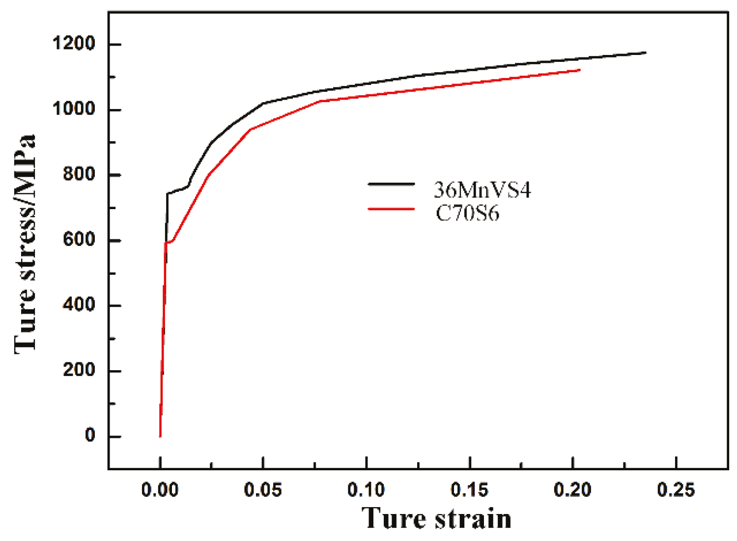
Figure 4.
The stress state of the incision′s root.

Figure 5.
Model diagram.

Figure 6.
The first principal stress distribution of the connecting rods: (a) C70S6; (b) 36MnVS4.
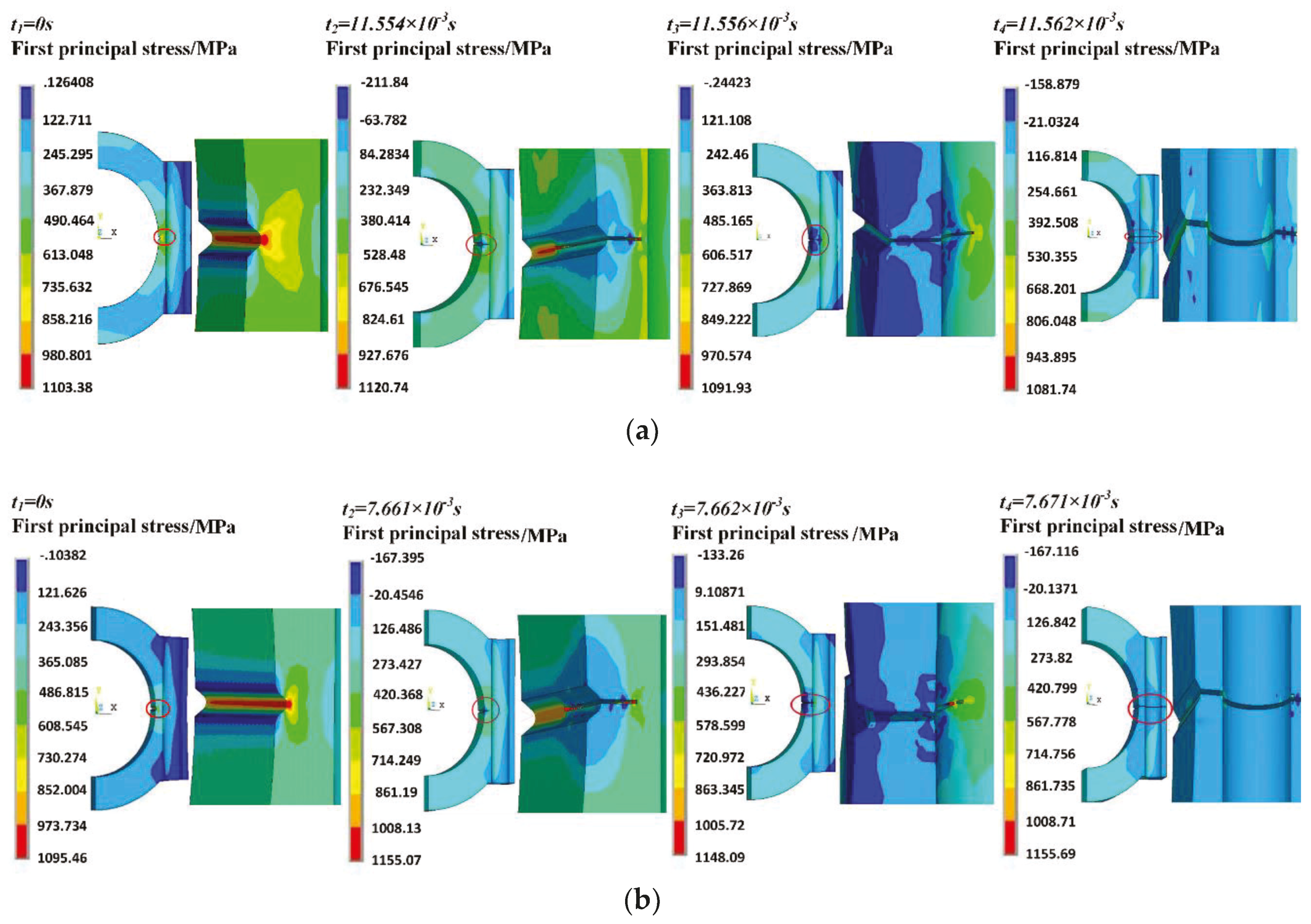
Figure 7.
The plastic strain of the fracture surface: (a) C70S6; (b) 36MnVS4.

Figure 8.
Feature lines.
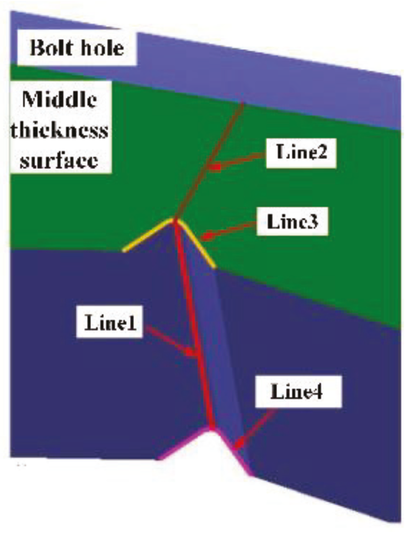
Figure 9.
The stress of the feature lines in crack initiation: (a) Line 1; (b) Line 2; (c) Line 3; (d) Line 4.
Figure 9.
The stress of the feature lines in crack initiation: (a) Line 1; (b) Line 2; (c) Line 3; (d) Line 4.

Figure 10.
The curve of fracture-split force and time.

Figure 11.
Fracture-splitting defects of the 36MnVS4 connecting rod: (a) crack bifurcation; (b) break-out; (c) fracture surface offset; (d) in-plane fell dregs; (e) step; (f) bolt hole fell dregs; (g) crack branching and clamped scrap.
Figure 11.
Fracture-splitting defects of the 36MnVS4 connecting rod: (a) crack bifurcation; (b) break-out; (c) fracture surface offset; (d) in-plane fell dregs; (e) step; (f) bolt hole fell dregs; (g) crack branching and clamped scrap.

Figure 12.
Cross-section design.

Figure 13.
Experimental results of connecting rod fracture-split.


Table 1.
Material chemical compositions (%).
| Material | C | Mn | Si | S | V | P | Cr | Mo |
|---|---|---|---|---|---|---|---|---|
| C70S6 | 0.71 | 0.52 | 0.22 | 0.06 | 0.03 | 0.045 | 0.20 | 0.02 |
| 36MnVS4 | 0.34 | 0.99 | 0.66 | 0.043 | 0.26 | 0.024 | 0.23 | 0.059 |
Table 2.
Mechanical Properties.
| Material | Elasticity Modulus E/MPa | Poisson’s Ratio υ | Yield Strength σs/MPa | Tensile Strength σb/MPa | Fracture Stress σf/MPa |
|---|---|---|---|---|---|
| C70S6 | 2.1 × 10⁵ | 0.27 | 592 | 932 | 1125 |
| 36MnVS4 | 2.08 × 10⁵ | 0.27 | 742 | 998 | 1175 |
© 2018 by the authors. Licensee MDPI, Basel, Switzerland. This article is an open access article distributed under the terms and conditions of the Creative Commons Attribution (CC BY) license (http://creativecommons.org/licenses/by/4.0/).
Share and Cite
MDPI and ACS Style
Shi, Z.; Kou, S. Study on Fracture-Split Performance of 36MnVS4 and Analysis of Fracture-Split Easily-Induced Defects. Metals 2018, 8, 696. https://doi.org/10.3390/met8090696
AMA Style
Shi Z, Kou S. Study on Fracture-Split Performance of 36MnVS4 and Analysis of Fracture-Split Easily-Induced Defects. Metals. 2018; 8(9):696. https://doi.org/10.3390/met8090696
Chicago/Turabian StyleShi, Zhou, and Shuqing Kou. 2018. "Study on Fracture-Split Performance of 36MnVS4 and Analysis of Fracture-Split Easily-Induced Defects" Metals 8, no. 9: 696. https://doi.org/10.3390/met8090696
Note that from the first issue of 2016, this journal uses article numbers instead of page numbers. See further details here.