Mechanisms for Improvement of Weld Appearance in Autogenous Fiber Laser Welding of Thick Stainless Steels


1
Key Laboratory of Lightweight and Reliability Technology for Engineering Vehicle, Education Department of Hunan Province, Changsha University of Science and Technology, Changsha 410114, China
2
College of Materials and Metallurgical Engineering, Guizhou Institute of Technology, Guiyang 550003, China
3
State Key Laboratory of Advanced Design and Manufacturing for Vehicle Body, Hunan University, Changsha 410082, China
4
Department of Civil and Mechanical Engineering, Purdue University Fort Wayne, Fort Wayne, IN 46805, USA
*
Author to whom correspondence should be addressed.
Metals 2018, 8(8), 625; https://doi.org/10.3390/met8080625
Submission received: 20 July 2018
/
Accepted: 7 August 2018
/
Published: 9 August 2018
Abstract
:High-power fiber laser welding is an efficient and effective way to produce heavy section structures. However, there is a significant challenge in producing the welds with free of imperfections such as nail-head-shaped welds, spatters, and root sagging. This is partially due to a lack of understanding of the welding mechanism of high-power fiber laser. In this paper, we were especially interested in the mechanism to improve the appearance of welds, and we focused on the autogenous laser welding on thick stainless steel plates by a 10 kW fiber laser. To look into the relations of process parameters and the quality of welds, a high-speed imaging system was applied to observe the molten pool flow and vapor plume during the welding process. The appearances of welds subjected to different welding conditions were analyzed. The results showed that (1) nail-head-shaped welds were suppressed by using a gas jet during laser welding process. (2) In the forward welding, a gentle upwelling molten metal flow on the rear keyhole wall, a deeper weld pool and a weaker vapor plume resulted in no spatter. (3) The gravity affected the formation of underfills and root sagging significantly during autogenous laser welding of thick plates. (4) When the workpiece was placed vertically in the transverse position, the welding process was stable without an aggregation of molten melt at the back surface. Moreover, the mechanisms of forming root sagging and humps were different at the top surface.
1. Introduction
As the 10 kW level high-power laser became commercially since 2005 [1], it has made it feasible to perform autogenous welding on thick-plates with single pass [2]. In contrast to conventional arc welding processes, the welding operation with high-power laser has a number of advantages including lower heat input, higher welding speed, and deeper penetration. However, it proves challenging to achieve satisfactory appearance of autogenous welds on the specimen with a thick plate; some common imperfections occurring with welds include nail-head-shaped welds, spatters, underfills, and root humps [3,4,5,6,7].
During laser welding for deep penetration, a nail-head-shaped weld refers to a weld whose width on the top surface is bigger than that on the bottom surface. A wider welding width creates a poor surface appearance. Furthermore, there were heat-affected zone (HAZ) cracks generated on grain boundaries in HAZ adjacent neck region of nail-head-shaped weld [8]. Rai et al. [9] found that possible causes of a nail-head shaped weld were (1) the thermal radiation of the ejected vapor plume on the weld pool surface and (2) the upward flow of the molten metal driven by the Marangoni convection and the evaporation recoil pressure. Zacharia et al. [10] argued that the Marangoni convection by the surface tension was the main reason to widen the upper pool of weld. They carried out numerical simulation to verify that the Marangoni convection drove the melt flow from center to side of the weld pool, this caused the formation of a nail-head-shaped weld. To address this issue, Bachmann et al. [11] applied a constant magnetic field so that the flow of weld pool was changed to avoid the formation of a nail-head-shaped weld.
A spatter is a general defect corresponding to an unsteady appearance of the weld seam. On the one hand, spatters falling on the specimen surface burn the surface material and create a poor surface appearance. On the other hand, ejection of spatters was accompanied by formation of underfill, undercuts, craters, and blowouts, which can severely reduce the mechanical properties of a weld [12]. Semak and Matsunawa [13] found that the vaporization recoil pressure ejected the melt from the interaction zone which further formed the spatter. Kawahito et al. [6] investigated the behavior of melt pools and spattering at a high speed, and found that the spatter was formed mainly by a strong shear force of the vapor plume. Kaplan and Powell [12] reviewed the spatter phenomena in laser welding and discovered the basic sequence where a spatter was generated.
A root hump is characterized by the formation of metal spheroids at the bottom surface of weld [14]. For an autogenous laser welding, Guo et al. [15] found that it was difficult to achieve the satisfactory quality of welds without using a weld pool supporting system [11]. The melt was pressured towards the bottom surface to form root humps of welds [16,17]. Moreover, it was proven that some factors, such as the difference of absorptivity and a laser with a wavelength of 1 µm (i.e., fiber, disc, and yttrium aluminum garnet (YAG)) would accelerate the melt flow to the keyhole exits more than conventional CO2 lasers with a wavelength of 10 µm [18]. Haug et al. [19] also confirmed that the welding by CO2 lasers was more robust and less susceptible for the formation of root humps.
It is still very challenging to eliminate poor weld appearance in autogenous laser welding of thick plates. Therefore, we are highly motivated to investigate the improvement of the weld appearance during autogenous laser welding of thick stainless steel plates. To examine the mechanisms of improving the weld appearance in detail, a high-speed imaging system was applied to observe the keyhole and melt flow and pool in high-power fiber laser welding. Finally, the mechanisms of the improvement of weld appearance were discussed.
2. Design of Experiments (DoE)
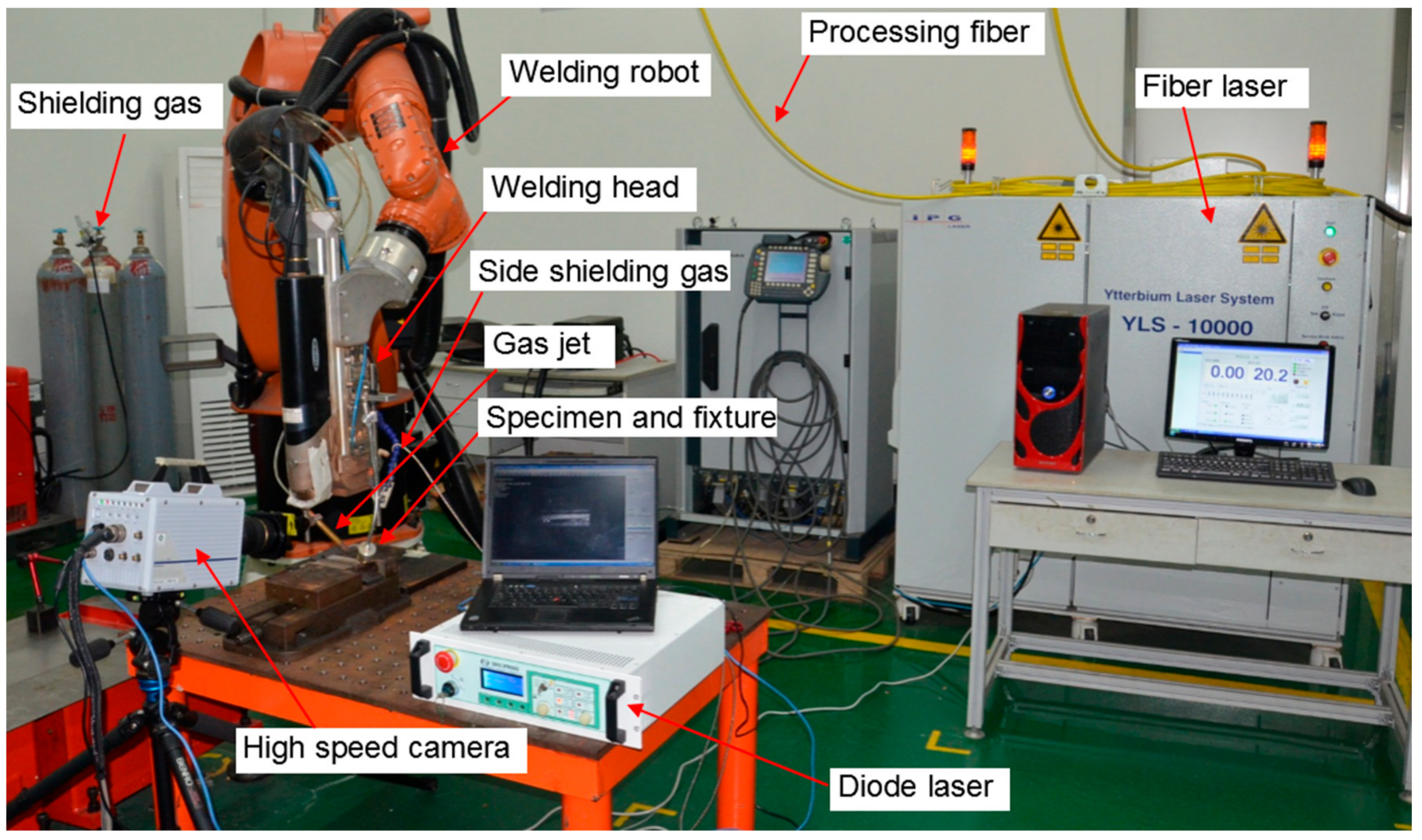
Figure 1 shows the setup of experiments. The selected laser source was a continuous wave fiber laser (YLS–10000, IPG Photonics, MA, USA) with a maximum power of 10 kW and beam parameter product of 7.5 mm⋅mrad with a processing fiber 200 µm in diameter. The laser beam emitted from the end of the optical fiber was collimated by a lens with a focal length of 150 mm. It was then focused on the specimen surface using another lens with a focal length of 300 mm. The focal length is the distance between the lens and the focal point. The defocus value is generally defined as the distance between the focal plane and the specimen surface. A positive (negative) defocus is obtained when the focal plane is above (below) the specimen surface; the defocus is zero when the focus point is on the specimen surface.
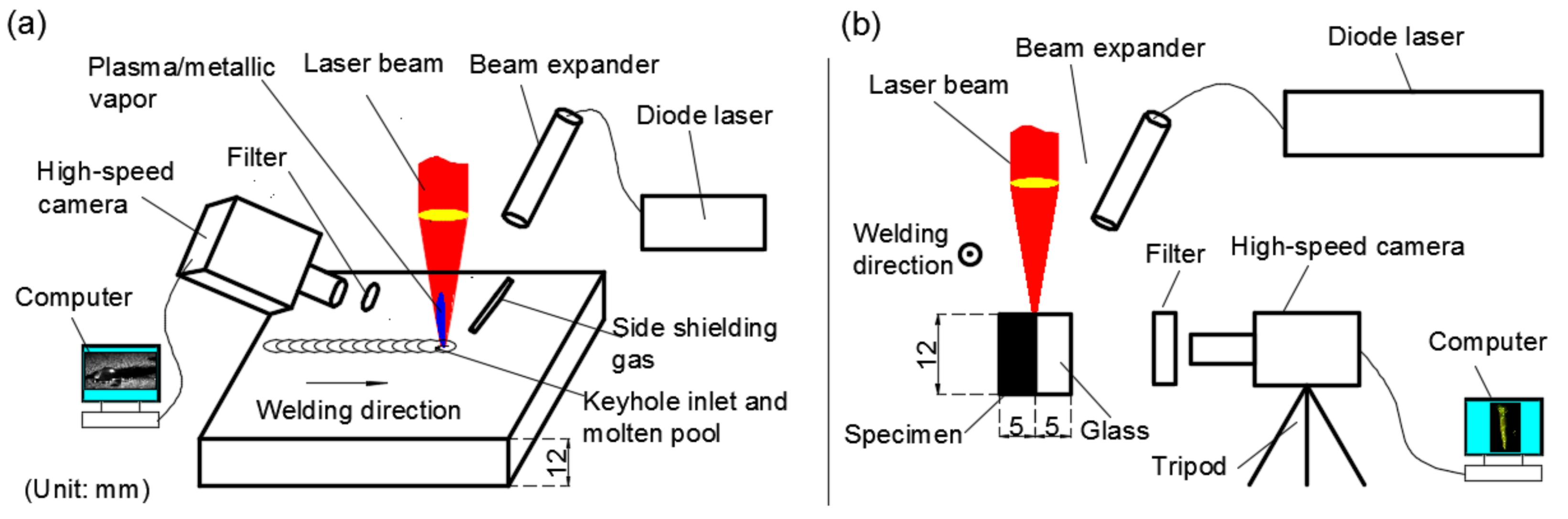
The materials to be welded were Type 304 austenitic stainless steel plates. The thicknesses of stainless steel plates were 12 mm and 15 mm for bead-on-plate welding; and 5 mm thick stainless steel plates were used for the modified ‘sandwich’ sample. The experimental setup of bead-on-plate welding and welding with the modified ‘sandwich’ sample was illustrated in Figure 2 [20,21]. A 12 mm stainless steel sheet was used for the bead-on-plate welding, as illustrated in Figure 2a. One sheet of stainless steel with the measuring 40 mm× 12 mm × 5 mm and one sheet of GG17 glass (Sanxin Quartz Glass Factory, Changsha, China) of the same size were aligned and clamped by a jig, to form a modified ‘sandwich’ sample, as shown in Figure 2b. The experimental parameters are listed in Table 1. The laser power (p) was 10 kW unchangeably. There were two types of welding gas supply. The shielding gas was nitrogen supplied from the side for protecting the molten pool at high temperature. The gas jet was argon supplied from the side for expending the keyhole entrance. The diameter of the gas jet nozzle was 2 mm, and the inclining angles were adjustable. The flow rate was 25 L/min. The dynamic pressure of the gas jet was a few kPa at the exit of the nozzle.
During high-speed imaging experiments, a high-speed camera was used with the frame rate ranging from 5000 fps (frames per second) to 20,000 fps. As can be seen from Figure 2, the high-speed camera was positioned laterally and mounted horizontally to observe the surface melt pool, the longitudinal keyhole and melt pool, respectively. For the sake of observing the molten pool, a 30 W diode laser with a wavelength of 808 nm was used to irradiate the welding zone. Correspondingly, a filter with a passband of 808 ± 3 nm was mounted in front of the camera lens.
After the welding process, the samples of typical cross sections were cut and prepared by electro-discharge machining (EDM). The samples were prepared by (1) polishing with abrasive papers and diamond slurry and (2) being etched by a solution of aqua regia (HCl:HNO3 = 3:1). A stereoscope (S6 D, LEICA Camera AG, Wetzlar, Germany) was applied to examine the macrostructure of welds.
3. Results and Discussion
3.1. Effect of Gas Jet on Formation of Nail-Head-Shaped Weld
3.1.1. Weld Appearance
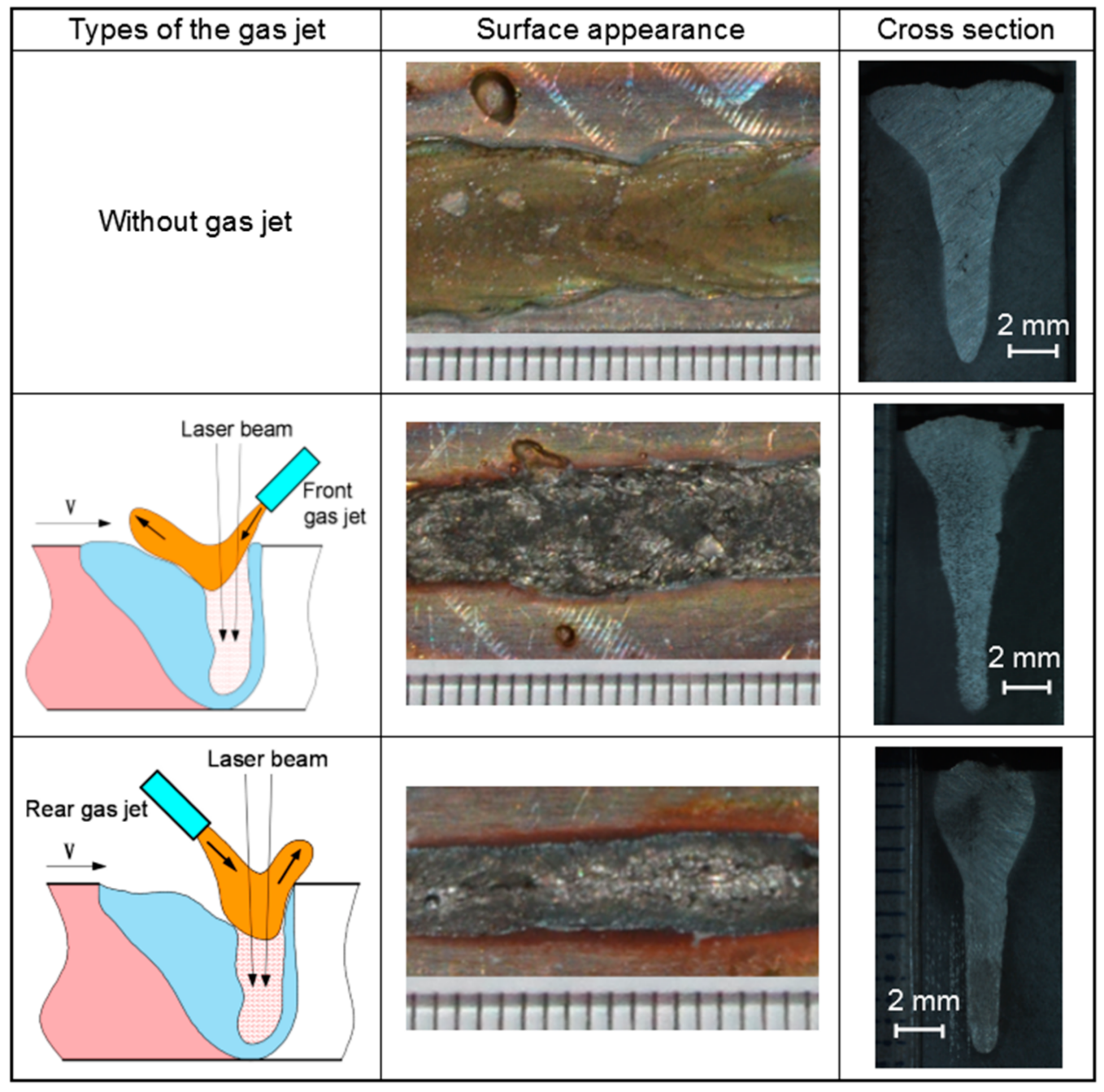
Figure 3 shows the relation of the configuration of the gas jet with the appearance of welds when 15 mm thick plates was welded. The gas flow with a high speed expelled from the jet was pointed to the keyhole entrance, and then changed the melt flow of the welding pool [22,23]. For the case without a gas jet, the width of the weld on top surface was broad, the depth of weld penetration was shallow slightly with a value of 11.41 mm, and a typical nail-head-shaped weld was generated. However, when the gas jet was applied, the width of weld on the top surface was narrower, and the weld was penetrated was deeper with a penetration depth of 11.56 mm, and the nail-head-shaped weld was not obvious. In particular, the weld width on the top surface was the narrowest with a rear gas jet. Welding spatter was also suppressed when the gas jet was used.
3.1.2. Control Mechanism of Nail-Head-Shaped Weld with a Gas Jet
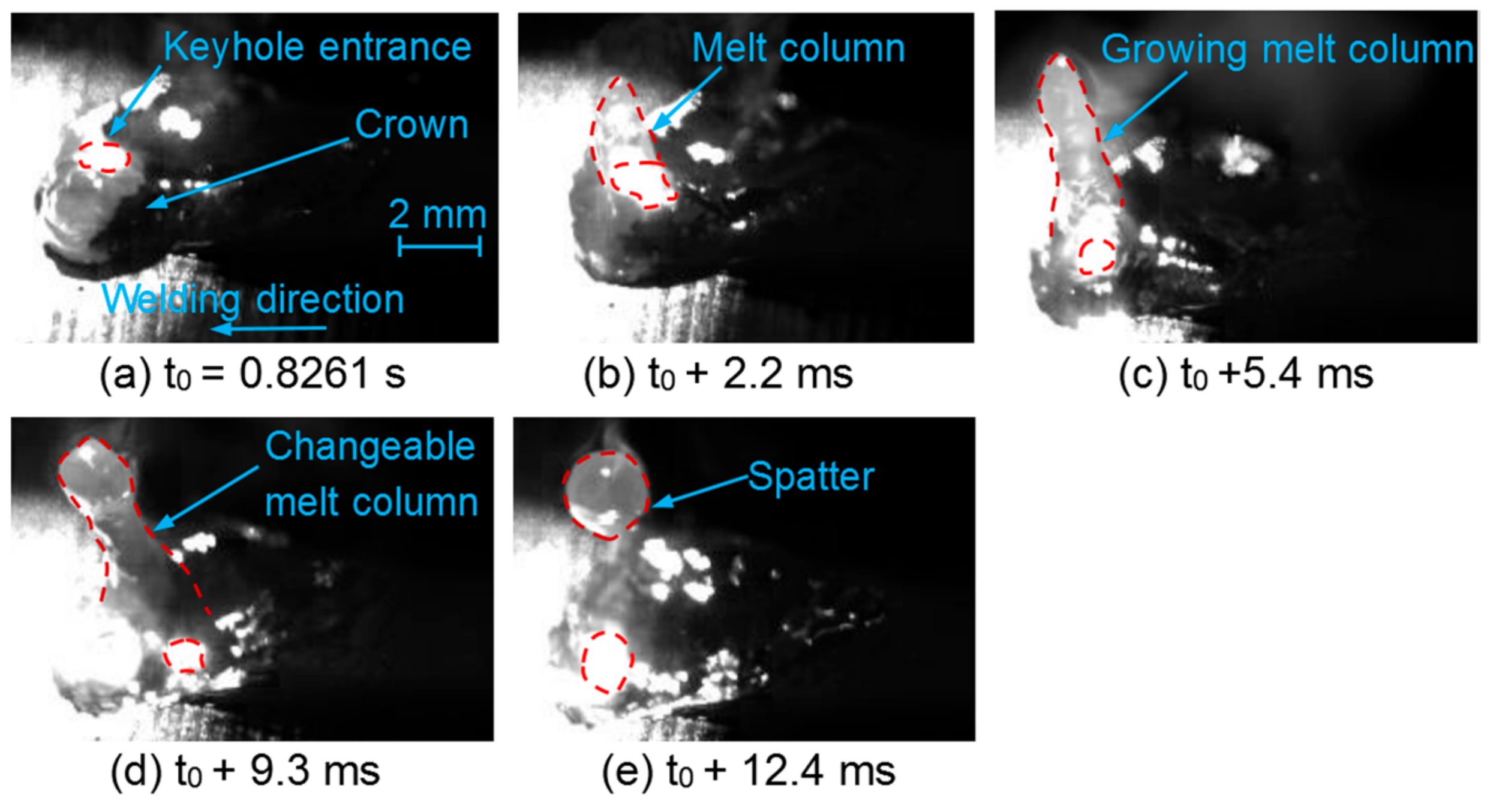
Figure 4 shows the images of the keyhole entrance and surface weld pool without a gas jet. Figure 4a shows that the keyhole entrance was small, the molten metal was swelled around the keyhole entrance, and the ‘crown’ of the molten metal was formed [24]. As the welding process progressed, a melt column was generated and it was accompanied by a rapid rise of a local molten metal at the front keyhole wall with a velocity of ~0.5 m/s; Figure 4b,c show that the melt column was elongated continuously, and the raised melt column was further grown and changed in Figure 4c,d. Thereby, the tip of the melt column became a spherical droplet, which was then separated from the melt column eventually. The residual melt column was pulled back into the molten pool flowing toward the rear keyhole (Figure 4d,e).
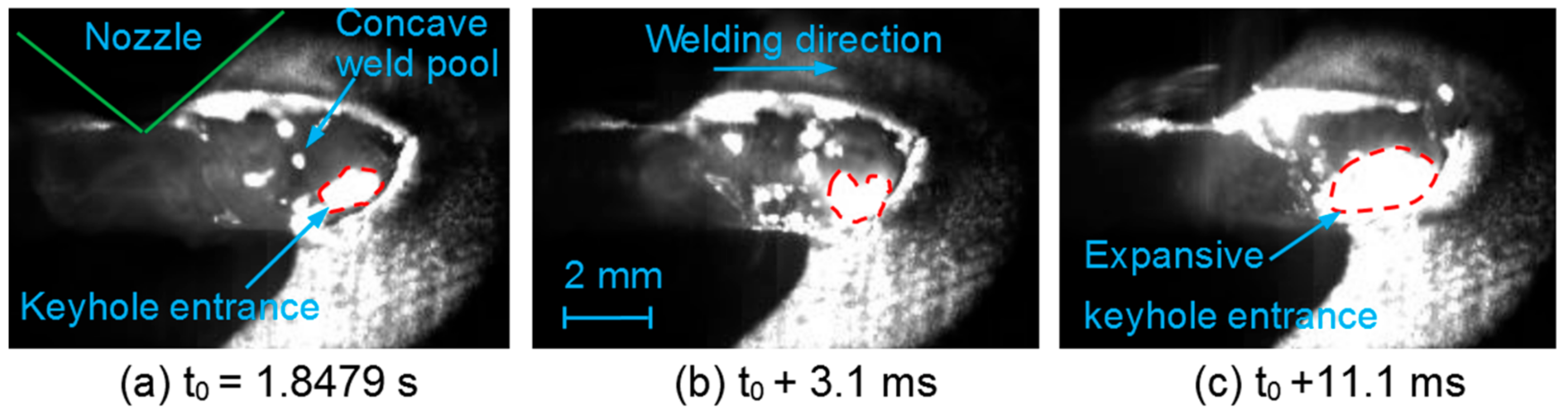
Figure 5 and Figure 6 show the images of the keyhole entrance and surface weld pool with a gas jet. When a front gas jet or a rear gas jet was used, the keyhole entrance was larger, and the melt flow around the keyhole entrance was stable. The thickness of the molten layer at front of the keyhole was thin, and there was not upward swelling of the molten metal around the keyhole entrance in contrast to the case without a gas jet. The molten metal at rear of the keyhole flowed backwards quickly enough to avoid the formation of spatter. Particularly, the melt pool around the keyhole entrance was concave with a rear gas jet (Figure 6). The keyhole entrance was expanded visibly in the opposite direction of welding with a rear gas jet (Figure 6c). These observations indicated that the Marangoni convection at the upper weld pool had been suppressed by the fast backwards melt flow around a larger keyhole entrance [9,10]. Consequently, the nail-head-shaped weld had been controlled to some extent.
3.2. Effect of Laser Incident Angle on Formation of Spatters
3.2.1. Weld Appearance
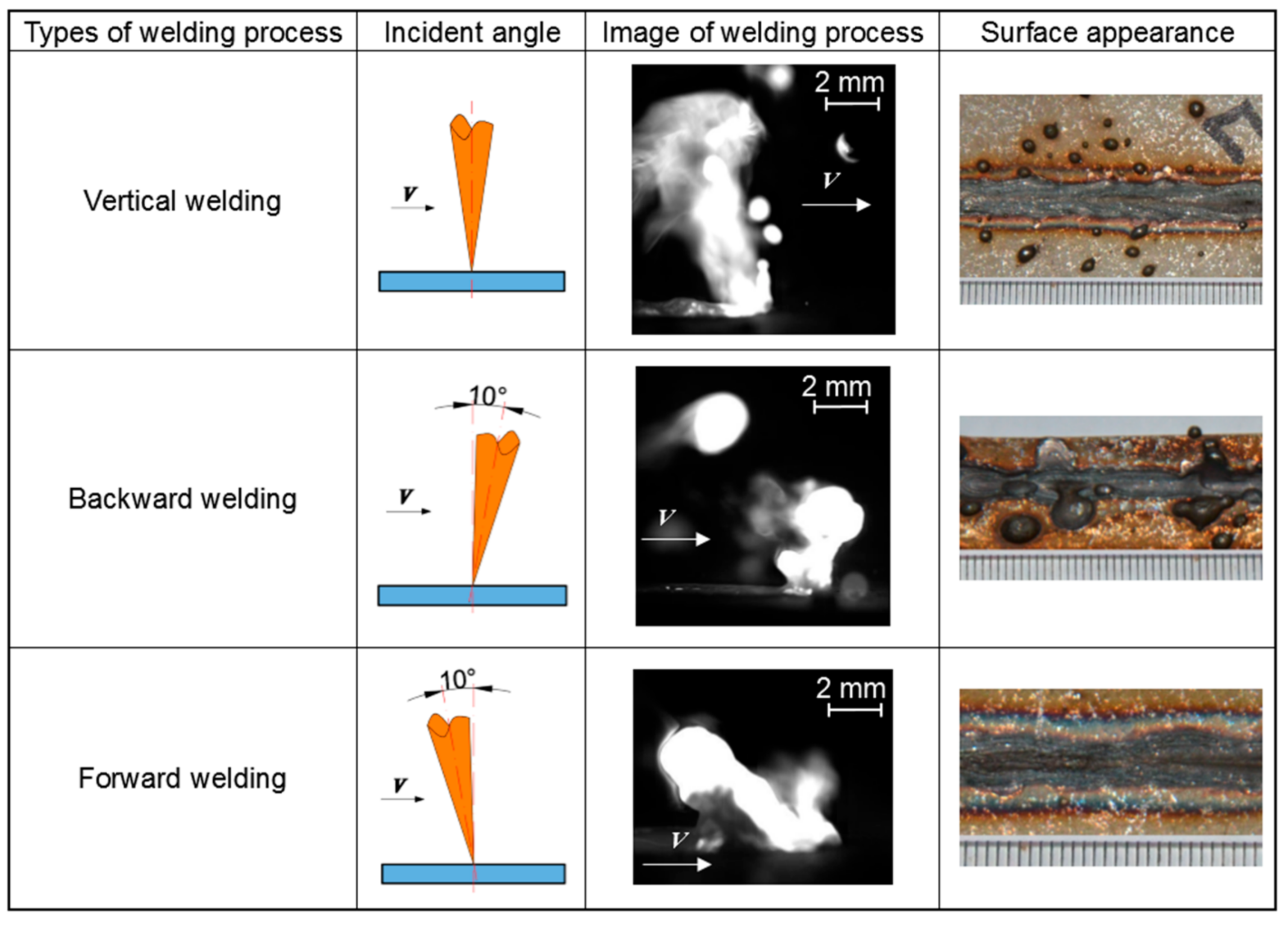
Figure 7 shows the effect of the incident angle of laser beam on the welding process and surface appearance. A large amount of vapor plume was ejected from the keyhole entrance; when the laser beam irradiated vertically, the spatters were generated and ejected with metal droplets. When the laser beam irradiated with an incident angle of 10 degrees backwards, a part of the melt column was stretched out of the melt pool along the front keyhole wall, and it was accompanied by the ejection of the vapor plume in the welding direction, and was then separated from the melt pool to form a big spatter. As a result, the weld width was narrow in a backward welding. When the laser beam irradiated with an incident angle of 10 degrees forwards, a part of the melt column was also stretched out of the melt pool along the rear keyhole wall, but it was accompanied by the ejection of the vapor plume in the opposite direction of welding. However, the melt column had been hauled back into the melt pool without the formation of spatters. Consequently, the surface appearance of the joint welded was good in a forward welding.
3.2.2. Suppression Mechanism of Spatters in a Forward Welding
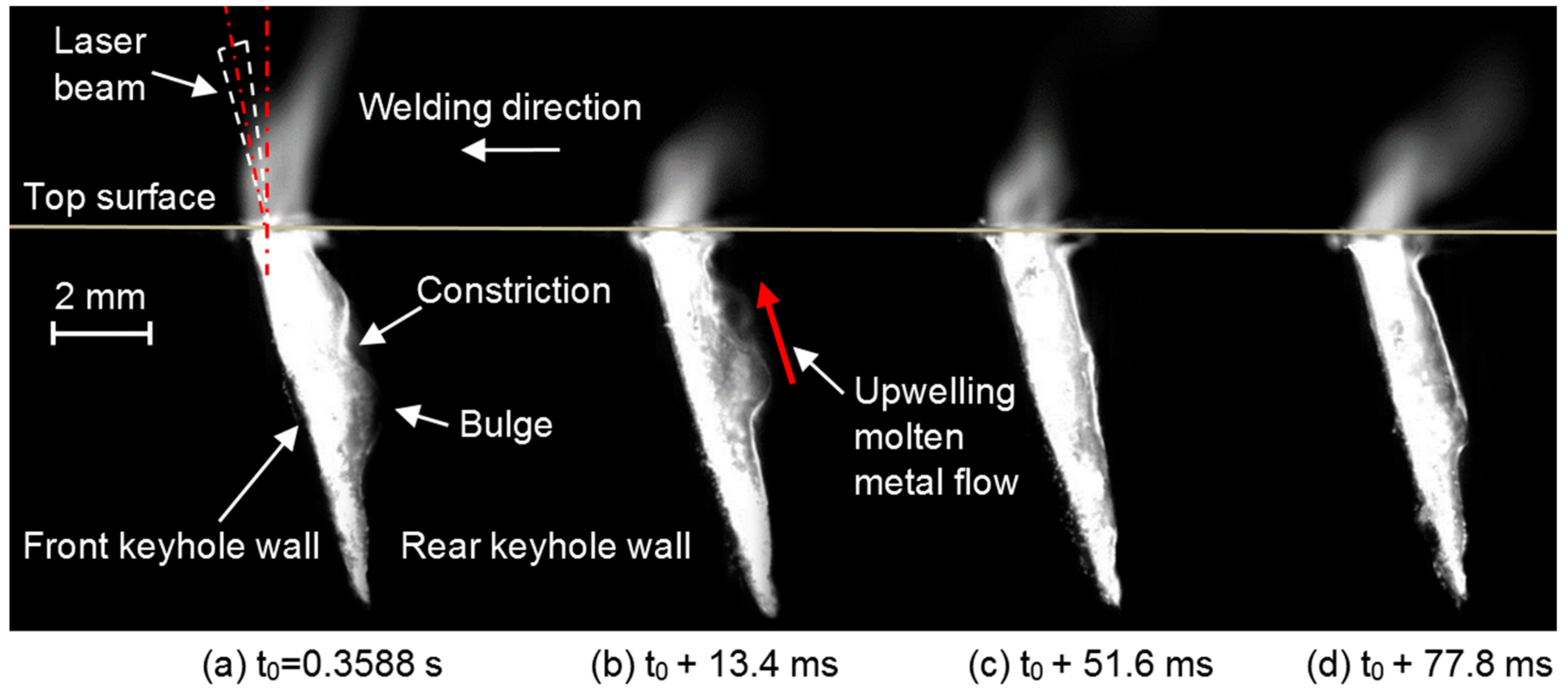
Figure 8 and Figure 9 show the images which were simultaneously captured for the keyhole and the vapor plume in the vertical and backward welding; the modified ‘sandwich’ method was applied. The keyhole front wall was almost vertical in the vertical welding, as shown in Figure 8. The keyhole front wall was inclined along the welding direction in the backward welding, as shown in Figure 9. A chain of bulges and constrictions were formed on the rear keyhole wall; it was accompanied with an urgently upwelling molten metal flow in the upward direction (illustrated by red arrows in Figure 8a and Figure 9b) [25]. Naturally, a swelling was formed behind the keyhole entrance with the accumulation of the upwelling melt at the rear keyhole wall (Figure 8b,e). However, the depth of the weld pool was shallow behind the keyhole entrance (Figure 8 and Figure 9). The vapor plume was ejected out of the keyhole entrance in the vertical upward direction or against the welding direction. Consequently, the spatter was derived from the upwelling melt, and generated by the burst of the vapor plume overcoming the lower surface tension with a shallow weld pool behind the keyhole entrance [21].
Figure 10 shows the images, which was simultaneously obtained for the keyhole and the vapor plume in the forward welding; the modified ‘sandwich’ method was applied. The keyhole front wall was inclined against the welding direction in the forward welding. There was not an evident chain of bulges and constrictions formed on the rear keyhole wall, which was accompanied with a gently upwelling molten metal flow in the upward direction (illustrated by red arrows in Figure 10a). The depth of the upper weld pool was deep behind the keyhole entrance (Figure 10). A small vapor plume was ejected out of the keyhole entrance against the welding direction. As a result, the upwelling melt flowed into the upper weld pool without the formation of spatter.
3.3. Effect of Welding Position on Formation of Root Sagging
3.3.1. Weld Appearance
Figure 11 shows the effect of welding positions on weld appearance. Welding could be placed in two positions, namely PA and PC, in accordance with EN287/ISO 6947 by American Society of Mechanical Engineering (ASME). A PA position referred to the case where the workpiece was placed horizontally in a flat position, and the laser beam irradiated the workpiece vertically. PC position refers to the case where the workpiece was placed vertically in the transverse position; the laser beam irradiated the workpiece horizontally. In the PA welding position, the weld was collapsed and sagged at the top surface and the bottom surface, respectively. The appearance of the weld seam was poor since the underfill and root sagging were formed. In the PC welding position, the appearance of the weld seam was good and there was no formation of underfill or root sagging.
3.3.2. Suppression Mechanism of Root Sagging in PC Welding Position
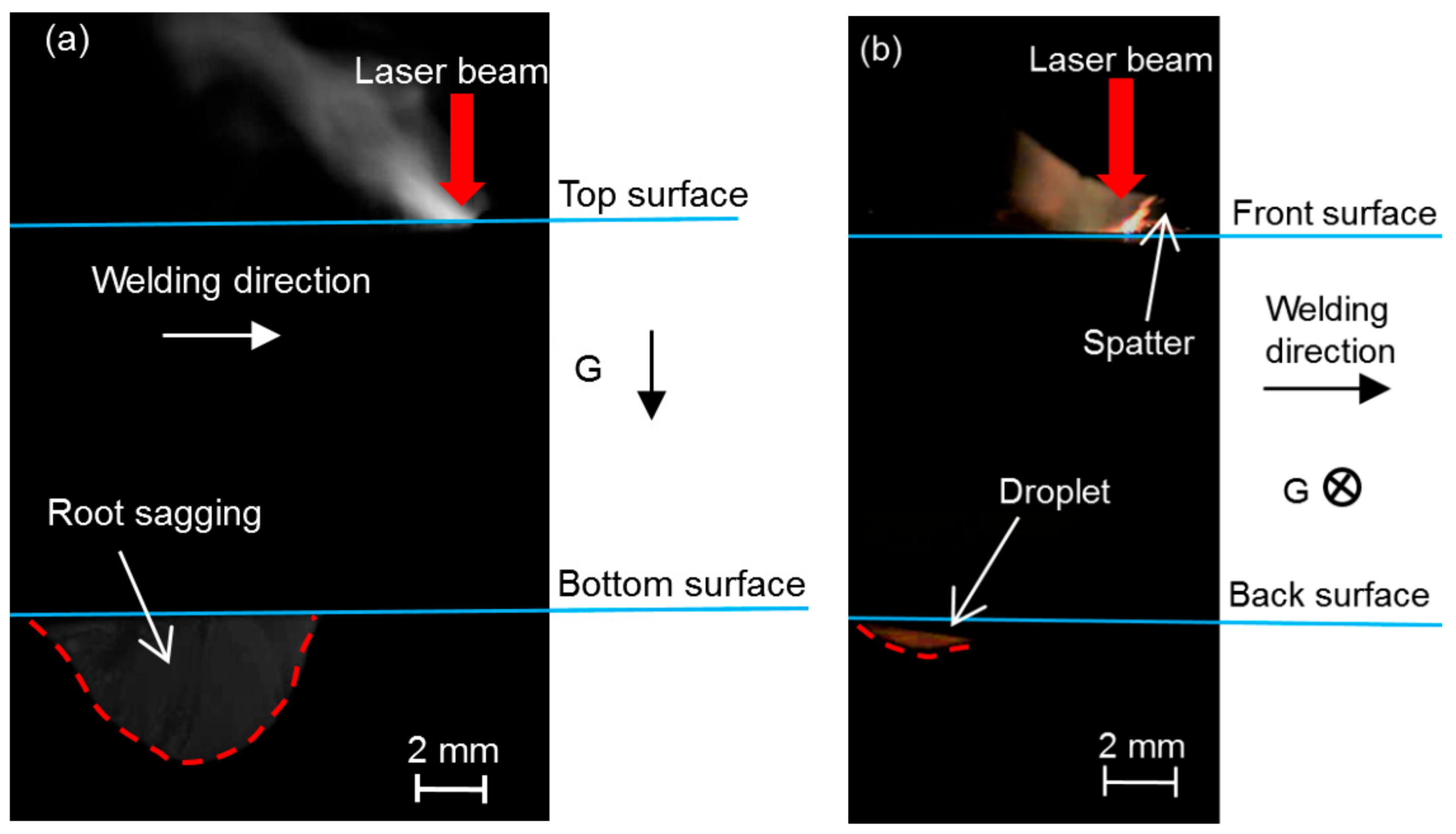
Figure 12 shows the images of the welding processes in PA and PC welding positions, respectively. With the PA welding position, the molten melt flowed downwards and then backwards to form a droplet at the bottom surface. As the welding continued, the droplet grew gradually with the accumulation of the molten melt at the bottom surface. Finally, the droplet solidified and attached to the bottom surface of the weld seam (Figure 12a). On the other hand, the downward flow of the molten melt caused the collapse of the weld pool at the top surface with no spatter or the melt column stretched out of the melt pool. However, there was less molten melt aggregating at the bottom surface, this formed a small droplet at the back surface in the PC welding position. The melt pool at the front surface was full with the formation of spatters and melt column stretched out (Figure 12b). The result indicated that, in the PA welding position, the gravity of the molten melt played an important role in the generation of underfill and root sagging. This is also a fundamental difference between the root sagging and the hump at the top surface [26,27].
4. Conclusions
Experiments with autogenous laser welding were performed on thick steel plates to explore the suppression mechanisms of poor weld appearance (nail-head-shaped weld, spatters, and root sagging). The followings were our findings from the experiments and discussions over the experimental results:
(1) The nail-head-shaped weld was suppressed by using a gas jet. When a gas jet was used, the keyhole entrance was large, and the melt flow around the keyhole entrance was stable. The molten metal at the rear of the keyhole flowed backwards fast enough that the Marangoni convection at the upper weld pool was suppressed. The welding depth was deeper than that without gas jet.
(2) Forward welding, wherein the laser beam irradiated with an incident angle of 10 degrees forwards, could be used to suppress spatters. In the forward welding, a part of the melt column was stretched out of the melt pool along the rear keyhole wall and it was hauled back without formation of spatter.
(3) Based on the modified ‘sandwich’ specimen, the longitudinal keyhole profile and molten pool were observed directly via a high-speed imaging system. In the forward welding, the upwelling molten metal flow on the rear keyhole wall was gentler than that in the vertical or backward welding, respectively. Furthermore, a deeper weld pool behind the keyhole and a weaker vapor plume were accompanied with a higher surface tension of the molten melt and a low friction force on the melt column, resulting in no spatter in the forward welding.
(4) Gravity affected the formation of underfill and root sagging significantly in the autogenous laser welding of thick plates. The PC welding position aligned gravity with the direction of the welding penetration, this was preferred to stabilize the welding process without an aggregation of the molten melt at the back surface. The root sagging and the hump at the top surface were formed in different ways.
Author Contributions
M.Z. and S.C. designed and performed the experiments, conducted results analysis, and wrote the manuscript. Y.Z. employed the high-speed imaging system and analyzed the results. G.C. instructed the experimental scheme and conducted results analysis. Z.B. reviewed the manuscript and conducted results analysis.
Funding
National Natural Science Foundation of China (no. 51605045, 51641502), the Natural Science Foundation of Hunan Province of China (no. 2018JJ2437, 2015JJ3003).
Acknowledgments
The authors are grateful to the financial support from the National Natural Science Foundation of China (no. 51605045, 51641502), the Natural Science Foundation of Hunan Province of China (no. 2018JJ2437, 2015JJ3003).
Conflicts of Interest
The authors declare no conflict of interest.
References
- Vollertsen, F.; Thomy, C. Welding with fiber lasers from 200 to 17000 W. In Proceedings of the Laser 24th International Congress on Applications of Lasers and Electro-Optics, Miami, FL, USA, 1 January 2005; Laser Institute of America: Orlando, FL, USA, 2005. [Google Scholar]
- Fomin, V.; Gapontsev, V.; Shcherbakov, E.; Abramov, A.; Ferin, A.; Mochalov, D. 100 kW CW fiber laser for industrial applications. In Proceedings of the 2014 International Conference Laser Optics, Burbach, Germany, 28 August 2014; IEEE: St. Petersburg, Russia, 2014. [Google Scholar]
- Guo, W.; Crowther, D.; Francis, J.A.; Thompson, A.; Liu, Z.; Li, L. Microstructure and mechanical properties of laser welded S960 high strength steel. Mater. Des. 2015, 85, 534–548. [Google Scholar] [CrossRef]
- Zhang, L.J.; Bai, Q.L.; Ning, J.; Wang, A.; Yang, N.J.; Yin, X.Q.; Zhang, J.X. A comparative study on the microstructure and properties of copper joint between MIG welding and laser-MIG hybrid welding. Mater. Des. 2016, 10, 35–50. [Google Scholar] [CrossRef]
- Katayama, S.; Kawahito, Y.; Mizutani, M. Elucidation of laser welding phenomena and factors affecting weld penetration and welding defects. Phys. Procedia 2010, 5, 9–17. [Google Scholar] [CrossRef]
- Li, S.; Xu, W.; Su, F.; Deng, H.; Deng, Z. Influence of CO2 shielding gas on high power fiber laser welding performance. Metals 2018, 8, 449. [Google Scholar] [CrossRef]
- Popescu, A.; Delval, C.; Leparoux, M. Control of porosity and spatter in laser welding of thick AlMg5 parts using high-speed imaging and optical microscopy. Metals 2017, 7, 452. [Google Scholar] [CrossRef]
- Nishimoto, K.; Woo, I.; Ogita, T.; Shirai, M. The factors affecting HAZ crack susceptibility in the laser weld: Study on weldability of cast alloy 718 (report 4). Q. J. Jpn. Weld. Soc. 2001, 19, 308–316. [Google Scholar] [CrossRef]
- Rai, R.; Palmer, T.A.; Elmer, J.W.; Debroy, T. Heat transfer and fluid flow during electron beam welding of 304L stainless steel alloy. Weld. J. 2009, 88, 54–61. [Google Scholar]
- Zacharia, T.; David, S.A.; Vitek, J.M.; Debroy, T. Weld pool development during GTA and laser beam welding of type 304 stainless steel; Part II-experimental correlation. Weld. J. 1989, 68, 510–519. [Google Scholar]
- Bachmann, M.; Avilov, V.; Gumenyuk, A.; Rethmeier, M. About the influence of a steady magnetic field on weld pool dynamics in partial penetration high power laser beam welding of thick aluminium parts. Int. J. Heat Mass Transf. 2013, 60, 309–321. [Google Scholar] [CrossRef]
- Kaplan, A.F.H.; Powell, J. Spatter in laser welding. J. Laser Appl. 2011, 23, 3337–3344. [Google Scholar] [CrossRef]
- Semak, V.; Matsunawa, A. The role of recoil pressure in energy balance during laser materials processing. J. Phys. D Appl. Phys. 1997, 30, 2541–2552. [Google Scholar] [CrossRef]
- Blecher, J.J.; Palmer, T.A.; DebRoy, T. Mitigation of root defect in laser and hybrid laser-arc welding. Weld. J. 2015, 94, 73–82. [Google Scholar]
- Guo, W.; Liu, Q.; Francis, J.A.; Crowther, D.; Thompson, A.; Liu, Z. Comparison of laser welds in thick section S700 high-strength steel manufactured in flat (1G) and horizontal (2G) positions. CIRP Ann.-Manuf. Technol. 2015, 64, 197–200. [Google Scholar] [CrossRef]
- Eriksson, I.; Powell, J.; Kaplan, A. Measurements of fluid flow on keyhole front during laser welding. Sci. Technol. Weld. Join. 2011, 16, 636–641. [Google Scholar] [CrossRef] [Green Version]
- Kaplan, A.F. Local flashing events at the keyhole front in laser welding. Opt. Lasers Eng. 2015, 68, 35–41. [Google Scholar] [CrossRef]
- Kaplan, A.F. Fresnel absorption of 1 μm- and 10 μm-laser beams at the keyhole wall during laser beam welding: Comparison between smooth and wavy surfaces. Appl. Surf. Sci. 2012, 258, 3354–3363. [Google Scholar] [CrossRef]
- Haug, P.; Rominger, V.; Speker, N.; Weber, R.; Graf, T.; Weigl, M.; Schmidt, M. Influence of laser wavelength on melt bath dynamics and resulting seam quality at welding of thick plates. Phys. Procedia 2013, 41, 49–58. [Google Scholar] [CrossRef]
- Zhang, M.J.; Zhang, Z.; Tang, K.; Mao, C.; Hu, Y.L.; Chen, G.Y. Analysis of mechanisms of underfill in full penetration laser welding of thick stainless steel with a 10 kw fiber laser. Opt. Laser Technol. 2018, 98, 97–105. [Google Scholar] [CrossRef]
- Zhang, M.J.; Chen, G.Y.; Zhou, Y.; Li, S.C.; Deng, H. Observation of spatter formation mechanisms in high-power fiber laser welding of thick plate. Appl. Surf. Sci. 2013, 280, 868–875. [Google Scholar] [CrossRef]
- Kamimuki, K.; Inoue, T.; Yasuda, K.; Muro, M.; Nakabayashi, T.; Matsunawa, A. Prevention of welding defect by side gas flow and its monitoring method in continuous wave Nd: YAG laser welding. J. Laser Appl. 2002, 14, 136–145. [Google Scholar] [CrossRef]
- Fabbro, R.; Slimani, S.; Doudet, I.; Coste, F.; Briand, F. Experimental study of the dynamical coupling between the induced vapour plume and the melt pool for Nd Yag CW laser welding. J. Phys. D Appl. Phys. 2006, 39, 394. [Google Scholar] [CrossRef]
- Semak, V.V.; Hopkins, J.A.; Mccay, M.H.; Mccay, T.D. Melt pool dynamics during laser welding. J. Phys. D Appl. Phys. 1995, 28, 2443–2450. [Google Scholar] [CrossRef]
- Katayama, S.; Kawahito, Y. Elucidation of phenomena in high power fiber laser welding and development of prevention procedures of welding defects. In Proceedings of the SPIE LASE: Lasers and Applications in Science and Engineering, San Jose, CA, USA, 19 February 2009; Elsevier: Osaka, Japan, 2009. [Google Scholar]
- Ilar, T.; Eriksson, I.; Powell, J.; Kaplan, A. Root humping in laser welding—an investigation based on high speed imaging. Phys. Procedia 2012, 39, 27–32. [Google Scholar] [CrossRef]
- Berger, P.; Hügel, H.; Hess, A.; Weber, R.; Graf, T. Understanding of humping based on conservation of volume flow. Phys. Procedia 2011, 12, 232–240. [Google Scholar] [CrossRef]
Figure 1.
Experimental setup.

Figure 2.
Schematic of the laser welding setup for: (a) bead-on-plate welding, and (b) welding with modified ‘sandwich’ sample.
Figure 2.
Schematic of the laser welding setup for: (a) bead-on-plate welding, and (b) welding with modified ‘sandwich’ sample.

Figure 3.
Effect of the gas jet on the weld appearance (p = 10 kW, v = 0.9 m/min, Δ = −5 mm, q = 10 L/min).
Figure 3.
Effect of the gas jet on the weld appearance (p = 10 kW, v = 0.9 m/min, Δ = −5 mm, q = 10 L/min).

Figure 4.
Images of the keyhole entrance and surface weld pool dynamics without a gas jet (p = 10 kW, v = 0.9 m/min, Δ = −5 mm, q = 10 L/min).
Figure 4.
Images of the keyhole entrance and surface weld pool dynamics without a gas jet (p = 10 kW, v = 0.9 m/min, Δ = −5 mm, q = 10 L/min).

Figure 5.
Images of the keyhole entrance and surface weld pool dynamics with a front gas jet (p = 10 kW, v = 0.9 m/min, Δ = −5 mm, q = 10 L/min).
Figure 5.
Images of the keyhole entrance and surface weld pool dynamics with a front gas jet (p = 10 kW, v = 0.9 m/min, Δ = −5 mm, q = 10 L/min).
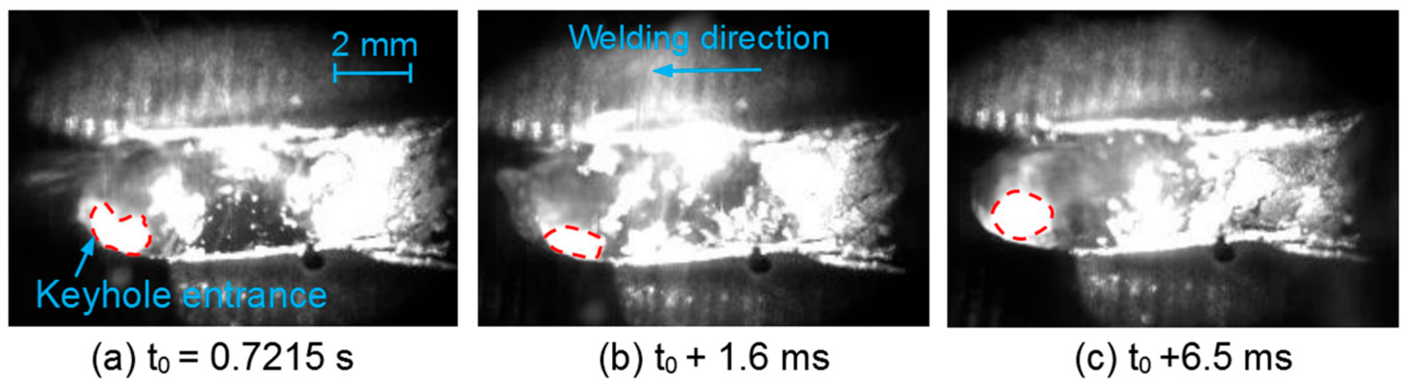
Figure 6.
Images of the keyhole entrance and surface weld pool dynamics with a rear gas jet (p = 10 kW, v = 0.9 m/min, Δ = −5 mm, q = 10 L/min).
Figure 6.
Images of the keyhole entrance and surface weld pool dynamics with a rear gas jet (p = 10 kW, v = 0.9 m/min, Δ = −5 mm, q = 10 L/min).

Figure 7.
Effect of the incident angle on the weld pool and surface appearance (p = 10 kW, v = 1.8 m/min, Δ = +10 mm, q = 30 L/min).
Figure 7.
Effect of the incident angle on the weld pool and surface appearance (p = 10 kW, v = 1.8 m/min, Δ = +10 mm, q = 30 L/min).

Figure 8.
Images of the longitudinal keyhole and vapor plume in the vertical welding (p = 10 kW, v = 1.8 m/min, Δ = +10 mm).
Figure 8.
Images of the longitudinal keyhole and vapor plume in the vertical welding (p = 10 kW, v = 1.8 m/min, Δ = +10 mm).
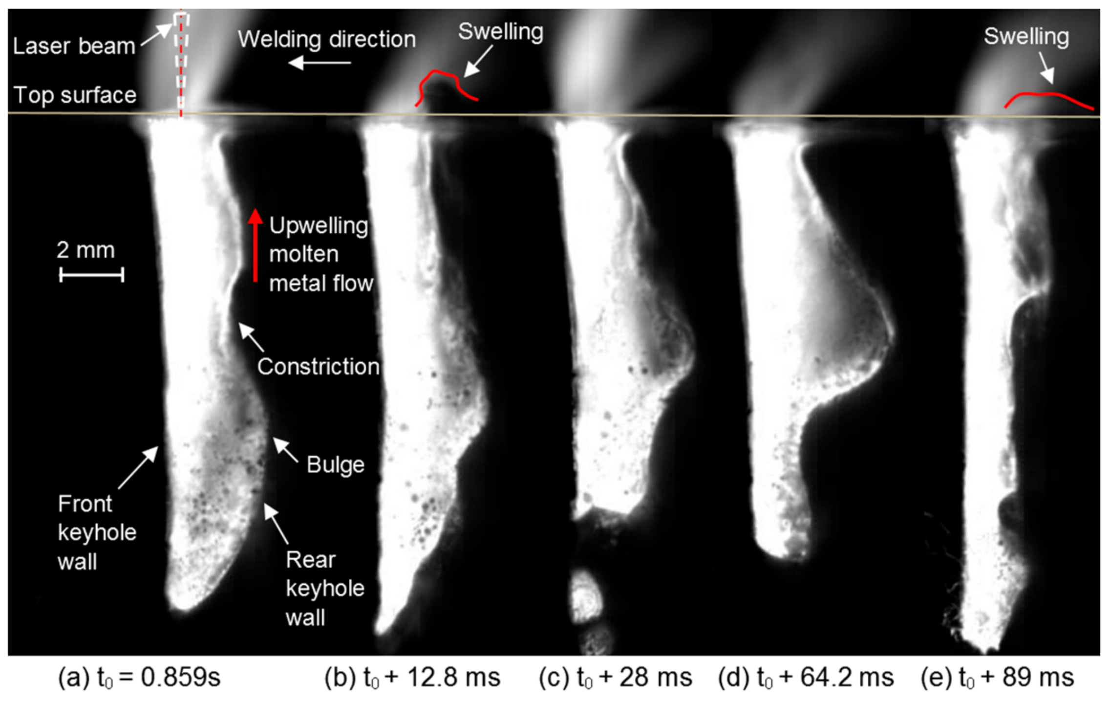
Figure 9.
Images of the longitudinal keyhole and vapor plume in the backward welding (p = 10 kW, v = 1.8 m/min, Δ = +10 mm).
Figure 9.
Images of the longitudinal keyhole and vapor plume in the backward welding (p = 10 kW, v = 1.8 m/min, Δ = +10 mm).

Figure 10.
Images of the longitudinal keyhole and vapor plume in the forward welding (p = 10 kW, v = 1.8 m/min, Δ = +10 mm).
Figure 10.
Images of the longitudinal keyhole and vapor plume in the forward welding (p = 10 kW, v = 1.8 m/min, Δ = +10 mm).
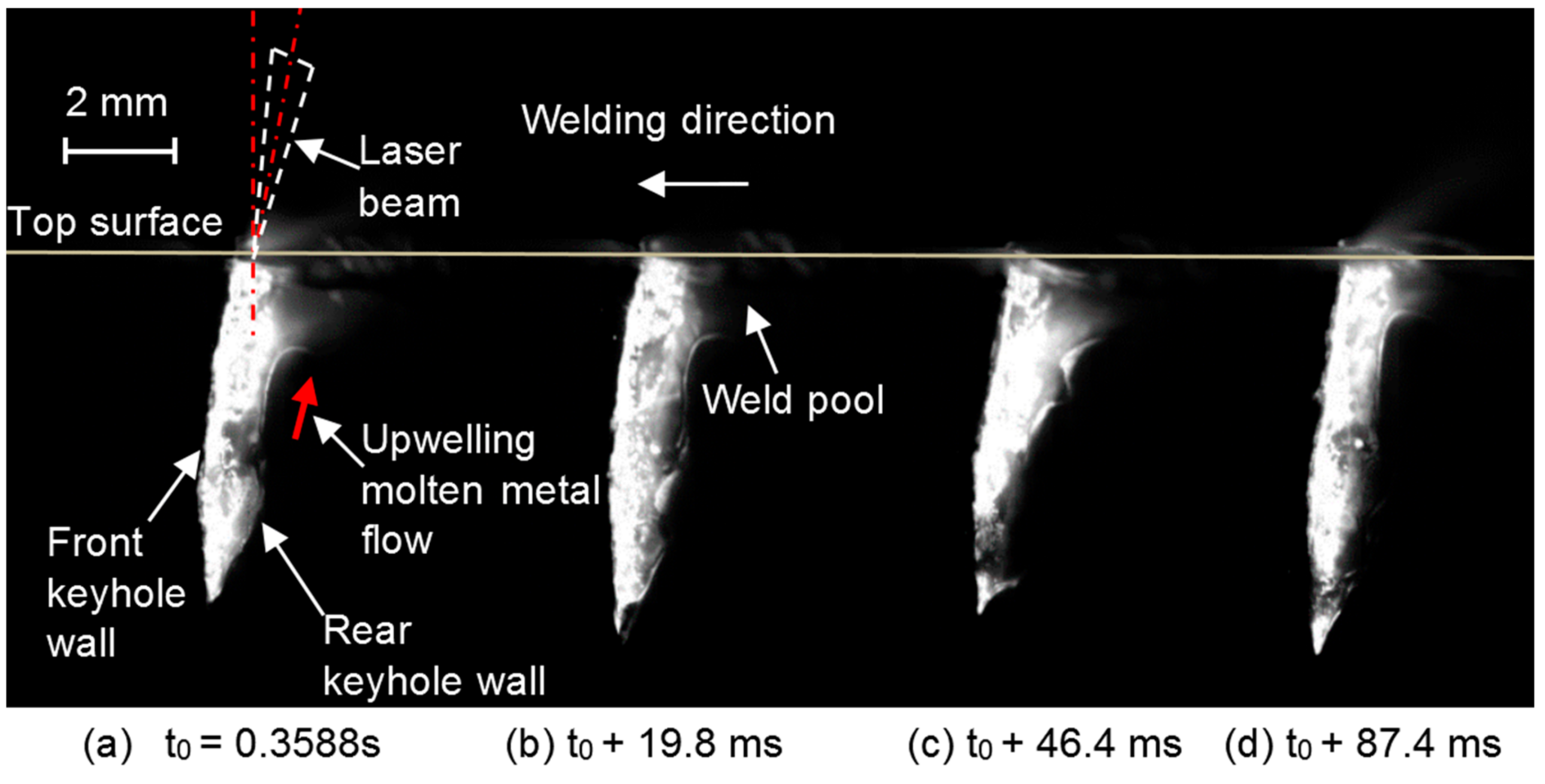
Figure 11.
Effect of welding positions on the weld appearance (p = 10 kW, v = 1.2 m/min, Δ = +10 mm, q = 20 L/min).
Figure 11.
Effect of welding positions on the weld appearance (p = 10 kW, v = 1.2 m/min, Δ = +10 mm, q = 20 L/min).
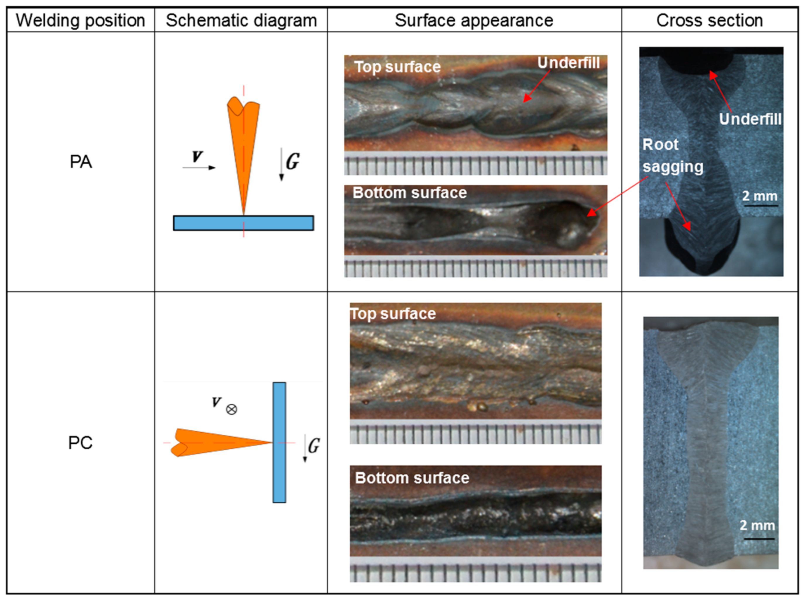
Figure 12.
Images of the welding processes with different welding positions: (a) PA position, and (b) PC position (p = 10 kW, v = 0.9 m/min, Δ = +10 mm, q = 20 L/min).
Figure 12.
Images of the welding processes with different welding positions: (a) PA position, and (b) PC position (p = 10 kW, v = 0.9 m/min, Δ = +10 mm, q = 20 L/min).


Table 1.
Welding parameters with different penetration regimes.
| Weld No. | Weld Sample | Weld Speed (v) (m/min−1) | Defocus (Δ) (mm) | Shielding Gas Flow (q) (L/min) (N2) | Gas Jet (Ar) | Angle of Incidence (°) | Welding Position |
|---|---|---|---|---|---|---|---|
| 1 | Bead-on-plate | 0.9 | −5 | 10 | No | No | PA |
| 2 | Bead-on-plate | 0.9 | −5 | 10 | Front gas jet | No | PA |
| 3 | Bead-on-plate | 0.9 | −5 | 10 | Rear gas jet | No | PA |
| 4 | Bead-on-plate | 1.8 | +10 | 30 | No | No | PA |
| 5 | Bead-on-plate | 1.8 | +10 | 30 | No | +10 | PA |
| 6 | Bead-on-plate | 1.8 | +10 | 30 | No | −10 | PA |
| 7 | Modified ‘sandwich’ | 1.8 | +10 | 0 | No | No | PA |
| 8 | Modified ‘sandwich’ | 1.8 | +10 | 0 | No | +10 | PA |
| 9 | Modified ‘sandwich’ | 1.8 | +10 | 0 | No | −10 | PA |
| 10 | Bead-on-plate | 1.2 | +10 | 20 | No | No | PA |
| 11 | Bead-on-plate | 1.2 | +10 | 20 | No | No | PC |
| 12 | Bead-on-plate | 0.9 | +10 | 20 | No | No | PA |
| 13 | Bead-on-plate | 0.9 | +10 | 20 | No | No | PC |
PA: Horizontal welding in flat position, PC: Transverse position.
© 2018 by the authors. Licensee MDPI, Basel, Switzerland. This article is an open access article distributed under the terms and conditions of the Creative Commons Attribution (CC BY) license (http://creativecommons.org/licenses/by/4.0/).
Share and Cite
MDPI and ACS Style
Zhang, M.; Chen, S.; Zhang, Y.; Chen, G.; Bi, Z. Mechanisms for Improvement of Weld Appearance in Autogenous Fiber Laser Welding of Thick Stainless Steels. Metals 2018, 8, 625. https://doi.org/10.3390/met8080625
AMA Style
Zhang M, Chen S, Zhang Y, Chen G, Bi Z. Mechanisms for Improvement of Weld Appearance in Autogenous Fiber Laser Welding of Thick Stainless Steels. Metals. 2018; 8(8):625. https://doi.org/10.3390/met8080625
Chicago/Turabian StyleZhang, Mingjun, Shun Chen, Yingzhe Zhang, Genyu Chen, and Zhuming Bi. 2018. "Mechanisms for Improvement of Weld Appearance in Autogenous Fiber Laser Welding of Thick Stainless Steels" Metals 8, no. 8: 625. https://doi.org/10.3390/met8080625
Note that from the first issue of 2016, this journal uses article numbers instead of page numbers. See further details here.