Thermal Mechanical Processing of Press and Sinter Al-Cu-Mg-Sn-(AlN) Metal Matrix Composite Materials

Abstract
:1. Introduction
2. Materials and Methods
3. Results
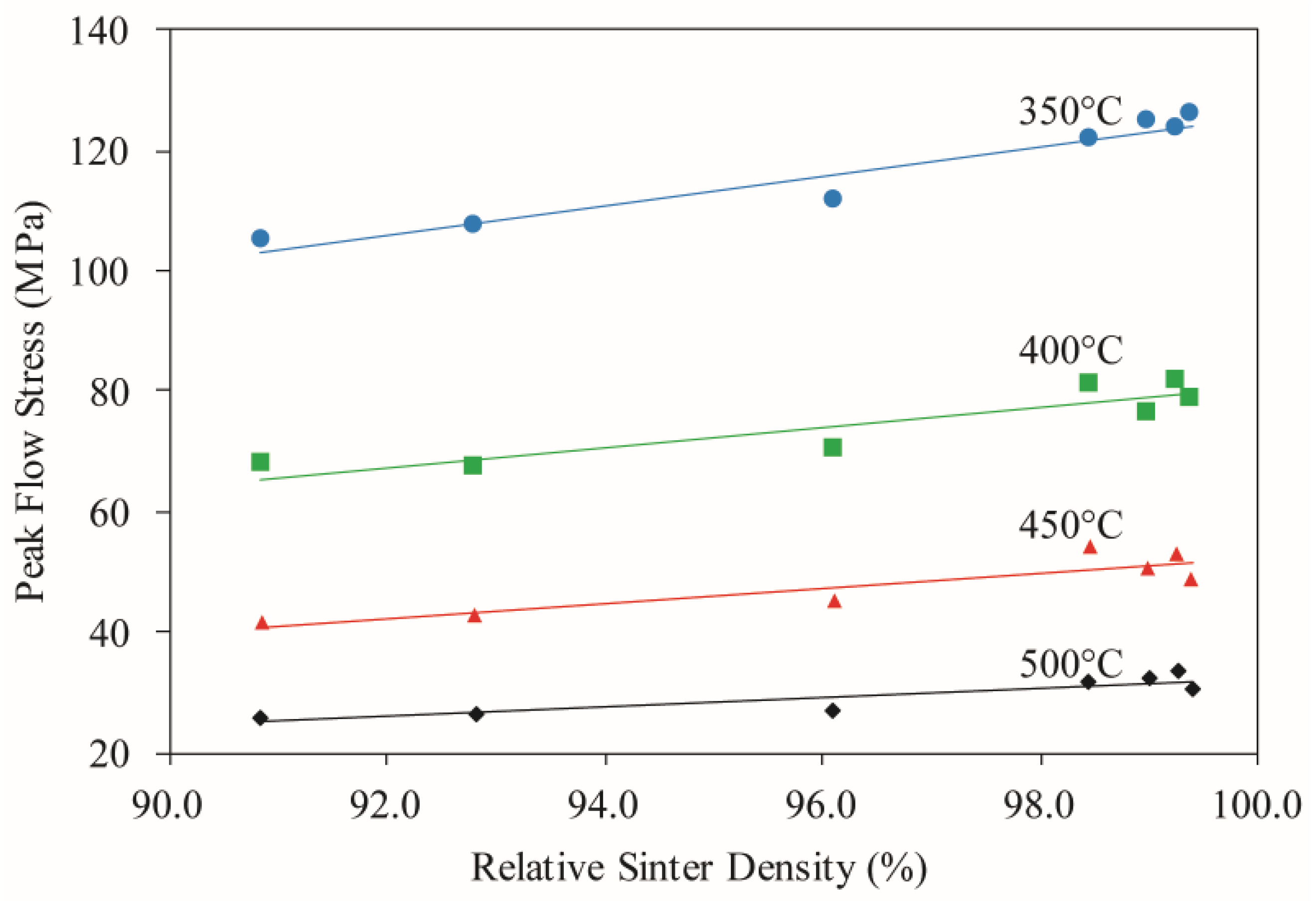
3.1. Densification
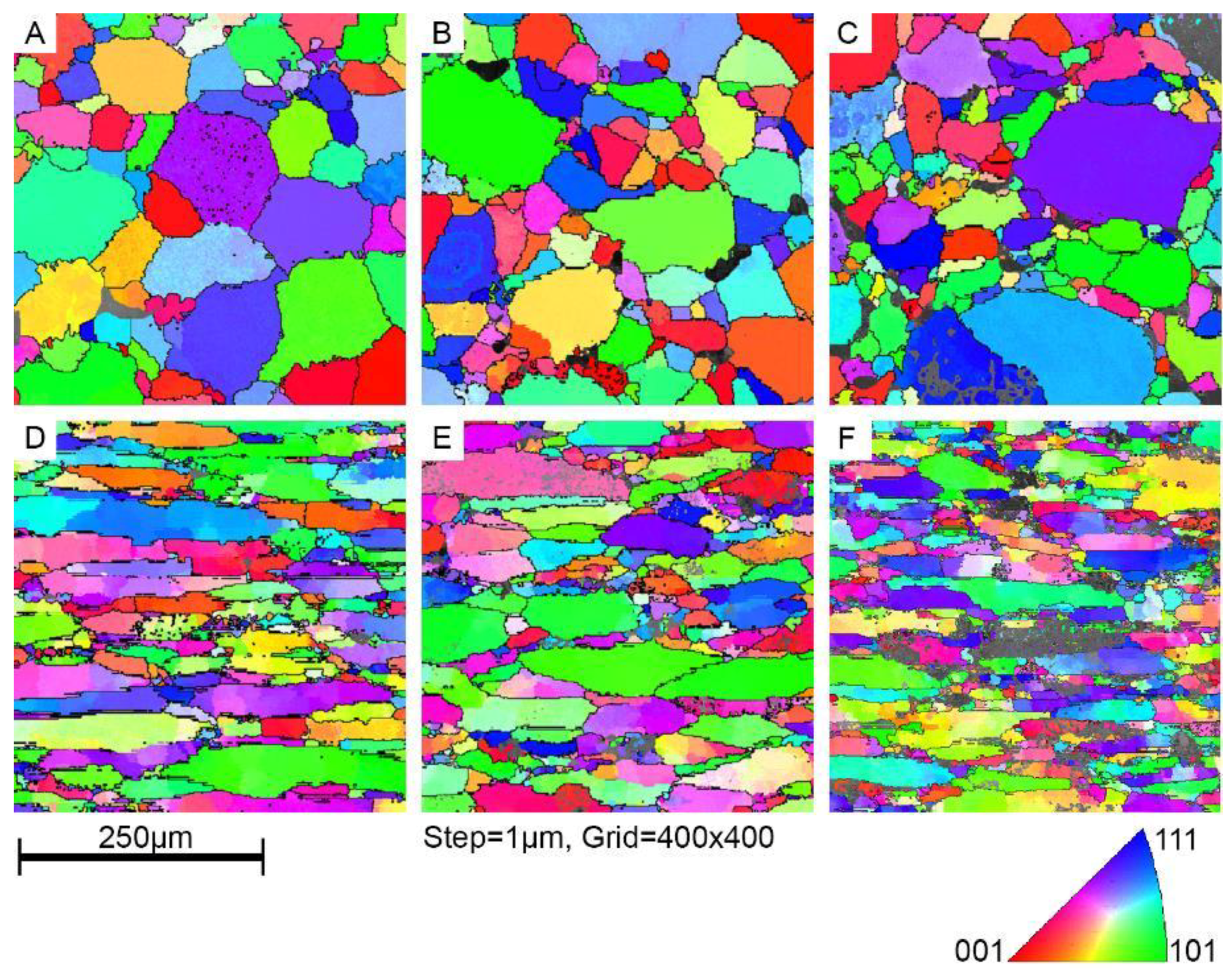
3.2. Microstructural Transitions
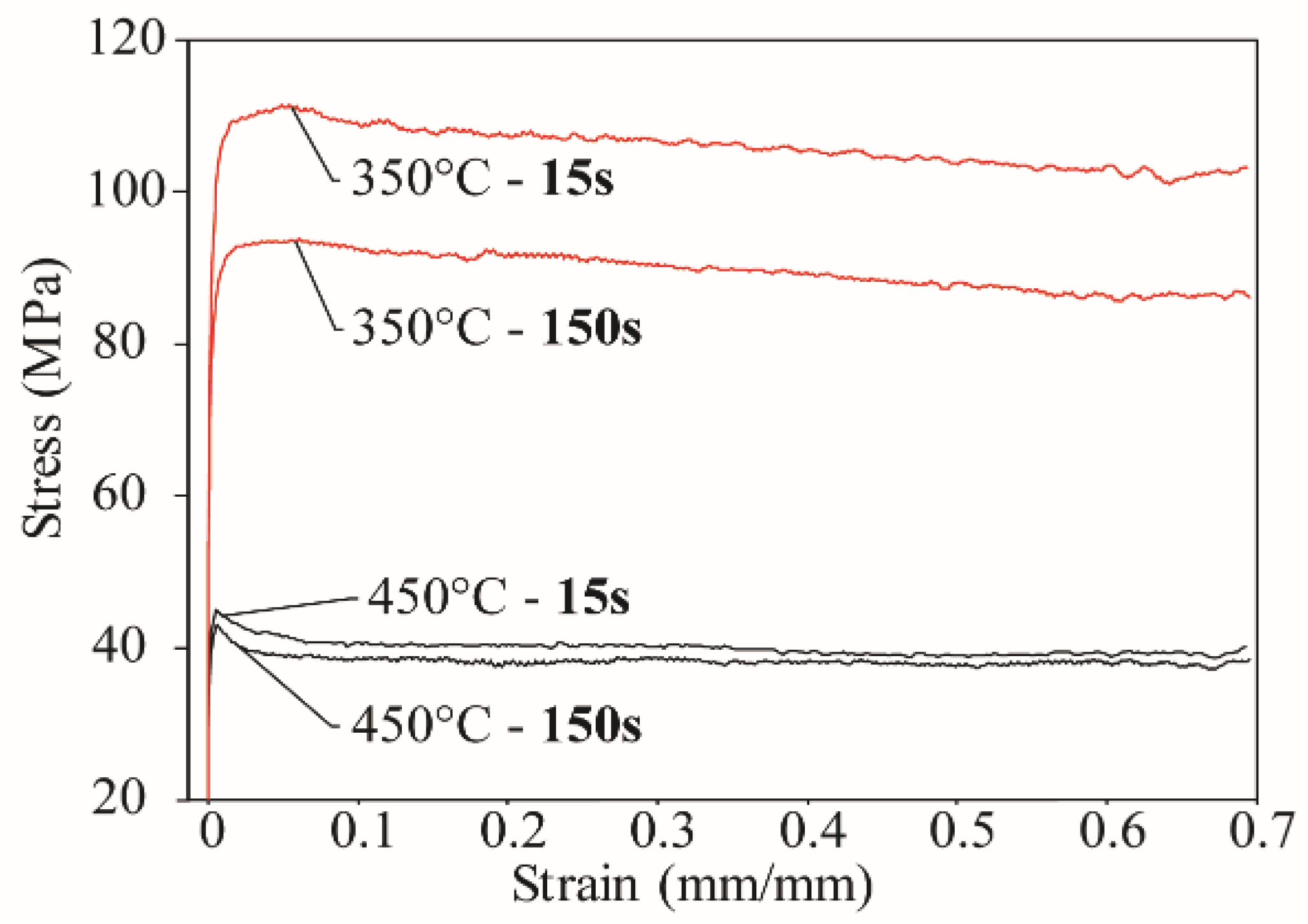
3.3. Flow Curves
4. Discussion
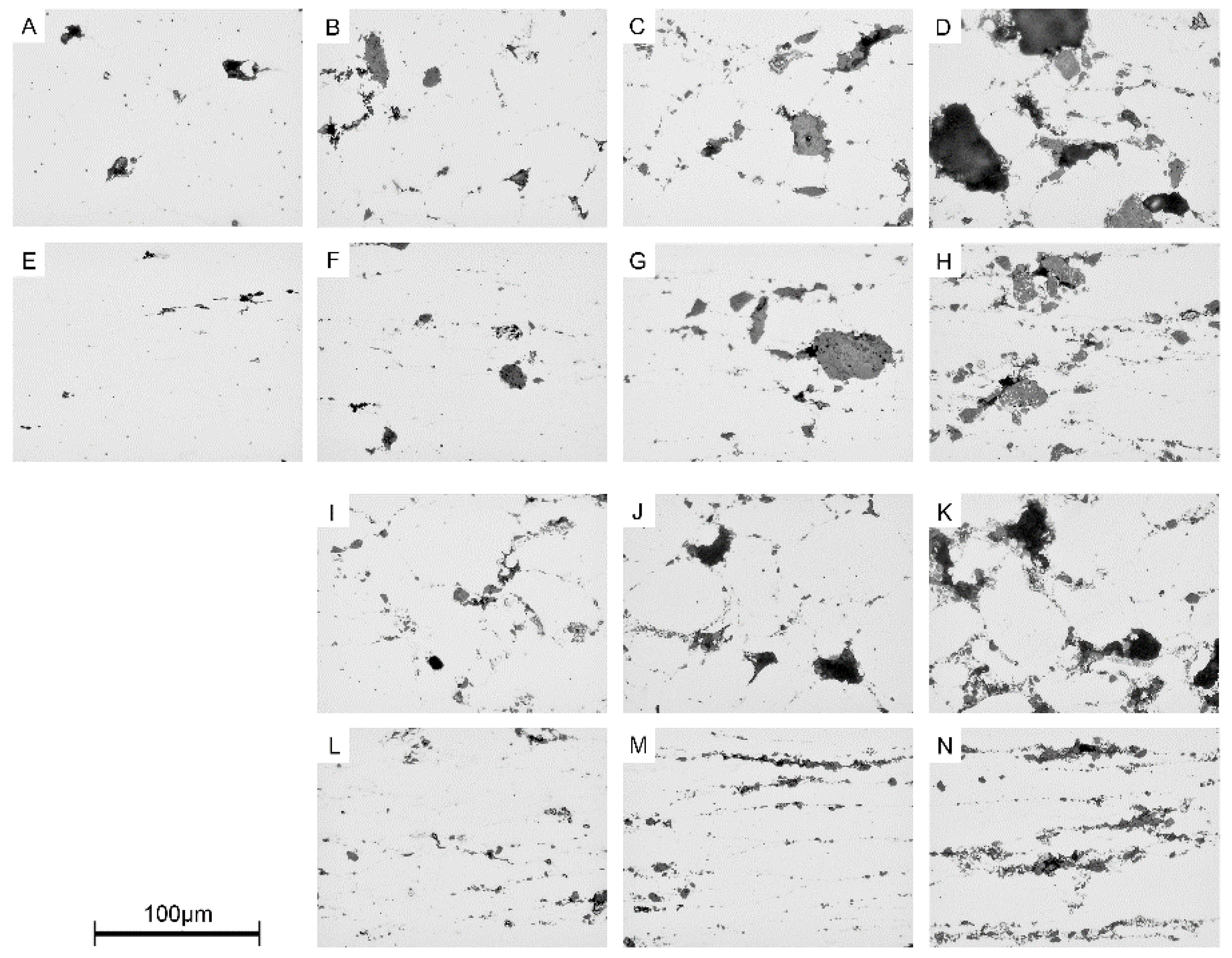
4.1. Porosity
4.2. Hot Ductility
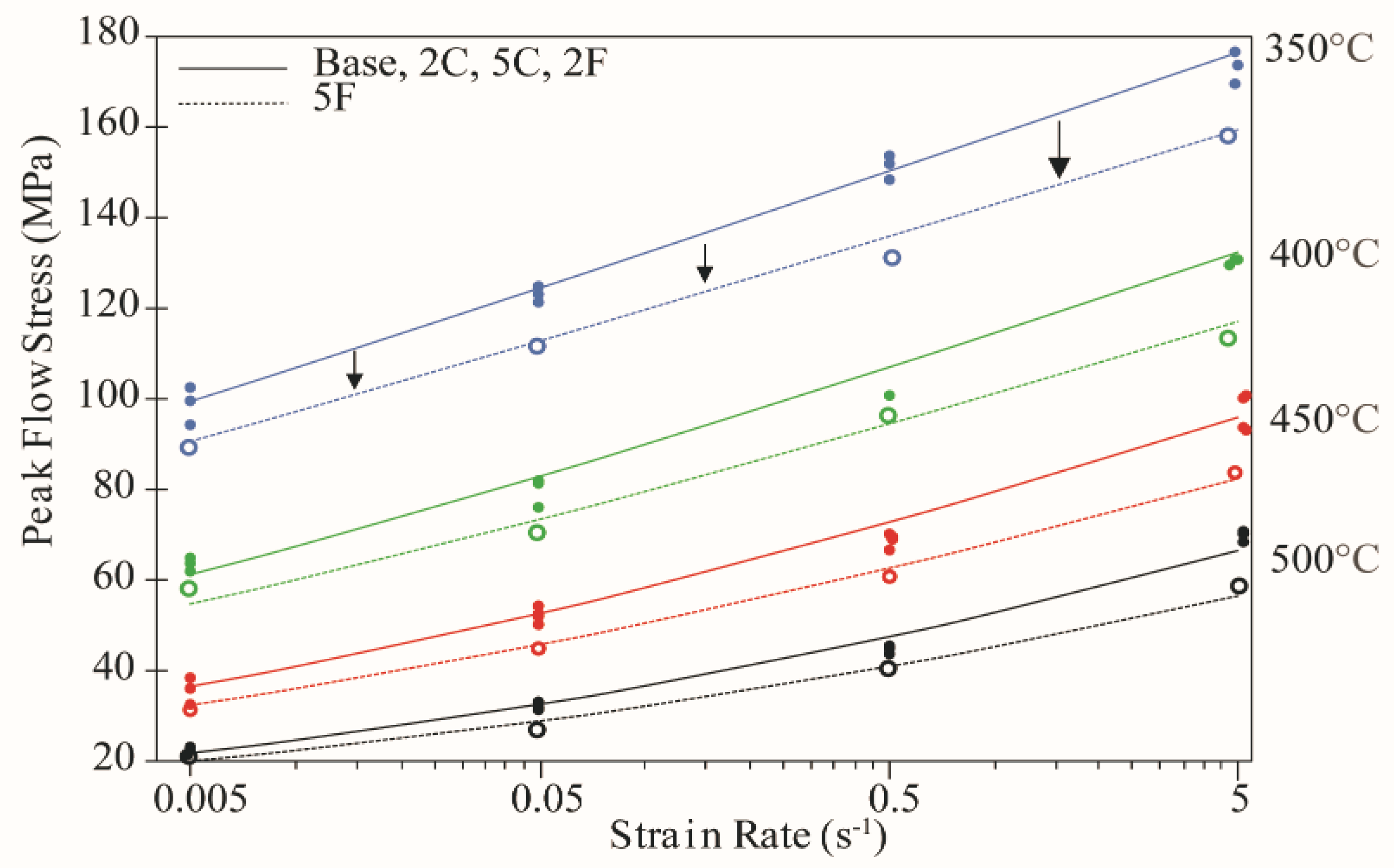
4.3. Flow Behavior
4.4. Constituent Analysis
5. Conclusions
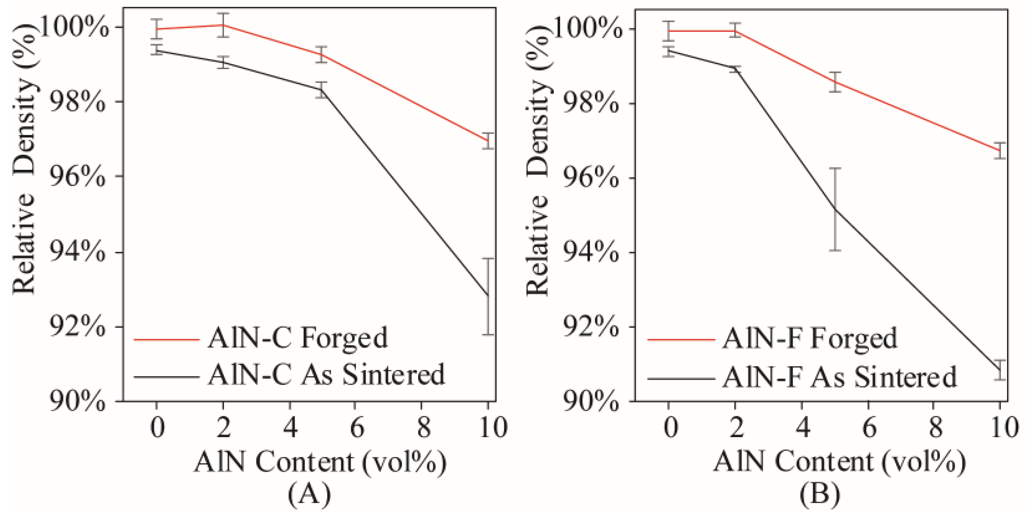
- The density of all materials invariably increased through TMP. However, temperature and strain rate did not influence final density values significantly. Samples that were sintered to near-theoretical density (>99.0%), including Base, 2C, and 2F alloys, were forged to essentially full density (>99.9%). Samples with an inferior sintered density did not reach their respective full density values.
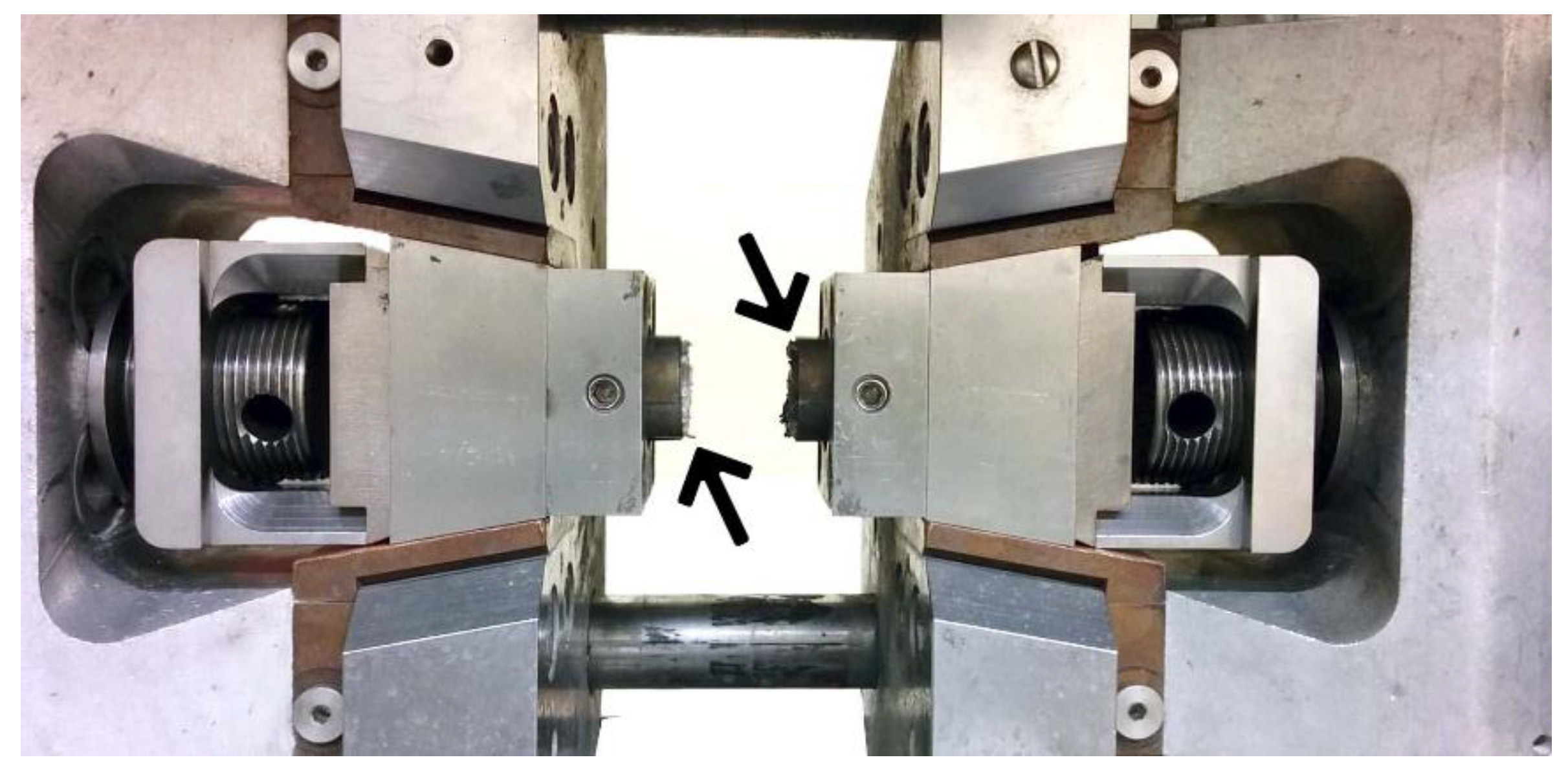
- Samples deformed at 500 °C were susceptible to cracking. Deformation facilitated in-situ heating beyond the targeted temperature under select circumstances that led to crack growth along prior particle boundaries. The lower sintered density of MMC 5F also appeared to be influential.
- Static and dynamic precipitation were exhibited throughout the deformation conditions considered. The effects of DPN were evident below the solvus, especially at the lowest deformation temperature. Temperatures of 450 °C and higher exhibited evidence of precipitate dissolution, encouraging lower flow stresses.
- The implementation of isothermal holds confirmed the occurrence of precipitation events. Increased isothermal hold time allowed for precipitate coarsening and an associate reduction in flow stress. At 450 °C, near-equilibrium flow stresses were approached within 15 s. At 350 °C, slower kinetics were apparent and softening occurred with 150 s isothermal hold prior to deformation.
- Additions of AlN that negatively impacted sintered density also decreased flow stress. This effect was most acute when AlN-F additions were employed.
- Zener-Hollomon analyses using a sinh approach enabled the peak flow stress characteristics of BASE, 2C, 5C, 2F, and 5F systems to be mapped. The results were effectively identical for all systems except the 5F formulation wherein a clear difference emerged.
Author Contributions
Funding
Acknowledgments
Conflicts of Interest
References
- Kim, Y.W.; Griffith, W.M.; Froes, F.H. Surface Oxides in P/M Aluminum-Alloys. J. Met. 1985, 37, 27–33. [Google Scholar] [CrossRef]
- Schaffer, G.B.; Sercombe, T.B.; Lumley, R.N. Liquid phase sintering of aluminium alloys. Mater. Chem. Phys. 2001, 67, 85–91. [Google Scholar] [CrossRef]
- Xie, G.; Ohashi, O.; Song, M.; Mitsuishi, K.; Yasuda, H.; Furuya, K.; Noda, T. Electron microscopic observation of interfaces of aluminium powder compacts prepared by spark plasma sintering. J. Electron. Microsc. 2002, 51, S149–S153. [Google Scholar] [CrossRef]
- Yi, J.Z.; Gao, Y.X.; Lee, P.D.; Flower, H.M.; Lindley, T.C. Scatter in fatigue life due to effects of porosity in cast A356-T6 aluminum-silicon alloys. Metall. Mater. Trans. A 2003, 34, 1879–1890. [Google Scholar] [CrossRef]
- James, W.B. Powder Forging. Rev. Part. Mater. 1994, 2, 173–214. [Google Scholar]
- Dashwood, R.; Schaffer, G. Powder forging of a sintered Al–3.8Cu–1Mg–0.8Si–0.1Sn alloy. Mater. Sci. Eng. A 2002, 323, 206–212. [Google Scholar] [CrossRef]
- Park, J.-O.; Kim, K.-J.; Kang, D.-Y.; Lee, Y.; Kim, Y.-H. An experimental study on the optimization of powder forging process parameters for an aluminum-alloy piston. J. Mater. Process. Technol. 2001, 113, 486–492. [Google Scholar] [CrossRef]
- Asgharzadeh, H.; Simchi, A.; Kim, H.S. Dynamic restoration and microstructural evolution during hot deformation of a P/M Al6063 alloy. Mater. Sci. Eng. A 2012, 542, 56–63. [Google Scholar] [CrossRef]
- Mosher, W.G.E.; Kipouros, G.J.; Caley, W.F.; Donaldson, I.W.; Bishop, D.P. On hot deformation of aluminium-silicon powder metallurgy alloys. Powder Metall. 2011, 54, 366–375. [Google Scholar] [CrossRef]
- Bose, A.; Eisen, W.B. Hot Consolidation of Powders & Particulates; Metal Powder Industries Federation: Princeton, NJ, USA, 2003; ISBN 1878954490. [Google Scholar]
- Committee, A.I.H. ASM Handbook, Volume 07—Powder Metal Technologies and Applications; ASM International: Materials Park, OH, USA, 1998; ISBN 978-0-87170-387-3. [Google Scholar]
- Abdel-Rahman, M.; El-Sheikh, M.N. Workability in forging of powder metallurgy compacts. J. Mater. Process. Technol. 1995, 54, 97–102. [Google Scholar] [CrossRef]
- Altan, T.; Ngaile, G.; Shen, G. Cold and Hot Forging: Fundamentals and Applications, Volume 1; ASM International: Materials Park, OH, USA, 2005; ISBN 0871708051. [Google Scholar]
- Mcqueen, H.J.; Spigerelli, S.; Kassner, M.E.; Evangelista, E. Chapter 4. Hot Working of Aluminum. In Hot Deformation and Processing of Aluminum Alloys; CRC Press: Boca Raton, FL, USA, 2011; pp. 36–42. [Google Scholar]
- Mcqueen, H.J.; Ryan, N. Constitutive analysis in hot working. Mater. Sci. Eng. A 2002, 322, 43–63. [Google Scholar] [CrossRef]
- McQueen, H.J.; Zhao, J.; Sauerborn, M. Constitutive Analysis, Extrusion Modeling of 2618 Particulate Composites. In Processing and Fabrication of Advanced Materials X; Srivatsan, M., Varin, R., Eds.; ASM Intnl: Cleveland, OH, USA, 2002; pp. 467–472. [Google Scholar]
- Mcqueen, H.J.; Spigerelli, S.; Kassner, M.E.; Evangelista, E. Chapter 7. Aluminum Matrix Composites. In Hot Deformation and Processing of Aluminum Alloys; CRC Press: Boca Raton, FL, USA, 2011. [Google Scholar]
- Sweet, G.A.; Brochu, M.; Hexemer, R.L.; Donaldson, I.W.; Bishop, D.P. Consolidation Of Aluminum-Based Metal Matrix Composites Via Spark Plasma Sintering. Mater. Sci. Eng. A 2015. [Google Scholar] [CrossRef]
- Mcqueen, H.J.; Spigerelli, S.; Kassner, M.E.; Evangelista, E. Chapter 6. Precipitation Hardening Alloys. In Hot Deformation and Processing of Aluminum Alloys; CRC Press: Boca Raton, FL, USA, 2011. [Google Scholar]
- Sweet, G.A.; Bishop, D.P.; Williams, B.W.; Taylor, A.; Hexemer, R.L.; Donaldson, I.W. Development of a process to investigate the mechanical properties of a powder forged aluminum alloy. In Powdermet 2017; MPIF: Las Vegas, NV, USA, 2017. [Google Scholar]
- Hennessey, C.W.; Caley, W.F.; Kipouros, G.J.; Bishop, D.P. Development of a PM Aluminum Alloy: Effect of Post-Sinter Cooling Conditions; American Powder Metallurgy Institute: Princeton, NJ, USA, 2006; Volume 42. [Google Scholar]
- Bishop, D.P.; McNally, R.L.; Geiman, T.E. Metallurgical considerations in the manufacture and development of aluminum P/M camshaft bearing caps. In Proceedings of the 2nd Powder Metallurgy Aluminum & Light Alloys for Automotive Applications Conference, Troy, MI, USA, November 2–3 2000; Metal Powder Industries Federation: Princeton, NJ, USA, 2000; pp. 177–185. [Google Scholar]
- Parel, T.S.; Wang, S.C.; Starink, M.J. Hardening of an Al-Cu-Mg alloy containing Types I and II S phase precipitates. Mater. Des. 2010, 31, S2–S5. [Google Scholar] [CrossRef]


| ELEMENT | TYPE | PARTICLE SIZE (μM) (D10, D50, D90) | ||
|---|---|---|---|---|
| Aluminum | Elemental | 37 | 99 | 250 |
| Copper | 50:50 Al:Cu Master Alloy | 5 | 16 | 45 |
| Magnesium | Elemental | 28 | 32 | 48 |
| Tin | Elemental | 5 | 12 | 34 |
| Condition | Material | fLAGB |
|---|---|---|
| As-Sintered | Base 2C 5C | 0.02 0.06 0.04 |
| Sintered + TMP | Base 2C 5C | 0.18 0.18 0.24 |
| TMP Condition (Temperature, Strain Rate) | Fractured Samples | Over-temperature (°C) |
|---|---|---|
| 500 °C, 5 s−1 | Base, 2C, 5C, 2F, 5F | +10.3, 8.7, 10.2, 8.7, 9.2 |
| 500 °C, 0.5 s−1 | 5F | +1.8 |
| True Strain Rate, Nominal (s−1) | TMP Temperature, Nominal (°C) | ||||
|---|---|---|---|---|---|
| Composition | 350 | 400 | 450 | 500 | |
| Base | 5.000 | 175.8 | 131.4 | 100.2 | 69.6 |
| 2C | 173.5 | 130.7 | 93.2 | 68.7 | |
| 5C | 176.6 | 131.0 | 101.1 | 71.0 | |
| 2F | 169.3 | 129.8 | 100.3 | 70.5 | |
| 5F | 158.0 | 113.2 | 83.9 | 58.5 | |
| Base | 0.500 | 147.2 | 100.8 | 72.8 | 45.1 |
| 2C | 151.8 | 100.9 | 70.3 | 44.1 | |
| 5C | 148.3 | 100.7 | 66.6 | 45.1 | |
| 2F | 153.6 | 100.7 | 69.2 | 45.5 | |
| 5F | 130.5 | 96.3 | 60.8 | 40.5 | |
| Base | 0.050 | 125.3 | 78.7 | 48.7 | 30.6 |
| 2C | 123.4 | 81.9 | 52.8 | 33.3 | |
| 5C | 121.7 | 81.3 | 54.3 | 31.5 | |
| 2F | 124.9 | 76.3 | 50.5 | 32.1 | |
| 5F | 111.6 | 70.2 | 45.1 | 27.0 | |
| Base | 0.005 | 98.4 | 63.5 | 42.3 | 21.9 |
| 2C | 94.4 | 62.3 | 36.2 | 23.6 | |
| 5C | 99.4 | 65.2 | 38.7 | 22.6 | |
| 2F | 102.4 | 63.7 | 32.9 | 21.7 | |
| 5F | 89.1 | 57.9 | 31.9 | 21.0 | |
| α (MPa−1) | n | S | QHW (kJ/mol) | ln(A) (s−1) | |
|---|---|---|---|---|---|
| BASE | 0.016 | 5.4 | 2619 | 272 | 42.5 |
| 2C | 0.016 | 5.6 | 2622 | 279 | 43.7 |
| 5C | 0.016 | 5.5 | 2649 | 277 | 43.5 |
| 2F | 0.016 | 5.4 | 2626 | 271 | 42.6 |
| 5F | 0.016 | 6.0 | 2543 | 292 | 46.8 |
© 2018 by the authors. Licensee MDPI, Basel, Switzerland. This article is an open access article distributed under the terms and conditions of the Creative Commons Attribution (CC BY) license (http://creativecommons.org/licenses/by/4.0/).
Share and Cite
Sweet, G.A.W.; Wells, M.A.; Taylor, A.; Hexemer, R.L.; Donaldson, I.W.; Bishop, D.P. Thermal Mechanical Processing of Press and Sinter Al-Cu-Mg-Sn-(AlN) Metal Matrix Composite Materials. Metals 2018, 8, 480. https://doi.org/10.3390/met8070480
Sweet GAW, Wells MA, Taylor A, Hexemer RL, Donaldson IW, Bishop DP. Thermal Mechanical Processing of Press and Sinter Al-Cu-Mg-Sn-(AlN) Metal Matrix Composite Materials. Metals. 2018; 8(7):480. https://doi.org/10.3390/met8070480
Chicago/Turabian StyleSweet, Gregory A. W., Mary A. Wells, Alan Taylor, Richard L. Hexemer, Ian W. Donaldson, and Donald Paul Bishop. 2018. "Thermal Mechanical Processing of Press and Sinter Al-Cu-Mg-Sn-(AlN) Metal Matrix Composite Materials" Metals 8, no. 7: 480. https://doi.org/10.3390/met8070480