Research on Selective Laser Melting of Ti6Al4V: Surface Morphologies, Optimized Processing Zone, and Ductility Improvement Mechanism


1
School of Mechanical and Automotive Engineering, South China University of Technology, Guangzhou 510640, China
2
School of Metallurgy and Materials, The University of Birmingham, Birmingham B152TT, UK
*
Author to whom correspondence should be addressed.
Metals 2018, 8(7), 471; https://doi.org/10.3390/met8070471
Submission received: 24 May 2018
/
Revised: 13 June 2018
/
Accepted: 15 June 2018
/
Published: 21 June 2018
(This article belongs to the Special Issue Microstructure and Mechanical Properties of Metallic Alloys Produced by Additive Manufacturing)
Abstract
:The quality and mechanical properties of titanium alloy fabricated using selective laser melting (SLM) are critical to the adoption of the process which has long been impeded by the lack of uniformity in SLM-fabrication parameter optimization. In order to address this problem, laser power and scanning speed were combined into linear energy density as an independent variable, while surface morphology was defined as a metric. Based on full-factor experiments, the surface quality of SLM-fabricated titanium alloy was classified into five zones: severe over-melting zone, high-energy density nodulizing zone, smooth forming zone, low-energy density nodulizing zone, and sintering zone. The mechanism resulting in the creation of each zone was analyzed. Parameter uniformity was achieved by establishing a parameter window for each zone, and it also revealed that under smooth forming conditions, the relationship of linear energy density to the quality of the formed surface is not linear. It was also found that fabrication efficiency could be improved in the condition of the formation of a smooth surface by increasing laser power and scanning speed. In addition, maximum elongation of the SLM-fabricated titanium alloy increased when the densified parts were processed using an appropriate heat treatment, from a low value of 5.79% to 10.28%. The mechanisms of change in ductility of the alloy were thoroughly analyzed from the perspectives of surface microstructure and fracture morphology. Results indicate that after heat treatment, the microcosmic structure of the alloy was converted from acicular martensite α’ phase to a layered α+β double-phase structure, the fracture type also changed from quasi-cleavage to ductile fracture.
1. Introduction
Ti6Al4V (TC4) is the most common α+β dual-phase, high-temperature titanium alloy, and is studied more thoroughly than any other titanium alloy [1]. Due to its low density, excellent specific strength, and desirable mechanical properties, it has found widespread uses in military, aviation, space [2], and auto industries. Compared with stainless steel and CoCr alloy, Ti6Al4V is characterized by outstanding biological compatibility, corrosion resistance, and an elastic modulus more similar to bone tissues than other alloys. Hence, it is usually used for medical purpose and is of great value to biomedical research and applications [3,4,5,6]. Titanium alloy is manufactured using casting or forging traditionally. However, titanium’s strength and hardness are rather high, leading to a machining process that is rather complex and expensive, making it hard to produce complicated structures. As a result, Ti6Al4V possesses a unique combination of strength, toughness, corrosion resistance, low specific weight, and biocompatibility, making it very suitable for high-performance engineering solutions [7].
Selective laser melting (SLM) is a metal additive manufacturing technology which can directly fabricate parts following the design or acquisition of complex 3D models using computer techniques. This is done by directly melting metal or alloy powders using a high-energy laser beam, depending on the information of each slice of the model, and each part is manufactured in a stacked manner [8]. The density of SLM-fabricated parts has reached over 99% due to continuous development of the manufacturing technique, and a dimensional error could be controlled within 0.05 mm. Because of its ability to directly fabricate complex curved surfaces and porous structures [9,10], SLM-fabricated Ti6Al4V alloys find widespread use in the direct manufacturing of auto and aviation components [11], in addition to medical implants [12,13,14]. Study of the fabrication of Ti6Al4V around the world using SLM is still focused on process control and parameter optimization, but using different optimization metrics. Wang et al. [15] investigated the influence of laser scanning speed on the density and mechanical properties of SLM-fabricated titanium alloy. Experimental results demonstrated that a density of 99.57%, hardness of 407 HV, and tensile strength of 1225 MPa could be achieved, which was explained briefly after studying its microscopic structure. Thijs et al. [16] discussed the influence of parameter and scanning strategy on microscopic structure during the manufacturing process, demonstrating that rapid cooling led to the presence of martensite, a columnar crystal generated during the re-melting process of the previous layer, and that the direction of its growth was determined by the local transmission of heat. Song et al. [17] explored the influence of laser power and scanning speed on the microcosmic structure of SLM-fabricated titanium alloy using a 3D finite element model in the analysis. Their results indicated that a laser power of 110 W and scanning speed of 0.2 m/s led to an appropriate gradient of temperature within the powder bed which maximized depth of melting. The influence of laser power and scanning speed was comprehensively evaluated under the metrics of mechanical properties (e.g., density and coarseness) and microcosmic properties (e.g., hardness and structure). It was determined from these observations that optimization parameters for the fabrication of titanium alloy by SLM vary considerably and are dependent on optimization metrics. In this context, the lack of uniformity in parameter optimization is a big challenge that must be addressed for further adoption of SLM when fabricating titanium alloy.
Another common challenge that impedes the SLM fabrication of titanium alloy is the low elongation that is achieved [18,19]. Vrancken et al. [20] studied the influence of heat treatment temperature, time, and cooling speed on microcosmic structure and mechanical properties of SLM-fabricated Ti6Al4V. The experimental results revealed that the maximum temperature of heat treatment had more influence on mechanical properties of the fabricated parts than any other factor, then a new heat treatment process was proposed to improve maximum elongation of titanium alloy.
In this paper, the influence of linear energy density on surface morphology is discussed. A full-factor experiment was performed to classify the quality of the SLM-fabricated titanium alloy into several zones, and the principles behind each zone were analyzed. A fabricating parameter window for optimization of SLM fabrication of Ti6Al4V alloy powder was established. Based on this, tensile testing was performed and the morphology of the microcosmic structure observed. The mechanism regarding improvement in ductility of the SLM-fabricated titanium alloy after thermal treatment is discussed.
2. Experimental Methods
2.1. Equipment and Material
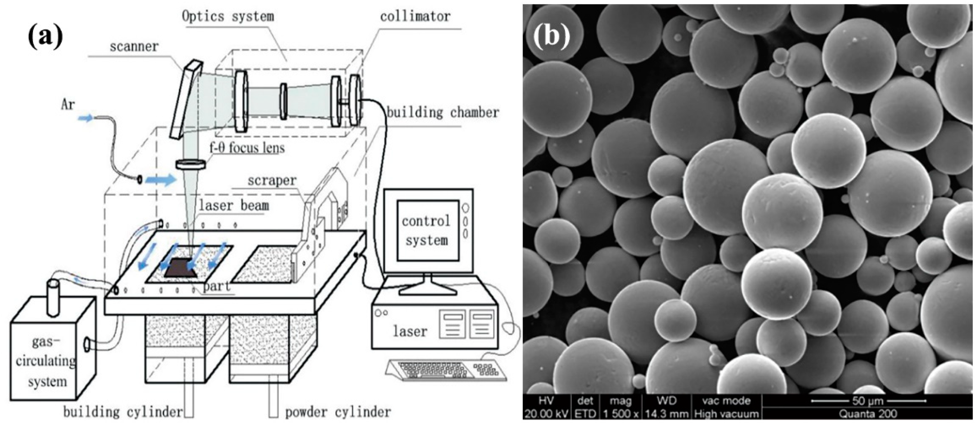
The experiments were carried out using a self-developed selective laser melting (SLM) machine, a DiMetal-100 (SCUT, Guangzhou, China). Figure 1a (reproduced from reference [21]) displays the principles of the DiMetal-100 SLM manufacturing equipment. The setup consisted of a fiber laser, optical-path transmission unit, sealing chamber (including powder recoating device), mechanical drive, control systems, and processing software. The laser was directed using a scanning galvanometer, which focused it through an F-θ lens for selectively melting the metallic powder on the plane, followed by layer-wise stacking into a metal part. The machine had a scanning speed in the range 10–5000 mm/s, thickness of processing layer in the range 20–100 µm, and a laser focusing spot diameter of 70 µm. The largest size of parts produced was 100 mm × 100 mm × 100 mm. Since the powder was fully melted during the process, protection of the SLM-processed parts from oxidation was essential, and achieved by completing the process in an atmosphere of argon or nitrogen with less than 0.15% O2.
Ti6Al4V powder (the composition of Ti6Al4V powder can be found in Table S1 in the Supplementary Material) from Falcon Aerotech Limited of China, which satisfied the requirements of ASTM F2924, was used for SLM fabrication. The Ti6Al4V powder viewed at a magnification of 1500× using scanning electron microscopy (SEM, Nova NanoSEM 430, FEI company, Hillsboro, OR, USA) is shown in Figure 1b. It can be seen that the powder particles are almost entirely spherical and mostly not adhered to one another; the mean particle diameter of the powder was 36 μm.
2.2. Experimental Methods
2.2.1. Determination of Range for the Fabricating Parameters
A full-factor experiment was performed to obtain the optimal combination of parameters including laser power, scanning speed, layer thickness, scanning spacing, and laser spot size. Modifiability of these parameters was considered jointly, and the influence of each factor on SLM fabrication quality analyzed. Laser power “P” and scanning speed “V” were selected for studying the influence of the process parameters on the surface quality of the SLM-fabricated titanium alloy. Experimentation on the fabrication process consisted of an early stage (I) of large-range exploration and a late stage (II) of range refinement. In the early stage (I), the range was 150–400 W for laser power and 600–1600 mm/s for scanning speed, as shown in Figure 2a. According to the forming effect during stage (I), we refined and optimized the selection of parameters in order to reduce the complexity of the experiment. The narrow scanning speed range was more sustainable for optimizing parameters, and we got stage (II) building parameters. The late stage (II) of range refinement is shown in Figure 2b. In the experiment, the block size was 10 mm × 10 mm × 10 mm, 25 μm for layer thickness, 0.08 mm for hatch spacing, and scanning mode was S-shaped orthogonal scanning. In addition, following the layer thickness of 25 µm, layer thicknesses of 30 µm, 35 µm, 40 µm, and 45 µm were also used to get an optimized processing window. The principles of the fabrication are presented in Figure 2c.
2.2.2. Testing Methods
Surface morphology of the titanium alloy parts fabricated by SLM using different parameters needed to be investigated in this study, with features such as track overlap and track fabrication quality analyzed. To this end, the 3D super depth-of-field microscope VHX-5000 (KEYENCE company, Osaka, Japan) was adopted for observing surface morphology and quality of the fabricated parts, and the roughness was measured by 3D optical Profilometer from Rtec Instruments company (San Jose, CA, USA).
Then, in order to study the influence of heat treatment on the ductility performance of the SLM-fabricated TC4 alloy, the heat treatment steps of our experiment were defined based on the phase diagram of TC4 and relevant investigations [22,23]. Vacuum heat treatment was performed using an N41/H Muffle furnace from Nabertherm company, Lilienthal, Germany. The heat treatment process required elevation of the temperature to 840 °C over 3 h, the temperature maintained for 2 h, then the furnace cooled until the temperature reduced to 450 °C and subsequently cooled by air.
The tensile strength of the SLM-fabricated TC4 alloy was tested. The experiment was designed to be compliant with ISO 6892-1:2016, a standard for experimentation in tensile strength of metal materials at room temperature. Other parameters of performance were also tested and analyzed in accordance with this standard. Samples with a diameter of 5 mm and scale distance of 40 mm were selected for the tensile experiment. Two groups of SLM-fabricated Ti6Al4V titanium (i.e., those with and without heat treatment) underwent the tensile experimentation using the electronic universal testing machine CMT5105 (MTS company, Eden Prairie, MN, USA), at a rate of 0.2 mm/min. The stress-strain curves were obtained from a software calculation of experimental data on stress and distortion. Subsequently, tensile strength, yield strength, and elongation were computed. Tensile fracture was observed using a NanoSEM 430 (FEI company, Hillsboro, OR, USA).
Except for tensile property, micro-hardness is taken into discussion as well. The micro-hardness test strictly complied with ISO 6507-1:2018 on micro-hardness tester HVS-3.0 (Jinan Fangyuan Testing Machine company, Jinan, China). In this article, only the upper surface micro-hardness was considered. The imposed loading was 1 kg, and the holding time was 15 s. Similarly, both the as-built samples and heat-treated samples were considered.
In order to study the influence of heat treatment on the ductility and micro-hardness of the SLM-fabricated Ti6Al4V alloy from the perspective of microcosmic structure, samples of the Ti6Al4V alloy were manufactured using SLM in compliance with ISO 4499:2011. Here, the same smooth forming parameters were adopted using a block size of 10 mm × 10 mm × 10 mm. Some samples were thermally treated using the method descried above. Finish grinding and mechanical polishing were performed on the thermally-treated and as-built samples using abrasive paper of 600, 800, 1000, and 1500 mesh in addition to a polishing cloth. The upper surface of each sample was corroded using aqua regia for approximately 60 s. The microcosmic structure of each samples’ surface metallography was observed using a Leica DMI 5000 (Leica Microsystems company, Buffalo Grove, IL, USA) at a magnification of 50–500×.
3. Results and Discussions
3.1. Classification of Surface Morphology
A macroscopic view of fabricated square parts was performed and summarized. Note that for some samples, the required energy was too great to proceed with the fabrication process and the process had to be halted by human intervention via the controlling software. From the experimental results, it is clear that for a given laser power, the quality of fabricated parts varies considerably with increased scanning speed. Meanwhile, a parameter is needed as a metric to classify the fabricated regions. Surface quality of the SLM-fabricated parts strongly correlated with the parts’ density and properties. In this paper, surface quality was defined as the principal metric to observe track quality and overlapping effectiveness. Based on the definitions put forward in References [24,25,26,27,28], the linear energy input model in Reference [28] was used to investigate the influence of energy input on surface morphology and melting status.
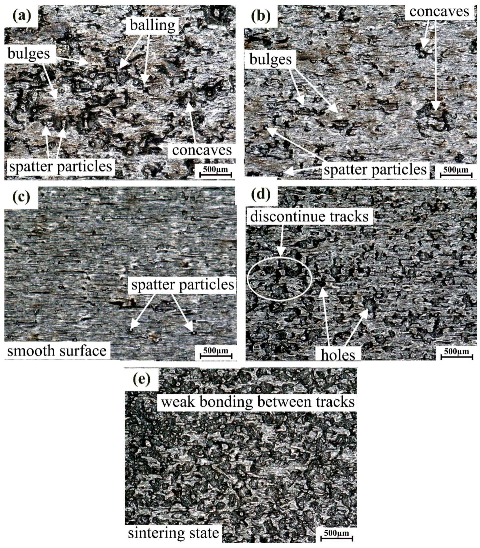
The surface morphology of parts fabricated under different parameters was observed using the VHX-5000. The observed results can be classified into five categories (i.e., severe over-melting zone, high energy density nodulizing zone, smooth forming zone, low energy density nodulizing zone and sintering zone, which can be found in Figures S1–S5 in the Supplementary Material), as shown in Figure 3. It can be seen that these regions are very distinct. The serious over-melting zone is characterized by serious distortion, roughness, and some nodulizing at the surface of the parts, as seen in Figure 3a. Its typical parameters are P = 150 W for laser power and V = 600 mm/s for scanning speed. For the high-energy density nodulizing region, the surface of the parts become smooth with slight nodulizing, but there were still irregular bulges and concaves, as seen in Figure 3b. Its typical parameters were P = 150 W for laser power and V = 700 mm/s for scanning speed. For the smooth forming zone, the surface was smooth with continuous tracks, ideal overlapping, and elimination of nodulizing, as shown in Figure 3c. Its typical parameters were P = 150 W for laser power and V = 800 mm/s for scanning speed. For the low-energy density nodulizing zone, the track at the surface of the parts was not continuous, and melting status was poor, leading to the presence of some holes between tracks. Moreover, some powders were not melted at the surface, some ball-shaped bulges were present, and the upper surface of the parts was coarse and void of metallic lustre, as shown in Figure 3d. Its typical parameters were P = 150 W for laser power and V = 1000 mm/s for scanning speed. For the sintering zone, the surface of the parts lacked metallic lustre, the track was not continuous, and most of the powder was sintered, as seen in Figure 3e. Note the surface appears sandy with weak bonding strength between tracks. Its typical parameters were P = 150 W for laser power and V = 1100 mm/s for scanning speed. Visual results indicate that nodulizing was present in both the high-energy (Figure 3b) and low-energy density nodulizing zones (Figure 3e), this result confirms the conclusions in References [29,30]. In addition, close observation of the results reveal that spatter particles were inserted into the track-overlapped surface of all samples.
Furthermore, in order to fully show and distinguish the five categories of surface, the roughness and 3D surface morphologies are shown in Figure 4. Note that for software reasons, in Figure 4, the peak of the parts is the bottom of the 3D surface morphology, and vice versa. In addition, on the Z-axis, the origin begins from the bottom of the 3D surface morphology. In Figure 4a,b, it can clearly be observed that the proportion of smooth formed tracks increased first and then decreased. As mentioned above, the bulges including ballings and concaves which were generated due to high-energy density, led to the broken scanning track. The key difference between the serious over-melting zone and high-energy density nodulizing zone is the area of normal forming plane and the depth or height of defect. Except for the height as shown in Figure 4a,b, the average roughness values Ra of multi-group samples were 20.91 μm and 16.82 μm. More smooth tracks would reduce the roughness. But in the parameter window, the roughness could not be a sufficient condition for strictly classifying the forming zones. Because of some unmeasurable defects, the reliability of roughness was weakened. In the actual exploration of processing parameters, the comprehensive evaluation method is necessary. Similarly, the incomplete melting causes the holes and breaks in the track. There is little regular big concaves or bulges in the low-energy density nodulizing surface and sintering surface, which is significantly different from the serious over-melting zone or high-energy density nodulizing zone. Considering surface roughness, the average measured values of Ra in the low-energy density nodulizing zone and sintering zone were 20.37 μm and 14.51 μm, respectively. It seems that the normal forming plane would increase the surface roughness. But in fact, the area of normal forming surface in the low-energy density nodulizing zone was bigger than that in the sintering zone. The sintered state of breaking tracks with a small thickness decreased the surface roughness. The accumulation of holes and breaking tracks exacerbated the quality of the surface.
3.2. Fabricating Parameter Optimization Window
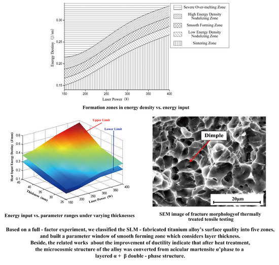
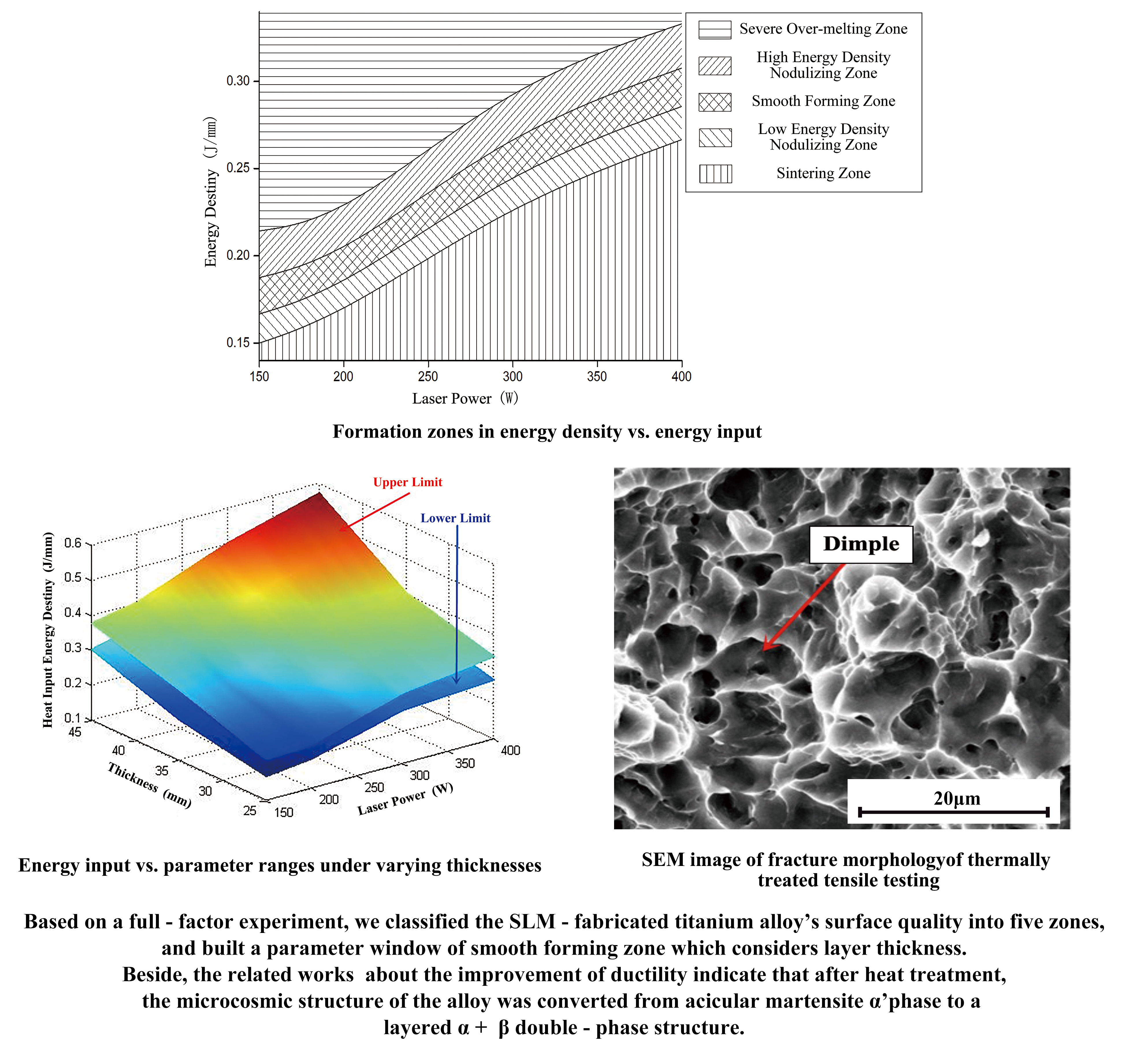
After inspecting and summarizing the surface morphology of all square parts obtained from the full-factor experiment, the SLM-fabricated titanium alloy’s surface was classified into five zones (i.e., severe over-melting zone, high-energy density nodulizing zone, smooth forming zone, low-energy density nodulizing zone, and the sintering zone). Based on Equation (1), the fabricating parameters in the experiment were converted into linear energy density. According to their respective surface morphology, all fabricating parameters were allocated to a corresponding zone. Statistical data from the experiment was utilized to compute the linear energy density of each zone, with laser power “P” as the abscissa and linear energy density “ψ” as the vertical coordinate. Given a layer thickness of 25 μm, the results and the relationship between the energy input and the forming zone is plotted in Figure 5. From this figure, it can be deduced that for SLM-fabricated titanium alloy, the range of linear energy density is not constant. Rather, it varies with laser power (scanning speed). For the smooth forming zone, the range of linear energy density varied from 0.17 to 0.22 J/mm at low laser power (150~200 W), 0.23~0.26 J/mm at P = 300 W, and 0.27~0.29 J/mm at P = 400W. Therefore, the linear energy density was not linearly related to the quality of the formed surface. The traditional belief that setting the linear energy density appropriately can necessarily guarantee surface quality is incorrect. It is also incorrect to establish direct correspondence between energy input and quality of surface formation. On the evidence of Figure 5, after limiting the fabricating parameters to the smooth forming zone, the efficiency of laser forming can be improved by increasing laser power or scanning rate.
Samples obtained at a layer thickness of 30 µm, 35 µm, 40 µm, and 45 µm were similarly analyzed. The relationship with varying layer thickness between laser energy input and parameter is plotted in Figure 6. Given a layer thickness of 25 µm, 30 μm, 35 μm, 40 μm, and 45 μm, the fabricating parameter windows of the smooth forming zone are shown in Figure 6. It can be seen that for a given layer thickness, the linear energy density of the smooth forming zone varies in the same way with increasing the laser power P. That is, the upper and lower limits of the linear energy density of the smooth forming zone increased by a large margin. Moreover, the two limits of the smooth forming zone also increased considerably with layer thickness. This can be attributed to the fact that if the quantity of powder in a layer increases, greater energy input density is required to melt the powder in order to obtain a satisfactory track and quality of formation. Therefore, the quality of SLM-fabricated titanium alloy can be guaranteed by limiting the fabricating parameters to the range of the smooth forming zone, or choosing the fabricating parameters based on the windows in Figure 6.
3.3. Analysis of Mechanical Properties
3.3.1. Tensile Properties
According to the parameter window in Figure 6, the tensile pieces were carried out with the optimal parameters, 200 W for laser power (P), 1000 mm/s for scanning speed (V), 30 μm for layer thickness, 0.08 mm for hatch space and S-shaped orthogonal scanning strategy. The orientation of the tensile pieces was parallel to the substrate.
Figure 7 and Table 1 show the stress-strain curve and mechanical properties, respectively, of SLM-fabricated Ti6Al4V alloy with and without heat treatment. Each set of data is the mean of tests on three samples. It can be seen that stress soars dramatically with the increasing of tensile strain. Regardless of process conditions, the stress–strain curve of the SLM-fabricated Ti6Al4V alloy can be divided into three stages: those of elastic deformation, yield, and dramatic decrease in stress. Prior to heat treatment, the stress–strain curve soared and decreased considerably during elongation of Ti6Al4V, and clear necking was not observed. Elongation of the parts reached 5.79% ± 0.29% prior to failure, as detailed in Table 1, and the fracture type was brittle fracture by inference. It can also be determined from Table 1 that after heat treatment, the SLM-fabricated Ti6Al4V decreased in tensile and yield strength, but still met the ASTM F136 criteria of titanium alloy for medical purposes. After heat treatment, its elongation increased to 10.28% ± 0.20%.
Furthermore, after annealing at about 700–950 °C, UTS (ultimate tensile strength) decreased by about 200 Mpa, and the elongation improved with increasing temperature and was enhanced by nearly 4–9%. The results show that after heat treatment, the titanium alloy had better ductility while reducing the strength, which is in line with Zhang’s research [10]. From Table 1, compared with published literatures, there is still some work for improvement in our heat treatment results, although the influence of different scanning strategies should be considered. According to the principle of maximum temperature and cooling rates [20,31], a group of more refined experiments could contribute to a detailed description in the microstructure evolution. In fact, the balance of tensile strength and elongation through heat treatment is more determined by an actual application’s need.
3.3.2. Micro-Hardness
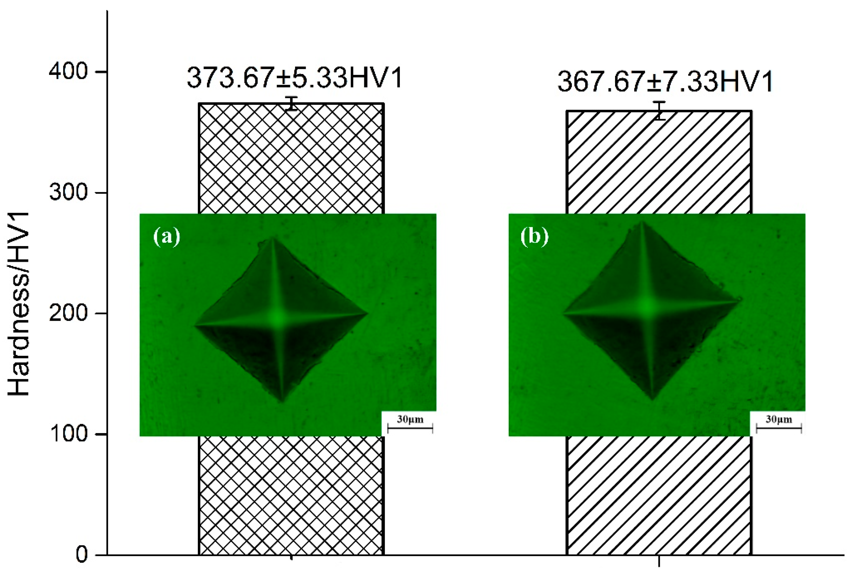
The three groups of micro-hardness samples were formed by the same optimal parameters of tensile pieces, and the heat treatment parameter was also the same. Five testing points were taken on the surface of each sample for micro-hardness testing. The spacing of the test points was 2 mm, and the results of micro-hardness are shown in Figure 8. Figure 8a is the sample without heat treatment, and Figure 8b is the sample after heat treatment. The comparison found that the surface indentation side length (D1 ≈ D2 = 72.8 μm) of the no heat treatment’s sample surface was slightly smaller than that of the surface indentation of the sample surface after heat treatment (D1 ≈ D2 = 73.5 μm). The average micro-hardness value of the upper surface of the SLM directly-made Ti6Al4V alloy was 373.67 ± 5.33 HV1. After the heat treatment, the average micro-hardness value was measured at 367.67 ± 7.33 HV1. Wang et al. [31] chose a 1000 mm/s scanning speed to build a specimen with a hardness of about 400 HV. Vilaro et al. [32] found that the sample was annealed at 800–850 °C, and the hardness decreased by about 20 HV after cooling, which was closely related to the precipitation of α phase. Moreover, the hardness can be reduced by about 35 HV when annealing at 875 °C [31], although the hardness of the sample was slightly reduced after heat treatment.
3.4. Mechanical Evolution Mechanism
Pederson et al. clarified the mechanism for the change in properties of SLM-fabricated titanium alloy following heat treatment, and they summarized the alloy phase diagram [33]. The β phase transforming temperature for Ti6Al4V is 990 ± 5 °C. If the temperature heats up more than the β phase transforming temperature, then β phase would grow quickly and become a coarse structure, leading to the increase in plasticity and a decrease in strength. The heat treatment process was set as follow: temperature was heated up to 840 °C over 3 h, the temperature was maintained for 2 h, then the furnace cooled until the temperature reduced to 450 °C and subsequently cooled by air.
The microcosmic structures of the SLM-fabricated titanium alloy following heat treatment were inspected, as shown in Figure 9. Morphology of the alloy’s microcosmic structure along the direction of laser scanning in the X–Y plane without heat treatment is presented in Figure 9a. It can be observed that prior to heat treatment, it consisted mainly of acicular martensite α’ and β phases. The reason for this is that during rapid cooling of Ti6Al4V, and new columnar β crystals formed. Before diffusion can occur, the alloy elements are converted into an oversaturated solid solution which has the same composition of the parental phase but with a different crystal structure (i.e., α’ phase martensite). It can be seen from Figure 9a that the acicular martensite α’ phase exists in abundance. Note that martensite is principally characterized by high strength and hardness. Its ductility and tenacity are dependent on the substructure of martensite (lath martensite is superior to acicular martensite in tenacity). Therefore, SLM-fabricated Ti6Al4V features high strength and low elongation prior to heat treatment. As shown in Figure 9b, the α’ phase grows tremendously and is dispersed in the β phase after recrystallization and annealing. The reason is that when the heat treatment temperature approximates to the β phase conversion temperature, β phase nucleation occurs along the boundary of the α’ phase. The closer the temperature is to the phase change temperature, the higher the content of the β phase. As the acicular martensite α’ phase converts into the layered α+β double-phase structure, the material’s elongation improves accordingly. The above results can also explain the reason why micro-hardness of SLM-ed Ti6Al4V alloy had a slight decline after heat treatment; it is due to the fact that SLM-ed Ti6Al4V microstructures were composed of the brittle and tough acicular α’ phase martensite. However, the α’ phase martensite would change to a layered α+β double-phase and it leads to the micro-hardness decline. Sallica-Leva et al. [34] also studied the malleability of SLM-fabricated titanium alloys using different heat treatments and concluded that the α’ phase decomposition is critical to improvements in malleability, which proves our findings in this experiment. After analyzing fracture morphology of the SLM-fabricated titanium alloy Ti6Al4V, it is revealed that due to heat treatment, many deeper dimples were uniformly distributed across a large area within tensile fractures of the parts. It further confirms the conversion of the fabricated titanium alloy from quasi-cleavage fracture to ductile fracture.
In order to further analyze the mechanisms of tensile property variation in the SLM-fabricated Ti6Al4V alloy after heat treatment, the morphologies of tensile fractures were inspected. Figure 10 presents tensile fractures of SLM-fabricated Ti6Al4V alloy. Figure 10b shows the fractured parts after heat treatment. It can be seen that the morphology of the tensile fracture resembles honeycombs with a number of small holes present at the fracture. This is the most fundamental criterion for fragile fracture or ductile fracture. In addition, the size and depth of the dimples are related to the material’s ductility. It can be deduced from Figure 10b, following heat treatment, that the dimples in the tensile fracture are large and deep, creating a ductile fracture. Figure 10c,d show fractures of parts without heat treatment. Many cleavage planes and torn edges with local plastic deformation are present in this fracture, in addition to a small number of dimples. Figure 10d shows that clear cleavage bands are present at the microcosmic surface morphology of the tensile fracture. Some dimples are also present at the edges, which are small and shallow. It indicates that although the parts have tenacity, the ductility is limited. Therefore, the fracture of the Ti6Al4V sample without heat treatment is a quasi-cleavage fracture. In fact, it is meaningful to discuss failure mechanisms from the view of macroscopic fracture morphology. In recent work published in [35,36], even in a smooth forming surface, roughness might lead to the origination of fatigue crack which would further evolve into a crack initiation point.
3.5. Discussion
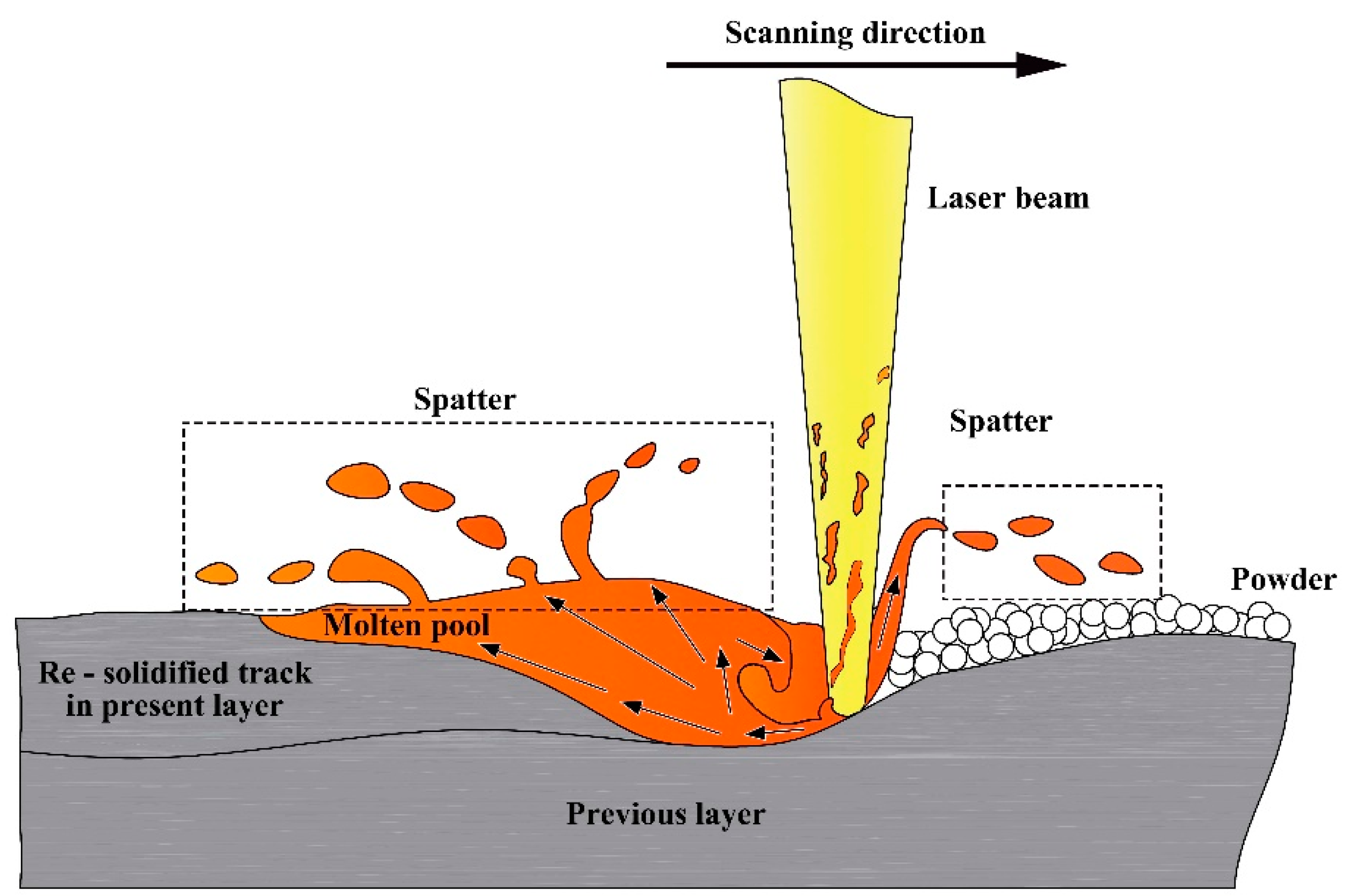
Figure 3 and Figure 4 show that, except for the smooth forming zone, the surface morphology of the other zones all had defects. Track deformation and concavity occurred within the over-melting zone. The reason is that the high density of linear energy input lengthens the cooling and solidification process of the track. As a result, the melting pool absorbs the powder at both sides more easily, leading to convexity. The convexity at the initial layer will not cause defects or other adverse influence on the fabrication of parts. But it does affect powder coating at the next layer. This problem deteriorates in subsequent layers and may well cause failure of the fabrication process. Spattering happens throughout the process, and its generated principle can be depicted, as Figure 11 shows, where one can see several types of spatter which formed during laser interaction with powder. As discussed in [21], particle spattering was mostly attributed to recoil pressure caused by instantaneous melting or even steaming of laser and powder. Another reason is that gas in the powder that is rapidly heated results in instantly swelling volume, propelling the powder to the solidification layer. Spattered particles are inserted at the surface or interior of the SLM-fabricated parts, reducing the quality of the powder coating in addition to the density and performance of the fabricated parts. As for the low-energy density nodulizing zone, there are both non-melted powder and ball-shaped bulges at the surface. The reason for this is that the linear energy density is so low that some powder does not have enough time to melt, and wettability of the liquid track is insufficient for the already solidified zone. At the surface of the sintering zone, almost no track is formed and the powder is mostly sintered.
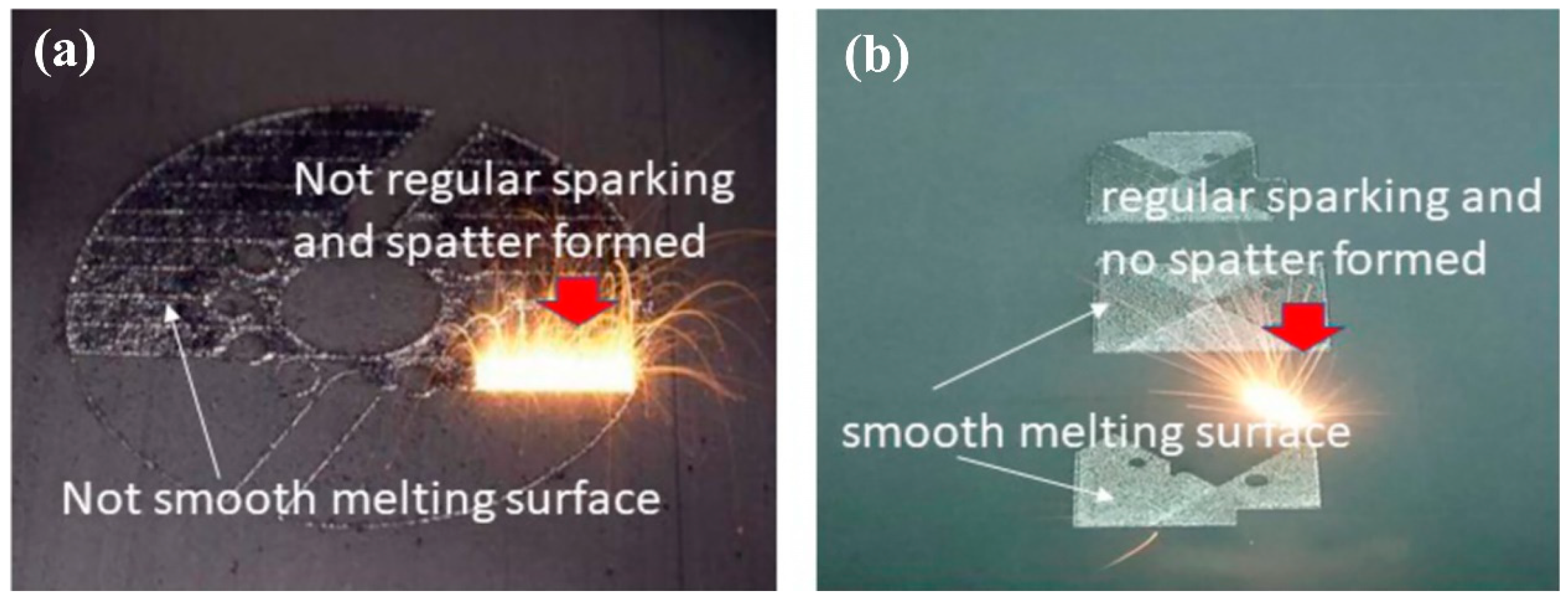
Based on the research in this study and the experience we have obtained from years of experimentation, it is clear that the surface quality of fabricated parts strongly correlates with such critical metrics as density and hardness of the parts. High-quality fabrication of parts can be ensured by observing surface quality during the fabrication process and then flexibly adjusting the energy input (i.e., laser power and scanning speed). A major bottleneck for SLM is the negative feedback in the fabrication process [37]. There are dozens of factors having enormous influence on SLM fabrication quality. It is thus of great significance to flexibly adjust parameters based on observations of one metric alone. The SLM solidification and melting pool is very small (typically 100 mm in diameter), and processing speed is usually in the range 1–3 m/s, making it extremely difficult to perform real-time monitoring and feedback control on SLM. In this paper, surface morphology of SLM-fabricated titanium alloy is classified into five categories. A CCD (central composite design) optical vision device can be adapted to capture the layer-wise surface of the SLM-fabricated parts at certain frequencies, and then measure the surface status of each layer. Subsequently, defects in the fabricated layers can be detected using real-time image processing techniques and the reasons for the defects can be analyzed. In this way, robustness and repeatability of SLM-fabricated parts can be improved significantly. Figure 12 shows the surface morphology, sparking comparisons between two typical fabrication processes. It can be seen from Figure 12a that the parts have a rough surface, irregular sparking and spatter. In Figure 12b, the parts have a smooth melting surface, while the melting layer has regular sparking but no spatter. Without observing its microcosmic structure, the fabricated parts in Figure 12b have a denser microcosmic structure and stronger mechanical properties.
Another important benefit arising from the research on parameters associated with the fabrication of titanium alloy is improvement to SLM fabrication efficiency. The traditional method for greater efficiency is to adjust the parameters based on relationships with energy input. But these relationships are impossible to be clarified without considerable efforts. Our experiment reveals that given the smooth forming conditions, the energy density ratio P/V is not fixed, and that the value of P/V is not linearly correlated with the range of optimized parameters. Therefore, in order to improve fabrication efficiency without compromising part quality, the optimal values of the speed need to be chosen from Figure 6 based on layer thickness and power.
4. Conclusions
A full-factor experiment was performed in this study to optimize the parameters for SLM fabrication of titanium alloy. The SLM-fabricated parts were classified into different categories. The parameter windows of the smooth forming zone were explored. The mechanisms concerning the improvement of ductility of the SLM-fabricated titanium alloy were investigated. The major conclusions were as follows:
- From the perspective of surface morphology, a full-factor experiment was performed to classify the SLM-fabricated titanium alloy into five zones: severe over-melting zone, high-energy density nodulizing zone, smooth forming zone, low-energy density nodulizing zone, and sintering zone.
- An optimal parameter window was established for the smooth forming zone. It was found that for the linear energy density of the smooth forming zone, the upper and lower limits increase by a large margin. Moreover, the two limits also increase considerably with a rise in layer thickness. It refutes the conclusion in some studies that there is a linear relationship between energy input and quality of fabricated parts.
- The SLM-fabricated titanium alloy was annealed using an appropriate heat treatment. After heat treatment, the structure of the alloy was converted from acicular martensite α’ phase to a layered α+β double-phase structure. Fracture type was also converted from quasi-cleavage fracture to ductile fracture. This is the reason for improvement in ductility of SLM-fabricated titanium alloy.
Supplementary Materials
The following are available online at https://www.mdpi.com/2075-4701/8/7/471/s1, Figure S1. Severe over-melting zone, Figure S2. High energy density nodulizing zone, Figure S3. Smooth forming zone, Figure S4. Low energy density nodulizing zone, Figure S5. Sintering zone; Table S1: Composition of Ti6Al4V powder.
Author Contributions
Conceptualization, D.W., Y.Y.; Data curation, D.W., W.D.; Form analysis, D.W., W.D.; Funding acquisition, D.W., Y.Y.; Investigation, D.W., W.D.; Methodology, D.W., W.D.; Project administration, Y.Y.; Supervision, D.W., Y.Y.; Visualization, W.D.; Writing—original draft, D.W., W.D.; Writing—review & editing, D.W., W.D., Y.Y. The authors would also want to express thanks to Master Hui Lin for his help on the microstructure characterization and mechanical testing in this experiment.
Funding
This research was funded by the National Natural Science Foundation of China, grant number 51775196; the Guangdong Province Science and Technology Project, grant numbers 2017B090912003, 2017A050501058, 2016B090914002, 2014B010131002, and 2015B090920002; the High-level Personnel Special Support Plan of Guangdong Province, grant number 2016TQ03X289; the Guangzhou Pearl River New Talent Project, grant number 201710010064; the Guangzhou Major Science and Technology Research for People’s livelihood through CEEUSRO Collaborative Innovation, grant number 20150802005. Di Wang thanks the China Scholarship Council for the award to study for one year at the University of Birmingham, grant number 201706155082.
Conflicts of Interest
The authors declare no conflict of interest.
References
- Leyens, C.; Peters, M. Titanium and Titanium Alloys: Fundamentals and Applications; Wiley: New York, NY, USA, 2003. [Google Scholar]
- Santos, L.V.; Trava-Airoldi, V.J.; Corat, E.J.; Nogueira, J.; Leite, N.F. DLC cold welding prevention films on a Ti6Al4V alloy for space applications. Surf. Coat. Technol. 2006, 200, 2587–2593. [Google Scholar] [CrossRef]
- Long, M.; Rack, H. Titanium alloys in total joint replacement—A materials science perspective. Biomaterials 1998, 19, 1621–1639. [Google Scholar] [CrossRef]
- Khosroshahi, M.E.; Mahmoodi, M.; Tavakoli, J. Characterization of Ti6Al4V implant surface treated by nd:yag laser and emery paper for orthopaedic applications. Appl. Surf. Sci. 2007, 253, 8772–8781. [Google Scholar] [CrossRef]
- Zhuang, J.R.; Lee, Y.T.; Hsieh, W.H.; Yang, A.-S. Determination of melt pool dimensions using DOE-FEM and RSM with process window during SLM of Ti6Al4V powder. Opt. Laser Technol. 2018, 103, 59–76. [Google Scholar] [CrossRef]
- Sun, J.; Yang, Y.; Wang, D. Mechanical properties of a Ti6Al4V porous structure produced by selective laser melting. Mater. Des. 2013, 49, 545–552. [Google Scholar] [CrossRef]
- Yadroitsev, I.; Krakhmalev, P.; Yadroitsava, I. Selective laser melting of Ti6Al4V alloy for biomedical applications: Temperature monitoring and microstructural evolution. J. Alloys Compd. 2014, 583, 404–409. [Google Scholar] [CrossRef]
- Gu, D. Laser Additive Manufacturing of High-Performance Materials; Springer: Berlin/Heidelberg, Germany, 2015. [Google Scholar]
- Wang, D.; Wang, Y.; Wu, S.; Lin, H.; Yang, Y.; Fan, S.; Gu, C.; Wang, J.; Song, C. Customized a Ti6Al4V bone plate for complex pelvic fracture by selective laser melting. Materials 2017, 10, 35. [Google Scholar] [CrossRef] [PubMed]
- Zhang, L.-C.; Attar, H. Selective laser melting of titanium alloys and titanium matrix composites for biomedical applications: A review. Adv. Eng. Mater. 2015, 18, 463–475. [Google Scholar] [CrossRef]
- Brandt, M.; Sun, S.J.; Leary, M.; Feih, S.; Elambasseril, J.; Liu, Q.C. High-value SLM aerospace components: From design to manufacture. Adv. Mater. 2013, 633, 135–147. [Google Scholar] [CrossRef]
- Traini, T.; Mangano, C.; Sammons, R.L.; Mangano, F.; Macchi, A.; Piattelli, A. Direct laser metal sintering as a new approach to fabrication of an isoelastic functionally graded material for manufacture of porous titanium dental implants. Dent. Mater. 2008, 24, 1525–1533. [Google Scholar] [CrossRef] [PubMed]
- Wehmöller, M.; Warnke, P.H.; Zilian, C.; Eufinger, H. Implant design and production—A new approach by selective laser melting. Int. Congr. Ser. 2005, 1281, 690–695. [Google Scholar] [CrossRef]
- Kawase, M.; Hayashi, T.; Asakura, M.; Mieki, A.; Fuyamada, H.; Sassa, M.; Nakano, S.; Hagiwara, M.; Shimizu, T.; Kawai, T. Cell proliferation ability of mouse fibroblast-like cells and osteoblast-like cells on a Ti-6Al-4V alloy film produced by selective laser melting. Mater. Sci. Appl. 2014, 5, 475–483. [Google Scholar] [CrossRef]
- Wang, J.H.; Cheng, J.; Li, Y.X.; Bai, P.-K. Influence of Laser Scan Speed on Density and Mechanical Properties of a Ti6Al4V Part Produced by Means of Selective Laser Melting (SLM). Lasers Eng. 2012, 23, 395–401. [Google Scholar]
- Thijs, L.; Verhaeghe, F.; Craeghs, T.; Humbeeck, J.V.; Kruth, J.-P. A study of the microstructural evolution during selective laser melting of Ti–6Al–4V. Acta Mater. 2010, 58, 3303–3312. [Google Scholar] [CrossRef]
- Song, B.; Dong, S.; Liao, H.; Coddet, C. Process parameter selection for selective laser melting of Ti6Al4V based on temperature distribution simulation and experimental sintering. Int. J. Adv. Manuf. Technol. 2011, 61, 967–974. [Google Scholar] [CrossRef]
- Facchini, L.; Magalini, E.; Robotti, P.; Molinari, A.; Höges, S.; Wissenbach, K. Ductility of a Ti-6Al-4V alloy produced by selective laser melting of prealloyed powders. Rapid Prototyp. J. 2010, 16, 450–459. [Google Scholar] [CrossRef]
- Huang, Q.; Liu, X.; Yang, X.; Zhang, R.; Shen, Z.; Feng, Q. Specific heat treatment of selective laser melted Ti–6Al–4V for biomedical applications. Front. Mater. Sci. 2015, 9, 373–381. [Google Scholar] [CrossRef]
- Vrancken, B.; Thijs, L.; Kruth, J.P.; Van Humbeeck, J. Heat treatment of Ti6Al4V produced by Selective Laser Melting: Microstructure and mechanical properties. J. Alloys Compd. 2012, 541, 177–185. [Google Scholar] [CrossRef]
- Wang, D.; Wu, S.; Fu, F.; Song, C. Mechanisms and characteristics of spatter generation in SLM processing and its effect on the properties. Mater. Des. 2017, 117, 121–130. [Google Scholar] [CrossRef]
- Wang, M.; Wu, Y.; Lu, S.; Chen, T.; Zhao, Y.; Chen, H.; Tang, Z. Fabrication and characterization of selective laser melting printed Ti–6Al–4V alloys subjected to heat treatment for customized implants design. Prog. Nat. Sci. Mater. Int. 2016, 26, 671–677. [Google Scholar] [CrossRef]
- Cain, V.; Thijs, L.; Van Humbeeck, J.; Van Hooreweder, B.; Knutsen, R. Crack propagation and fracture toughness of Ti6Al4V alloy produced by selective laser melting. Addit. Manuf. 2015, 5, 68–76. [Google Scholar] [CrossRef]
- Simchi, A.; Petzoldt, F.; Pohl, H. On the development of direct metal laser sintering for rapid tooling. J. Mater. Process. Technol. 2003, 141, 319–328. [Google Scholar] [CrossRef]
- Simchi, A. Direct laser sintering of metal powders: Mechanism, kinetics and microstructural features. Mater. Sci. Eng. A 2006, 428, 148–158. [Google Scholar] [CrossRef]
- Yadroitsev, I.; Bertrand, P.; Smurov, I. Parametric analysis of the selective laser melting process. Appl. Surf. Sci. 2007, 253, 8064–8069. [Google Scholar] [CrossRef]
- Wong, M.; Owen, I.; Sutcliffe, C.J.; Puri, A. Convective heat transfer and pressure losses across novel heat sinks fabricated by selective laser melting. Int. J. Heat Mass Transf. 2009, 52, 281–288. [Google Scholar] [CrossRef]
- Rehme, O.; Emmelmann, C. Reproducibility for properties of selective laser melting products. In Proceedings of the Third International LT-Conference on Lasers in Manufacturing, Munich, Germany, 22–25 June 2005; pp. 1–6. [Google Scholar]
- Gu, D.; Hagedorn, Y.-C.; Meiners, W.; Meng, G.; Batista, R.J.S.; Wissenbach, K.; Poprawe, R. Densification behavior, microstructure evolution, and wear performance of selective laser melting processed commercially pure titanium. Acta Mater. 2012, 60, 3849–3860. [Google Scholar] [CrossRef]
- Li, R.; Liu, J.; Shi, Y.; Wang, L.; Jiang, W. Balling behavior of stainless steel and nickel powder during selective laser melting process. Int. J. Adv. Manuf. Technol. 2011, 59, 1025–1035. [Google Scholar] [CrossRef]
- Wu, S.Q.; Lu, Y.J.; Gan, Y.L.; Huang, T.T.; Zhao, C.Q.; Lin, J.J.; Guo, S.; Lin, J.X. Microstructural evolution and microhardness of a selective-laser-melted Ti–6Al–4V alloy after post heat treatments. J. Alloys Compd. 2016, 672, 643–652. [Google Scholar] [CrossRef]
- Vilaro, T.; Colin, C.; Bartout, J.D. As-fabricated and heat-treated microstructures of the Ti-6Al-4V alloy processed by selective laser melting. Met. Mater. Trans. Coruña 2011, 42, 3190–3199. [Google Scholar] [CrossRef]
- Pederson, R.; Warren, P.R. Microstructure and Phase Transformation of Ti-6Al-4V. Department of Applied Physics and Mechanical Engineering, Lulea University of Technology. Unpublished work. 2002. [Google Scholar]
- Sallica-Leva, E.; Caram, R.; Jardini, A.L.; Fogagnolo, J.B. Ductility improvement due to martensite α′ decomposition in porous Ti–6Al–4V parts produced by selective laser melting for orthopedic implants. J. Mech. Behav. Biomed. Mater. 2016, 54, 149–158. [Google Scholar] [CrossRef] [PubMed]
- Razavi, S.M.J.; Ferro, P.; Berto, F. Fatigue Assessment of Ti–6Al–4V Circular Notched Specimens Produced by Selective Laser Melting. Strength Mater. 2017, 7, 1–9. [Google Scholar]
- Razavi, S.M.J.; Ferro, P.; Berto, F.; Torgersen, J. Fatigue strength of blunt V-notched specimens produced by selective laser melting of Ti-6Al-4V. Theor. Appl. Fract. Mech. 2017. [CrossRef]
- Spears, T.G.; Gold, S.A. In-process sensing in selective laser melting (SLM) additive manufacturing. Mater. Manuf. Innov. 2016, 5. [Google Scholar] [CrossRef]
Figure 1.
Principles, devices, and materials for selective laser melting (SLM)-based 3D metal printing: (a) illustration of SLM fabrication (reproduced from [21], with permission from Elsevier, 2018); (b) Ti-6Al-4V powder viewed by scanning electron microscopy (SEM).
Figure 1.
Principles, devices, and materials for selective laser melting (SLM)-based 3D metal printing: (a) illustration of SLM fabrication (reproduced from [21], with permission from Elsevier, 2018); (b) Ti-6Al-4V powder viewed by scanning electron microscopy (SEM).

Figure 2.
Setting parameters for SLM fabrication of Ti6Al4V: (a) Fabricating parameters for stage (I); (b) fabricating parameters for stage (II); (c) principles of S-shaped normal scanning.
Figure 2.
Setting parameters for SLM fabrication of Ti6Al4V: (a) Fabricating parameters for stage (I); (b) fabricating parameters for stage (II); (c) principles of S-shaped normal scanning.
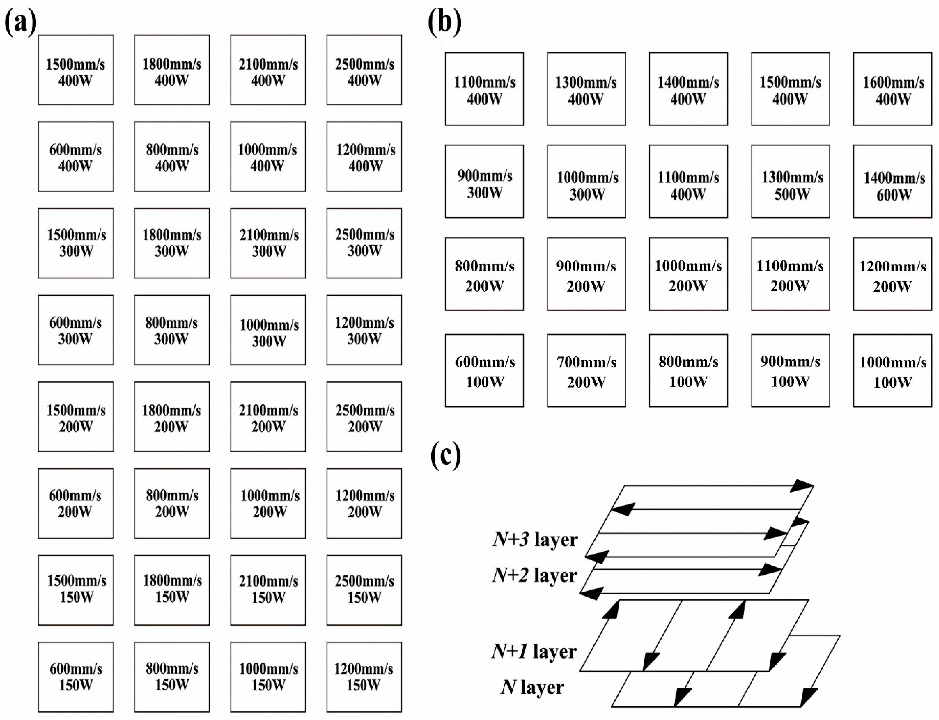
Figure 3.
Surface morphologies of parts fabricated with parameters in different ranges: (a) serious over-melting zone; (b) high-energy density nodulizing zone; (c) smooth forming zone; (d) low-energy density nodulizing zone; (e) sintering zone.
Figure 3.
Surface morphologies of parts fabricated with parameters in different ranges: (a) serious over-melting zone; (b) high-energy density nodulizing zone; (c) smooth forming zone; (d) low-energy density nodulizing zone; (e) sintering zone.

Figure 4.
3D surface morphologies of five forming zones: (a) serious over-melting zone; (b) high-energy density nodulizing zone; (c) smooth forming zone; (d) low-energy density nodulizing zone; (e) sintering zone.
Figure 4.
3D surface morphologies of five forming zones: (a) serious over-melting zone; (b) high-energy density nodulizing zone; (c) smooth forming zone; (d) low-energy density nodulizing zone; (e) sintering zone.
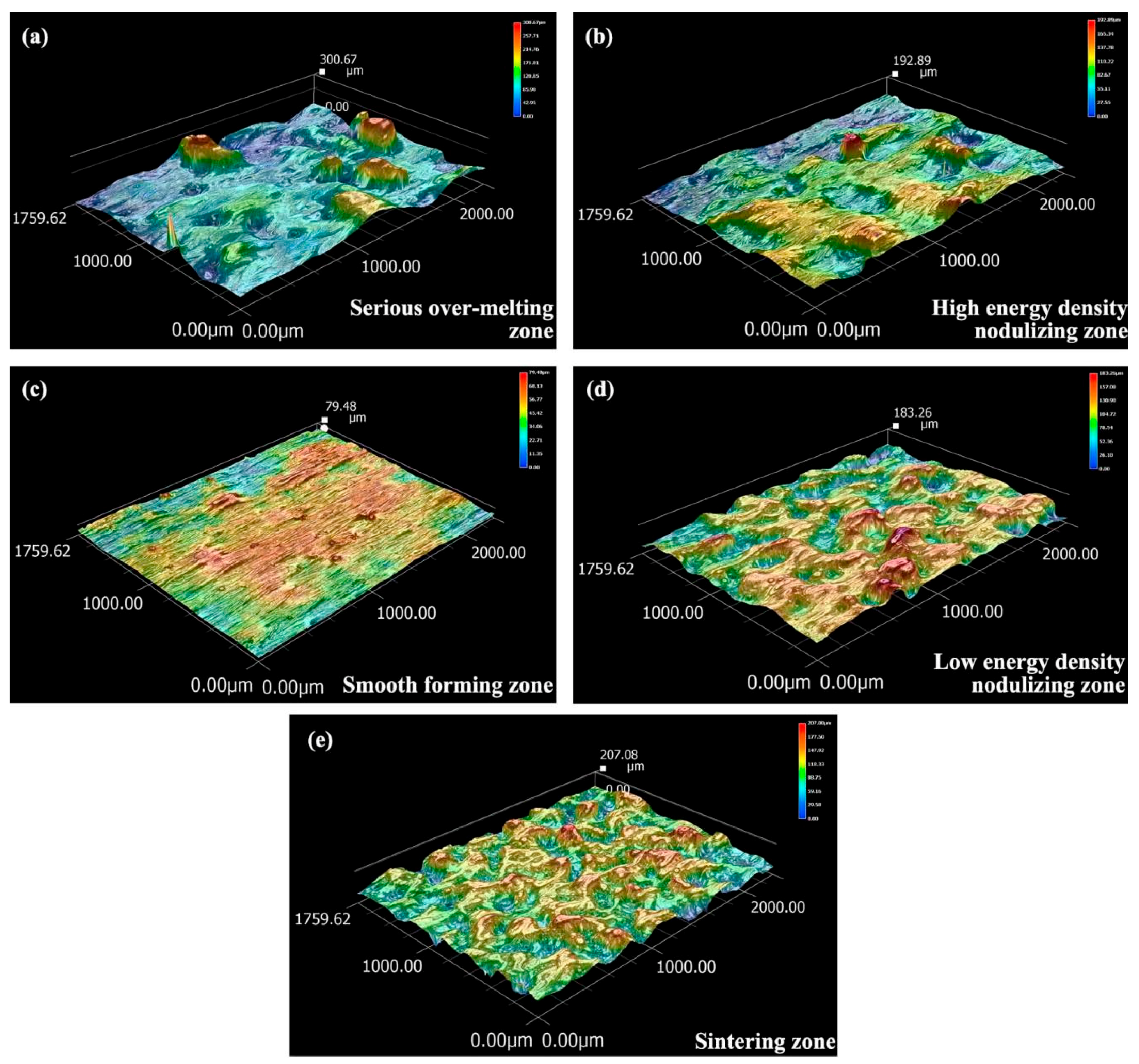
Figure 5.
Formation zones in energy density vs. energy input.
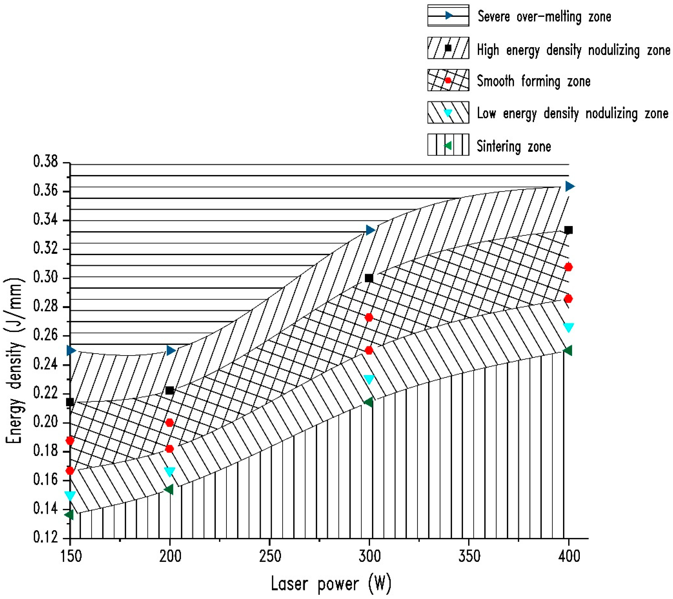
Figure 6.
Energy input vs. parameter ranges under varying thicknesses.
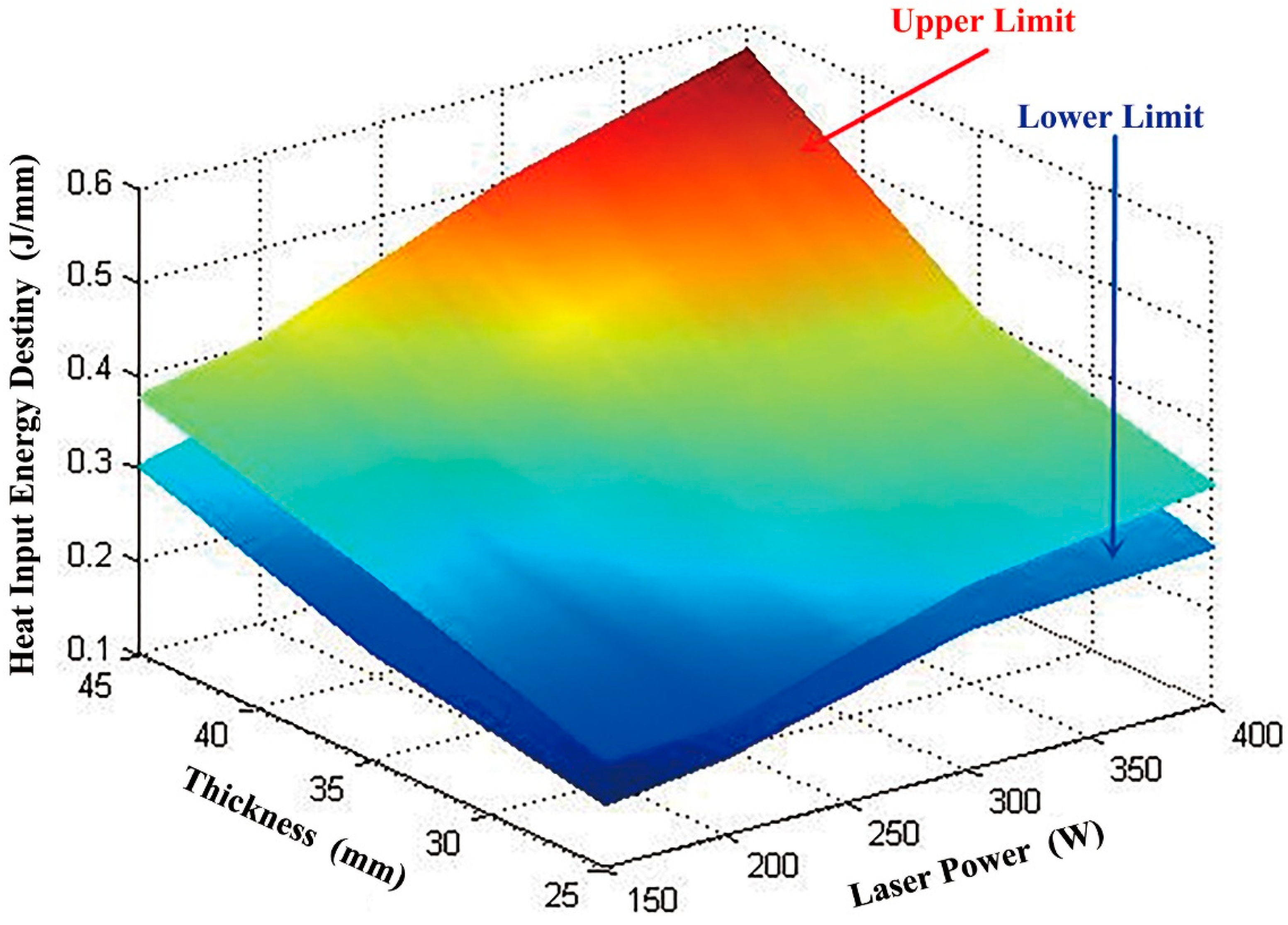
Figure 7.
Testing of tensile properties: (a) tensile bars with no heat treatment; (b) tensile bars with heat treatment; (c) strain–stress curves of Ti6Al4V alloy.
Figure 7.
Testing of tensile properties: (a) tensile bars with no heat treatment; (b) tensile bars with heat treatment; (c) strain–stress curves of Ti6Al4V alloy.

Figure 8.
Measurement points and results of micro-hardness testing for the SLM Ti6Al4V sample: (a) before heat treatment; (b) after heat treatment.
Figure 8.
Measurement points and results of micro-hardness testing for the SLM Ti6Al4V sample: (a) before heat treatment; (b) after heat treatment.

Figure 9.
Surface micro-structure of Ti6Al4V alloy: (a) before heat treatment; (b) after heat treatment (α phase is bright, β phase is dark).
Figure 9.
Surface micro-structure of Ti6Al4V alloy: (a) before heat treatment; (b) after heat treatment (α phase is bright, β phase is dark).

Figure 10.
SEM images of fracture morphology of tensile testing: (a) thermally treated sample (500×); (b) thermally treated sample (5000×); (c) as built sample (500×); (d) as built sample (2000×).
Figure 10.
SEM images of fracture morphology of tensile testing: (a) thermally treated sample (500×); (b) thermally treated sample (5000×); (c) as built sample (500×); (d) as built sample (2000×).
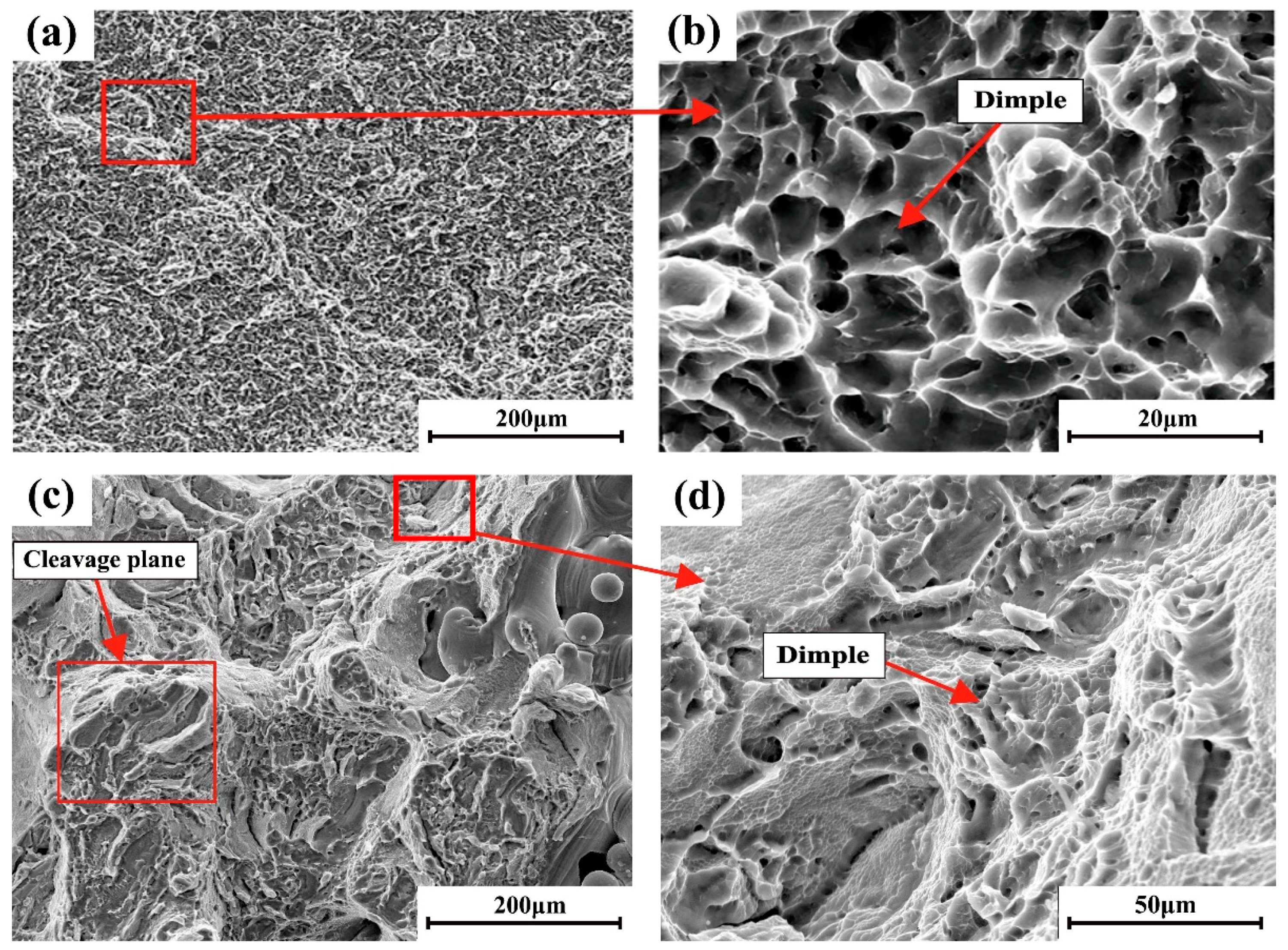
Figure 11.
Spatter generation mechanism when laser interact with powder in SLM process.

Figure 12.
Surface morphology and sparking of two typical SLM fabrication processes: (a) rough surface without regular sparking and spatter formed; (b) fine surface with regular sparking and no spatter formed.
Figure 12.
Surface morphology and sparking of two typical SLM fabrication processes: (a) rough surface without regular sparking and spatter formed; (b) fine surface with regular sparking and no spatter formed.


Table 1.
Tensile properties of Ti6Al4V before and after heat treatment.
| Manufacturing Method | Tensile Strength/MPa | Elongation/% | Notes |
|---|---|---|---|
| SLM | 1240.5 ± 7.7 | 5.79 ± 0.29 | - |
| SLM (Reference) | 1267.0 ± 5 | 7.28 ± 1.12 | [20] |
| SLM + Heat Treatment | 1068.3 ± 26.7 | 10.28 ± 0.20 | 840 °C for 3 h + tempering for 2 h + furnace cooling to 450 °C +air cooling |
| SLM + Heat Treatment (Reference one) | 1082.0 ± 34.0 | 9.04 ± 2.03 | 705 °C for 3 h + air cooling [20] |
| SLM + Heat Treatment (Reference two) | 948.0 ± 27.0 | 13.59 ± 0.32 | 940 °C for 1 h + tempering for 2 h at 650 °C + air cooling [20] |
| Ti6Al4V Alloy Forgings | ≥895.0 | ≥10.00 | ASTM B381-05 |
| Ti6Al4V Alloy for Surgical Implant Application | ≥860.0 | ≥10.00 | ASTM F136-12 |
© 2018 by the authors. Licensee MDPI, Basel, Switzerland. This article is an open access article distributed under the terms and conditions of the Creative Commons Attribution (CC BY) license (http://creativecommons.org/licenses/by/4.0/).
Share and Cite
MDPI and ACS Style
Wang, D.; Dou, W.; Yang, Y. Research on Selective Laser Melting of Ti6Al4V: Surface Morphologies, Optimized Processing Zone, and Ductility Improvement Mechanism. Metals 2018, 8, 471. https://doi.org/10.3390/met8070471
AMA Style
Wang D, Dou W, Yang Y. Research on Selective Laser Melting of Ti6Al4V: Surface Morphologies, Optimized Processing Zone, and Ductility Improvement Mechanism. Metals. 2018; 8(7):471. https://doi.org/10.3390/met8070471
Chicago/Turabian StyleWang, Di, Wenhao Dou, and Yongqiang Yang. 2018. "Research on Selective Laser Melting of Ti6Al4V: Surface Morphologies, Optimized Processing Zone, and Ductility Improvement Mechanism" Metals 8, no. 7: 471. https://doi.org/10.3390/met8070471
Note that from the first issue of 2016, this journal uses article numbers instead of page numbers. See further details here.