Article

Mo Addition to the A354 (Al–Si–Cu–Mg) Casting Alloy: Effects on Microstructure and Mechanical Properties at Room and High Temperature

1
Department of Industrial Engineering, University of Bologna, 40136 Bologna, Italy
2
Department of Civil, Chemical, Environmental and Materials Engineering, University of Bologna, 40136 Bologna, Italy
3
Ducati Motor Holding, 40132 Bologna, Italy
4
Department of Engineering and Architecture, University of Parma, 43124 Parma, Italy
*
Author to whom correspondence should be addressed.
Metals 2018, 8(6), 393; https://doi.org/10.3390/met8060393
Submission received: 1 March 2018 / Revised: 18 May 2018 / Accepted: 25 May 2018 / Published: 29 May 2018
(This article belongs to the Special Issue Microstructure and Mechanical Properties of Casting Alloys)

Abstract

:
Cast aluminum alloys are widely used in the automotive field for the production of complex engine parts. However, the mechanical properties of heat-treatable alloys (e.g., Al–Si–Mg or Al–Si–Cu–Mg) are negatively affected by prolonged exposure to temperatures higher than about 200 °C. To date, several researchers have proposed the addition of alloying elements, such as Sc or Hf, for enhancing the high temperature behavior of cast Al alloys, while Mo has not been widely investigated. The present study aimed to assess the effects of Mo addition on microstructure, mechanical properties, and thermal stability of the A354 alloy. Samples of A354 alloy with different amount of Mo (in the range 0.1 to 0.8 wt %) were produced. The casting conditions and heat treatment parameters were optimized by means of optical and scanning electron microscopy, thermal analysis and hardness tests. Tensile tests highlighted that Mo induces a moderate increase of yield strength at room temperature (about 10%), but no appreciable improvement in the performance of the alloy at 250 °C was observed.

1. Introduction

In recent years, increasing attention has been devoted to the decrease of pollution, leading car manufacturers to lighten vehicles, with the aim of reducing both fuel consumption and emissions. In this framework, engine design has been used to address the downsizing approach, consisting in the reduction of engine size, enabling mass reduction and fuel saving. Nevertheless, such design solutions generally induce an increase of operating temperatures and thermomechanical stresses in engine components. It is therefore clear that continuous development of thermally stable materials is strongly required to sustain the evolution of mechanical design needs. Among the materials used in the automotive field, thanks to their good castability and high specific stiffness and strength, cast aluminum alloys are commonly used to produce parts with complex shapes (i.e., engine blocks). However, mechanical properties of heat-treatable cast Al alloys (e.g., Al–Si–Mg or Al–Si–Cu–Mg) are negatively affected by prolonged exposure to high temperatures (greater than about 200 °C) [1,2,3,4,5,6], due to the coarsening of strengthening precipitates (i.e., overaging); as a result, the application fields of such alloys in new automotive and motorbike engine components is limited. The enhancement of the high temperature mechanical behavior of casting Al alloys is currently a major concern both from the scientific and industrial point of view. One of the most promising ways to increase thermal stability is chemical modification; the aim of the research activity is to find the most suitable alloying elements enabling the formation of strengthening phases more stable than Cu and Mg precipitates, typically found in aged Al–Si–Mg and Al–Si–Cu–Mg alloys. Several research studies [7,8,9,10] proposed the addition of innovative elements, such as Sc or Hf, but the high material cost makes them unsuitable for high volume component production [11,12].
To the authors’ best knowledge, Mo has not been deeply investigated as a possible candidate to enhance the high temperature strength of cast Al alloys. In this regard, Mo is characterized by low diffusivity in Al (2.3 × 10⁻²⁶ m2 s−1 at 300 °C) and a solid solubility, which rapidly decreases with temperature, reaching its maximum (0.25 wt %) at the peritectic reaction [13].
Some research about the use of Mo as a possible alloying element in Al–Si alloys was carried out by Farkoosh et al. [12,14], with the aim of inducing the formation of thermally stable Mo-based dispersoids in Al–Si7–Cu0.5–Mg0.3 alloy [12]. The authors proposed a two-stage solution treatment, aiming to homogenize the alloy and promote the formation of these dispersoids. While prolonged aging at 200 °C induced coarsening and ripening of θ-Al2Cu and Q-Al5Cu2Mg8Si6 precipitates, Mo-rich phases were reported by TEM analyses to be unchanged after prolonged exposure at 200 °C and 300 °C. The authors claimed a meaningful enhancement of creep and tensile properties at 300 °C, as a result of the strengthening effect exerted by the Mo-based dispersoids.
In view of the above, the present study was devoted to assessing the effects of Mo addition on microstructure, mechanical properties, and thermal stability of the A354 alloy (Al–Si9–Cu1.5–Mg0.4), used for the production of engine racing components. Molybdenum, characterized by a cost comparable to that of other alloying elements commonly used to increase thermal stability of Al alloys, such as Ni [15,16], could be a proper candidate to enhance the overaging response of A354 alloy. In particular, the research activity was addressed to evaluate possible influences of Mo addition to A354 alloy in terms of casting defects and coarse intermetallic particles; nevertheless, in view of the particular application, involving relevant thermal and mechanical stresses, the overaging response of Mo-rich alloys was evaluated, to assess the suitability of this element to increase thermal stability of A354 alloy.

2. Materials and Methods

The experimental activities were carried out in two steps.
First phase. In this preliminary research stage, samples of A354 alloy containing 0.1, 0.3, 0.5, 0.8 wt % of Mo (hereafter referred to as 0.1 Mo, 0.3 Mo, 0.5 Mo and 0.8 Mo, respectively) were produced and characterized. The aim was to identify the most promising composition, the most proper casting parameters, and heat treatment conditions for exploiting the strengthening effect of Mo, after prolonged exposure at high temperature (overaging by soaking at 250 ± 5 °C). To reach this aim, the following activities were carried out: (i) production of samples; (ii) chemical analyses; (iii) microstructural analyses; (iv) heat treatment and overaging study.
Second phase. On the basis of the results of the first research phase, the second stage was aimed to evaluate the effectiveness of Mo addition in enhancing mechanical behavior of A354 alloy both at room and high temperature. In this case, the following steps were carried out: (i) production of samples with optimized casting parameters and chemical composition; (ii) chemical analyses; (iii) microstructural analyses; (iv) tensile tests at room and high temperature; and (v) fractographic analyses.

2.1. Alloy Production

First phase. Samples were produced using A354 alloy (whose nominal chemical composition is reported in Table 1) and Al–10 wt % Mo master alloy; base and master alloys were melted in a vacuum-induction furnace at 800 °C for 30 min, in a shielding Ar atmosphere. Al–Mo master alloy was added in the appropriate amount to produce castings with 0.1, 0.3, 0.5 and 0.8 Mo weight fractions (wt %). Eutectic Si modification was carried out by adding 300 ppm of Sr to the melt. The molten alloy was electromagnetically stirred to foster Al–Mo alloy dissolution, then poured in a preheated steel die (300 °C), coated with BN spray to avoid alloy–mold interaction. After casting, chemical composition of the samples was evaluated by glow discharge optical emission spectroscopy, GDA-650 GDOES (Spectruma Analytik GmbH, Hof, Germany).
Second phase. On the basis of the results of the previous phase, since an uneven distribution of Mo was always observed, and 0.3 wt % of Mo resulted in being the most promising chemical composition, casting parameters were modified to produce a second set of samples with 0.3 wt % Mo (referred to as A354–0.3Mo* alloy). A354 alloy was molten and maintained at 900 °C for 30 min after master alloy addition; the temperature was then reduced every 10 min by 20 °C steps, until a stable temperature of 800 °C was reached. The metal was then poured in the mold, as previously described.

2.2. Heat Treatment Study

First phase. A double-step solution treatment was studied; differential thermal analyses (DTA) were carried out on the as-cast samples, in Ar atmosphere, with a heating rate of 20 °C/min, aiming to define the first-step solution temperature; the temperature of the second solution treatment step was determined by evaluating Brinell hardness of samples after a double-step solution treatment, at 510 and 540 °C for 1 h, then quenching in 60 °C water. The most promising chemical composition was evaluated by subjecting 0.1 ÷ 0.8 Mo alloys to overaging at 250 °C ± 5 °C up to 300 h, both after air cooling and water quenching, by comparing the corresponding hardness curves. Duration of aging treatment was determined by evaluating the aging curves of 0.3 Mo alloy at 180 °C. Solution treatment and aging were carried out in air, in an electric furnace with temperature control of ±5 °C. Aging and overaging curves were determined by Brinell hardness measurements by Galileo tester (Officine Galileo, Firenze, Italy), carried out on polished specimens with a load of 62.5 kg and 2.5 mm diameter steel ball (HBW 2.5/62.5 scale, hereafter referred to as HB10, where 10 is the force/diameter ratio), according to ASTM E10-08 [17].
Second phase. A354–0.3Mo* samples subjected to mechanical testing were heat treated as follows: (i) double-step solution treatment (495 °C/6 h + 540 °C/1 h) followed by water quenching at 60 °C, and aging at 180 °C/4h; (ii) double step solution treatment and air cooling. A354 reference alloy was similarly treated for comparison. Before mechanical testing at high temperature, samples were overaged for 100 h at 250 ± 5 °C.

2.3. Microstructural Analyses

Microstructure of the investigated alloys was analyzed by Axio Imager optical microscope, OM, (Zeiss, Oberkochen, Germany) and scanning electron microscope (SEM: Evo-50, FESEM: FEGSUPRA40, both Zeiss, Oberkochen, Germany) equipped with energy dispersive X-ray spectroscopy probe (Oxford Instruments, Abingdon, UK). Metallographic samples were prepared according to ASTM E3-01 [4]; grinded and polished samples were chemically etched with 0.5 vol. % HF solution to highlight microstructural features. Analyses were carried out to assess the effect of Mo addition on microstructure in the as cast condition, in particular, evaluating the presence of coarse Mo-based intermetallic phases and Mo-rich dispersoids. The tendency to dissolution of coarse Mo-based particles was evaluated by metallographic examination after solution treatment and contrast SEM image analysis [4], the latter to assess the variation of intermetallic average area fraction with increasing solution treatment time. Contrast image analyses were also carried out on optical images to evaluate the percentage area fraction covered by casting defects.

2.4. Mechanical Tests and Fractographic Analyses

Tensile tests were carried out to assess mechanical behavior of A354 and A354–0.3Mo* alloys. Tensile samples, characterized by round dog-bone shape, were machined from heat-treated bars (Figure 1, L0 = 25 mm, Lc = 28 mm, d0 = 5 mm). Room and elevated temperature (250 ± 5 °C) tensile tests were carried out according to ISO standards [18,19] at a strain rate of 0.007 mm/s on a servo-hydraulic testing machine (Italsigma, Forlì, Italy). For tensile tests at 250 °C, a resistance furnace and an extensometer for high temperature testing were used; tensile samples were maintained at 250 ± 5 °C for 1 h before performing the tests. Mechanisms of failure were investigated through SEM-EDS analyses of fracture surfaces.

3. Results and Discussion

3.1. First Phase: Preliminary Study of Mo-Rich Alloys

Aims of this research phase were to determine the most proper casting parameters to produce castings without Mo segregation, and to define the best heat treatment conditions and the most promising Mo content for enhancing thermal stability.

3.1.1. Chemical and Microstructural Analyses

Chemical analyses were carried out by GDOES in the top and the bottom of 0.1 Mo, 0.3 Mo, 0.5 Mo, and 0.8 Mo castings, melted and poured at 800 °C, aiming to evaluate Mo segregation. The results (Table 2) highlighted segregation of Mo in the bottom of the castings; this has to be related to the different density of Mo and Al (10.28 vs. 2.70 g/cm3 respectively), which leads to settling of Mo-based coarse particles in the bottom of the castings.
In this regard, Mo-rich coarse and agglomerated intermetallic particles (~50–100 μm) were observed (Figure 2), especially in samples cut from the bottom. It is thought that some of them were generated during casting (Figure 2a), while others were undissolved Mo-based needles (Figure 2b) already present in the Al–Mo master alloy (Figure 2c).
In order to improve homogenization, the casting conditions were therefore changed by melting the alloy at 900 °C, soaking for 30 min, and then pouring at 800 °C to foster dissolution of Mo-rich intermetallics and Mo diffusion.

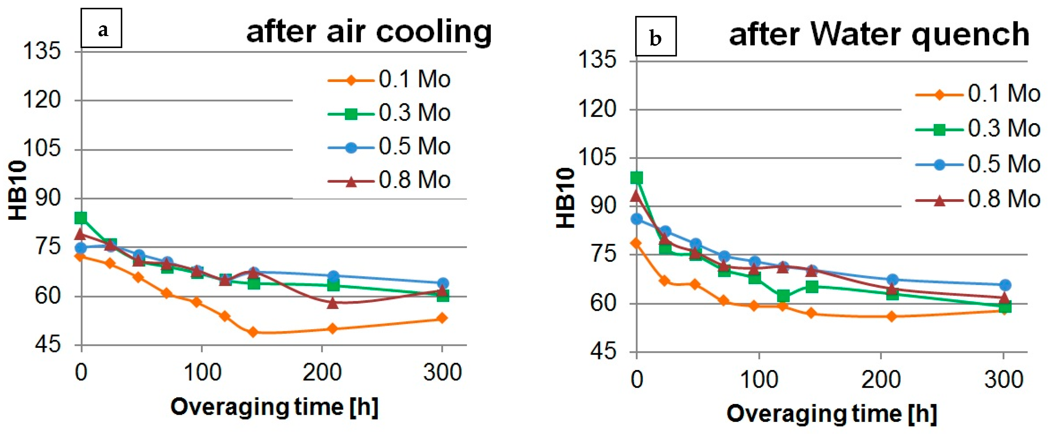
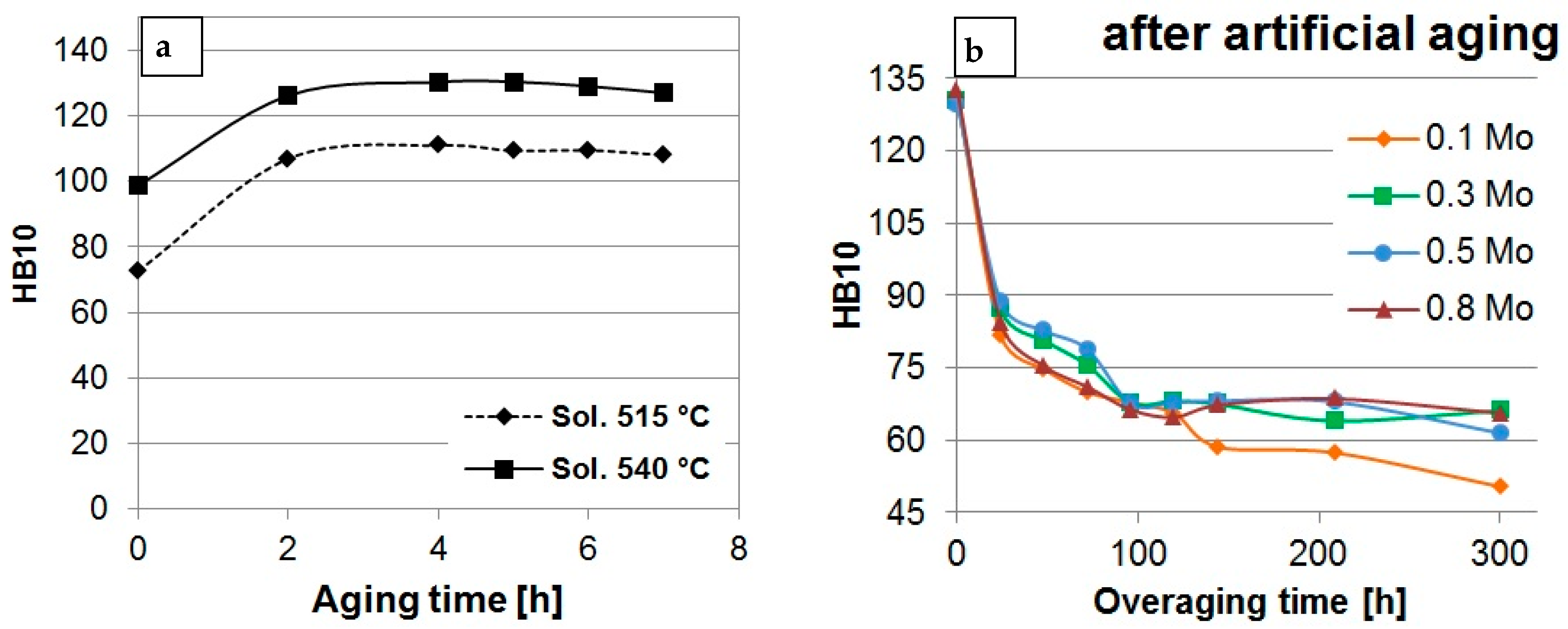
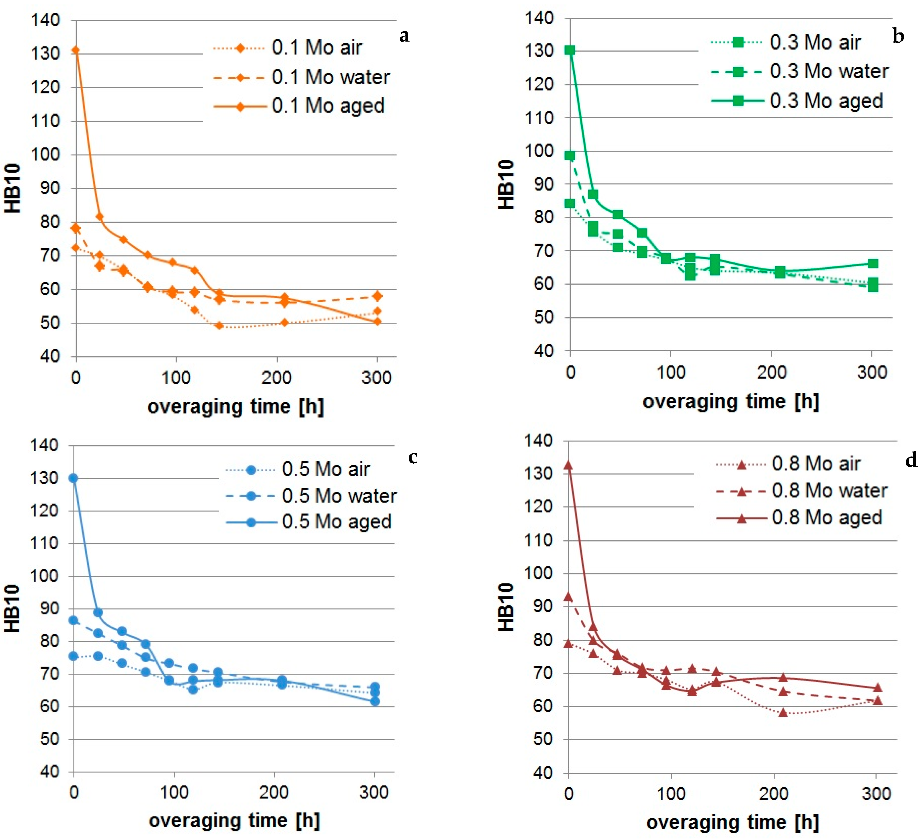
3.1.2. Heat Treatment and Overaging of Mo-rich Alloys

Thermal analyses on the as cast Mo-rich alloys (Figure 3) highlighted the presence of an endothermic peak at 509 °C, the same present in A354 base alloy [6]. It was demonstrated by the authors [6] that a first solution step at 495 °C for 6 h is necessary to dissolve such a low melting phase, as can be seen by comparing thermographs before and after the first solution treatment step in Figure 3 [6]. In view of this, samples of 0.1 Mo ÷ 0.8 Mo alloys were subjected to a first solution step, 6 h at 495 °C.
A second solution step was necessary to dissolve the remaining Cu- and Mg-based intermetallics and to foster the precipitation of strengthening Mo-based dispersoids, according to [12]; two solution temperatures were investigated, 515 and 540 °C. Aiming to evaluate the most proper solution temperature, the hardness of 0.1 Mo ÷ 0.8 Mo alloys was measured after solution treatment, consisting in 6 h at 495 °C (first step), then 1 h at 515 and 540 °C, followed by water quenching. Corresponding hardness values are compared in Figure 4. In all the investigated compositions, 540 °C led to higher hardness in comparison to 515 °C; 540 °C/1 h was therefore chosen as the second step solution treatment. This result is in agreement with [12], stating that solutioning at 540 °C leads to a higher mobility of Mo, thus enabling the precipitation of Mo-based dispersoids. The maximum hardness value (100 HB) was measured for the 0.3 wt % Mo alloy.
The effect of Mo content on the overaging behavior (induced by soaking at 250 °C) was evaluated in two different conditions: air cooling and water quenching at 60 °C, after double-step solution treatment. Figure 5 shows the variation of hardness with overaging time. Among the investigated compositions, 0.1 Mo alloy showed the lowest hardness values after overaging; on the other hand, no remarkable difference was observed for the alloys containing 0.3, 0.5, and 0.8 wt % Mo.
Since in Al–Mo system, the maximum solid solubility of Mo in Al is 0.25 wt % at the peritectic point (~660 °C) [13], additions of Mo in 0.5 wt % and 0.8 wt % are likely to result in the formation of higher amounts of coarse primary particles, which do not contribute to overaging resistance, reflecting the similarity of 0.3 Mo, 0.5 Mo, and 0.8 Mo alloys. Based on these preliminary results, 0.3 wt % Mo content was therefore chosen as the most promising composition for the successive research steps.
Aging treatment for Mo-containing alloys was defined on the basis of previous works [6] of the authors, carried out on A354 alloy, considering that aging precipitation is only related to Cu and Mg. Since the optimal aging temperature for this alloy was identified to be 180 °C [6], the aging curve at this temperature was determined, to identify the proper time to peak. Aging curves of 0.3 Mo are reported, as an example, in Figure 6a. Hardness of the alloy reaches the maximum value, about 130 HB, after 4 h of aging, remaining stable until the maximum aging time investigated, 7 h. The selected aging condition was therefore 180 °C/4 h. Figure 6 also reports the aging curve with the second step at 515 °C; it is shown that solution treatment at 540 °C is more effective, leading to higher hardness values (~+20 HB) with respect to 515 °C.
Figure 6b shows the overaging behavior of all the investigated alloys after artificial aging treatment (180 °C/4 h). Most of the strengthening effects related to Cu- and Mg-based aging precipitates (β’ (Mg2Si), θ’ (Al2Cu), S’ phase (Al2CuMg), and Q’ phase (Al5Cu2Mg8Si6)) are lost after 24 h of soaking at 250 °C, when a hardness decrease of about 35% was, in fact, observed. After 300 h of overaging, the alloy hardness is basically the same among the different conditions, irrespective of chemical composition. At this time, a hardness plateau of 66 HB10 is registered (55 HB10 for 0.1 Mo alloy).
Comparative overaging curves for each alloy composition are presented in Figure 7. As expected, in each investigated composition, hardness of quenched alloys (overaging time equal to 0) is always higher in comparison to the corresponding air cooling condition. This difference is explained by a combined strengthening effect related to both the super-saturated solid solution resulting from quenching, and the natural aging process. Such reinforcing action is, however, gradually lost with high temperature exposure during overaging, as a result of diffusion phenomena.

3.2. Second Phase: Study of A354–0.3Mo* Alloy

Based on the results of the first research phase, samples containing 0.3 wt % Mo (referred to as A354–0.3Mo*) were produced with improved casting parameters: the alloy was melted at 900 °C, maintained at this temperature for 30 min, and then poured at 800 °C, aiming to obtain a homogeneous distribution of Mo.

3.2.1. Chemical Analysis of A354–0.3Mo* Samples

Results of chemical analyses carried out on A354–0.3Mo* alloy are reported in Table 3; it is shown that modified casting parameters allow for obtaining a more homogeneous composition in the casting (see for comparison Table 2 for 0.3 Mo alloy).

3.2.2. Microstructural Characterization

According to chemical analyses, reporting compositional homogeneity, microstructural analyses of A354–0.3Mo* alloy showed a reduction of both Mo-based needles and intermetallic clusters. Figure 8 shows the overall microstructure at low magnification (Figure 8a); the typical microstructure of an Al–Si hypoeutectic alloy was observed, consisting of α-Al dendrites and surrounding eutectic structure. The secondary dendrite arm spacing (SDAS) was equal to 30 ± 5 μm.
Despite the addition of 300 ppm of Sr in all the produced castings, GDOES analyses highlighted that, in Mo-containing alloys, the distribution of Sr is not homogeneous (ranging between 0 and 400 Sr ppm depending on the specific zone). As a result, microstructure was correspondingly more or less modified. For instance, Figure 8c,d show completely modified A354 and 0.1 Mo samples and partially unmodified A354–0.3Mo* alloy. Further investigations are needed to understand if an interaction between Mo and Sr exists, leading to such uneven Sr distribution. It should be pointed out that A354–0.3Mo* and A354 alloys (Figure 9) differ for casting defects content, namely, gas pores and interdendritic shrinkages. The average area fraction of casting defects (gas pores and interdendritic shrinkage cavities) ranged between 0.2% and 0.8% in the A354 alloy, while between 0.2% and 2% in case of the A354–0.3Mo* alloy; this suggests that the addition of Mo influenced castability of A354 alloy. Such increase in the defect content could also be related to an indirect contaminant effect, due to the presence of trapped gas or oxides within the Al–Mo master alloy used as starting material to produce Mo-rich alloys.
The typical Cu- and Mg-based intermetallic phases, found in the as cast A354, were also observed in the A354–0.3Mo* alloy (Figure 10 and Figure 11).
Eutectic and block-like θ-Al2Cu phases, as well Q-Al5Cu2Mg8Si6 and π-Al8Mg3FeSi6 particles, were observed. In addition to the previously mentioned particles, Mo-based intermetallics were also found (Figure 11), showing two different morphologies: (i) block-like particles, observed mostly in the interdendritic regions, containing Al, Si, Fe, and Mo, generally in association with other intermetallics, in particular, θ-Al2Cu particles (Figure 11a); (ii) star-like particles in the α-Al region, containing only Al, Mo, and Si (Figure 11b). It is thought that the two morphologies are formed in different moments during solidification of the A354–0.3Mo* alloy: in the molten alloy, as primary particles, in case of polygonal Al–Mo–Si particles, while during the last stages of solidification, in the case of Al–Si–Fe–Mo phases. No β-Fe needles were found. The reason could be related to the presence of Mo, inducing the formation of the abovementioned Al–Si–Fe–Mo particles, thus preventing the nucleation of β-Al5FeSi phases, as also reported by Farkoosh et al. [12].
Microstructure of the as-cast state was compared to that of solution-treated samples (Figure 12), showing a marked decrease in the area fraction (AF) of intermetallic particles, as a result of dissolution process. Only very small particles were observed after solution at 540 °C: most of the Al2Cu phases found in the as-cast condition (Figure 12a) were, in fact, dissolved after 1 h at 540 °C (Figure 12b).
SEM-EDS analyses revealed that the only intermetallic particles that remained after solution treatment were block-like and star-like Mo-rich phases (Figure 13).
It is thought that the presence of such Mo-based particles reduced the Mo content available for dispersoid precipitation during solution treatment at 540 °C, therefore limiting the resistance to overaging of the alloy. Steps forward in casting optimization of the alloy should be done, for example, by evaluating a faster solidification rate to reduce the size and amount of Al–Si–Fe–Mo block-like particles, formed during last stages of solidification. A further tuning of the alloy composition, with an amount of Mo close to the peritectic composition (0.25 wt %) and a reduction of Fe content, could limit the formation of block-like particles, leaving more Mo available for the formation of stable phases.
The presence of Mo-based dispersoids was preliminarily assessed by FESEM analyses. Figure 14 shows the comparison between A354 base alloy and A354–0.3Mo* alloy, both subjected to T6 treatment (double step solution, water quench, artificial aging), overaging by soaking at 250 °C for 100 h, and tensile tested at 250 °C. Both the alloys present a fine distribution of precipitates. EDS analyses shown that in A354–0.3Mo* alloy, Mo-rich phases were present (Figure 14c,d), while A354 alloy contained only Cu- and Mg-rich precipitates (Figure 14a,d). The presence of Fe was registered in such precipitates, accordingly to Farkoosh et al. [12,14]. Transmission electron microscopy (TEM) analyses are, however, needed to better understand the evolution of Mo-based phases both during solution treatment and exposure at high temperature, and to investigate the stoichiometry and morphology of Mo-rich dispersoids.

3.2.3. Tensile Tests and Fractography

A comparison of tensile properties of A354 and A354–0.3Mo* alloys is summarized in Table 4. The data refer to samples solution treated at 495 °C for 6 h and 540 °C for 1 h, water quenched, and finally aged at 180 °C for 4 h. A354–0.3Mo* alloy was also tested after solution treatment followed by air cooling, without aging, aiming to assess if this cost-effective treatment could be used instead of the T6, for components working at high temperature.
Results show that, at equal heat treatment condition, addition of 0.3 wt % of Mo resulted in an increase of yield strength (YS) at room temperature (~+10%), as compared to A354 alloy, even with a high data scatter. A similar increase was not registered in the ultimate tensile strength (UTS); this can be related to the higher solidification defect content observed in A354–0.3Mo* alloy, as compared to A354 alloy (already reported in Section 3.2.2). In fact, as also stated in [4,20,21], in heat-treatable Al alloys, YS is mainly governed by the strengthening precipitates, while UTS is remarkably influenced by solidification defects. The relationship between UTS and casting defects was confirmed also by fractographic analyses, revealing the presence of these defects mainly on the fracture surfaces of the A354–0.3Mo* samples (Figure 15).
The higher content of solidification defects, moreover, increase data scatter; this explains the higher standard deviation of tensile test results of A354–0.3Mo* alloy. Elongation to failure at room temperature of the T6 heat-treated alloys was not affected by Mo addition. After overaging and at 250 °C testing temperature, it seems that the addition of 0.3% Mo did not enhance the mechanical properties of the alloy, YS and UTS of A354 and A354–0.3Mo* being basically the same; in such conditions, the strengthening effect of Cu and Mg precipitates was partially lost, as a result of coarsening phenomena related to aging precipitates (θ, Q), leading to a marked decrease of tensile strength in comparison to the T6 state. These results are not in disagreement with literature data [12]. It should be highlighted, in fact, that soaking (i.e., overaging) and high temperature tensile tests were carried out at different temperatures in the present investigation (250 °C) with respect to the work of Farkoosh (300 °C). The latter overaging temperature has a strong effect on the growth rate of strengthening Cu-based precipitates. The difference in the overaging temperature may have a relevant influence on evolution, morphology, and amount of Cu-based strengthening precipitates present in the heat-treated and overaged Al–Si–Cu–Mg alloys. Considering, also, that in the present work, the content of Cu is about threefold that of the alloy studied by Farkoosh (1.5 vs. 0.5 wt %), it could be possible that the higher amount of Q phases formed during aging treatment and the lower soaking temperature of the present work hide, to some extent, the effect of Mo-based dispersoids, revealing no significant strength enhancement after overaging. A similar effect could have been induced by the higher silicon content. Since eutectic silicon plays a strengthening effect and it does not undergo thermal exposure degradation at these temperatures, it is possible to suppose that it contributed to hiding the strengthening effect of molybdenum after soaking at 250 °C. Moreover, Farkoosh et al. report that the hardness of the base alloy and the Mo-rich one is basically the same after exposure at 200 °C for 1 week, similarly to the present results, while a more remarkable difference between the two alloys was registered only after a long overaging time at 200 °C, i.e., one month. This suggests that for intermediate levels of overaging, namely exposure at temperatures of 200 °C for a week or 250 °C for 100 h, molybdenum addition is not effective in enhancing the alloy’s hardness.
Solution treatment, followed by air cooling, prevented the formation of a supersaturated solid solution, thus strongly reducing Cu and Mg atoms available for natural precipitation hardening. As an outcome, YS and UTS of A354–0.3Mo* alloy, in these treatment conditions, were sensibly lower in comparison to both the T6 heat-treated A354 and A354–0.3Mo* alloys. Being strongly affected by artificial aging, elongation to failure of A354–0.3Mo* alloy was correspondingly higher in the air-cooled condition, as compared to T6 state. It is noteworthy, furthermore, the behavior at high temperature of the air-cooled A354–0.3Mo* alloy, that UTS and YS after overaging were comparable with those of the T6-treated alloys. This suggests that, for applications in which long exposure to high temperature is expected, the T6 heat treatment could be replaced by a solution heat treatment followed by air cooling.
As previously stated and also shown by microstructural analyses, despite the use of improved casting parameters, coarse undissolved Mo-rich particles were still present after solution treatment in A354–0.3Mo* alloy; as a result, Mo-based intermetallics were also found on the tensile fracture surfaces (Figure 16).

4. Conclusions

The present work was aimed to evaluate the effects of Mo addition on microstructure and overaging response of the A354 (Al–Si–Cu–Mg) casting alloy. The main conclusions are as follows:
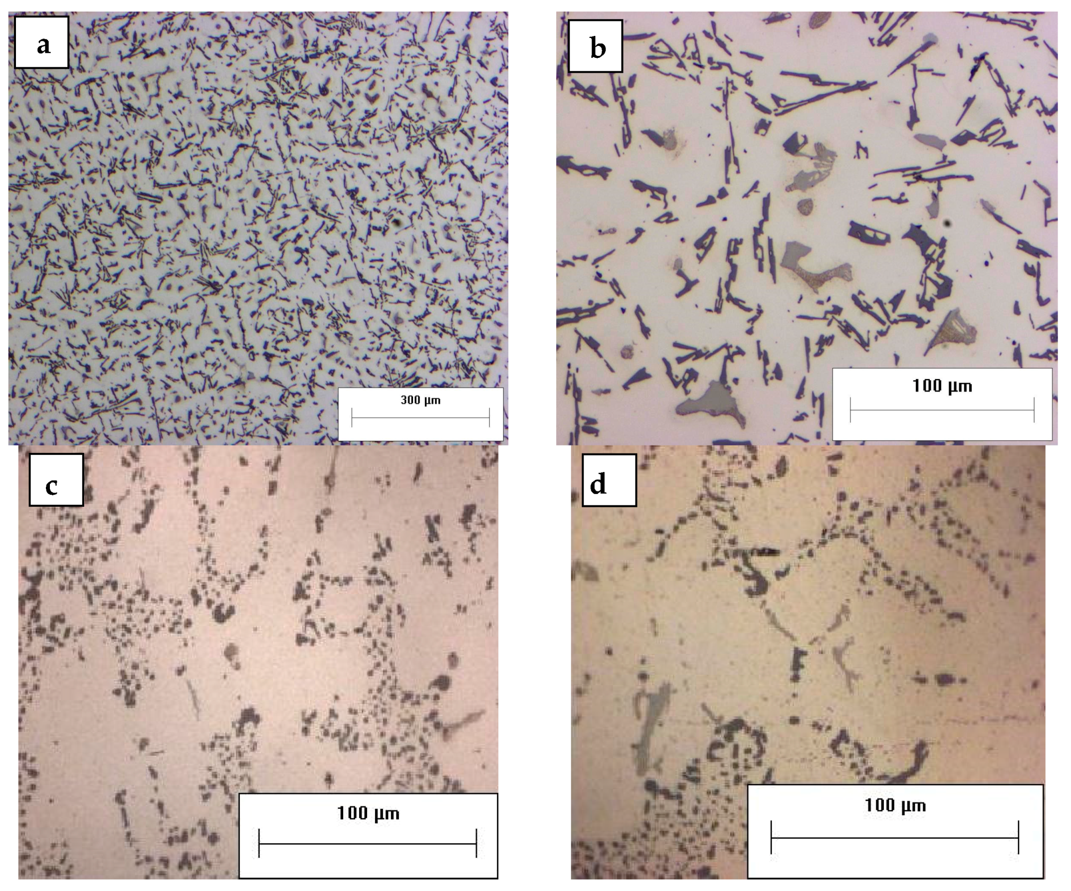
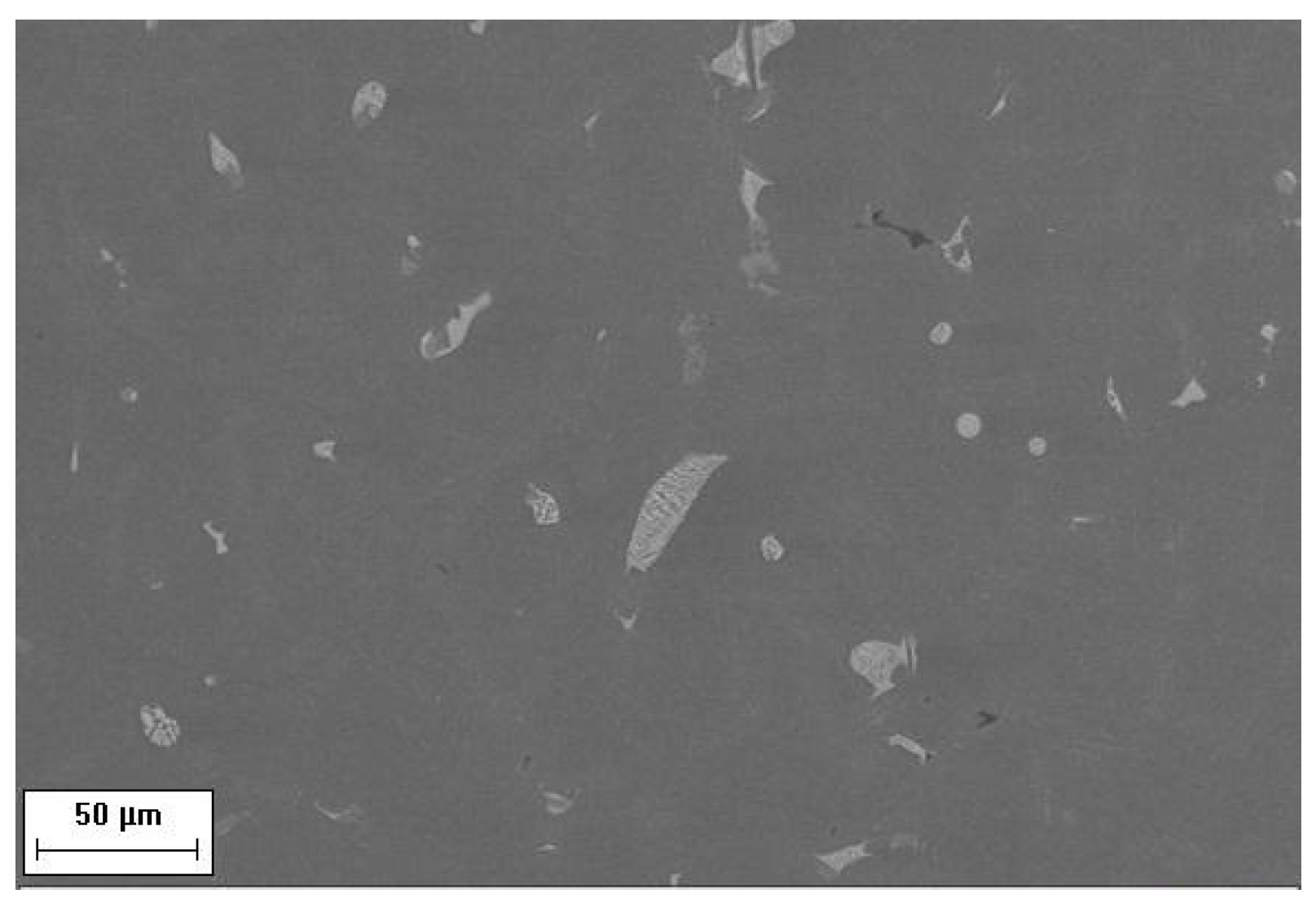
  • Addition of Mo led to segregation of coarse intermetallic particles, requiring further tuning of both casting process and alloy chemical composition.
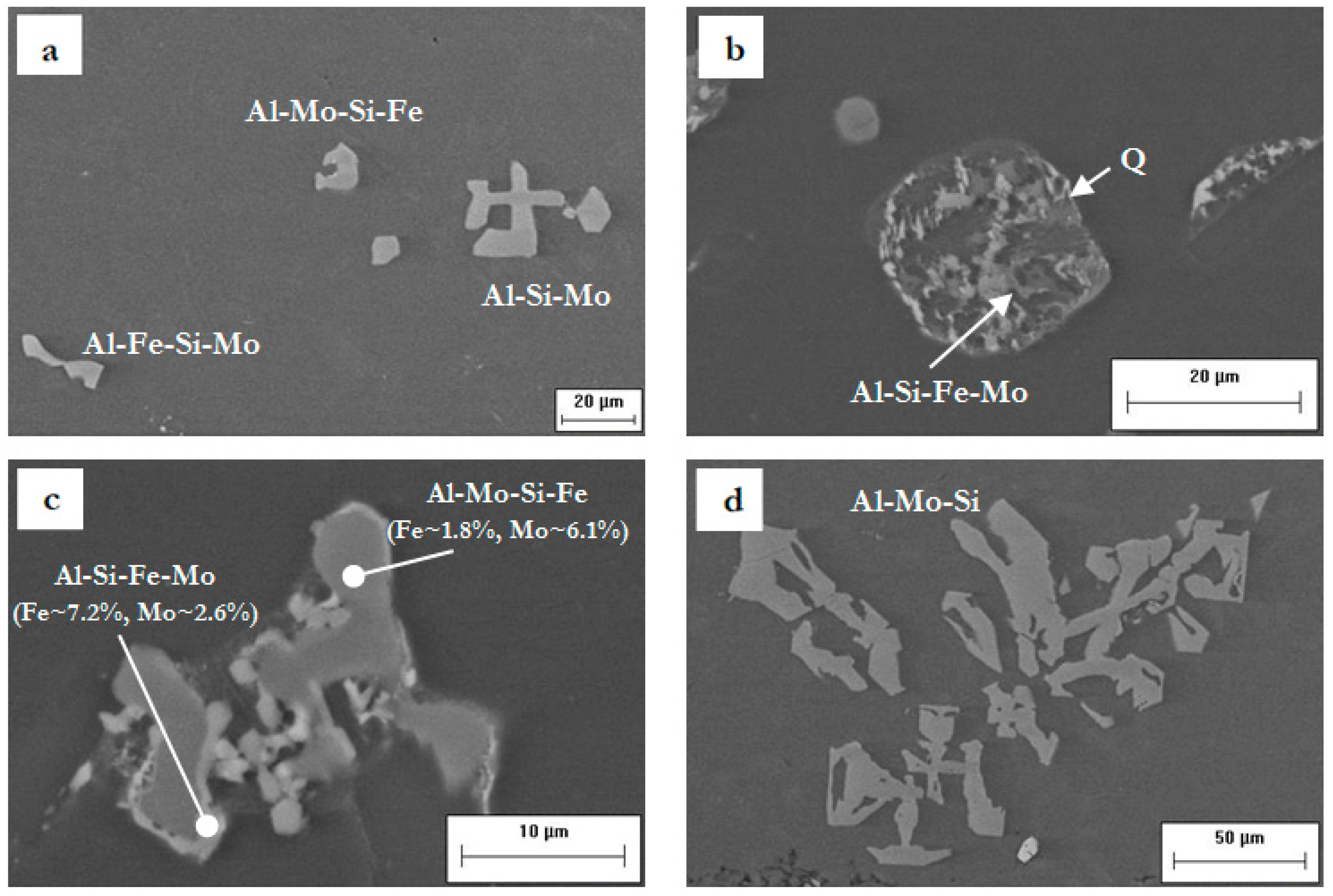
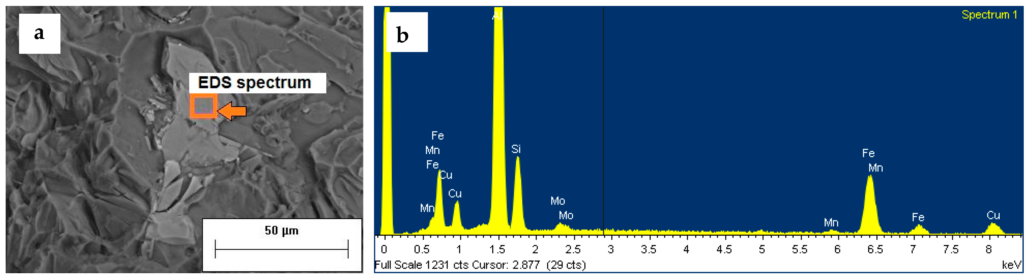
  • The addition of 0.3 wt % of Mo resulted in the formation of block-like particles, containing Al, Si, Fe, and Mo, and star-like phases, containing Al, Mo, and Si. It is thought that Mo, reacting with Fe and generating the abovementioned phases, prevents the formation of β-Fe needles. Further investigation is needed to evaluate the possible interaction between Mo and Sr, leading to uneven modification of eutectic silicon.
  • A two-step solution treatment for A354–0.3Mo* alloy was applied, consisting of a first stage at 495 °C for 6 h, and a second stage at 540 °C for 1 h. The aim of such treatment was to avoid incipient melting, to bring into solution the Cu and Mg based phases, and to induce the formation of Mo-based dispersoids. Nanometric Mo-based phases were observed in the T6 and overaged A354 alloy containing 0.3 wt % Mo.
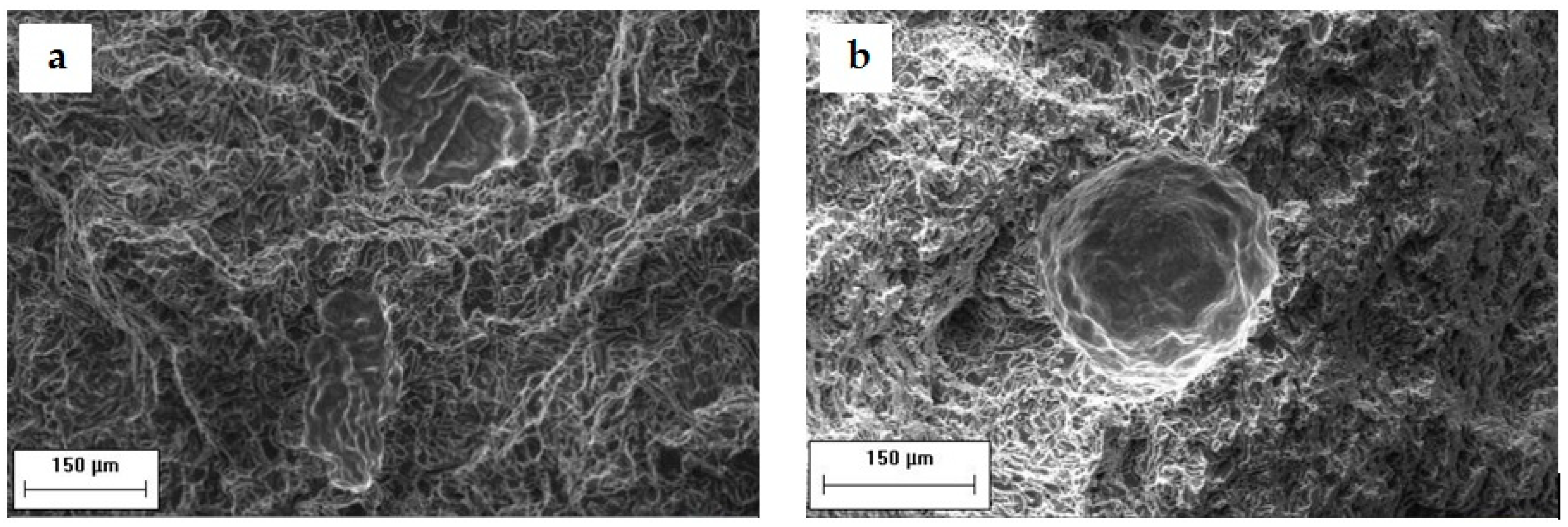
  • At room temperature and in the T6 condition, the addition of Mo led to an increase of 10% of YS in A354–0.3Mo* alloy with respect to the base A354 alloy, while it had a slight effect on UTS. The higher content of casting defects (gas pores and interdendritic shrinkages) found in Mo-containing alloy, notoriously limiting UTS rather than YS, could explain this behavior.
  • At elevated temperature (250 °C) and after overaging, the tensile behavior of base A354 and A354–0.3Mo* alloy was similar. Further TEM analyses are needed to explain this behavior.
  • The high temperature behavior of the A354–0.3Mo* alloy, solubilized and air-cooled, was comparable with that of the T6 heat-treated alloys, suggesting that, in the case of components working at high temperature, the T6 treatment could be replaced by an easier solution treatment, followed by air cooling.

Author Contributions

University of Bologna produced samples for microstructural and mechanical characterization and carried out part of the experimental activity; FESEM analyses were carried out at Parma University; all the authors contributed to data evaluation, discussion and paper writing.

Acknowledgments

The authors gratefully acknowledge Alessandro Graziani for his experimental Master Thesis work.

Conflicts of Interest

The authors declare no conflict of interest.

References

  1. Tocci, M.; Pola, A.; Raza, L.; Armellin, L.; Afeltra, U. Optimization of heat treatment parameters for a nonconventional Al-Si-Mg alloy with Cr addition by DoE method. Metall. Ital. 2016, 108, 141–144. [Google Scholar]
  2. Ceschini, L.; Morri, A.; Morri, A.; Rotundo, F.; Toschi, S. Heat treatment response and influence of overaging on mechanical properties of C355 cast aluminum alloy. La Metall. Ital. 2014, 5, 11–17. [Google Scholar]
  3. Ceschini, L.; Morri, A.; Morri, A.; Toschi, S.; Johansson, S.; Seifeddine, S. Effect of microstructure and overaging on the tensile behavior at room and elevated temperature of C355-T6 cast aluminum alloy. Mater. Des. 2015, 83, 626–634. [Google Scholar] [CrossRef]
  4. Ceschini, L.; Morri, A.; Morri, A.; Toschi, S.; Johansson, S.; Seifeddine, S. Microstructural and mechanical properties characterization of heat treated and overaged cast A354 alloy with various SDAS at room and elevated temperature. Mater. Sci. Eng. A 2015, 648, 340–349. [Google Scholar] [CrossRef]
  5. Ceschini, L.; Morri, A.; Toschi, S.; Seifeddine, S. Room and high temperature fatigue behavior of the A354 and C355 (Al–Si–Cu–Mg) alloys: Role of microstructure and heat treatment. Mater. Sci. Eng. A 2016, 653, 129–138. [Google Scholar] [CrossRef]
  6. Toschi, S. Cast Aluminum Alloys and Al-Based Nanocomposites with Enhanced Mechanical Properties at Room and High Temperature: Production and Characterization. Ph.D. Thesis, ALmaDL University of Bologna Digital Library, Bologna, Italy, 22 April 2016. [Google Scholar]
  7. Prukkanon, W.; Limmaneevichitr, C. Effect of Scandium on Mechanical Properties of Aluminum Silicon Casting After Elevated Temperature Exposure. In Proceedings of the 12th International Conference on Aluminium Alloys, Yokohama, Japan, 5–9 September 2010. [Google Scholar]
  8. Zakharov, V.V. Effect of Scandium on the Structure and Properties of Aluminum Alloys. Met. Sci. Heat Treat. 2003, 45, 246–253. [Google Scholar] [CrossRef]
  9. Costa, S.; Puga, H.; Barbosa, J.; Pinto, A.M.P. The effect of Sc additions on the microstructure and age hardening behaviour of as cast Al-Sc alloys. Mater. Des. 2012, 42, 347–352. [Google Scholar] [CrossRef] [Green Version]
  10. Jia, Z.-H.; Huang, H.-L.; Wang, X.-L.; Xing, Y.; Liu, Q. Hafnium in Aluminum Alloys: A Review. Acta Metall. Sin. 2016, 29, 105–119. [Google Scholar] [CrossRef]
  11. Javidani, M.; Larouche, D. Application of cast Al–Si alloys in internal combustion engine components. Int. Mater. Rev. 2014, 59, 132–158. [Google Scholar] [CrossRef]
  12. Farkoosh, A.R.; Chen, X.G.; Pekguleryuz, M. Dispersoid strengthening of a high temperature Al–Si–Cu–Mg alloy via Mo addition. Mater. Sci. Eng. A 2015, 620, 181–189. [Google Scholar] [CrossRef]
  13. Van Chi, N.; Bergner, D. Diffusion of Mo and Win Al, DIMETA-82: Diffusion in Metals and Alloys; Kedves, F.J., Beke, D.L., Eds.; Trans Tech Publications: Stafa-Zurich, Switzerland, 1983; pp. 334–337. [Google Scholar]
  14. Farkoosh, A.R.; Chen, X.G.; Pekguleryuz, M. Interaction between molybdenum and manganese to form effective dispersoids in an Al–Si–Cu–Mg alloy and their influence on creep resistance. Mater. Sci. Eng. A 2015, 627, 127–138. [Google Scholar] [CrossRef]
  15. Balducci, E.; Morri, A.; Ceschini, L.; Morri, A. Effect of thermal exposure on mechanical properties of EN AW-2618 and EN AW-4032 piston alloys. La Metall. Ital. 2016, 6, 89–92. [Google Scholar]
  16. Ceschini, L.; Morri, A.; Morri, A.; di Sabatino, M. Effect of thermal exposure on the residual hardness and tensile properties of the EN AW-2618A piston alloy. Mater. Sci. Eng. A 2015, 639, 288–297. [Google Scholar] [CrossRef]
  17. Standard Test Method for Brinell Hardness of Metallic Materials; ASTM E 10-08; ASM International: West Conshohocken, PA, USA, 2007.
  18. Metallic Materials-Tensile Testing-Part 1: Method of Test at Room Temperature; ISO 6892-1:2009; International Organization for Standardization: Geneva, Switzerland, 2009.
  19. Metallic Materials-Tensile Testing-Part 2: Method of Test at Elevated Temperature; ISO 6892-2:2011; International Organization for Standardization: Geneva, Switzerland, 2011.
  20. Ceschini, L.; Morri, A.; Morri, A. Effects of the delay between quenching and aging on hardness and tensile properties of A356 aluminum alloy. J. Mater. Eng. Perform. 2013, 22, 200–205. [Google Scholar] [CrossRef]
  21. Wang, Q.G. Microstructural effects on the tensile and fracture behavior of aluminum casting alloys A356/357. Metall. Mater. Trans. A 2003, 34, 2887–2899. [Google Scholar] [CrossRef]
Figure 1. Shape and dimensions (mm) of the tensile specimens; the image shows the parallel length, Lc, equal to 28 mm; the gauge length, L0—not shown in the image—is 25 mm.
Metals 08 00393 g001
Figure 2. SEM images of segregated Mo-based coarse particles: (a) clusters of Mo-rich polygonal particles observed in 0.1 Mo, (b) elongated and fragmented Mo-based phases found in 0.3 Mo casting probably deriving from (c) Mo-based needles contained in the Al–Mo10 master alloy; (df) corresponding EDS spectra [6].
Metals 08 00393 g002
Figure 3. DTA analysis carried out on as-cast 0.3 Mo alloy, showing an endothermic peak at ~509 °C (in red circle) also present in A354 base alloy (a); readapted thermographs from [6] showing the dissolution of the endothermic peak after 6 h at 495 °C (b).
Metals 08 00393 g003
Figure 4. HB10 hardness of 0.1 ÷ 0.8 Mo alloys after double step solution treatment (495 °C/6 h + 515/540 °C/1 h) and water quench; A354 base alloy was similarly treated for comparison.
Metals 08 00393 g004
Figure 5. Overaging (250 °C) curves for the A354 alloy with different Mo content, namely 0.1 wt % (0.1 Mo), 0.3 wt % (0.3 Mo), 0.5 wt % (0.5 Mo), and 0.8 wt % (0.8 Mo); overaging was carried out after double-step solution treatment followed by (a) air cooling, and (b) water quenching at 60 °C [6].
Metals 08 00393 g005
Figure 6. The 180 °C aging curves for 0.3 Mo alloy, aged after double-step solution treatment, second stage at 515 and 540 °C (a); 250 °C overaging curves for 0.1 Mo ÷ 0.8 Mo alloys in the T6 condition: double-step solution treatment, water quenching, and aging at 180 °C for 4 h (b) [6].
Metals 08 00393 g006
Figure 7. Comparative overaging curves for 0.1 Mo (a); 0.3 Mo (b); 0.5 Mo (c) and 0.8 Mo (d) alloys. For each alloy, overaging curves were obtained after air cooling (Mo air), water quenching at 60 °C (Mo water), and after artificial aging at 180 °C/4 h (Mo aged) [6].
Metals 08 00393 g007
Figure 8. OM micrographs of A354–0.3Mo* alloy in the as-cast condition at low (a) and high magnification (b,d), microstructures of as-cast A354 (c) and 0.1 Mo (d) alloys, characterized by modified eutectic silicon [6].
Metals 08 00393 g008
Figure 9. Low magnification optical images of as cast A354 alloy (a) and A354–0.3Mo* alloy (b), highlighting the higher amount of casting defects present in Mo-containing alloy.
Metals 08 00393 g009
Figure 10. SEM image showing the microstructure of as-cast A354–0.3Mo* alloy [6].
Metals 08 00393 g010
Figure 11. SEM images of A354–0.3Mo* alloy in the as-cast condition showing a block-like Al–Si–Fe–Mo intermetallic phase associated with other coarse intermetallic particles in the interdendritic region (a) and an example of star-like Al–Mo–Si particle embedded in the α-Al (b); corresponding EDS spectra are reported in (c,d) [6].
Metals 08 00393 g011
Figure 12. SEM images at the same magnification, showing the evolution of A354–0.3Mo* microstructure: as-cast condition (a), after 495 °C/6 h solution treatment followed by 540 °C/1 h (b) and 540 °C/24 h (c); percentage of intermetallic particles area fraction (AF) for each treatment condition is reported on the corresponding image [6].
Metals 08 00393 g012
Figure 13. SEM micrographs of different Mo-rich undissolved particles after solution treatment, 495 °C/6 h + 540 °C/1 h (a); small Al–Si–Fe–Mo phases associated to partially dissolved Q and θ phases (b); Al–Mo–Si–Fe phase showing Fe enrichment at the α-Al boundary (c); Al–Mo–Si phases undissolved after 24 h at 540 °C (d). The elements are listed by decreasing wt % as a result of EDS composition analysis [6].
Metals 08 00393 g013
Figure 14. FE-SEM images of A354 (a) and A354–0.3Mo* (b) alloys at the same magnification, both after T6 treatment and subsequent overaging (100 h at 250 °C); samples were extracted from high temperature tensile specimens. Nanometric Mo-based intermetallic phase observed in T6 and overaged A354–0.3Mo* alloy (c), and results of EDS spectra carried out in the two alloys on α-Al matrix (Spectrum A), intermetallic phases containing Cu/Mg (Spectrum B) and Mo (Spectrum C) data are expressed in weight percentage (d).
Metals 08 00393 g014
Figure 15. SEM images of solidification defects observed on fracture surfaces of solution treated, water quenched, and artificially aged A354–0.3Mo* specimens tested at room temperature (a) and at 250 °C after overaging at 250 °C for 100 h (b).
Metals 08 00393 g015
Figure 16. (a) SEM image of a fractured Mo-based intermetallic particle observed on artificially aged A354–0.3Mo* samples with (b) corresponding EDS spectrum [6].
Metals 08 00393 g016
Table 1. Nominal chemical composition of the A354 base alloy (wt %).
AlSiCuMgFeMnTiZnOthers
Bal.8.6–9.41.6–2.00.4–0.60–0.20–0.10–0.20–0.10–0.15
Table 2. Chemical compositions (wt %, except for Sr) at top and bottom of Mo-rich castings, measured by GDOES [6].
Expected Mo ContentGDOES Analysis PositionSiCuMgMoFeMnZnTiAl
0.1top8.911.8950.5320.1320.1260.0140.0770.126Bal.
bottom8.9152.1810.5830.1420.1470.0150.0710.178Bal.
0.3top8.5461.7860.5060.3290.1400.0130.0400.105Bal.
bottom8.8641.8670.5000.4180.1320.0120.0320.121Bal.
0.5top8.7181.7320.4800.6390.1210.0130.010.111Bal.
bottom8.6711.6530.4800.8100.1160.0130.0260.128Bal.
0.8top8.5741.5330.4320.7810.0990.0130.0330.118Bal.
bottom8.7281.4880.4200.9920.0960.0120.0260.142Bal.
Table 3. Chemical compositions (wt %, except for Sr) at top and bottom of A354–0.3Mo* casting produced by modified casting conditions, measured by GDOES [6].
Expected Mo ContentGDOES Analysis PositionSiCuMgMoFeMnZnTiAl
0.3Top8.9991.6470.4520.3220.1220.0090.0390.100Bal.
bottom9.0571.6760.4670.3380.1260.0090.0340.099Bal.
Table 4. Tensile properties of A354 and A354–0.3%Mo* alloys subjected to different heat treatment conditions, tested both at room temperature (RT) and at 250 °C after 100 h of overaging at 250 °C.
AlloyHeat TreatmentOveragingTest ConditionYield Strength (MPa)Ultimate Tensile Strength (MPa)Elongation to Failure %
A354Solution treatment (6 h @ 495 °C + 1 h @ 540 °C)–water quenching–aging (4 h @ 180 °C)NoRT280 ± 18337 ± 122.5 ± 0.8
100 h @ 250 °C250°C75 ± 286 ± 311 ± 3
A354–0.3Mo*Solution treatment (6 h @ 495 °C + 1 h @ 540 °C)–water quenching–aging (4 h @ 180 °C)NoRT305 ± 8350 ±162.5 ± 1.5
100 h @ 250 °C250°C77 ± 487 ± 47 ± 4
A354–0.3Mo*Solution treatment (6 h @ 495 °C + 1 h @ 540 °C)–air coolingNoRT173 ± 15226 ± 203 ± 1.5
100 h @ 250 °C250°C71 ± 385 ±412 ± 5

