Experimental Investigations of the In-Die Quenching Efficiency and Die Surface Temperature of Hot Stamping Aluminium Alloys


1
Department of Mechanical Engineering, Imperial College London, Exhibition Road, London SW7 2AZ, UK
2
School of Mechanical Engineering, University of Science and Technology Beijing, Beijing 100083, China
*
Author to whom correspondence should be addressed.
Metals 2018, 8(4), 231; https://doi.org/10.3390/met8040231
Submission received: 28 February 2018
/
Revised: 24 March 2018
/
Accepted: 27 March 2018
/
Published: 2 April 2018
(This article belongs to the Special Issue Material and Process Design for Lightweight Structures)
Abstract
:The in-die quenching is a key stage in the hot stamping volume production chain which determines the post-formed strength of lightweight alloy components, tool life, and hot stamping productivity. In this paper, the performance of in-die quenching, reflected by the quenching efficiency (the time of work-piece held within stamping dies) and die surface temperature during the simulated hot stamping process of AA6082, was experimentally and analytically investigated. A range of in-die quenching experiments were performed for different initial work-piece and die temperatures, quenching pressures, work-piece thickness, and die clearances, under hot stamping conditions. In addition, a one-dimensional (1D) closed-form heat transfer model was used to calculate the die surface temperature evolution that is difficult to obtain during practical manufacture situations. The results have shown that the in-die quenching efficiency can be significantly increased by decreasing the initial work-piece and die temperatures. Die clearances are required to be designed precisely to obtain sufficiently high quenching rates and satisfying post-formed strength for hot-stamped panel components. This study systematically considered an extensive variety of influencing factors on the in-die quenching performance, which can provide practical guides for stamping tool designers and manufacture systems for hot-stamping volume production.
1. Introduction
The increasing concern of air pollution and stringent legislation of greenhouse gas emissions in the transportation industry has driven the automotive and aircraft industries to use lightweight materials, such as aluminium, magnesium alloys, and composites [1,2]. Hot Form and Quench (HFQ®) is a novel and leading hot stamping technique to manufacture complex-shaped panel components of high-strength aluminium alloys [3]. During the HFQ® process, the raw aluminium alloy blank experiences solution heat treatment (SHT) to dissolve the original precipitates and dissolvable inclusions to obtain a ductile microstructure. Then, the heat treated blank is transferred to the tools and hot stamped into designed geometries. Similar to hot stamped boron steels, the hot stamped aluminium alloy components, especially for heat-treatable aluminium alloys, are required to be cold die-quenched to lower temperatures, normally less than the artificial ageing temperature. The objective of this stage is to obtain a supersaturated solid solution state, that can be artificially aged to higher post-formed strength [4], and guarantee good dimensional accuracy. Therefore, the in-die quenching is an essential and critical stage of hot-stamping volume production. The performance of the in-die quenching stage determines the post-formed strength of formed components [5], stamping tool life [6], and productivity [7], which needs to be thoroughly investigated and precisely controlled.
Heat-treatable aluminium alloys are strengthened through precipitation hardening. Hence, the post-formed strength of hot stamped aluminium alloys components is normally achieved by artificial ageing, which requires the alloy pre-quenched at a sufficiently high cooling-rate after solution heat treatment. In hot stamping aluminium alloys, such a cooling rate is obtained by in-die quenching similar to hot stamping boron steel. Until now, extensive studies have been performed on the cold-die quenching of press-hardened boron steel [8]. Intrinsically, the quenching rate is, in part, determined by the interfacial heat transfer coefficient (IHTC) between the stamping dies and formed alloys. The IHTC varies with various factors, such as the contact material pair [9], die temperature [10], contact pressure [11], surface roughness [12], lubrication [13], oxidation [14], and clearance [15], which results in the varied in-die quenching time. However, the research of in-die quenching of hot stamping aluminium alloys is still limited. Ying et al. [16] thoroughly investigated the heat transfer mechanism of HFQ® forming AA7075. The IHTC increases with increasing contact pressure within a certain range, 30–80 MPa. In addition, surface roughness and lubrication also affect the IHTC significantly. A surface roughness between 0.5 and 1 µm, and a lubricant with larger heat conductivity enhances the interfacial heat transfer. Similar findings were also obtained by Xiao et al. [17] for hot stamping AA7075. Liu et al. [18] developed a novel testing facility to measure the temperature evolutions of blank and die materials using the Gleeble 3800 thermal-mechanical simulator. The IHTCs with different tool materials and lubrication at different contact pressures were obtained using an inverse finite element (FE) methodology. The studies described previously concentrated on the determination of the IHTC values as functions of contact pressures, contact material pair and lubrication, which is believed to be useful for FE simulations.
During the volume production of hot stamping aluminium alloys, the stamping dies are subjected to severe interface conditions, such as high temperature and relatively high stress. After certain cycles of hot stamping operations, the increasing die-surface temperatures results in cooling water being required to cool the material [8]. The increased die surface temperature may induce drawbacks, including extended in-die quenching time, insufficient quenching rate, and shortened tool life due to thermal fatigue. Subsequently, the manufacturing productivity is reduced, and the strengths of hot-stamped components deteriorate. However, systematic investigations on the die temperature evolution and resulted in-die quenching efficiency under different process parameters of hot stamping aluminium alloys are still lacking.
The die surface temperature is difficult to measure precisely during hot stamping using conventional experimental methods since the die surface is always in contact with the hot work-piece. Additionally, the in-die quenching efficiency and effective quenching rate vary with several process variables, such as different initial alloy temperatures, work-piece thickness, die clearance, and contact pressure. In this study, a series of in-die quenching experiments with a variety of process parameters mentioned above were performed to evaluate the in-die quenching efficiency. In addition, a one-dimensional (1D) closed-form heat transfer model was utilised to calculate the die surface temperature evolution [19] using the experimentally-determined temperature evolutions. This is the first study that systematically investigates the in-die quenching performance from the viewpoint of hot stamping volume production. The experimental results are used to guide tooling designs and manufacturing systems of hot stamping aluminium alloys.
2. Experimentation
2.1. Material and Specimen Design
The raw material used was AA6082 in T6 condition supplied by Southwest Aluminum (Group) Co., Ltd., Chongqing, China. AA6082 is a high-strength aluminium alloy with good corrosion properties and preferably used as a material in automobile body structures. Two different thickness, 2 mm and 3 mm, were selected. The chemical composition of AA6082 is given in Table 1.
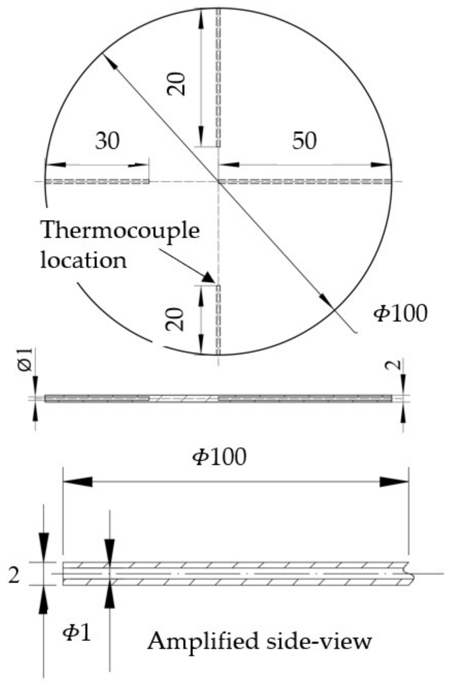
Figure 1 shows the dimensions of the circular specimen used for the in-die quenching test. Circular specimens with diameters of 100 and 150 mm were used. Four holes with a diameter of 1 mm, distributed orthogonally, were machined using electric discharging machining (EDM) through the middle of the thickness to different depths from the edge to the centre of the specimen. Thermo-couples were attached to the bottom surface of the drilled holes to allow for the precise measurements of the specimen temperature and to avoid edge effects.
2.2. Experimental Setup
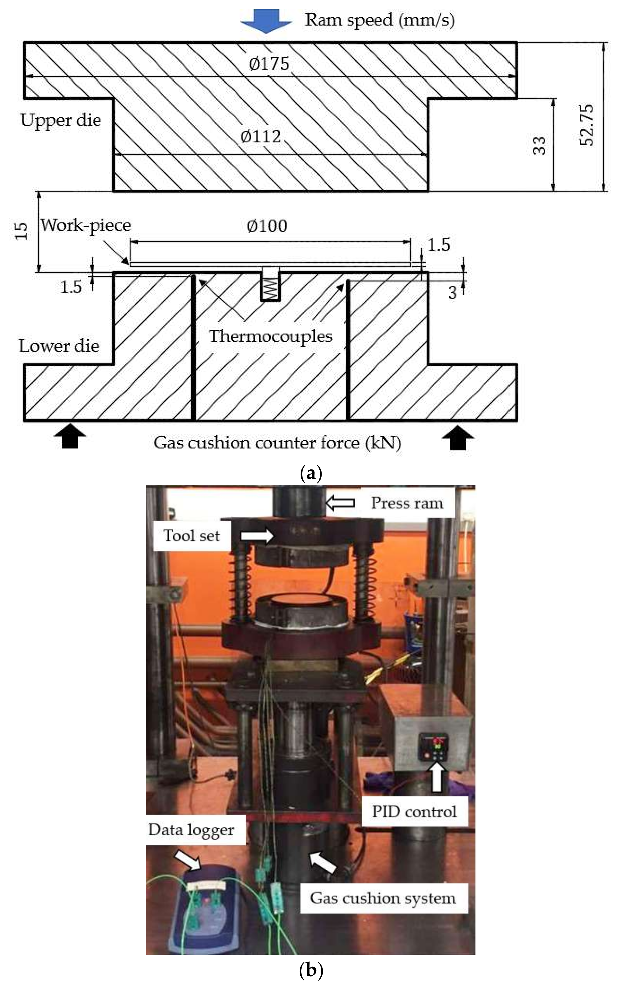
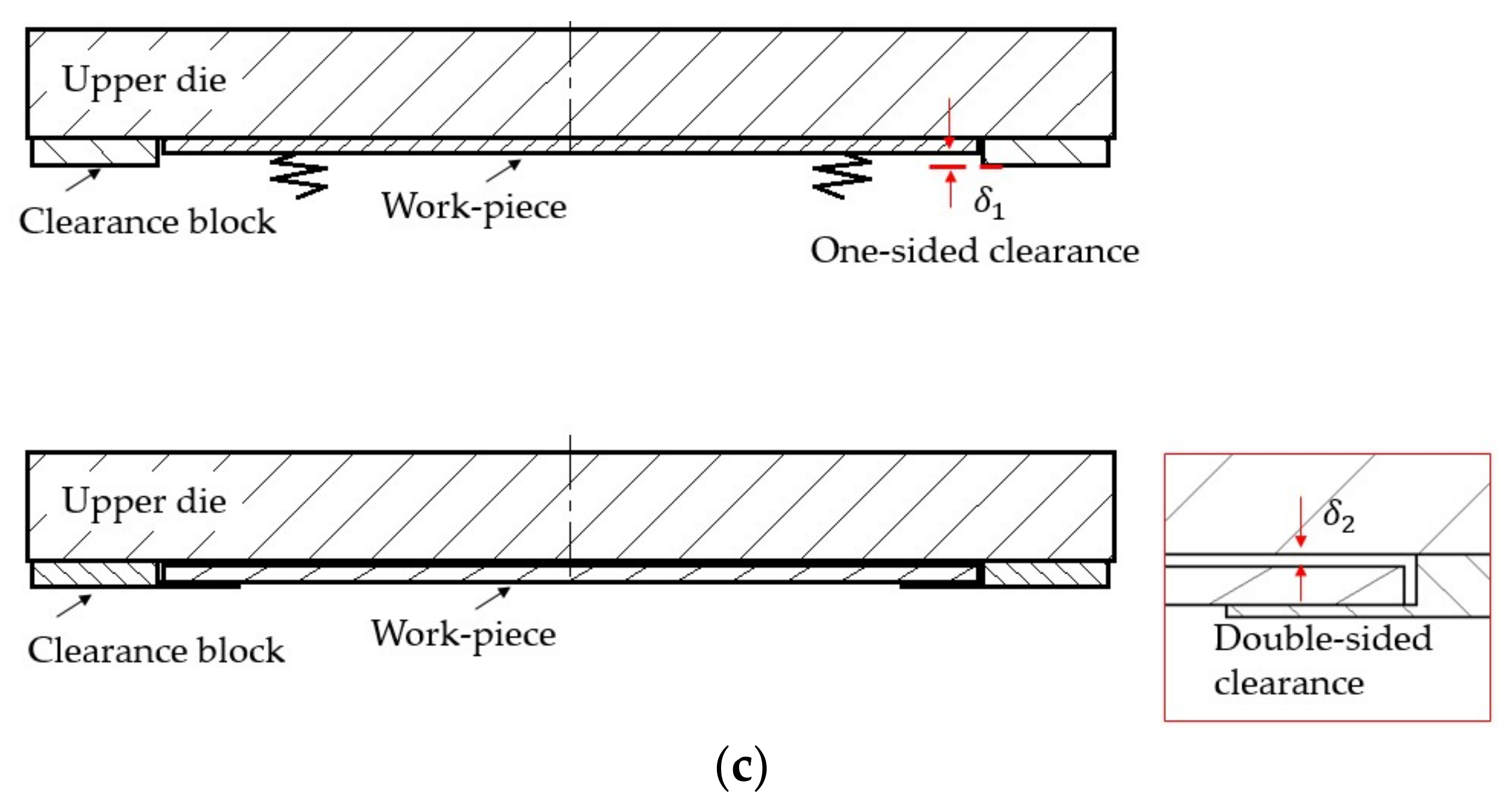
Figure 2a shows the dimensions and positions of the in-die quenching tools used to simulate the in-die quenching stage in the practical hot stamping process of aluminium alloys. In this set-up, cylindrical dies with a diameter of 112 mm were used. The tool was made of G3500 cast iron. Three thermocouples were welded inside the lower die at 1.5, 3, and 4 mm from the die surface. Figure 2b shows the complete set-up of the in-die quenching test. The die quenching rig was mounted on a 250 kN hydraulic press purchased from E.S.H. Testing Limited (Birmingham, UK). The base of this rig was supported by a gas-cushion system to provide different counter forces to simulate the in-die quenching process. The temperature evolutions of both dies and test-piece were recorded using a TC-08 Pico data logger (Pico Technology, Cambridgeshire, UK). The dies were heated to different temperatures using the heating bands attached on the periphery of the upper and lower dies in this study to simulate the temperature rise of stamping dies during the volume production of hot stamping. A Proportional Integral Derivative (PID) control system was used to control the die temperature. The upper and bottom dies were assumed to be at the same temperature due to the symmetrical geometry of the setup. Additionally, due to the clearance between the forming dies and the localised thinned areas on the formed part, there might exist some gaps between the dies and formed part, and full contact cannot be guaranteed. To simulate the clearance effect on quenching, single- and double-sided clearances were implemented into the in-die quenching rig used in previously-published research [17], as shown in Figure 2c. The clearances, either single-sided or double-sided, were obtained by inserting clearance blocks (stainless steel foils) between the upper and lower dies. The different magnitudes of clearance were achieved by altering the number of foils.
2.3. Test Programme
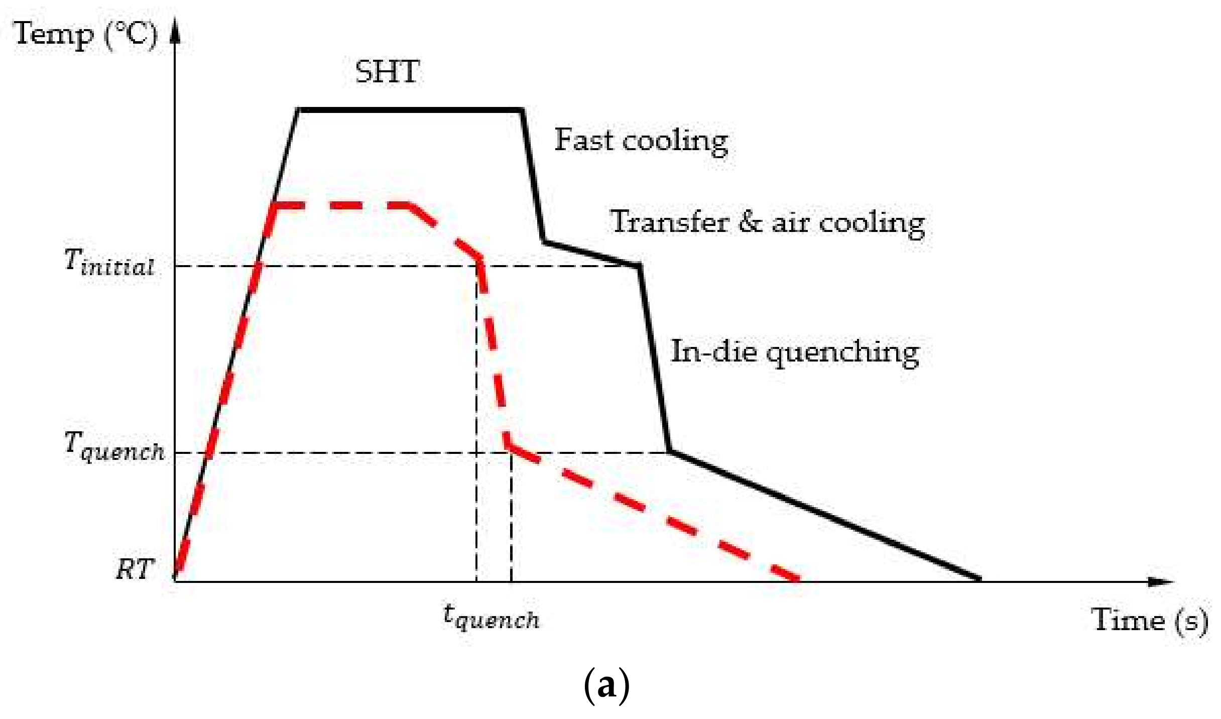
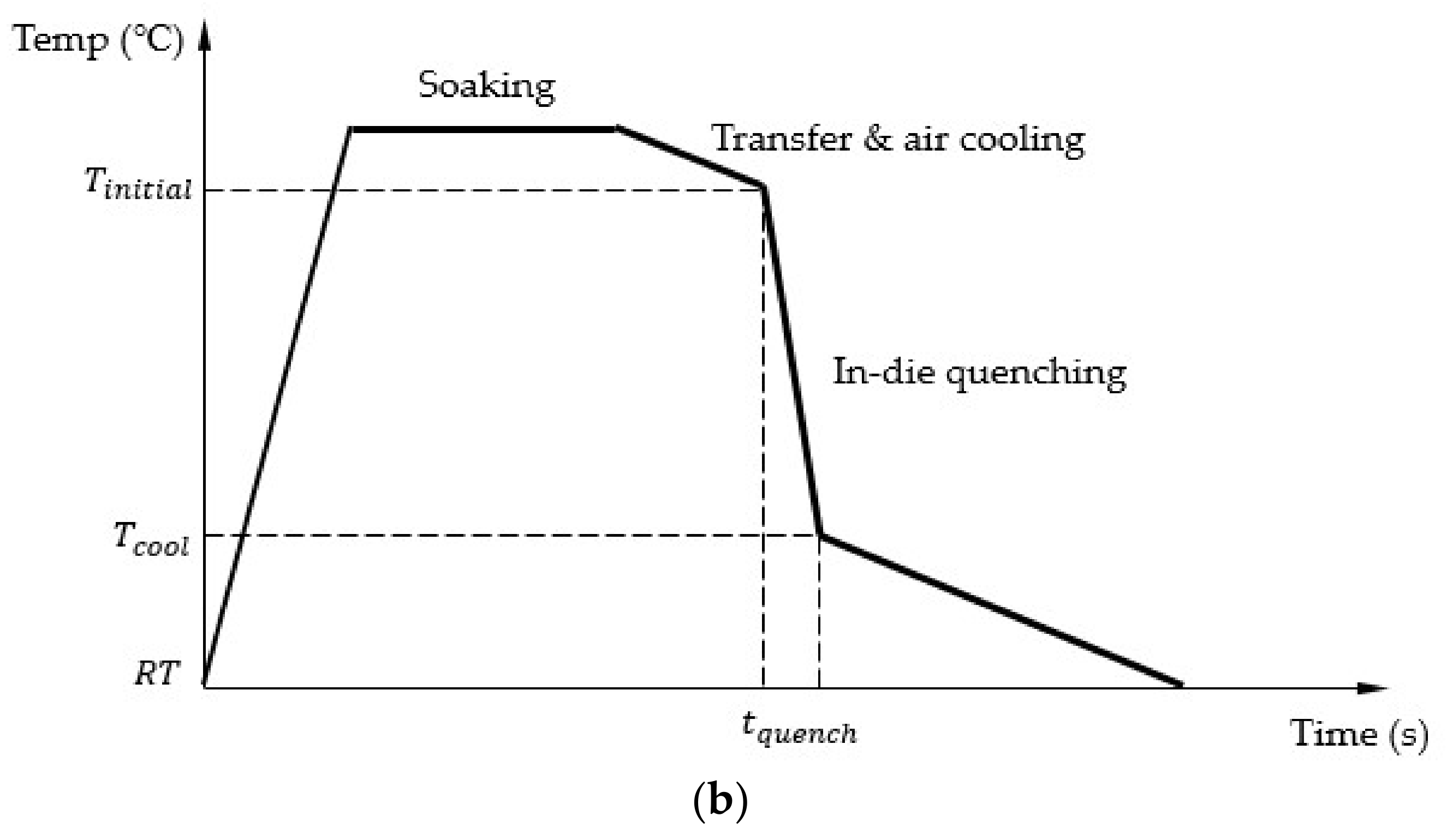
Figure 3a illustrates the temperature profiles used to assess the in-die quenching under the HFQ® technology forming conditions (solid line). In order to achieve different temperatures before in-die quenching, a fast intermediate-cooling stage is preferably used, enabling the preservation of the obtained optimal microstructure during solution heat treatment (SHT) as disclosed in the patent WO2015136299. Due to difficulties in controlling the temperature during the experiments, a modified simple temperature profile, as indicated by the dashed line, was used in this study to replace the conventional HFQ® technology process in Figure 3b. The effects of material properties on the thermal response are assumed to be negligible. In this process, the as-received work-piece was heated to different temperatures, and soaked for 1 min to achieve a uniform temperature distribution. Then, the work-piece was transferred to the pins located on the lower die and air cooled to target temperatures. Subsequently, the ram of the press was activated to press the upper die at a speed of 300 mm/s to close the 15 mm gap between the upper and lower dies. The in-die quenching force was exerted by the counterforce of gas cushion system below the whole rig. The in-die quenching stage was completed, and the upper and lower dies were separated once the work-piece was quenched to designed temperatures that are lower than the artificial ageing temperature of AA6082 (190 °C). To quantify the in-die quenching efficiency, a term, tquench, equaling to the time of quenching the work-piece from an initial temperature Tinitial to a target quenched temperature Tquench, is used. These values need to be determined experimentally. Before each test, gas springs were charged to different pressures to provide different in-die quenching forces. The charged pressures were able to achieve different contact pressures as summarised in Table 2. In addition, the quenching dies were heated to different temperatures. During quenching, the temperatures of both the work-piece and the dies were continually recorded. Table 2 summarises the conditions of the in-die quenching tests.
Figure 3b shows the temperature profile of the conventional HFQ® process, which was used to investigate effects of die clearances on the in-die quenching performance. Initially, the work-piece was heated to 525 °C, and soaked for 2 min. Then, it was transferred to the quenching dies and in-die quenched with different clearances. The work-piece thickness was 2 mm. The values of clearance used were 0.1, 0.2, 0.5, and 1 mm for both single-sided and double-sided clearances. Before each test, a different number of steel foils were inserted. The accuracy of the clearance was controlled to within 0.02 mm.
3. Die Surface Temperature Calculation
Since the work-piece material flows at the interface between die surfaces, the die surface temperature evolution during hot stamping is crucial, which may affect the friction of tooling and lubrication, such as surface coating. In this study, a one-dimensional (1D) closed-form method was used to calculate the die surface temperatures under different process variables. The temperature evolution of an object can be calculated by the energy conservation equation, given by Equation (1). Due to the absence of mass transfer, thermal radiation and additional heat generated by plastic straining, these effects were neglected during the in-die quenching stage:
where T is the temperature, t is time, ρ is the density, k is the thermal conductivity, and cp is the thermal capacity. The heat transfer between the cold dies and the hot work-piece is simplified to a one-dimensional heat transfer condition, with heat flow along the thickness of the work-piece. The heat transfer in the radial direction was ignored because the central position of thermocouples results in the convection by the surrounding air being negligible. Based on this assumption, the differential equation in Equation (1) can be rewritten as below:
where x represents the position and:
To solve the partial differential equation, Equation (2), a finite difference method, the backward time-centred space difference scheme, described by Equation (4), was used:
where Δt is the time increment, Δx is the distance increment within work-piece or die. Ο is the truncation error. After neglecting the higher-order truncation errors, Equation (4) can be recast as follows:
Then, a matrix of the temperature evolution is established from Equation (5):
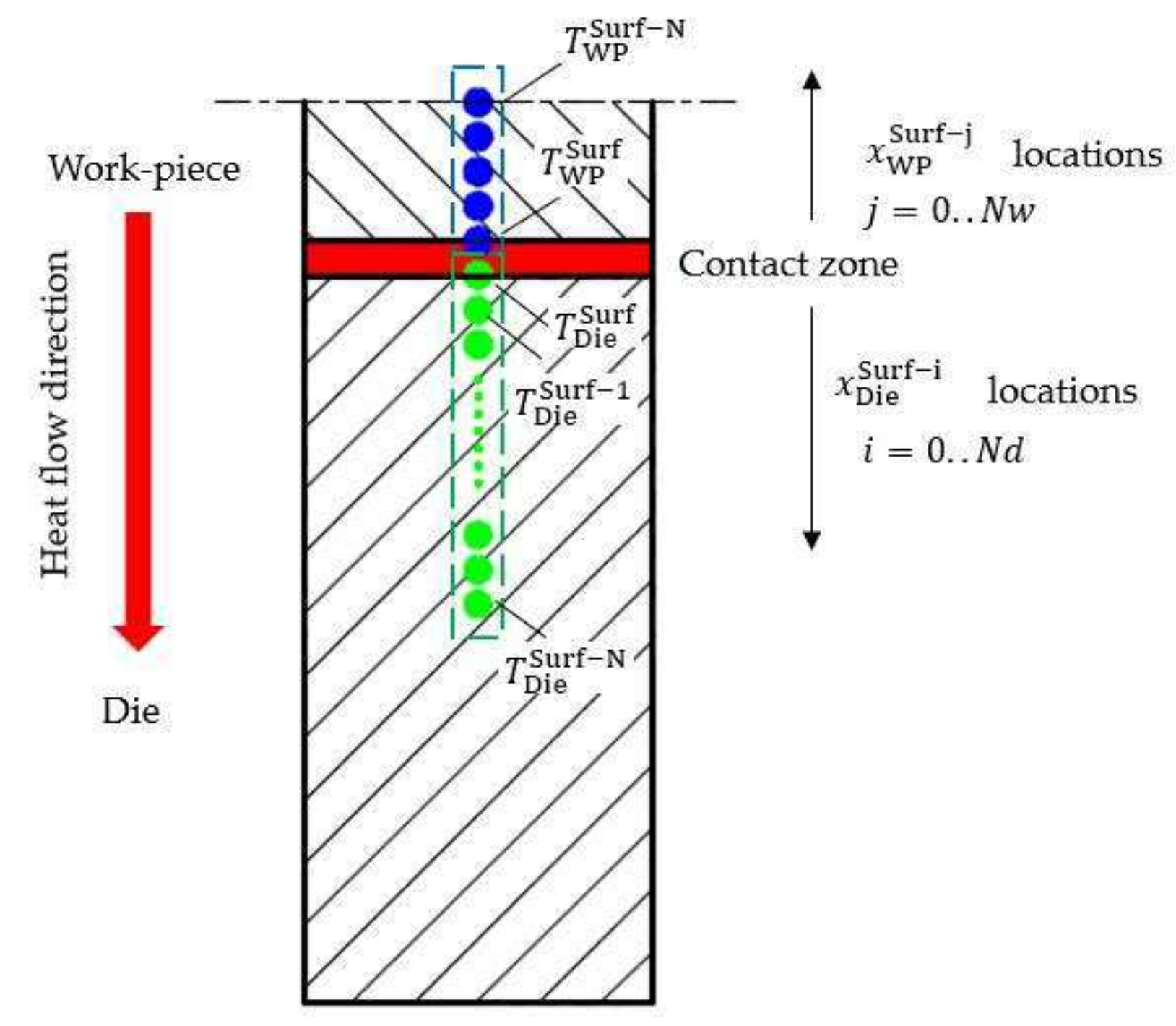
where the subscripts denote the node number, as shown in Figure 4. When x = 0, i = 0. The coefficients a, b, and c are defined as follows:
The temperature at each time step and location within the die can be calculated when the initial condition, T0 (initial die temperature), and are known. The initial die temperature was assumed to be uniform, i.e., 25 °C, 50 °C, 75 °C, and 100 °C. is the temperature of the die recorded from the 4 mm thermocouple. The die surface temperature, , which is the other boundary condition, was determined by first setting an initial guess of this value and then calculated by using the least-squares method to minimise the difference between calculated and measured temperatures at the other locations. The error function is given as:
where represents the experimentally-measured temperature of die location and represents the calculated temperature using the surface temperature that is set during the optimisation process. An optimisation algorithm was used to determine the die surface temperature so that the minimum error is obtained.
This procedure is then repeated for every time step. Lastly, the heat flux, , across the surface of the work-piece and die was calculated using the gradients at these surfaces, which is given by the following equation based on the finite difference scheme. This approach is similar to the one performed in [19]:
where the subscript denotes the point at the surface.
The effective heat transfer coefficient, h, is then calculated using the average heat flux of the surface of the die, , and work-piece, :
The work-piece temperature is calculated straightforwardly using Equation (6), and setting the boundary conditions to the appropriate values. The temperature at the surface of the work-piece was set to be that of the temperature measured by the thermocouples. The work-piece is assumed to be symmetrical, so the thermal gradient at the other end, which is the line of symmetry, is set to be zero.
4. Results and Discussion
4.1. Validation of 1D Closed Form Calculation Method
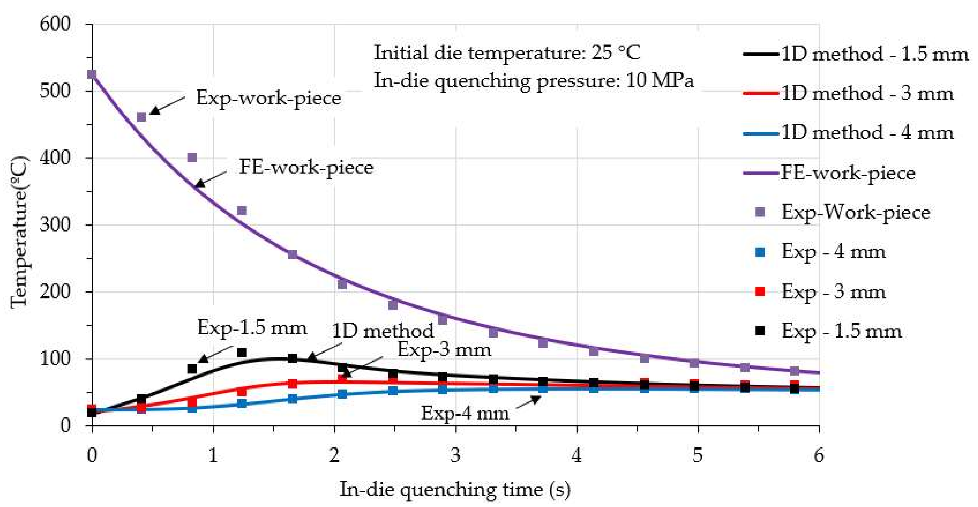
The 1D closed form calculations were verified by both the experimental results and finite element simulations. Figure 5 shows the comparison between experimental results of the in-die quenching test and the calculated results for the work-piece and die temperatures. The initial temperatures of work-piece and die were 525 °C and 25 °C, respectively. The interface contact pressure was 10 MPa. For the die, temperatures at three locations, which are 1.5 mm, 3 mm, and 4 mm from the die surface, were measured (solid symbols) and compared with the computational results (solid lines). As shown in Figure 5, in general, the computed results using the 1D closed-form model exhibit a good agreement with the experimentally-measured results. The characteristics of temperature evolutions of both the work-piece and die can be predicted. Initially, the temperature of the work-piece dropped drastically in the first 1.5 s, and the significant heat transferred from the work-piece to the die resulted in a temperature increase on the areas approaching die surface. Then, the work-piece temperature decreased gradually due to the small temperature gradient between the work-piece and die surface. Less heat was transferred to the die, subsequently, and the heat was further transferred from the die surface to the inner portions of the die, which enables the temperature near the die surface (1.5 mm) to decrease, and the temperature away from the die surface (4 mm) to increase gradually. In addition, the interface heat transfer coefficient was calculated and implemented into the finite element (FE) simulation model, Deform 2D, to predict the temperature history of work-piece and die surface temperature evolution, as performed in a previous study [17]. Good agreement is also observed for the work-piece between experimental and computed results, as shown in Figure 5, which validates the calculation of the 1D closed-form model.
4.2. In-Die Quenching Efficiency
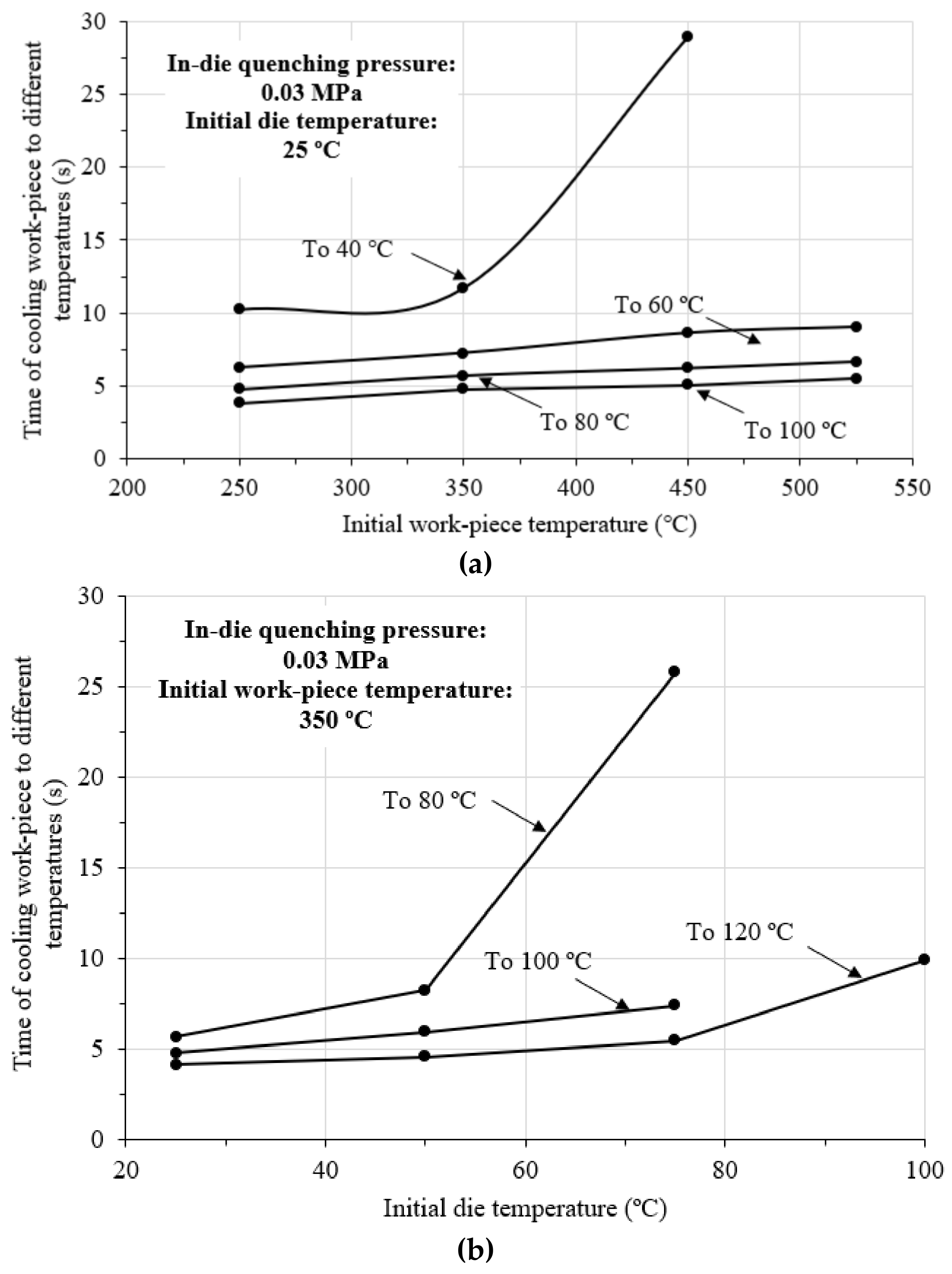
During the continuous volume production of hot stamping aluminium alloy components, the in-die quenching time (time of formed component held by stamping dies) is an important parameter that needs to be designed. This parameter determines the manufacturing efficiency and productivity. For the HFQ® forming of aluminium alloy parts, after hot stamping, the stamping dies are separated when the part temperature is quenched to a temperature that is lower than the artificial ageing temperature. Figure 6 shows the required time of cooling work-piece, tquench, to different temperatures, Tquench, with different initial work-piece and die temperatures. As seen in Figure 6a, the in-die quenching time increases significantly with decreasing Tquench, which is the work-piece temperature after in-die quenching. Furthermore, the time decreases with decreasing initial work-piece temperature. However, the reduction of this time is not obvious, unless Tquench is sufficiently low, such as 40 °C. Figure 6b shows variations of in-die quenching time of quenching the work-piece to different temperatures at different initial die temperatures, which the simulation of the effects of increased die temperature after a certain number of hot stamping cycles during mass production. To cool the work-piece to 80 °C, the in-die quenching time of the 75 °C die was severely increased to above 25 s compared to the 5 s of the die at 25 °C (room temperature). Therefore, the die temperature should be below 75 °C for the hot stamping of aluminium alloys.
4.3. Evolutions of Die Surface Temperature
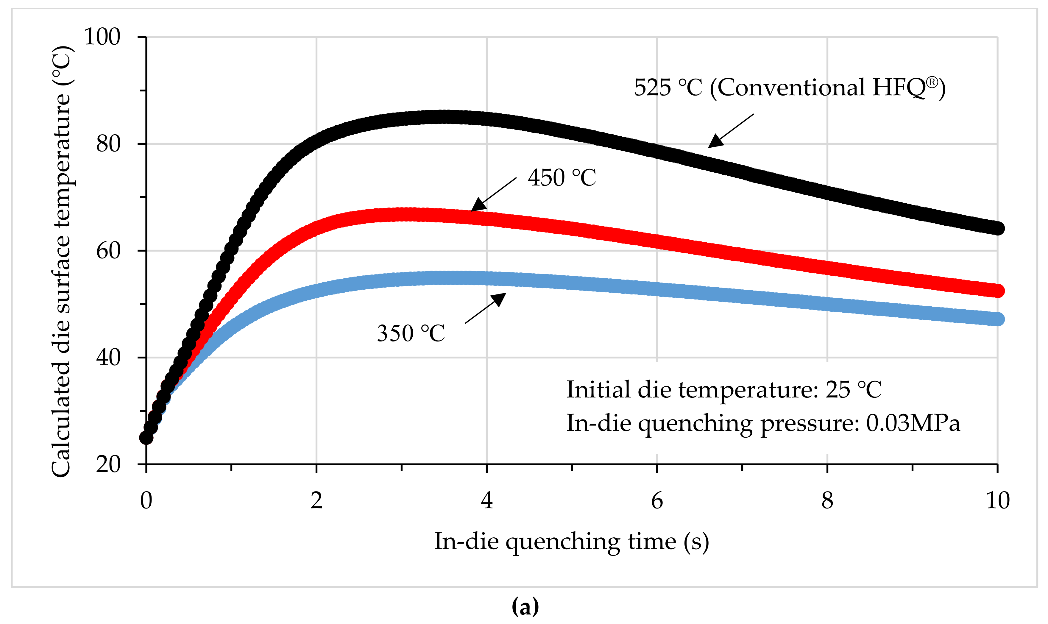
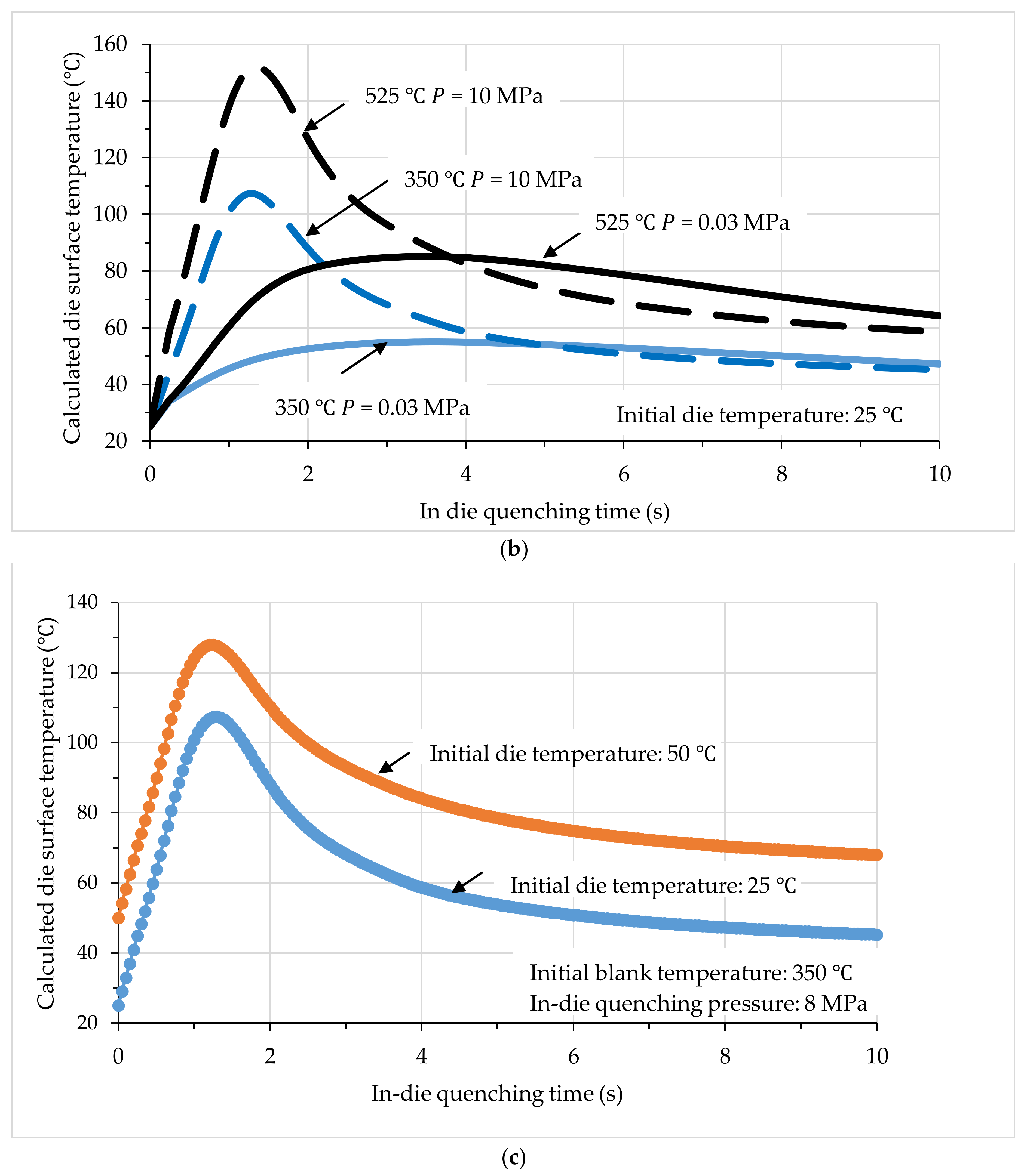
Figure 7 shows the calculated die temperature evolutions under different influencing factors. Figure 7a shows variations of die surface temperature with different initial work-piece temperatures. The initial die temperature was 25 °C, and the contact pressure was 0.03 MPa. With the decreasing initial work-piece temperature of in-die quenching, the die surface temperature decreases significantly, which indicates that forming at relatively lower temperatures, unlike forming using the conventional HFQ® technology, can cause the severe high-temperature condition of the die surface and contribute to reducing thermal fatigue and potentially extending the tool life. Additionally, a relatively lower interface temperature also results in lower friction, which is believed to be beneficial for flanged material flow. Figure 7b shows the contact pressure effect on the die surface temperature evolutions. At a high contact pressure of 10 MPa, the maximum die surface temperature increased greatly. For instance, for the conventional HFQ® process with a die temperature at room temperature. The maximum die surface temperature increased to 150 °C compared to the 85 °C of 0.03 MPa. Therefore, the blank-holding pressure is normally controlled not to be too high, to avoid the increase of the interface temperature and friction coefficient correspondingly. In addition, the profile of the die surface temperature evolution also varies with contact pressure. For high temperatures, the heat within the work-piece is transferred quickly to the die due to the high contact pressure, because of the greater deformation of surface asperities. This situation results in the die surface temperature increasing significantly at the early stage of in-die quenching. Then, the work-piece and die surface temperatures approached a steady state, and the heat transferred from the die surface to the inside regions of the die are now more than the input heat from the work-piece, resulting in a decrease of the die surface. In comparison, at a low contact pressure of 0.03 MPa, the temperature of the die surface increased gradually due to the slower heat input from the work-piece. Correspondingly, the quenching rate of the work-piece was lower. Therefore, using a die material with high thermal conductivity is beneficial to the in-die quenching efficiency, combined with using a contact pressure, the heat at the die surface is able to be immediately transferred into the die, resulting in high quenching rates and less die surface temperature effects. Figure 7c shows the die surface temperature evolutions of different initial temperatures. The contact pressure used was 8 MPa, which is similar to Figure 7b. The evolution trends are similar for different temperatures, which can be regarded as an offset with the magnitude of the initial die temperature.
4.4. Effects of Contact Pressure
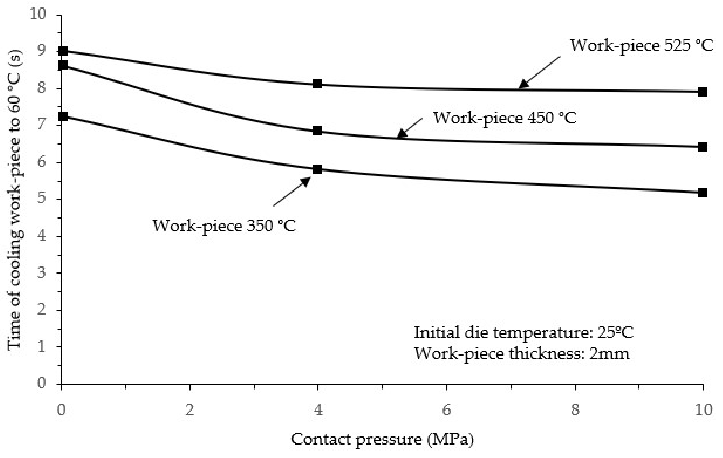
The interfacial heat transfer coefficient is dependent on the interface contact pressure, which determines the in-die quenching efficiency significantly. Figure 8 shows effects of contact pressure on the in-die quenching time when Tquench equals to 100 °C with different initial work-piece temperatures. For a given initial work-piece temperature, by increasing the contact pressure to 4 Mpa, the required tquench is significantly reduced. However, the time cannot be further reduced by increasing the contact pressure. In addition, tquench also increases with increasing initial work-piece temperature at a given contact pressure. For a contact pressure of 4 MPa, the tquench with an initial work-piece temperature of 525 °C increases to 4.7 s, which is an approximately 56.7% increase compared to the 3 s using an initial work-piece temperature of 350 °C. This observation suggests that reducing the initial forming temperature of the HFQ® process contributes to an improved in-die quenching efficiency. The effects on the maximum die surface temperatures are shown in Figure 7b. For an initial work-piece temperature of 525 °C, the maximum die surface of 10 MPa was higher than that of 0.03 MPa. The reason for this observation is that the interfacial heat transfer increases with contact pressure, resulting in more heat being transferred to the die material (regions approaching the surface) and had no time to be further be transferred within the die material during the early stage of quenching. Therefore, the die surface temperature increased quickly and significantly. A greater maximum die surface temperature was obtained using a higher contact pressure.
4.5. Effects of Die Temperature
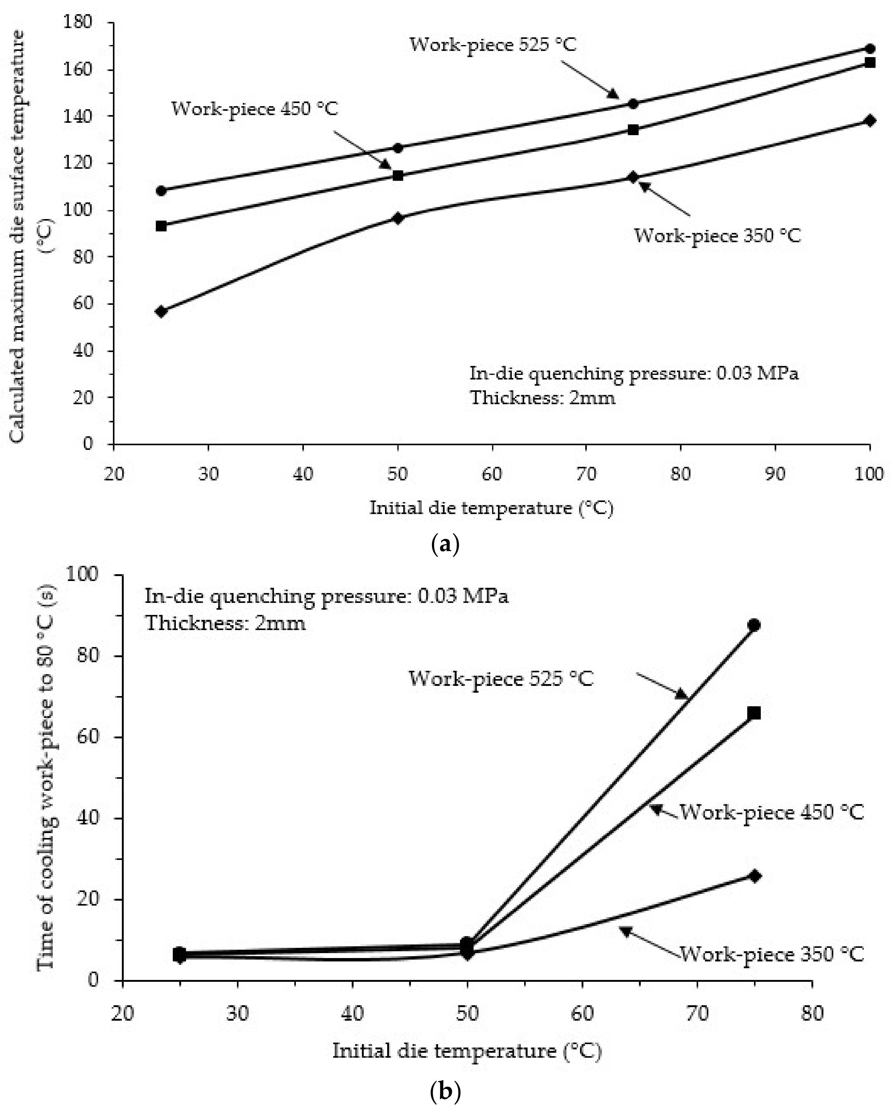
After several hot stamping cycles, the die surface temperature will rise due to heat being transferred from the hot work-piece to the stamping dies. The increase of die surface temperature might cause the in-die quenching rate to vary and increases tquench significantly. Figure 9 shows the effects of the increase in die temperature on the maximum die surface temperature and subsequent in-die quenching efficiency. As shown in Figure 9a, with the increasing die temperature, the calculated maximum die surface temperature increases severely. For an initial work-piece temperature of 450 °C, the maximum die surface temperature increases from 56.8 °C to 113.8 °C, when the temperature of die increases from room temperature to 100 °C. Such a temperature increase of the die surface results in a decrease in the interface temperature gradient, which reduces the quenching rate (Equation (1)), and the work-piece may not be able to be further cooled when the temperatures of die surface and work-piece become similar. As verified in Figure 9b, for example, the time to cool the work-piece to 80 °C increases to 25.8 s for the die at 75 °C and an initial work-piece temperature of 350 °C, which is believed to be unacceptable for continuous volume production of hot stamping aluminium alloys. In addition, it is interesting to find that the effects of initial work-piece temperature are not obvious when the die temperature is controlled below 50 °C. The reason for this observation is believed to be that, once Tquench equals 80 °C, the temperature gradient can still guarantee a sufficiently high cooling rate before quenching the work-piece to 80 °C. Therefore, for a practical hot stamping production line, the maximum acceptable die temperature (before water cooling dies) is dependent on the design of Tquench according to the age hardening performance of the specific alloy.
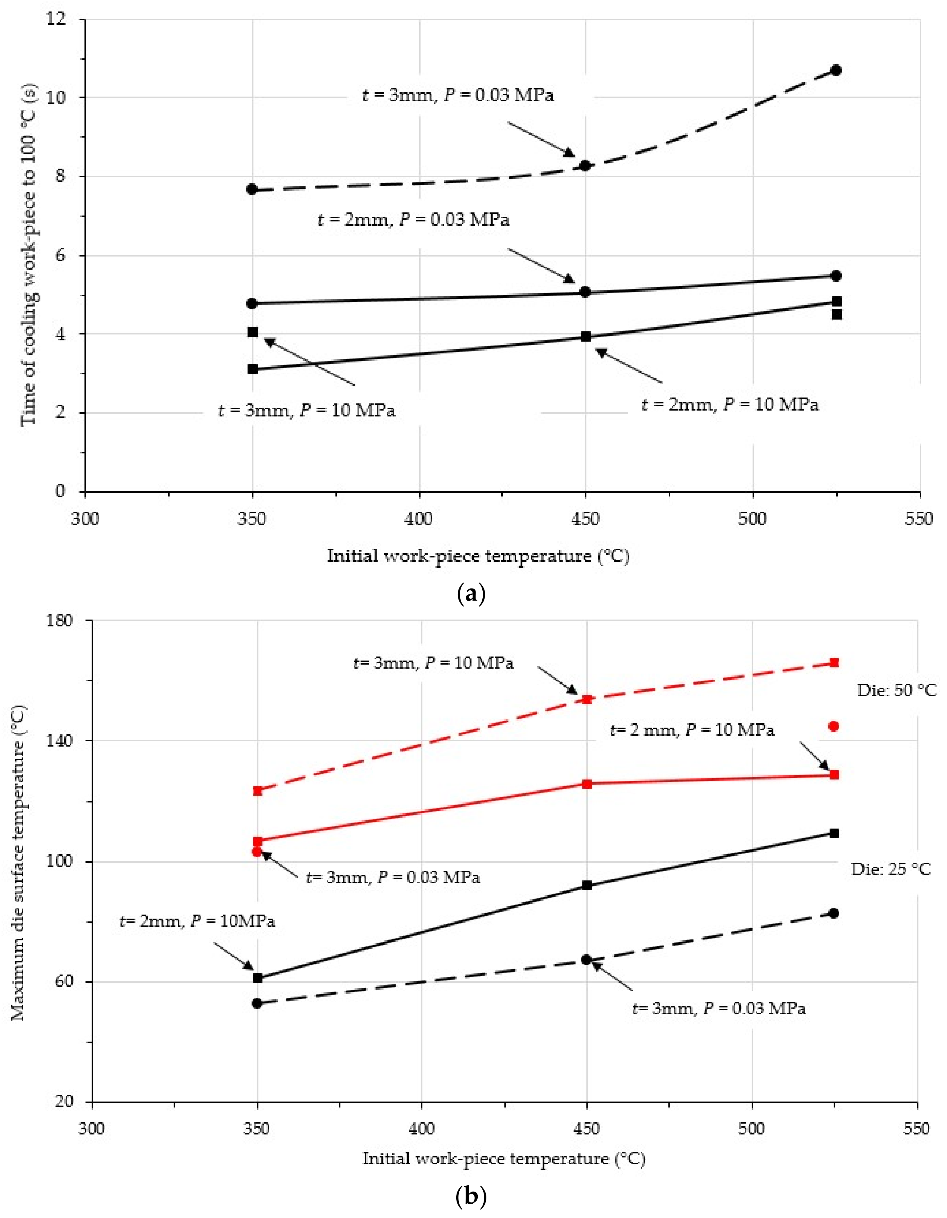
4.6. Effect of Work-Piece Thickness
Figure 10 shows the effect of work-piece thickness on the in-die quenching performance. Figure 10a shows the in-die quenching efficiency, and Figure 10b shows the calculated maximum die surface temperature. As seen in Figure 10a, the thickness plays an important role in determining the in-die quenching time. For an initial work-piece temperature of 450 °C and contact pressure of 0.03 MPa, tquench increases from 5 s for a thickness of 2 mm to 8.1 s for a thickness of 3 mm, which is a 62% increase of time. This indicates that a greater contact pressure is required to guarantee the efficiency of in-die quenching for thicker work-pieces. By increasing the contact pressure to 10 MPa for the 3 mm work-piece with an initial temperature of 525 °C (conventional HFQ® Technology), tquench decreased from 10.5 s to 4.4 s, which is an approximately 58.1% savings in time. In addition, under a certain contact pressure, tquench can be reduced by decreasing the work-piece temperature, as discussed above. For a 3 mm thick work-piece, the required tquench is 4 s for an initial work-piece temperature of 350 °C, while it is 3.1 s for a 2 mm thick work-piece. In general, the thicker the work-piece, the more heat is stored within the work-piece, and the die surface temperature becomes higher because of the corresponding heat transfer, as shown in Figure 10b. For an initial die temperature of 50 °C and work-piece temperature of 525 °C, the maximum die surface temperature increased from 128.8 °C to 165.9 °C with increasing work-piece thickness from 2 mm to 3 mm at a contact pressure of 10 MPa. For a work-piece with an initial temperature of 350 °C, the maximum die surface temperature of the 3 mm workpiece at 0.03 MPa contact pressure, is similar to that of the 2 mm work-piece at 10 MPa contact pressure. On the other hand, the temperature of the 3 mm work-piece at 0.03 MPa contact pressure is higher than that of the 2 mm work-piece at 10 MPa contact pressure. This indicates that the effect of work-piece thickness should be considered in addition to the initial work-piece temperature, which is only obvious for high initial work-piece temperatures. Otherwise, the contact pressure plays a dominant role.
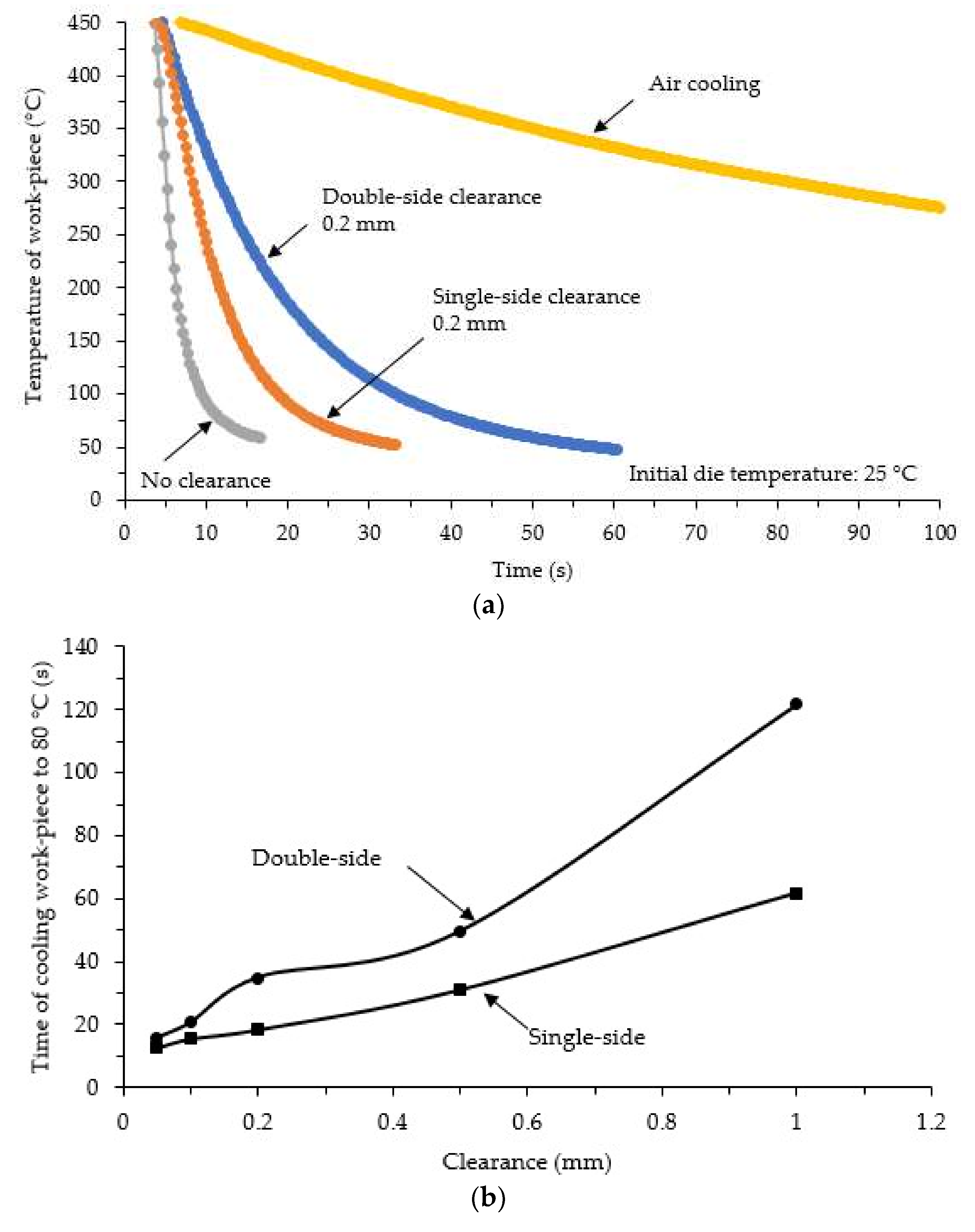
4.7. Effect of Die Clearance
The clearance is an important feature for hot stamping aluminium alloys due to several factors. Firstly, thinning is normally observed on a complex-shaped formed component, which results in gaps between the sheet and tools, and the contact is between the component and die is incomplete. Secondly, there is always a clearance between the punch and the die, approximately 0.1 mm of sheet thickness, which may induce one-sided or double-sided clearances. At locations where such a clearance is present, the heat transfer between the hot work-piece to the cold dies changes to that between the hot work-piece and the air. The work-piece at these local areas is preferably cooled by the thermal conduction within work-piece, and the quenching rate might not be guaranteed, resulting in potentially lower post-formed strength, especially for high quench-sensitive aluminium alloys, such as high-strength AA7075 and AA7050, that are popular candidates for automotive use. Figure 11a shows the effects of clearance on the in-die quenching of the work-piece. The clearance used was 0.2 mm, and the initial die and work-piece temperatures are 25 °C and 450 °C, respectively. As observed in this figure, the clearance reduced the quenching rate severely. Quenching with a single-sided clearance is quicker than a double-sided clearance, as there is still a slight heat convection between the work-piece and the cold die on one side. Although quenching with double-sided clearance is similar to the scenario of air cooling, the quenching rate is still higher than that of air cooling, which is believed to be caused by the heated hot air around the work-piece being transferred to cold dies. Figure 11b shows the summarised variations tquench of quenching the work-piece to 80 °C with different clearance values. The clearance, either single-sided or double-sided, severely increased tquench. Apart from the initial design of the tool setup, improving the uniformity of deformation to obtain a more uniform thickness within the formed component is also critical to reducing the clearance effects.
5. Conclusions
The presented study comprehensively investigated the key influencing factors of the in-die quenching stage of hot stamping aluminium alloys experimentally and theoretically. The performed in-die quenching tests and 1D closed-form heat transfer calculations enable the effects of initial work-piece and die temperatures, contact pressure, work-piece thickness, and clearances on the in-die quenching performance to be understood thoroughly. The following conclusions are drawn:
(1) The in-die quenching efficiency is significantly increased with decreasing initial work-piece and die temperatures and work-piece thickness;
(2) Contact pressure is the dominant parameter that determines the time of quenching and die surface temperature evolutions;
(3) The clearance of tools severely deteriorate in-die quenching performance, so precise tool design and improving the uniformity of deformation are potential solutions to address the clearance effect. In addition, the experimentally-measured and analytically-calculated data aids tooling design and thermal surface engineering treatments by providing reasonable evaluations.
Acknowledgments
The research in this paper was funded by the European Union’s Horizon 2020 research and innovation programme under grant agreement No. H2020-NMBP-GV-2016 (723517) as part of the project “Low-Cost Materials Processing Technologies for Mass Production of Lightweight Vehicles (LoCoMaTech)”. HFQ® is a registered trademark of Impression Technologies Limited. Impression Technologies Limited is the sole licensee for the commercialisation of the HFQ® technology from Imperial College London.
Author Contributions
Kailun Zheng and Jianguo Lin conceived and designed the experiments; Kailun Zheng and Junyi Lee performed the development of the mathematical model; Kailun Zheng and Wenchao Xiao performed the experiments; and Baoyu Wang contributed materials and tool design and machining. Kailun Zheng and Junyi Lee contributed to writing this paper. All authors contributed to analyzing the data.
Conflicts of Interest
The authors declare no conflict of interest.
References
- León, J.; Luis, J.C.; Fuertes, P.J.; Puertas, I.; Luri, R.; Salcedo, D. A proposal of a constitutive description for aluminium alloys in both cold and hot working. Metals 2016, 6, 244. [Google Scholar] [CrossRef]
- Zhang, S.; Chen, T.; Zhou, J.; Xiu, D.; Li, T.; Cheng, K. Mechanical properties of thixoforged in situ Mg2Sip/AM60B composite at elevated temperatures. Metals 2018, 8, 106. [Google Scholar] [CrossRef]
- El Fakir, O.; Wang, L.; Balint, D.; Dear, J.P.; Lin, J.; Dean, T.A. Numerical study of the solution heat treatment, forming, and in-die quenching (HFQ) process on AA5754. Int. J. Mach. Tools Manuf. 2014, 87, 39–48. [Google Scholar] [CrossRef]
- Zheng, K.; Lee, J.; Lin, J.; Dean, T.A. A buckling model for flange wrinkling in hot deep drawing aluminium alloys with macro-textured tool surfaces. Int. J. Mach. Tools Manuf. 2017, 114, 21–34. [Google Scholar] [CrossRef]
- Nishibata, T.; Kojima, N. Effect of quenching rate on hardness and microstructure of hot-stamped steel. J. Alloys Compd. 2013, 577, S549–S554. [Google Scholar] [CrossRef]
- Sjöström, J.; Bergström, J. Thermal fatigue in hot-working tools. Scand. J. Metall. 2005, 34, 221–231. [Google Scholar] [CrossRef]
- Maeno, T.; Mori, K.I.; Fujimoto, M. Improvements in productivity and formability by water and die quenching in hot stamping of ultra-high strength steel parts. CIRP Ann. Manuf. Technol. 2015, 64, 281–284. [Google Scholar] [CrossRef]
- Cortina, M.; Arrizubieta, I.J.; Calleja, A.; Ukar, E.; Alberdi, A. Case study to illustrate the potential of conformal cooling channels for hot stamping dies manufactured using hybrid process of laser metal deposition (LMD) and milling. Metals 2018, 8, 102. [Google Scholar] [CrossRef]
- Abdollahpoor, A.; Chen, X.; Pereira, M.P.; Xiao, N.; Rolfe, B.F. Sensitivity of the final properties of tailored hot stamping components to the process and material parameters. J. Mater. Process. Technol. 2016, 228, 125–136. [Google Scholar] [CrossRef]
- Mendiguren, J.; Ortubay, R.; De Argandonã, E.S.; Galdos, L. Experimental characterization of the heat transfer coefficient under different close loop controlled pressures and die temperatures. Appl. Therm. Eng. 2016, 99, 813–824. [Google Scholar] [CrossRef]
- Li, H.; He, L.; Zhang, C.; Cui, H. Research on the effect of boundary pressure on the boundary heat transfer coefficients between hot stamping die and boron steel. Int. J. Heat Mass Transf. 2015, 91, 401–415. [Google Scholar] [CrossRef]
- Chang, Y.; Tang, X.; Zhao, K.; Hu, P.; Wu, Y. Investigation of the factors influencing the interfacial heat transfer coefficient in hot stamping. J. Mater. Process. Technol. 2016, 228, 25–33. [Google Scholar] [CrossRef]
- Liu, X.; Fakir, O.; El Meng, L.; Sun, X.; Li, X.; Wang, L. Effects of lubricant on the IHTC during the hot stamping of AA6082 aluminium alloy: Experimental and modelling studies. J. Mater. Process. Technol. 2018, 255, 175–183. [Google Scholar] [CrossRef]
- Hu, P.; Ying, L.; Li, Y.; Liao, Z. Effect of oxide scale on temperature-dependent interfacial heat transfer in hot stamping process. J. Mater. Process. Technol. 2013, 213, 1475–1483. [Google Scholar] [CrossRef]
- Merklein, M.; Lechler, J.; Stoehr, T. Investigations on the thermal behavior of ultra high strength boron manganese steels within hot stamping. Int. J. Mater. Form. 2009, 2, 259. [Google Scholar] [CrossRef]
- Ying, L.; Gao, T.; Dai, M.; Hu, P. Investigation of interfacial heat transfer mechanism for 7075-T6 aluminum alloy in HFQ hot forming process. Appl. Therm. Eng. 2017, 118, 266–282. [Google Scholar] [CrossRef]
- Xiao, W.; Wang, B.; Zheng, K.; Zhou, J.; Lin, J. A study of interfacial heat transfer and its effect on quenching when hot stamping AA7075. Arch. Civ. Mech. Eng. 2018, 18, 723–730. [Google Scholar] [CrossRef]
- Liu, X.; Ji, K.; Fakir, O.; El Fang, H.; Gharbi, M.M.; Wang, L. Determination of the interfacial heat transfer coefficient for a hot aluminium stamping process. J. Mater. Process. Technol. 2017, 247, 158–170. [Google Scholar] [CrossRef]
- Bai, Q.; Lin, J.; Zhan, L.; Dean, T.A.; Balint, D.S.; Zhang, Z. An efficient closed-form method for determining interfacial heat transfer coefficient in metal forming. Int. J. Mach. Tools Manuf. 2012, 56, 102–110. [Google Scholar] [CrossRef]
Figure 1.
Thermocouple layout in the blank to measure the blank (100 mm diameter and 2 mm thick) temperature at different positions (all dimensions are in mm).
Figure 1.
Thermocouple layout in the blank to measure the blank (100 mm diameter and 2 mm thick) temperature at different positions (all dimensions are in mm).

Figure 2.
Experimental set-up of in-die quenching: (a) test rig dimensions (all dimensions are in mm); (b) in-die quenching test rig; and (c) schematic of die clearance designs.
Figure 2.
Experimental set-up of in-die quenching: (a) test rig dimensions (all dimensions are in mm); (b) in-die quenching test rig; and (c) schematic of die clearance designs.


Figure 3.
Temperature profile of work-piece during in-die quenching process: (a) HFQ® technology for lower temperatures (solid line) and alternative process (dash line); and (b) conventional forming using HFQ® technology.
Figure 3.
Temperature profile of work-piece during in-die quenching process: (a) HFQ® technology for lower temperatures (solid line) and alternative process (dash line); and (b) conventional forming using HFQ® technology.


Figure 4.
Simplified 1D heat transfer finite difference method for the work-piece and die with different initial temperatures.
Figure 4.
Simplified 1D heat transfer finite difference method for the work-piece and die with different initial temperatures.

Figure 5.
Validation of 1D closed-form method and FE simulation, where solid symbols represent experimentations, and solid lines represent calculation and computational results. The blank thickness was 3 mm.
Figure 5.
Validation of 1D closed-form method and FE simulation, where solid symbols represent experimentations, and solid lines represent calculation and computational results. The blank thickness was 3 mm.

Figure 6.
Effects of initial blank and die temperatures on the in-die quenching time of cooling work-piece to different temperatures at an in-die quenching pressure 0.03 MPa. The work-piece thickness was 2 mm. (a) Different initial work-piece temperatures; and (b) different initial die temperature.
Figure 6.
Effects of initial blank and die temperatures on the in-die quenching time of cooling work-piece to different temperatures at an in-die quenching pressure 0.03 MPa. The work-piece thickness was 2 mm. (a) Different initial work-piece temperatures; and (b) different initial die temperature.

Figure 7.
Calculated die surface temperatures at different process conditions during in-die quenching. The work-piece thickness was 3 mm. (a) Different initial work-piece temperature; (b) different contact pressure; and (c) different initial die temperatures.
Figure 7.
Calculated die surface temperatures at different process conditions during in-die quenching. The work-piece thickness was 3 mm. (a) Different initial work-piece temperature; (b) different contact pressure; and (c) different initial die temperatures.


Figure 8.
Effects of in-die quenching pressure on the in-die quenching efficiency. The initial die temperature was 25 °C. The work-piece thickness was 2 mm.
Figure 8.
Effects of in-die quenching pressure on the in-die quenching efficiency. The initial die temperature was 25 °C. The work-piece thickness was 2 mm.

Figure 9.
Effects of initial die temperature on the in-die quenching performance. The work-piece thickness was 2 mm. (a) Calculated maximum die surface temperature and (b) time of cooling work-piece to 80 °C.
Figure 9.
Effects of initial die temperature on the in-die quenching performance. The work-piece thickness was 2 mm. (a) Calculated maximum die surface temperature and (b) time of cooling work-piece to 80 °C.

Figure 10.
Effects of work-piece thickness on the in-die quenching performance, where the solid lines represent the 2 mm work-piece and the dash lines represent the 3 mm work-piece: (a) Time of cooling work-piece to 100 °C and (b) calculated maximum die surface temperature.
Figure 10.
Effects of work-piece thickness on the in-die quenching performance, where the solid lines represent the 2 mm work-piece and the dash lines represent the 3 mm work-piece: (a) Time of cooling work-piece to 100 °C and (b) calculated maximum die surface temperature.

Figure 11.
Effects of die clearance on (a) cooling of work-piece and (b) in-die quenching efficiency.
Figure 11.
Effects of die clearance on (a) cooling of work-piece and (b) in-die quenching efficiency.


Table 1.
Main chemical composition of AA6082.
| Element wt % | Mg | Si | Mn | Fe | Cu | Zn | Ti | Cr | Remainder |
|---|---|---|---|---|---|---|---|---|---|
| Min. | 0.6 | 0.7 | 0.4 | - | - | - | - | - | Al |
| Max. | 1.2 | 1.3 | 1 | 0.5 | 0.1 | 0.2 | 0.1 | 0.25 |
Table 2.
Test matrix of in-die quenching efficiency test.
| Work-Piece Temperature (°C) | Work-Piece Thickness (mm) | Die Temperature (°C) | Contact Pressure (MPa) |
|---|---|---|---|
| 250, 350, 450, 525 | 2, 3 | 25, 50, 75, 100 | 0.03, 1, 10 |
© 2018 by the authors. Licensee MDPI, Basel, Switzerland. This article is an open access article distributed under the terms and conditions of the Creative Commons Attribution (CC BY) license (http://creativecommons.org/licenses/by/4.0/).
Share and Cite
MDPI and ACS Style
Zheng, K.; Lee, J.; Xiao, W.; Wang, B.; Lin, J. Experimental Investigations of the In-Die Quenching Efficiency and Die Surface Temperature of Hot Stamping Aluminium Alloys. Metals 2018, 8, 231. https://doi.org/10.3390/met8040231
AMA Style
Zheng K, Lee J, Xiao W, Wang B, Lin J. Experimental Investigations of the In-Die Quenching Efficiency and Die Surface Temperature of Hot Stamping Aluminium Alloys. Metals. 2018; 8(4):231. https://doi.org/10.3390/met8040231
Chicago/Turabian StyleZheng, Kailun, Junyi Lee, Wenchao Xiao, Baoyu Wang, and Jianguo Lin. 2018. "Experimental Investigations of the In-Die Quenching Efficiency and Die Surface Temperature of Hot Stamping Aluminium Alloys" Metals 8, no. 4: 231. https://doi.org/10.3390/met8040231
Note that from the first issue of 2016, this journal uses article numbers instead of page numbers. See further details here.