Article

Influence of Alloys Position, Rolling and Welding Directions on Properties of AA2024/AA7050 Dissimilar Butt Weld Obtained by Friction Stir Welding

by
Alessandro Barbini
*,
Jan Carstensen
and
Jorge F. Dos Santos
Helmholtz-Zentrum Geesthacht, Institute of Materials Research, Materials Mechanics, Solid-State Joining Processes (WMP), 21502 Geesthacht, Germany
*
Author to whom correspondence should be addressed.
Metals 2018, 8(4), 202; https://doi.org/10.3390/met8040202
Submission received: 26 February 2018 / Revised: 14 March 2018 / Accepted: 19 March 2018 / Published: 22 March 2018
(This article belongs to the Special Issue Friction Stir Welding and Processing in Alloy Manufacturing)

Abstract

:
Friction stir welding (FSW) was carried out for the butt joining of dissimilar AA2024-T3 and AA7050-T7651 aluminium alloys with 2-mm thicknesses. A comparison between the position and orientation of different materials was performed by varying the welding speed while keeping the rotational speed constant. Through an analysis of the force and torque produced during welding and a simple analytical model, the results indicate that the heat input was reduced when the AA7050 alloy was located in the advancing side (AS) of the joint. The different material positions influenced the material transportation and the interface in the centre of the stir zone (SZ). The microhardness of both materials was lower when they were in the AS of the joint. The differences in the hardness values were reduced at higher welding speeds when the heat input was decreased. The mechanical performance increased when the lower strength alloy was located in the AS. The material orientation exhibited a small influence when the AA7050 alloy was in the AS and in general on the resulting microhardness for all the cases analysed. The tensile strength values were very similar for both orientations, but an increase in the yield strength could be measured when the materials were oriented in the transverse direction.

Graphical Abstract

1. Introduction

In aeronautical structures, the joining throw riveting or adhesive bonding of dissimilar materials is a common practice, which is necessary to increase the mechanical performance of machines [1,2]. The problems associated with these types of joining techniques, which are well known and widely used, are related mainly to the increase in weight, the high costs of the assembly and spare parts and the difficulty in the development of an efficient automatic process for the installation.
Friction stir welding (FSW), since its invention in the 1991 at The Welding Institute (TWI Ltd., Cambridge, UK) [3], has been seen as a competitive technique for joining dissimilar materials with a good consistency in mechanical properties at a high productivity. Currently, reviews were written regarding FSW with an overview regarding process development, the influence of different tool geometries, the generated microstructure and the resulting mechanical properties [4,5].
Dissimilar welds of AA6061 and AA7075 obtained by FSW have been previously studied [6], focusing on the processing parameters and the position of the materials. Dissimilar welding involving an aluminium 6XXX series alloy was investigated previously by Amancio-Filho et al. [7] without analysing the effects of the material position on the microstructure and the mechanical properties of the welds. Another study involving more traditional alloys for the aeronautical industry has been performed by Khodir and Shibayanagi [8] with AA2024 and AA7075.
In this study, the welding speed (WS) was relatively low with a maximum speed of 3.3 mm/s, which seems further from the possibility of an industrial application. Additionally, the same alloys were investigated in terms of material flow to achieve a better understanding of the mixing process [9]. Barbini et al. investigated the combination of materials presented here without considering the influence of the material positioning, and the study was focused on a comparison between FSW and a new variant called stationary shoulder FSW [10].
Studies regarding the behavior of butt-joints of AA7050 in different heat treatment conditions obtained by FSW were performed in the past [11,12,13]. These analyses focused on the influence of the weld on the precipitation evolution of the different areas developed during the process and the resulting mechanical properties. Similar analyses were performed in the case of AA2024 in T3 and T351 conditions [14,15,16]. The influence of process parameters on the temperature profiles and the mechanical properties were investigated as well for this alloy [17]. The important role played by the rotational speed in order to favor an adequate material flow and achieve sound joints without defects was highlighted.
The general conclusion of these works is that, due to the heat generated during the process and the temperature profile experienced, for both materials, precipitate transformation was observed and coarsening in the different zones generated after welding that influenced both local and global mechanical properties of the joints.
In the present study, the influence of the process parameters and the material position of dissimilar AA2024-T3 and AA7050-T7651 were studied in terms of the microstructure and mechanical properties. The influence of the process parameters was investigated by varying the transverse speed between 3 and 8 mm/s and maintaining a constant rotational speed of 600 rpm. A variation in the welding speed influenced the heat input of the process, according to the torque-based model proposed by Khandkar et al. [18]. Two separate analyses were performed to understand the influence of the variation in the material position and orientation. The two materials were firstly switched between the advancing and retreating side of the joint to understand the effect of different compositions on the joint properties, and then the orientation of the materials and the rolling direction with respect to the welding direction was changed (Figure 1).
The aim of this study was to obtain a solid base of data that could be used in future studies regarding the dissimilar welds of these types of aluminium alloys and explain how all the variables involved in the process can influence the mechanical properties of the joints.

2. Experimental Procedure

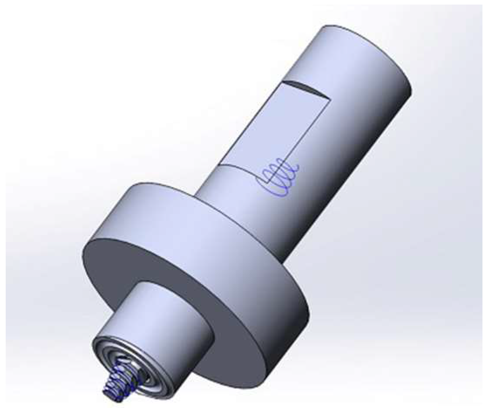
2.1. Base Materials and Welding Conditions

The two base materials, AA2024-T3 and AA7050-T7651, were cut in sheets of 300 × 150 mm with a thickness equal to 2 mm. The typical chemical composition of the two alloys was reviewed by Dursun et al. in the study regarding the most common materials used in the aerospace industry [19]. The aluminium 2024-T3 alloy is one of the most used materials in fuselage construction due to its high strength and excellent fatigue resistance. The mechanical properties of this alloy were measured in order to compare them with the results obtained after welding and they can be found in Table 1.
AA7050 is usually produced in thick plates or extrudes and is used in the aircraft industry for the realisation of fuselage stringers and wing panels. The mechanical properties of AA7050-T7651 were also measured and are listed in Table 2.
The welds were performed in the longitudinal direction with an FSW gantry machine. The tool used to perform the welds was formed by a flat shoulder of 13 mm of external diameter with a spiral profile and a conical probe with a diameter of 5 mm at the base and 3 mm at the top (Figure 2). The probe had a left-handed thread with three flat surfaces at the sides (Triflat). The material used for the entire tool is a high-performance molybdenum-vanadium alloyed hot-work tool steel (Hotvar). The welds were realised with force control, i.e., increasing the axial force while increasing the welding speed to obtain defect free joints.
In the experiment design, a rotational speed ( ω ) of 600 rpm and a tilt angle of 0° were kept constant and equal. The only process parameter that was changed was the welding speed, which modified the ratio between the rotational and welding speeds, commonly known as the pitch ratio, for each weld. The force parallel to the welding direction, called the welding force, and the torque measured during the process were recorded and used for the analysis of the process. The parameters involved in this research and the identification code of the welds are displayed in Table 3.

2.2. Characterisation Methods

The samples necessary to analyse the microstructure and hardness were cut orthogonally to the welding line with a length of 50 mm. For an investigation of the joints’ cross section, the samples were etched with Dix–Keller Reagent with an immersion time of 15 s after undergoing standard metallographic preparation.
The microhardness tests were performed on a Zwick/Roell ZHV machine (Ulm, Germany) with an applied load of 0.2 kgf for 10 s, in accordance with the standard ASTM E384-10. The line of indentation was positioned at the middle of the sample thickness, namely, 1 mm from the upper surface. The distance between the indentations was 0.5 mm, and the total length of the horizontal profile was 30 mm, symmetrical with respect to the weld centre (Figure 3).
A three-point bending test was performed to certify the quality of the joint immediately after the welding process. According to the standard ASTM E190-92, the diameter of the mandrel was 8 mm, and the distance between the supports was 15.2 mm. The specimens were tested in a Zwick/Roell universal testing machine with a load capacity of 100 kN. The test was stopped when the drop in the load reached 75% of the maximum force applied, and, in this way, all the specimens were tested under the same conditions. After the end of the test, the angle reached by the specimens was measured.
The tensile tests were performed orthogonally to the welding direction on the standard specimens with a 12.5 × 2 mm cross section on a Zwick/Roell universal testing machine with a load capacity of 100 kN. The strain was measured using a mechanical extensometer (MTS Systems GmbH, Berlin, Germany) with a gage length of 50 mm, positioned with its centre in the weld nugget. The tests were executed following the standard ASTM E8-09 at a room temperature of 22 °C with a constant transverse speed of 1 mm/min. For each welding condition, three specimens were used.
It is important to remark that, before proceeding with the mechanical tests, a period of more than 40 days was permitted to allow the process of natural ageing of the materials [11] and to ensure stable mechanical properties.

3. Results and Discussion

In the current study, all the characterisation methods and analyses were performed in a way to distinguish the effect of a different positioning of the materials from a different orientation. For this reason, firstly, the influence of the position of the material with respect to the weld line was analysed, and, subsequently, the influence of the orientation of the material was also analysed.

3.1. Position of the Materials

The first step was to investigate the influence of the materials position on the measured forces during the process and the consequent heat generation. After that, the resulting microstructure and material properties developed were analyzed in depth to have a clear understanding of the joint performance.

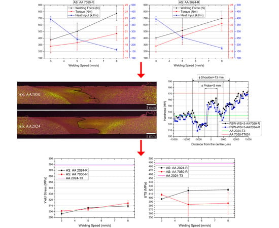
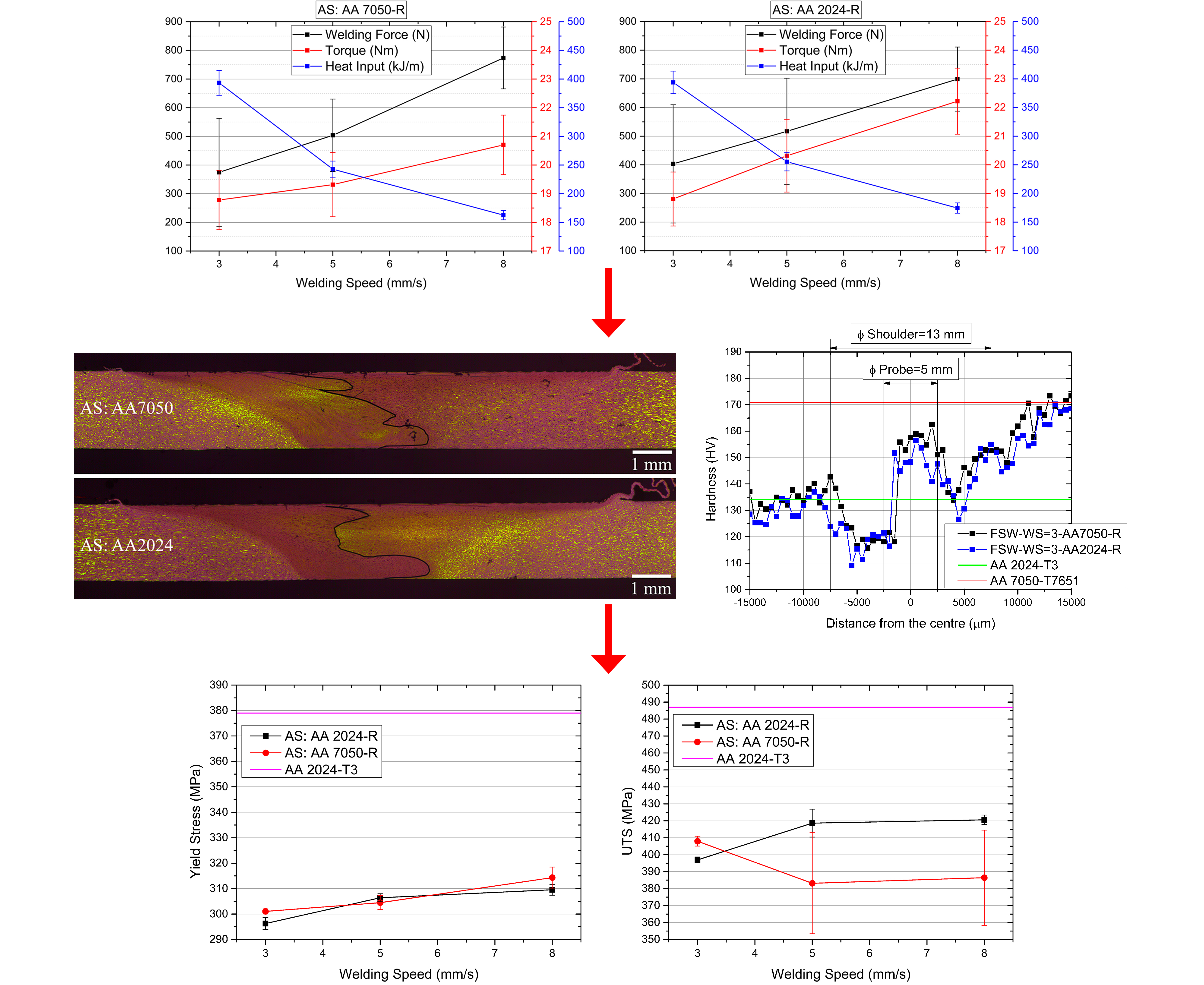
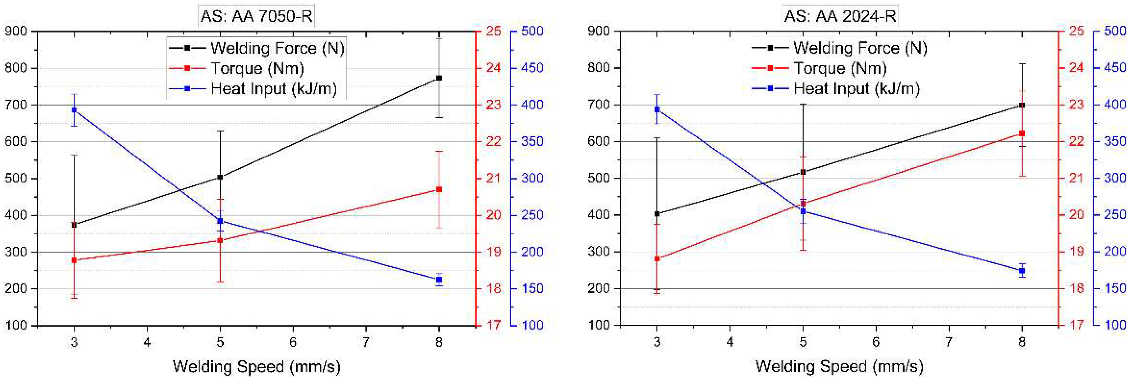
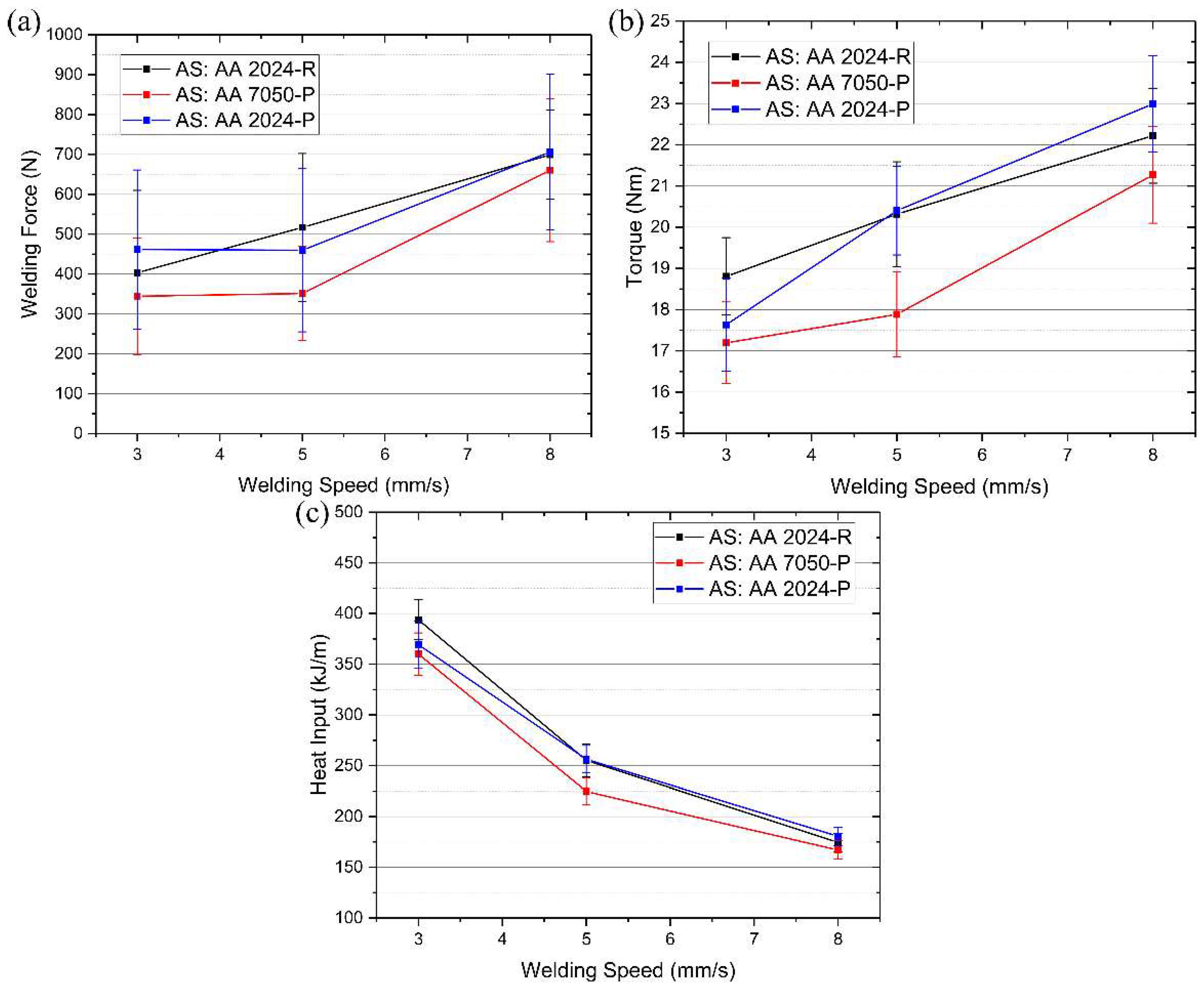
3.1.1. Process Analysis

The analysis of the process was based on the influence of a different material position on the welding force and torque measured during the process. Due to the asymmetric heat generation and material transportation between the (AS) and retreating side (RS) [20], it was expected that the difference in strength between the two materials would affect the two measured values.
When considering the welding force (Figure 4), note that, at the two lower welding speeds, the force on the tool is lower when the high-strength material is in the AS. The higher heat transferred in the AS causes a larger plasticisation of AA7050, reducing the global resistance of the material on the tool. This behaviour ceases at a higher welding speed, where the reduced heat transferred into the weld does possibly lead to an increase in the resistance of AA7050 to be transported around the probe. When this material is located in the RS, it was not transported but just extruded by the probe, causing a smaller influence of the heat on the resisting force.
In the case of the torque, a similar consideration was accomplished with some differentiators. The torque at the lower WS is the same for both material positions. With the AA2024 alloy in the AS, the trend of an increase in torque with the welding force is linear with a slope higher than what was initially measured for the other material positioning configuration. For this reason, at medium and high welding speeds, the torque measured for AA2024 in the AS is higher than that for the other variant. This higher torque could be connected to the lower strength of AA2024 that leads to a larger amount of material to be transported around the probe and consequently to an increase in the torque. The measured torque in AA7050 in the AS is not linear, but, similar to the welding force, increased sharply at the higher WS. Once again, this effect could be related to a different condition of the AA7050 alloy when the temperature decreased, which led to larger measured forces.
The rate of heat generation was calculated according to the formula used to characterise the energy transferred into the weld through the analysis of the torque measured during the process [21]. The simplified version of this equation is shown in Equation (1):
Q = 2 π ω T v ,
where Q is the energy input per unit length, T the measured torque and v is the welding speed.
The trend of the heat input shown in Figure 4 is similar for both material positions. A steeper reduction could be calculated between the low and medium welding speeds with a curve that tends to flatten at a higher WS. When the calculated values are compared, a slight reduction in the heat generated could be measured in AA7050 in the AS.

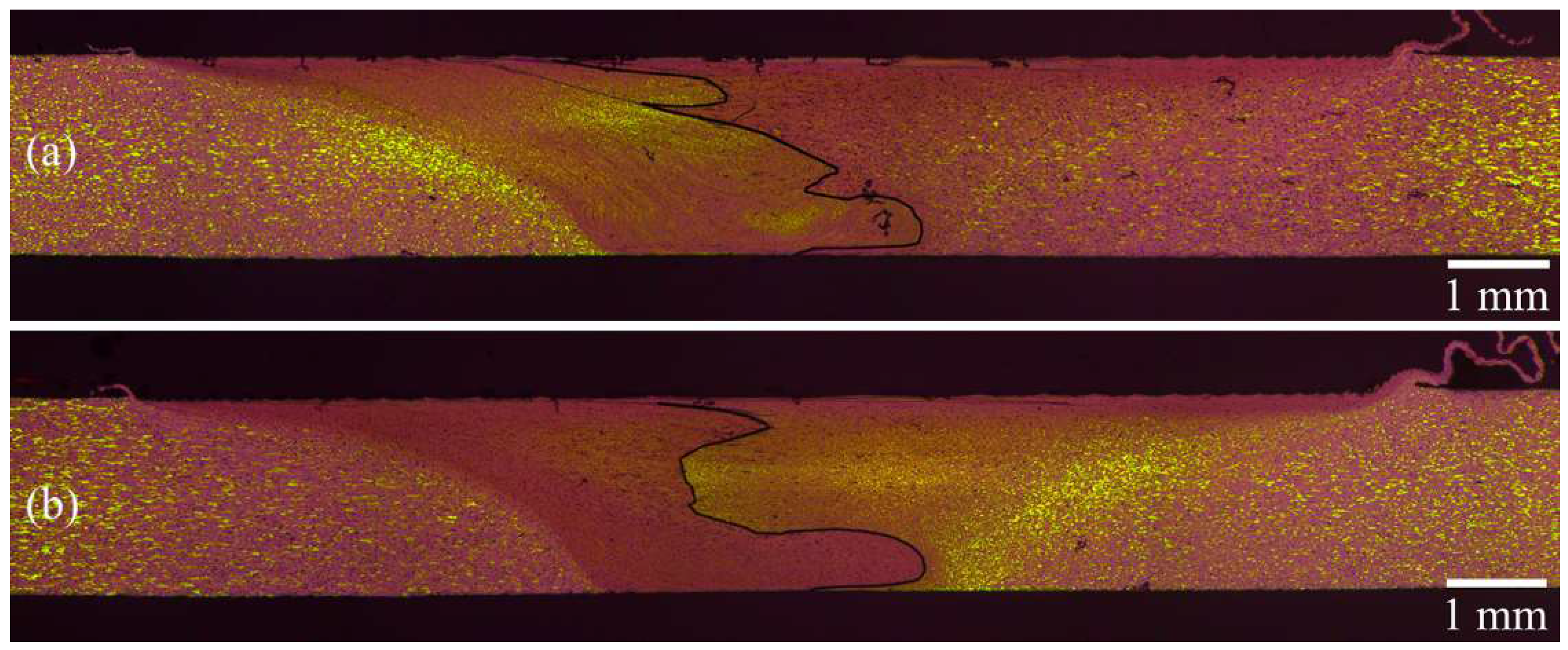
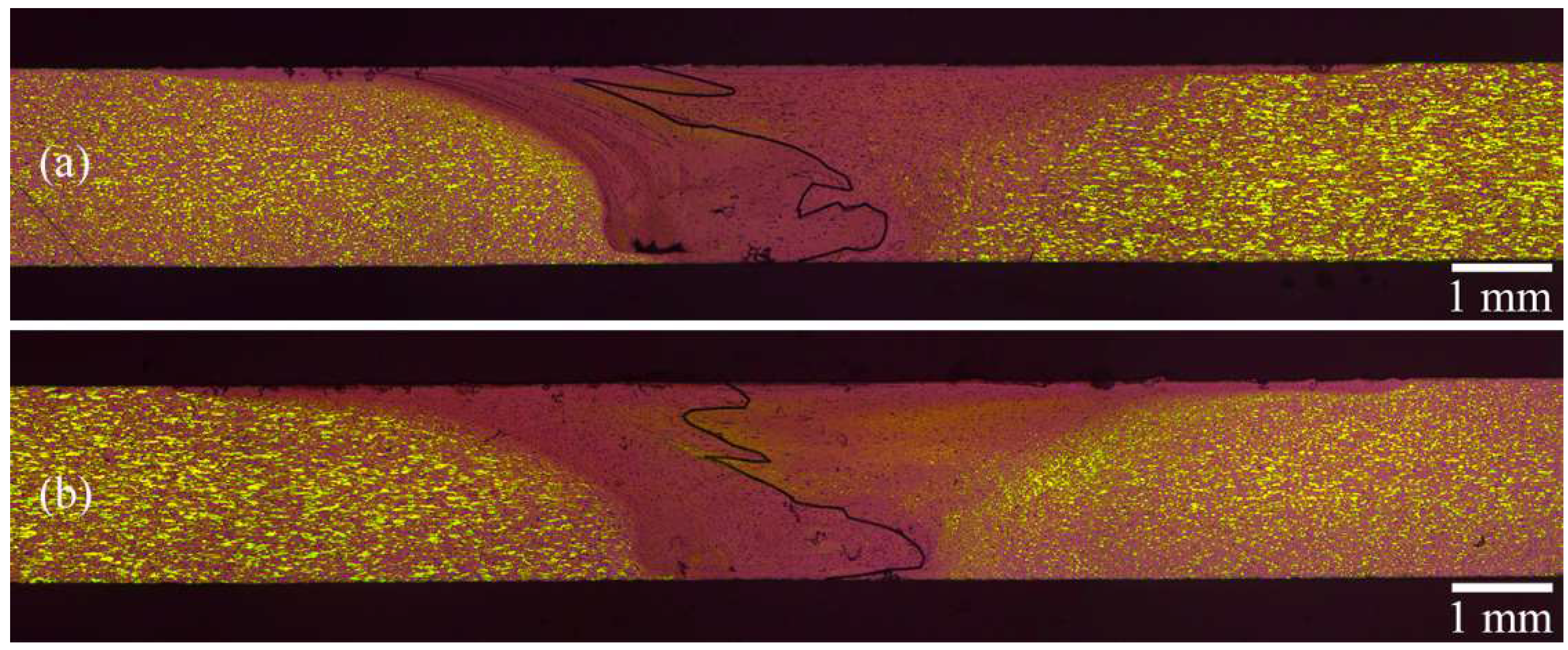
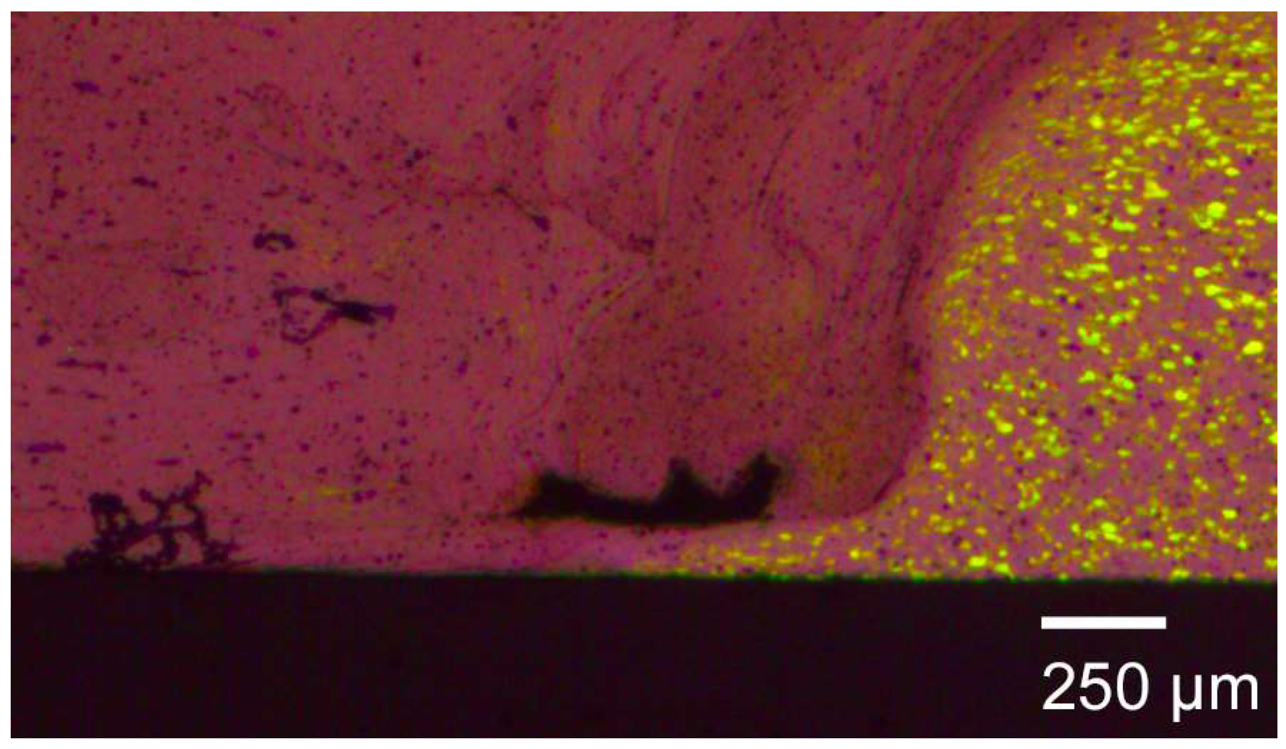
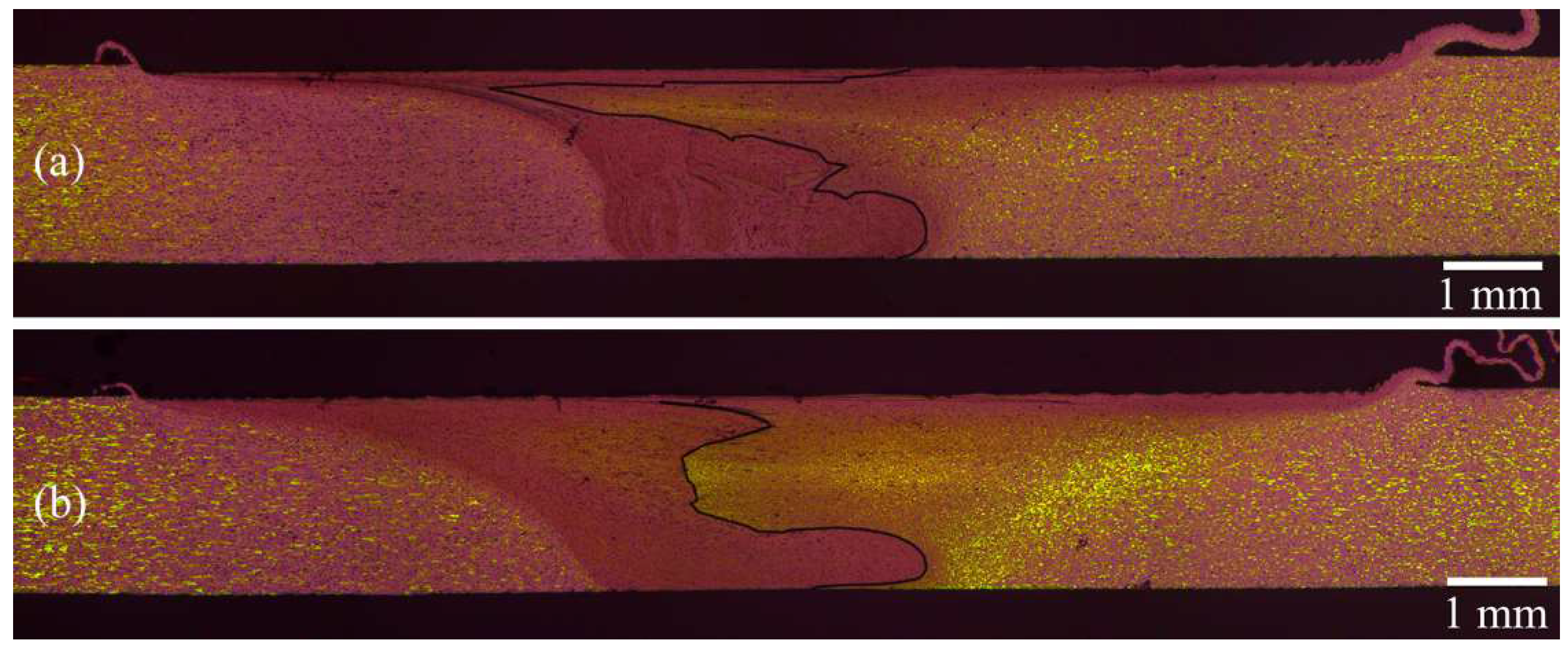
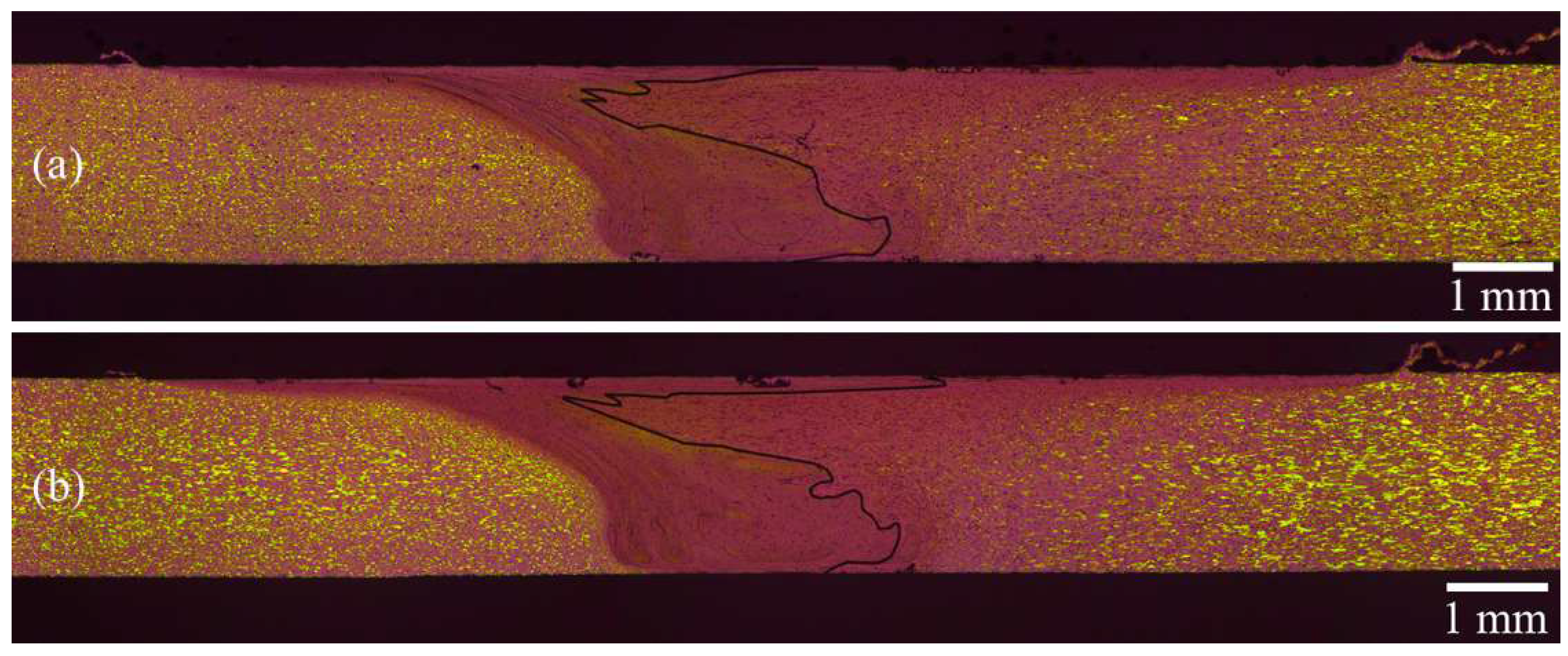
3.1.2. Microstructural Analysis

For a clearer understanding of the analysis of all the generated microstructures, the AS of the joint was always located on the left-hand side of the pictures.
In Figure 5, the microstructures of the joints obtained at 3 mm/s, with in the AS AA7050 (Figure 5a) and AA2024 (Figure 5b), are shown.
Note that, in the AS, the border between the Stir Zone (SZ) and the Thermo-Mechanically Affected Zone (TMAZ) was more defined for both configurations. This difference is due to the asymmetry of the process, which considers both material transport and heat transfer. The material in the AS was sheared around the probe and the shoulder, leading to higher heat generation by the strain energy in this location than in the RS. In the RS, the material around the probe underwent a smaller rotation and was extruded outward [22,23]. In the case of AA2024-T3 positioned in the RS (Figure 5a), it was almost impossible to distinguish between the SZ and the TMAZ at this level of magnification. This implies a more homogenous transition from the SZ to the TMAZ, but, more importantly, the dynamic recrystallisation that generates a grain size reduction in the SZ is less marked [13]. This finding could be explained by the higher strength of the AA7050-T7651 alloy, when positioned in the AS, which increases the resistance on the probe reducing the flow of the material and the effect of the shear forces on the RS in the last part of the probe rotation.
Another noticeable feature that was observed from the images was the difference in the mixture of the material in the SZ. Due to the nature of these dissimilar joints, the material flow in the centre was observed after etching through the presence of the so-called “onion rings,” the concentric rings in the SZ marked in the figure. In the case of AA2024-T3 in the AS (Figure 5b), this particular structure, appearing after joint formation, is almost symmetric with respect to the longitudinal axis. The symmetry of the material mixture could be seen as a positive aspect, which implies a better material transportation through all the thickness that led to a more homogeneous structure of the weld. On the other hand, the behaviour of AA7050 in the AS was anti-symmetric, as shown in Figure 5a, which exhibits the influence of alloy strength on material transportation.
Similar observations also apply in the case of increased welding speed for the macrographs shown in Figure 6.
For AA7050-T7651 in the AS (Figure 6a), when increasing the welding speed, the material homogeneity was improved since the higher WS caused a decrease in the heat input, which was more consistently distributed through the sample thickness. When AA2024 was placed in the AS (Figure 6b), the interface of the material started to lose the symmetric behaviour that was previously shown, with an increase in the black line tilting. In the case of AA7050 in the AS, the WS demonstrated less influence on the material mixing showing similar characteristics to what was already observed. The reduction in the SZ on the root side of the weld shows that, at higher welding speeds, the amount of material stirred by the shoulder was less influenced by the WS than the one stirred by the probe. For this reason, the interface tends to increase the tilting (Figure 6b).
With an additional increase in the welding speed, note a decrease in the Heat Affected Zone (HAZ) for both the configurations showed in Figure 7. The HAZ in AA2024 was still wider when this material was positioned in the RS.
The shape of the onion rings was very similar in both cases, showing that, by increasing the WS, the two materials interface was less influenced by the strength of the alloy positioned in the AS or RS of the joint. However, the difference in material transportation between the two materials positions could be seen from the generation of a tunnel defect at the bottom of the SZ in the AS of the joint (Figure 8).
The defect is located in the area where the weld temperature decreases and also the stirring mechanism of the probe is reduced due to the tapered geometry and the consequent reduction of the tangential velocity. This defect was found only in the case when the AA7050 was placed in the AS of the joint and consequently underwent a larger straining that could not be followed due to the reduced ductility of the base material (see Table 2).

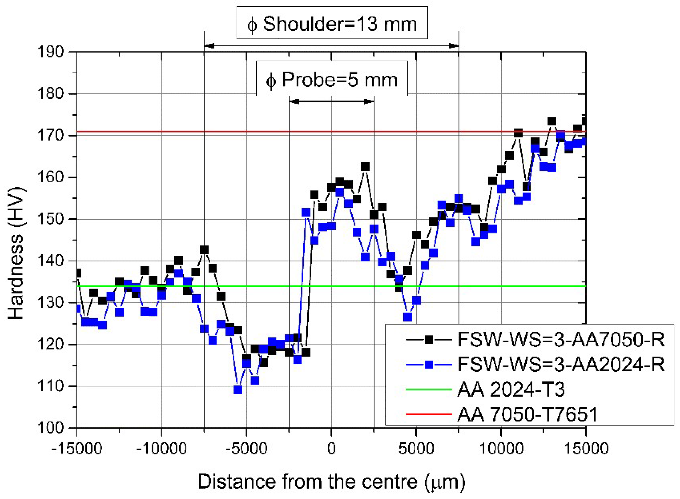
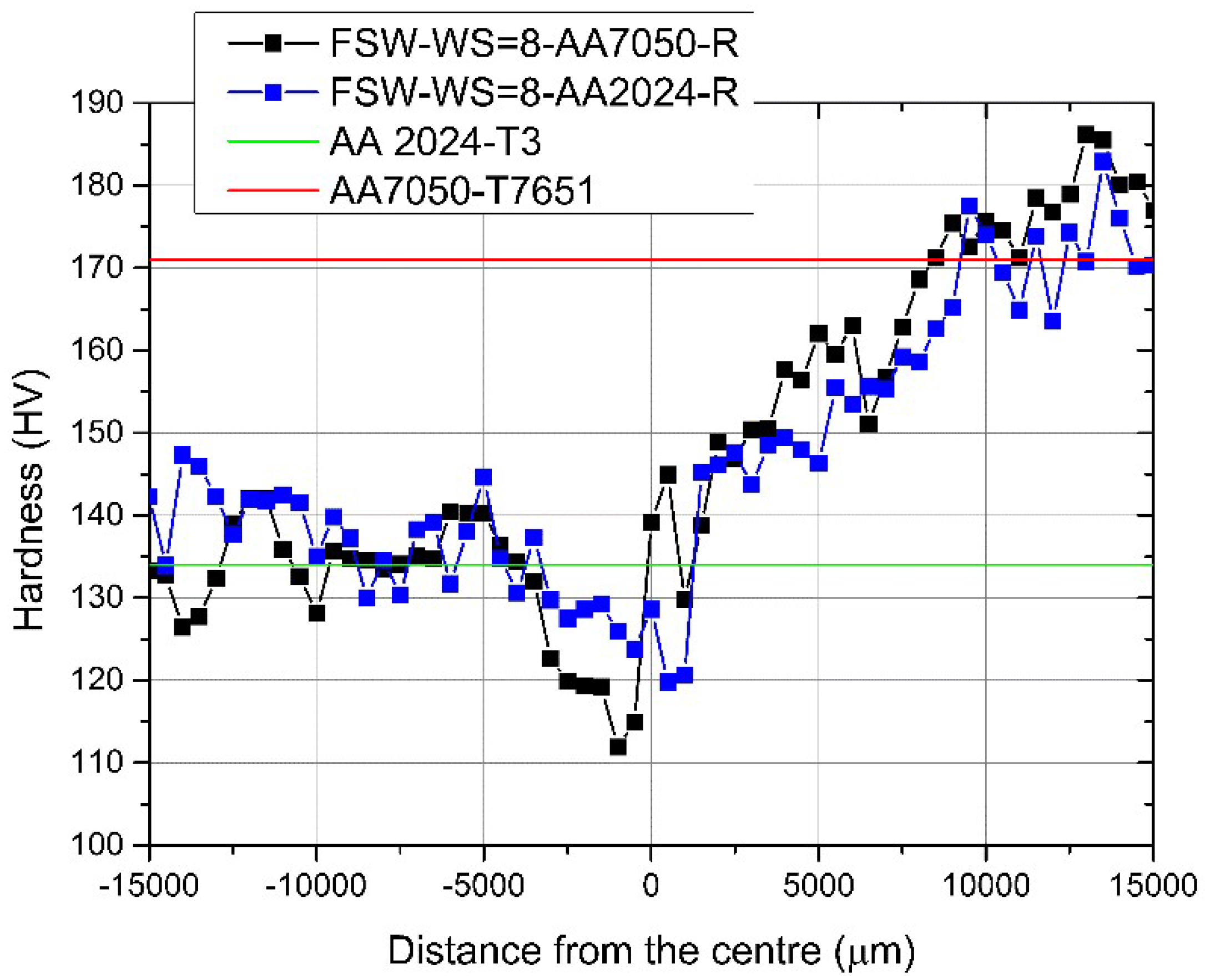
3.1.3. Microhardness Analysis

To directly compare the hardness trend in the two materials, AA2024 was always positioned on the left side of the following graphs. Consequently, the AS and RS of the joints are inverted in the two hardness profiles plotted in each figure. Figure 9 showed the hardness profile for a WS = 3 mm/s. In this figure, the diameters of the shoulder and the probe are represented to correlate the variation in the hardness profile with the tool used for the process.
In both of the cases represented, it was possible to see an increase in the hardness in the proximity of the probe where the SZ of the weld was located. This increment was due to the combined actions of the shear forces applied by the probe on the material and the dynamic recrystallisation that caused grain refinement in the SZ. However, the main factor influencing the hardness in this area, where the highest temperature is reached, is correlated with the dissolution of precipitates and the possibility for the solutes to precipitate and age again [24].
In the space between the probe and the shoulder, the hardness dropped significantly, especially in the AS. In this part, it is possible to identify two different zones in the weld, namely, the TMAZ and the HAZ. These areas are characterised by the absence of direct actions of the probe on the material, while the heat generated by the weld was still affecting them. The shear layers of the plasticised material in direct contact with the probe and the shoulder influenced the material in the TMAZ. In this area, the hardness reached the minimum in both sides of the joint and for the two different positions of the materials. The temperature reached in the TMAZ is not high enough to favor the dissolution of precipitates that would instead transform and coarsen, reducing drastically the hardness and the strength of the material. In the AA2024, the Guinier-Preston-Bagaryatsky (GPB) zones are gradually transforming into S’(S) strengthening precipitates that would increase in percentage with the temperature and subsequently coarsen. The precipitates in the AA7050 undergo a similar transformation evolving from super solute to Guinier-Preston (GP) zones and in the TMAZ become coarsened η(MgZn2) precipitates that show a minimum hardness.
On the other hand, in the HAZ, there is no mechanical action introduced in the material, and the modification of the microstructure is only due to the transmission of heat. The hardness increased gradually in the AS and RS until the original value of the respective base material was attained. Only small differences in the hardness profile between the two material positions were evident. Moreover, it was possible to observe that both the materials reached their original hardness more rapidly when they were positioned in the AS. This consideration was important especially for the AA2024 side, where failure was more probable.
When increasing the WS (Figure 10), it is possible to notice a divergence in the hardness behaviour at the side of the AA7050-T7651 alloy. When this material was positioned in the AS, the hardness increased faster due to the sharper transition between the SZ and HAZ previously seen in the microstructural observations.
In the weaker part of the weld, there was no significant dissimilarity in the TMAZ from the side of AA2024-T3. The difference in the two cases between the minimum values reached by the hardness profiles is 5 HV that, according to Tabor’s equation [25], should lead to a difference in the yield stress of approximately 18 MPa.
In Figure 11, the case when the WS increased until 8 mm/s was shown. The hardness performance was improved for both the situations, especially in the case of the AA2024-T3 in the AS. Here, the minimum of the hardness was greater than 120 HV, and the variation was limited to a small area close to the probe diameter.
An increase in the WS and consequently a decrease in the heat input leads to a lower temperature peak during the weld and causes a smoother hardness profile. All of the typical welding zones were reduced in size, especially in the proximity of the weld centre. Once again, both of the materials returned to their original hardness values more rapidly when they were in the AS, even if the difference between the two cases was minimal for the highest WS.

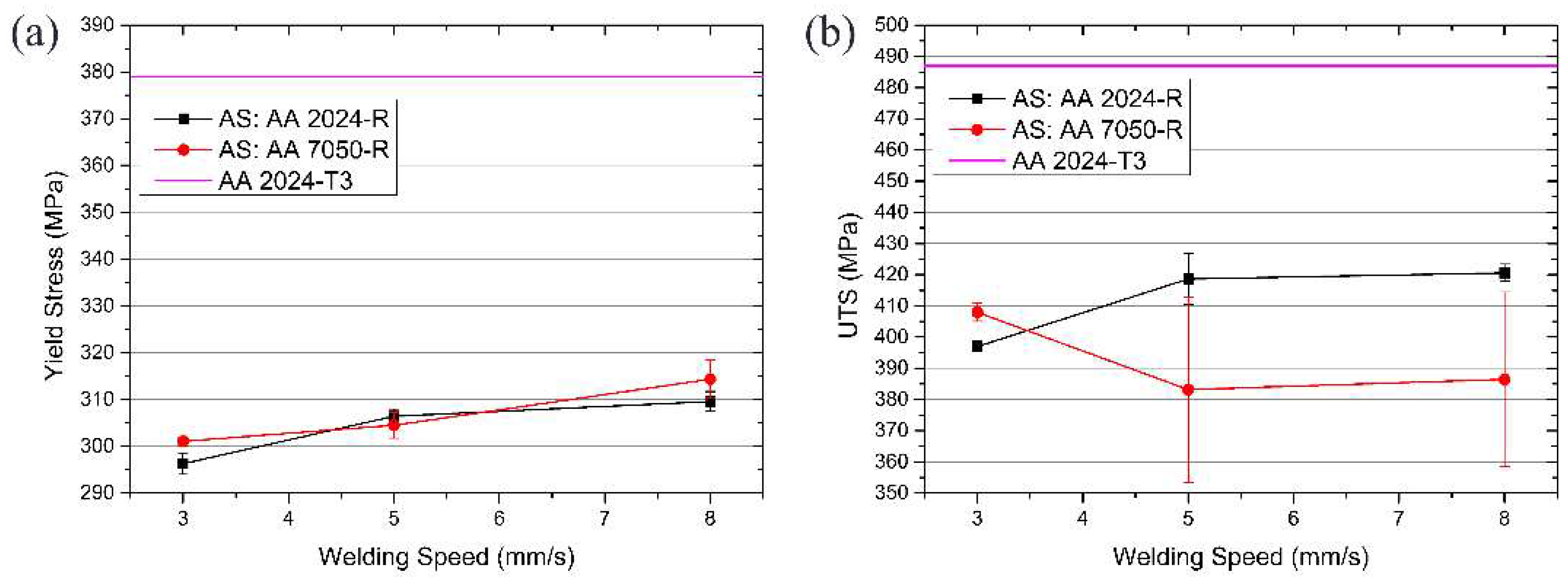
3.1.4. Mechanical Characterisation

In the bending analysis, the minimum angle that the specimen should reach to pass the test was 80°, considering that the base material testing of AA7050-T7651 broke at an angle of approximately 90°. Table 4 shows the results obtained from changing the position of the materials.
All of the specimens except one, AA7050-T7651 in the AS and in the rolling direction, did not pass the test. This result showed a preliminary influence of the material location on the mechanical properties of the joints, considering that the entire set of specimens with the material in the rolling direction and AA2024-T3 have to overcome this step of 80°.
Figure 12a illustrates the variation in the yield stress as a function of increasing WS for AA 2024-T3 in both the advancing side and the retreating side.
For both of the cases, the yield stress increased with increasing welding speed. This finding agrees with the microhardness test results and the macrograph investigation. The reduction in the heat input caused a shrinking in the TMAZ and HAZ sizes with smaller grain growth. The peak of the temperature during the process was reduced, which influenced the precipitate transformation and coarsening. Furthermore, when the WS increased, the forging force of the probe increased, which applied larger shear forces to the material that generated a more refined grain structure with better mechanical properties.
The values of the yield stress, considering also the scatter, did not show significant variations in the changing position of the material. The maximum difference obtained from the test is 5 MPa. The difference between the positions of the two materials was represented by an enlargement in the scattering of the results when AA7050-T7651 was positioned in the AS and the welding speed was increased. The reason for this behaviour could be caused by a major sensitivity to external factors, such as the non-perfect clamping of the plates, or internal factors such as a variation in the precipitate distribution and residual stresses in the material that caused a less stable process.
This last observation was confirmed by the joint strength analysis presented in Figure 12b. When increasing the WS, the UTS dropped drastically, and the scatter in the results increased to high levels for AA7050 in the AS of the weld. This finding confirmed the instability of the process along the welds. The analysis of the fracture location for the different welding conditions showed that, for the low welding speed and for all the specimens with AA2024 in the AS, the fracture happened in the TMAZ where the minimum hardness was measured (Table 5). This is clearly explained by the degradation mechanism of the precipitates due to the high temperatures. At higher welding speeds with the AA7050 in the AS, i.e., when the tensile strength dropped, the failure location moved toward the centre of the SZ. In this case, the reason for the premature failure was dependent on the unstable plasticisation when the temperature decreased that, combined with the higher strength and lower ductility of AA7050, did not allow the complete mixing and interlocking of the materials in the centre of the joint.
When AA2024 was in the AS, a WS of 8 mm/s and a UTS value of 86.4% of the base material was obtained. The scatter, at all WSs, remained under 3% of the absolute value measured, confirming the stable behaviour of the weld along all the line.
The materials position clearly influenced the strain mechanism around the tool and the heat generation. When the AA7050 was located in the AS of the weld, the transportation of the material is reduced as certified by the decreased torque and heat input due to the higher strength and lower ductility of the alloy. While an improvement in the precipitates evolution could be attested for in this configuration for the two lower welding speeds, as seen from the hardness profile measured, this did not bring any benefit in the joint performance under tensile and bending tests. The ductility of the joint was reduced and, at higher welding speeds, the fracture location moved to the interface between the two alloys in the SZ centre. The problem of positioning the AA7050 in the AS is that it resulted as impossible to improve joint performances due to the reduced strength at low welding speeds caused by the coarsening of precipitates in the TMAZ, where the AA2024 is located, and the lack of material transportation at higher welding speeds that led to a reduction of the bonding mechanism between the two alloys and the formation of defects. On the other hand, when the AA2024 was placed in the AS, the joint properties could be improved by increasing the welding speed, hence reducing the heat input in the weld and the area affected by it, without excessively reducing the material transportation around the tool that would cause a transition of the fracture to the SZ.

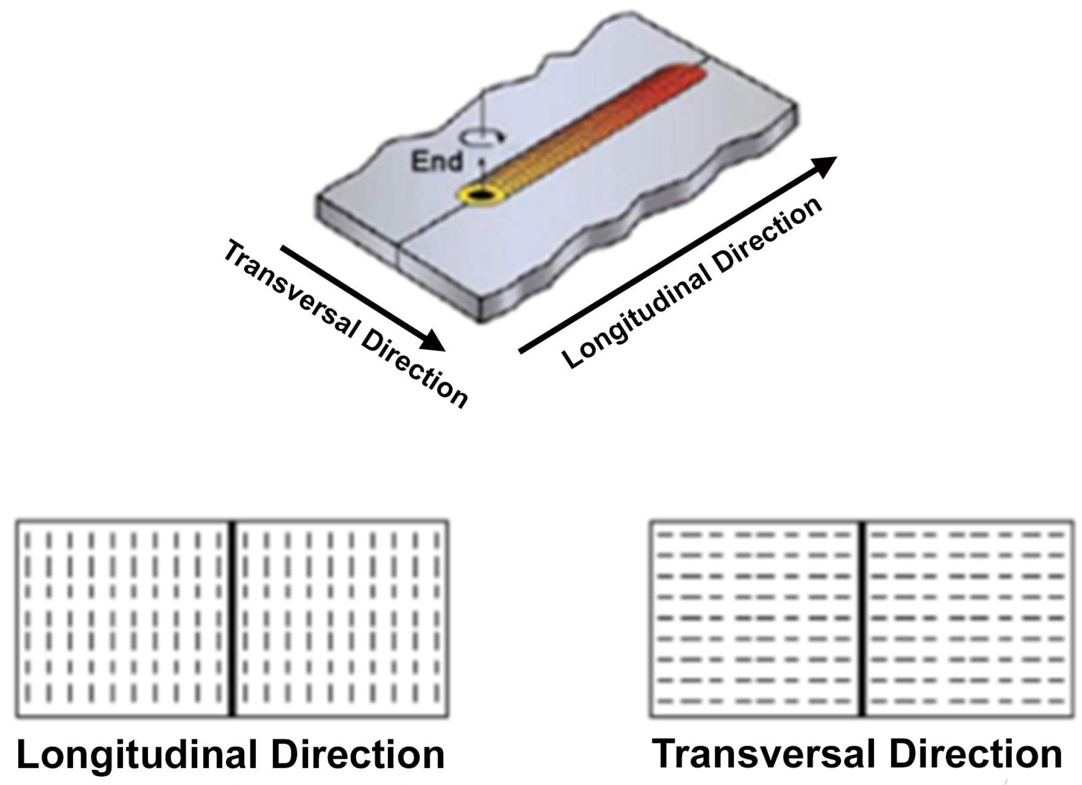
3.2. Direction of the Materials

The influence of the rolling orientation in respect to the welding direction on the joints properties was performed in a similar way to what was previously done for the materials’ positioning. The investigation starts with the analysis of the influence on the heat generation to subsequently see how this affects the microstructure and mechanical characteristics of the joints.

3.2.1. Process Analysis

For the analysis on the process, the measured values for AA2024 in the rolling direction and in the AS were used as a reference. The material position and orientation were changed to show both the alloys in the AS and perpendicular to rolling orientation (Figure 13).
In a comparison of the curves for AA2024-T3 in the AS, all of the parameters analysed were similar and in the limit of the tolerance when the welding speed reached 5 mm/s. The influence of the material orientation was evident at the lower WSs where the contact between the tool and the surrounding material in each rotation increased. The anisotropy of the base material in the two main directions led to an increase in the force (Figure 13a) due to the lower deformability in the transverse direction of the material in front of the tool and a decrease in the torque (Figure 13b) due to the lower strength. The results are also similar when comparing AA7050-T7651 in the AS for the two orientations.

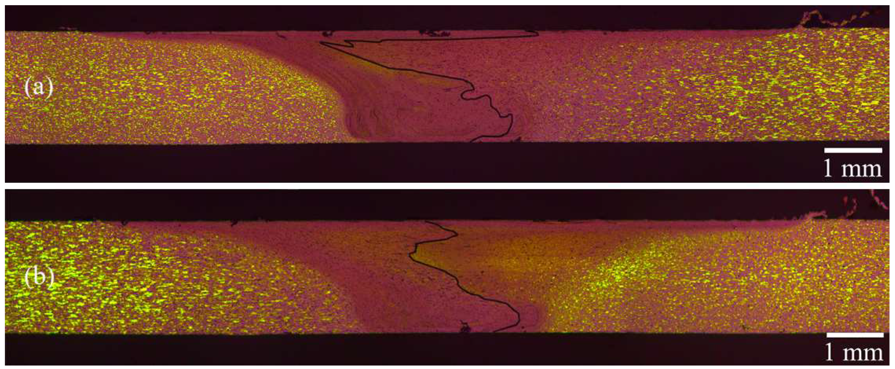
3.2.2. Microstructural Analysis

Figure 14 represents the case of AA2024 in the AS of the weld for the two directions of the materials and a low WS.
In the case of a material orientation perpendicular to the rolling direction, the zone affected by the shoulder was more limited, and the shape of the SZ was parallel to the probe at the root side of the weld. With the material disposed in the rolling direction, the slope of the borders between the SZ and TMAZ is less steep. The two HAZs on both the sides of the SZ have comparable dimensions with no noticeable difference in the shape. The mixing of the materials was influenced by their orientation, and a more asymmetric interface was exhibited for the sample shown in Figure 14a.
In AA7050 in the AS, there were no remarkable differences between the two macrographs (Figure 15). The sizes of the all the characteristic welding zones were not influenced significantly by the orientation of the materials.
The “onion rings” did not change shape or orientation, indicating that the rolling or perpendicular to the rolling directions are not influenced by material transportation. In general, it appears that, when a high-strength material is in the AS of the joint, both the welding parameters and the material orientation demonstrate a lower influence on this interface.

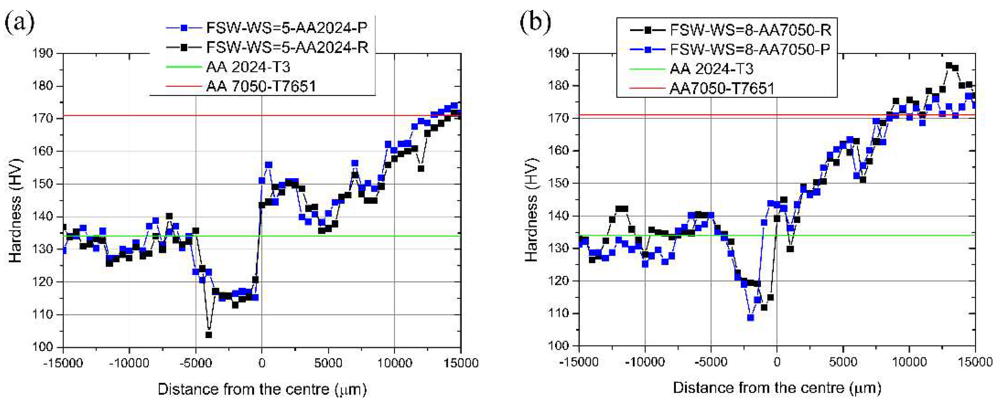
3.2.3. Microhardness Analysis

In Figure 16a, the influence of the direction of the materials can be seen in the case of the average WS and for the AA2024-T3 alloy positioned in the AS of the weld.
No remarkable differences can be seen in the hardness profile with a change in the direction of the materials. The lowest point in the case of the plates in the rolling direction is probably due to the presence of a lower hardness precipitate in the indentation area. The same conclusion could be drawn for the highest WS and with AA7050-T7651 in the AS (Figure 16b). The only difference is a slight movement of the curve in the proximity of the SZ to the AA7050 side for the plates disposed in the rolling direction.
From this study, is it possible to conclude that the direction of the materials does not influence the hardness profile for different WSs and material dispositions, i.e., its values or shape. The low difference previously shown in the calculated heat input does not justify variations in the precipitation mechanism for different material orientations; hence, no variation in the hardness profile could be expected.

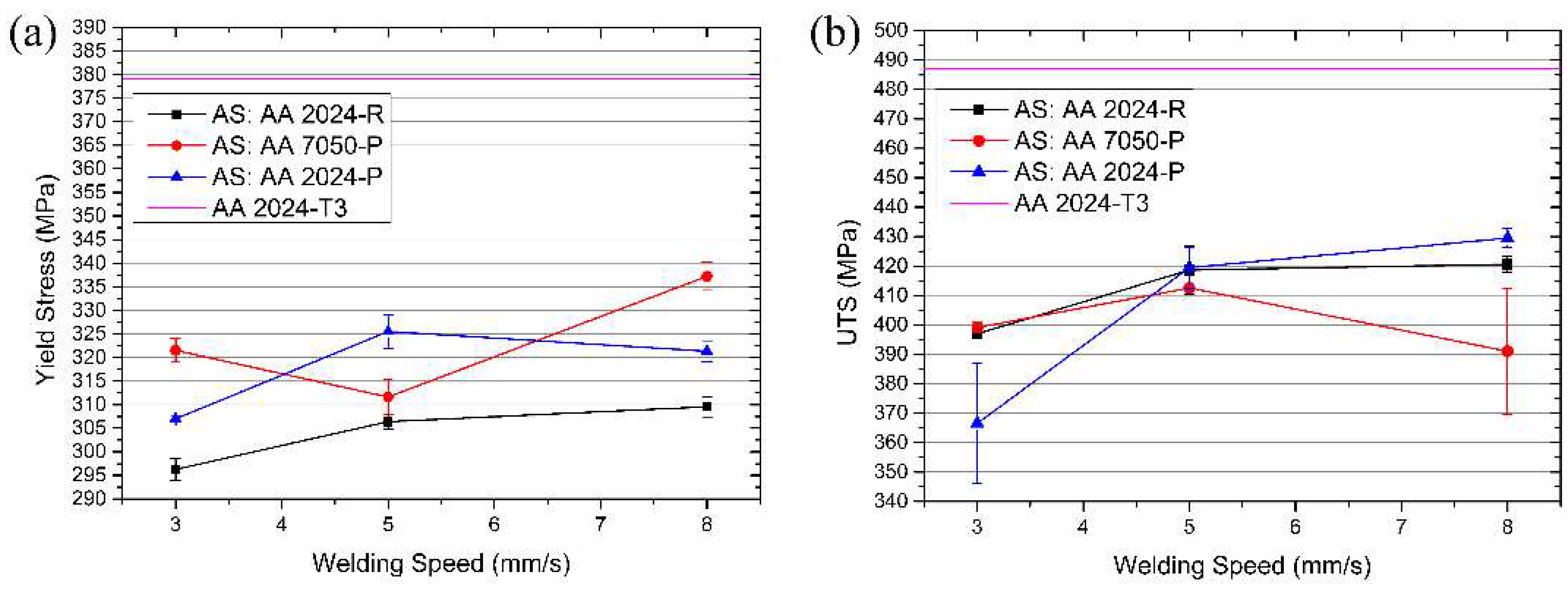
3.2.4. Mechanical Characterisation

The bending test results are listed in Table 6. The results of the test obtained for the AA2024-T3 alloy in the AS and in rolling direction were used as a comparison.
None of the specimens in the direction perpendicular to the rolling direction passed the test when welded with the highest WS.
The analysis of the yield stress was performed in a similar manner to that performed during the process analysis with AA2024-T3 in the AS and in the rolling direction used as reference for the other two cases (Figure 17a). The same procedure was followed in the study of the joint strength.
The yield stress obtained in plates disposed perpendicularly to the rolling direction is higher for all the WSs than that in the rolling direction. In the case of the plates in the rolling direction, the yield stress improved with increasing WS, while, in the other two cases, there is a variability that does not allow any assumption regarding possible trends in the process. The difference in the yield stress with the changing direction of the materials is significant, especially when comparing the values at higher welding speeds. The explanation is related to the different strengths of the base materials in the two main directions and the lower influence of the modified microstructures at lower load levels.
For the ultimate tensile test (Figure 17b), the behaviour of the weld with AA7050 in the AS was not influenced by the orientation of the materials. The mechanical properties of the joint decrease when the WS increases and their stability is poor. The fracture behaviour was also similar to the parent configuration with the materials in the rolling direction in Table 7. The final failure was mostly located in the centre of the SZ at the interphase between the two alloys.
In the case of AA2024-T3 in the AS, similar results were obtained at middle and high WSs for both material directions. The best result for the high WS reached 88.2% of the base material with an increment of the 2% with respect to the configuration in the rolling direction. At low WS, the tensile strength, when the orientation of the materials was perpendicular to the rolling direction, was considerably lower with a high scatter of the values. Once again, in this case, the fracture location moved to the centre of the SZ at the interphase. As previously shown (Figure 14), the alloys interphase in the case of orientation perpendicular to the rolling direction resulted in being asymmetric and similar to the one obtained for AA7050 in the AS. This specific configuration is probably leading to a reduction in joining force in the centre of the weld due to poor material transportation.

4. Conclusions

The influence of the direction and position of the materials on the microstructure and mechanical performance of the welds was systematically analysed. An analysis of the process showed a reduction in the heat generated with the AA7050-T7651 material positioned in the AS of the weld caused by a general decrease in the torque. The material orientation influences the heat generated with a smaller reduction when the two alloys are oriented perpendicular to the rolling direction. This small variation is due to the anisotropy of the rolled base materials.
There is a relevant advantage in positioning the AA2024-T3 alloy in the AS of the weld, which was verified by all the tests performed, especially considering the results obtained from the bending test and the tensile test. In this last test, even with a decrease in the yield stress, the improvement in the ultimate tensile stress is remarkable and shows the best support for this conclusion. This increase was justified by the better material transportation that led to a failure in the TMAZ where the minimum hardness was measured. Another important point is the higher stability of the tensile tests outcome for AA2024-T3 in the AS of the weld, confirmed by the lower standard deviation of the results for all the WSs considered.
The material orientation is a more complicated matter, and the results do not show a clear direction to take when choosing between the rolling or perpendicular direction in order to improve the joint strength. On one hand, the best results in the bending test were obtained by positioning the plates in the rolling direction since all the specimens passed the test. Meanwhile, the tensile test showed better behaviour regarding the yield stress in the case of the material disposition perpendicular to the rolling direction, while only a small difference between the two configurations was present considering the ultimate tensile stress. At a lower WS, the weld realised with the plates in the rolling direction exhibited a higher ultimate stress and a reduced scatter of the measured values. At a microstructural point of view, the differences were minimal at the magnitude of the macrograph used. The hardness profiles for the two cases analysed were almost identical, which suggests a slight influence of the direction of the material in the evolution of the precipitates.

Acknowledgments

This work embedded in the Research Platform ACE has been carried out within the scope of the Research Platform “Light-weight Assessment, Computing and Engineering Centre” (ACE Centre) as part of the reference project Lightweight Integral Structures for Future Generation Aircrafts (LISA).

Author Contributions

A.B. and J.F.d.S. conceived the design of experiments; A.B. performed the experiments analysed the data and wrote the article; J.C. performed the welds and contributed to the process analysis.

Conflicts of Interest

The authors declare no conflict of interest.

References

  1. Li, G.; Shi, G.; Bellinger, N.C. 6—Assessing the riveting process and the quality of riveted joints in aerospace and other applications A2—Chaturvedi, M.C. In Welding and Joining of Aerospace Materials; Woodhead Publishing: Sawston, UK, 2012; pp. 181–214. [Google Scholar]
  2. Kwakernaak, A.; Hofstede, J.; Poulis, J.; Benedictus, R. 8—Improvements in bonding metals for aerospace and other applications A2—Chaturvedi, M.C. In Welding and Joining of Aerospace Materials; Woodhead Publishing: Sawston, UK, 2012; pp. 235–287. [Google Scholar]
  3. Thomas, W.M.; Nicholas, E.D.; Needham, J.C.; Murch, M.G.; Temple-Smith, P.; Dawes, C.J. Improvements to Friction Welding. Patent EP 065,326,5A2, 6 December 1991. [Google Scholar]
  4. Mishra, R.S.; Ma, Z.Y. Friction stir welding and processing. Mater. Sci. Eng. 2005, 50, 1–78. [Google Scholar] [CrossRef]
  5. Nandan, R.; DebRoy, T.; Bhadeshia, H.K.D.H. Recent advances in friction-stir welding—Process, weldment structure and properties. Prog. Mater. Sci. 2008, 53, 980–1023. [Google Scholar] [CrossRef]
  6. Guo, J.F.; Chen, H.C.; Sun, C.N.; Bi, G.; Sun, Z.; Wei, J. Friction stir welding of dissimilar materials between AA6061 and AA7075 al alloys effects of process parameters. Mater. Des. 2014, 56, 185–192. [Google Scholar] [CrossRef]
  7. Amancio-Filho, S.T.; Sheikhi, S.; dos Santos, J.F.; Bolfarini, C. Preliminary study on the microstructure and mechanical properties of dissimilar friction stir welds in aircraft aluminium alloys 2024-T351 and 6056-T4. J. Mater. Process. Technol. 2008, 206, 132–142. [Google Scholar] [CrossRef]
  8. Khodir, S.A.; Shibayanagi, T. Friction stir welding of dissimilar AA2024 and AA7075 aluminum alloys. Mater. Sci. Eng. B 2008, 148, 82–87. [Google Scholar] [CrossRef]
  9. Da Silva, A.A.M.; Arruti, E.; Janeiro, G.; Aldanondo, E.; Alvarez, P.; Echeverria, A. Material flow and mechanical behaviour of dissimilar AA2024-T3 and AA7075-T6 aluminium alloys friction stir welds. Mater. Des. 2011, 32, 2021–2027. [Google Scholar] [CrossRef]
  10. Barbini, A.; Carstensen, J.; dos Santos, J.F. Influence of a non-rotating shoulder on heat generation, microstructure and mechanical properties of dissimilar AA2024/AA7050 FSW joints. J. Mater. Sci. Technol. 2018, 34, 119–127. [Google Scholar] [CrossRef]
  11. Fuller, C.B.; Mahoney, M.W.; Calabrese, M.; Micona, L. Evolution of microstructure and mechanical properties in naturally aged 7050 and 7075 Al friction stir welds. Mater. Sci. Eng. A 2010, 527, 2233–2240. [Google Scholar] [CrossRef]
  12. Zhou, L.; Wang, T.; Zhou, W.L.; Li, Z.Y.; Huang, Y.X.; Feng, J.C. Microstructural characteristics and mechanical properties of 7050-T7451 aluminum alloy friction stir-welded joints. J. Mater. Eng. Perform. 2016, 25, 2542–2550. [Google Scholar] [CrossRef]
  13. Su, J.Q.; Nelson, T.W.; Mishra, R.; Mahoney, M. Microstructural investigation of friction stir welded 7050-T651 aluminium. Acta Mater. 2003, 51, 713–729. [Google Scholar] [CrossRef]
  14. Genevois, C.; Fabrègue, D.; Deschamps, A.; Poole, W.J. On the coupling between precipitation and plastic deformation in relation with friction stir welding of AA2024 T3 aluminium alloy. Mater. Sci. Eng. A 2006, 441, 39–48. [Google Scholar] [CrossRef]
  15. Sutton, M.A.; Yang, B.; Reynolds, A.P.; Taylor, R. Microstructural studies of friction stir welds in 2024-T3 aluminum. Mater. Sci. Eng. A 2002, 323, 160–166. [Google Scholar] [CrossRef]
  16. Bousquet, E.; Poulon-Quintin, A.; Puiggali, M.; Devos, O.; Touzet, M. Relationship between microstructure, microhardness and corrosion sensitivity of an AA 2024-T3 friction stir welded joint. Corros. Sci. 2011, 53, 3026–3034. [Google Scholar] [CrossRef]
  17. Carlone, P.; Palazzo, G.S. Influence of process parameters on microstructure and mechanical properties in AA2024-T3 friction stir welding. Metallogr. Microstruct. Anal. 2013, 2, 213–222. [Google Scholar] [CrossRef]
  18. Khandkar, M.Z.H.; Khan, J.A.; Reynolds, A.P. Prediction of temperature distribution and thermal history during friction stir welding: Input torque based model. Sci. Technol. Weld. Join. 2003, 8, 165–174. [Google Scholar] [CrossRef]
  19. Dursun, T.; Soutis, C. Recent developments in advanced aircraft aluminium alloys. Mater. Des. 2014, 56, 862–871. [Google Scholar] [CrossRef]
  20. Tongne, A.; Desrayaud, C.; Jahazi, M.; Feulvarch, E. On material flow in friction stir welded Al alloys. J. Mater. Process. Technol. 2017, 239, 284–296. [Google Scholar] [CrossRef]
  21. Cui, S.; Chen, Z.W.; Robson, J.D. A model relating tool torque and its associated power and specific energy to rotation and forward speeds during friction stir welding/processing. Int. J. Mach. Tools Manuf. 2010, 50, 1023–1030. [Google Scholar] [CrossRef]
  22. Chen, Z.W.; Pasang, T.; Qi, Y. Shear flow and formation of nugget zone during friction stir welding of aluminium alloy 5083-O. Mater. Sci. Eng. A 2008, 474, 312–316. [Google Scholar] [CrossRef]
  23. Arbegast, W.J. A flow-partitioned deformation zone model for defect formation during friction stir welding. Scr. Mater. 2008, 58, 372–376. [Google Scholar] [CrossRef]
  24. Zhang, Z.; Xiao, B.L.; Ma, Z.Y. Hardness recovery mechanism in the heat-affected zone during long-term natural aging and its influence on the mechanical properties and fracture behavior of friction stir welded 2024Al–T351 joints. Acta Mater. 2014, 73, 227–239. [Google Scholar] [CrossRef]
  25. Tabor, D. The physical meaning of indentation and scratch hardness. Br. J. Appl. Phys. 1956, 7, 159. [Google Scholar] [CrossRef]
Figure 1. Relation between the rolling and the welding directions.
Metals 08 00202 g001
Figure 2. 3D model of the FSW tool.
Metals 08 00202 g002
Figure 3. Microhardness measurement indentations across a FSW joint.
Metals 08 00202 g003
Figure 4. Measured forces and calculated energy input for different material positions.
Metals 08 00202 g004
Figure 5. Cross sections of (a) FSW-WS = 3-AA7050-R and (b) FSW-WS = 3-AA2024-R.
Metals 08 00202 g005
Figure 6. Cross sections of (a) FSW-WS = 5-AA7050-R and (b) FSW-WS = 5-AA2024-R.
Metals 08 00202 g006
Figure 7. Cross sections of (a) FSW-WS = 8-AA7050-R and (b) FSW-WS = 8-AA2024-R.
Metals 08 00202 g007
Figure 8. Defect detail generated in the specimen FSW-WS = 8-AA7050-R.
Metals 08 00202 g008
Figure 9. Microhardness test results for WS = 3 mm/s and the different positioning of the materials.
Metals 08 00202 g009
Figure 10. Microhardness test results for WS = 5 mm/s and the different positioning of the materials.
Metals 08 00202 g010
Figure 11. Microhardness test results for WS = 8 mm/s and the different positioning of the materials.
Metals 08 00202 g011
Figure 12. Variation in the (a) Yield Stress (YS) and (b) UTS with changing WS and the material position.
Metals 08 00202 g012
Figure 13. Measured: (a) Welding force, (b) Torque and (c) calculated energy input for the different material orientations.
Metals 08 00202 g013
Figure 14. Cross sections of (a) FSW-WS = 3-AA2024-P and (b) FSW-WS = 3-AA2024-R.
Metals 08 00202 g014
Figure 15. Cross section of (a) FSW-WS = 5-AA7050-P and (b) FSW-WS = 5-AA7050-R.
Metals 08 00202 g015
Figure 16. Microhardness for different material orientations: (a) WS = 5 mm/s, AA2024AS and (b) WS = 8 mm/s, AA7050AS.
Metals 08 00202 g016
Figure 17. Variation in the (a) YS and (b) UTS with changing WS, the material position and direction.
Metals 08 00202 g017
Table 1. Mechanical properties of the aluminium alloy AA2024-T3.
Mechanical Properties of AA 2024-T3
Hardness, VickersYield Strength (MPa)Tensile Strength (UTS) (MPa)Elongation at Break (%)
134LTDLTD20.15
379319325487474468
Table 2. Mechanical properties of the aluminium alloy AA7050-T7651.
Mechanical properties of AA 7050-T7651
Hardness, VickersYield Strength (MPa)UTS (MPa)Elongation at Break (%)
17149055211
Table 3. Specimens’ ID and welding parameters.
Specimen IDWelding Speed (mm/s)Material in the Advancing Side (AS)Direction of the Materials with Respect to the Welding Direction
FSW-WS = 3-AA2024-R3AA2024-T3Rolling
FSW-WS = 3-AA7050-R3AA7050-T7651Rolling
FSW-WS = 3-AA2024-P3AA2024-T3Perpendicular
FSW-WS = 3-AA7050-P3AA7050-T7651Perpendicular
FSW-WS = 5-AA2024-R5AA2024-T3Rolling
FSW-WS = 5-AA7050-R5AA7050-T7651Rolling
FSW-WS = 5-AA2024-P5AA2024-T3Perpendicular
FSW-WS = 5-AA7050-P5AA7050-T7651Perpendicular
FSW-WS = 8-AA2024-R8AA2024-T3Rolling
FSW-WS = 8-AA7050-R8AA7050-T7651Rolling
FSW-WS = 8-AA2024-P8AA2024-T3Perpendicular
FSW-WS = 8-AA7050-P8AA7050-T7651Perpendicular
Table 4. Results of the bending test for the material position.
Specimen IDBending Test Results
Begin of the WeldEnd of the Weld
FSW-WS = 3-AA2024-RVV
FSW-WS = 3-AA7050-RVX
FSW-WS = 5-AA2024-RVV
FSW-WS = 5-AA7050-RXX
FSW-WS = 8-AA2024-RVV
FSW-WS = 8-AA7050-RXX
Table 5. Fracture location with changing WS and the material position.
Specimen IDFracture Location
FSW-WS = 3-AA2024-RAS-TMAZ
FSW-WS = 3-AA7050-RRS-TMAZ
FSW-WS = 5-AA2024-RAS-TMAZ
FSW-WS = 5-AA7050-RSZ
FSW-WS = 8-AA2024-RAS-TMAZ
FSW-WS = 8-AA7050-RSZ
Table 6. Results of the bending test for the material direction and AA2024-T3 in the AS.
Specimen IDBending Test Results
Begin of the Weld End of the Weld
FSW-WS = 3-AA2024-RVV
FSW-WS = 3-AA2024-PVX
FSW-WS = 5-AA2024-RVV
FSW-WS = 5-AA2024-PVX
FSW-WS = 8-AA2024-RVV
FSW-WS = 8-AA2024-PXX
Table 7. Fracture location with changing WS, the material position and direction.
Specimen IDFracture Location
FSW-WS = 3-AA2024-RAS-TMAZ
FSW-WS = 3-AA2024-PSZ
FSW-WS = 3-AA7050-PSZ
FSW-WS = 5-AA2024-RAS-TMAZ
FSW-WS = 5-AA2024-PAS-TMAZ
FSW-WS = 5-AA7050-PRS-TMAZ
FSW-WS = 8-AA2024-RAS-TMAZ
FSW-WS = 8-AA2024-PAS-TMAZ
FSW-WS = 8-AA7050-PSZ

