Effect of Immersion Depth of a Swirling Flow Tundish SEN on Multiphase Flow and Heat Transfer in Mold


1
Key Laboratory of Ecological Metallurgy of Multi-Metal Intergrown Ores of Education Ministry, School of Metallurgy, Northeastern University, Shenyang 110819, China
2
Department of Materials and Manufacturing Science, Graduate School of Engineering, Osaka University, 2-1, Yamadaoka, Suita, Osaka 565-0871, Japan
3
Department of Materials Science and Engineering, KTH Royal Institute of Technology, SE-100 44 Stockholm, Sweden
*
Author to whom correspondence should be addressed.
Metals 2018, 8(11), 910; https://doi.org/10.3390/met8110910
Submission received: 15 October 2018
/
Revised: 31 October 2018
/
Accepted: 5 November 2018
/
Published: 6 November 2018
(This article belongs to the Special Issue Refining and Casting of Steel)
Abstract
:The effect of the immersion depth of a new swirling flow tundish SEN (Submerged Entry Nozzle) on the multiphase flow and heat transfer in a mold was studied using numerical simulation. The RSM (Reynolds Stress Model) and the VOF (Volume of Fluid) model were used to solve the steel and slag flow phenomena. The results show that the SEN immersion depth can significantly influence the steel flow near the meniscus. Specifically, an increase of the SEN immersion depth decreases the interfacial velocity, and this reduces the risk for the slag entrainment. The calculated Weber Number decreases from 0.8 to 0.2 when the SEN immersion depth increases from 15 cm to 25 cm. With a large SEN immersion depth, the steel flow velocity near the solidification front, which is below the mold level of SEN outlet, was increased. The temperature distribution has a similar distribution characteristic for different SEN immersion depths. The high temperature region is located near the solidification front. Temperature near the meniscus was slightly decreased when the SEN immersion depth was increased, due to an increased steel moving distance from the SEN outlet to the meniscus.
1. Introduction
Multiphase flow and heat transfer are very important phenomena in the continuous casting mold. These phenomena include steel-slag flow, inclusion motion, solidification, and so on. They can significantly influence the quality of the semifinal steel product. The basis for a good control on multiphase flow and heat transfer is a desirable steel flow in mold.
In the past, many studies have been carried out to optimize the multiphase flow and heat transfer in mold. The optimization investigations firstly focused on the structure of the SEN (Submerged Entry Nozzle), such as the SEN type (straight or bifurcated) [1,2], SEN port design (shape, angle, thickness) [3,4,5,6,7,8,9,10], and SEN immersion depth [3,4,6,11]. Argon injection in SEN [11] was also a widely investigated method to improve the continuous casting process, with the aim to reduce the nozzle clogging, reduce the steel reoxidation and increase the inclusion floatation in mold. In addition to these, EMBr (Electromagnetic Braking) [12,13] and M-EMS (Mold Electromagnetic Stirring) [8,9,10] have been vastly investigated to optimize the steel flow in molds. All the above investigations aim to reduce the steel flow velocity and the flow fluctuation near the meniscus, increase superheat removal, optimize the temperature distribution, and so on. Recently, swirling flow SEN has been considered to be a promising method to further modify the steel flow in mold. The significant improvement with this method is that it can directly change the steel flow characteristics before the steel flows into the mold—for example, the prevention of an impingement jet flow from a straight SEN. It was found that the heat and mass transfer near the meniscus can be remarkably activated [14,15,16,17], and a uniform velocity distribution can be obtained within a short distance from the SEN outlet [14,15,16]. Furthermore, the penetration depth of the SEN outlet flow is remarkably decreased in a billet mold [14,17]. Industrial trial results [18] show that the swirling flow SEN effectively improved the steel product quality and reduced the clogging problem of the SEN side ports.
In order to produce a swirling flow inside the SEN, the swirl blade method [14,15,16,17,18] and electromagnetic stirring method [19,20,21,22] were investigated in many studies. The lifespan of the swirl blade and the inclusion deposition on its surface, which may lead to nozzle clogging, restrict its application for longer casting times. Therefore, it has still not been used in industry since it was developed in 1994. The electromagnetic stirring method is associated with an equipment cost and an electricity cost, and thus its application will increase the steel production cost. Recently, Ni et al. [23,24,25,26] proposed a new method to produce a swirling flow in an SEN simply using a cylindrical tundish design. Its effectiveness has been confirmed, both by water model experiments and also by numerical simulations [25]. In addition, the steel flow characteristics and temperature distribution in mold were found to be improved using this new tundish design [26].
Previously, the influence of a swirling flow tundish design on the steel-slag flow, temperature distribution, and the steel flow in the vicinity of the solidified shell in mold was studied [26]. In this study, the effect of the immersion depth of the swirling flow tundish SEN on the multiphase flow and heat transfer in a billet mold were further studied based on the previous investigation [26]. This aims to understand the flow characteristic change under different conditions as a basis for its future application. The VOF (Volume of Fluid) method was used to capture the steel-slag interface, and the energy equation was solved to study the temperature distribution in the mold. The changes of the steel flow characteristics, steel-slag interface velocity, mold fluctuation, and temperature distribution in the mold induced by the SEN immersion depth were investigated.
2. Model Description
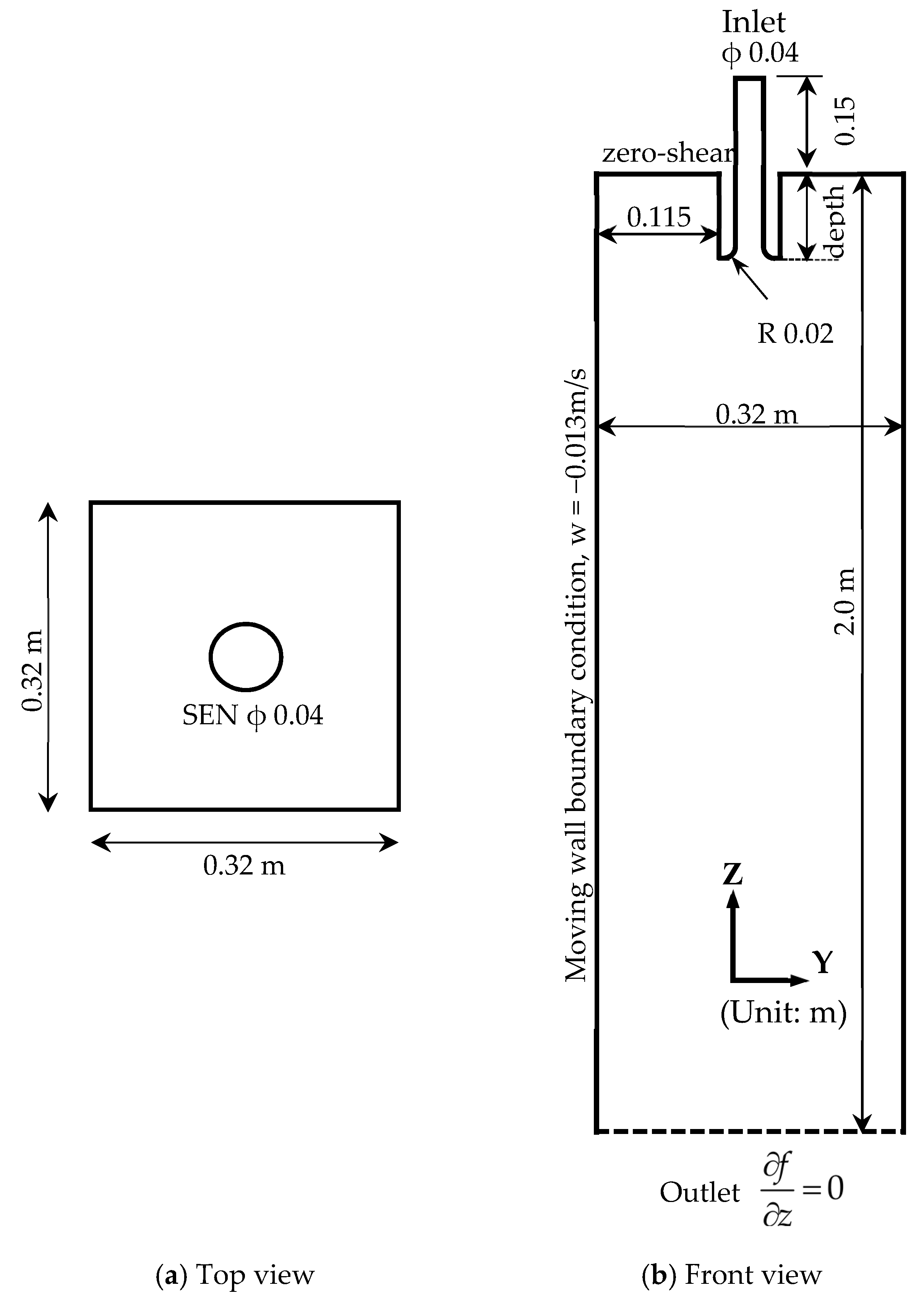
A three-dimensional mathematical model has been developed to describe the multiphase flow and heat transfer in a billet mold during the continuous casting of steel. The geometry and the dimension of the billet mold model is shown in Figure 1.
2.1. Model Assumption
The numerical model is based on the following assumptions:
- (1)
- Steel and slag behave as incompressible Newtonian fluids;
- (2)
- Solidification in the mold is not considered;
- (3)
- A constant molecular viscosity for steel and slag was assumed. This is due to the fact that the maximum temperature difference in the mold is only 30 K between 1788 K and 1818 K as the superheat of the steel. The viscosity change in this temperature range is not significant, and this can be seen from a previous study [10];
- (4)
- A constant steel and slag density was used. The temperature influence on the steel density change was accounted for in the source term of the momentum equation;
- (5)
- The SEN wall was assumed to be a smooth wall.
2.2. Transport Equations
The conservation of a general variable ф within a finite control volume can be expressed as a balance among the various processes, which tends to increase or decrease the variable values. The conservation equations, for example, continuity, volume fraction, momentum, turbulence equations, and energy equation, can be expressed by the following general equation [27]:
where the first term on the left-hand side is the instantaneous change of ϕ with time, the second term on the left-hand side represents the transport due to convection, and the first term on the right-hand side expresses the transport due to diffusion where is the diffusion coefficient with different values for different turbulence models, or the effective thermal conductivity. Furthermore, the second term on the right-hand side is the source term.
The steel-slag interface was tracked by the VOF model [28]. The sum of the slag phase fraction αslag and the steel phase fraction αsteel is equal to 1. The mixed material properties in the grid cell, where the interface exists, are required by the momentum equation and can be calculated by the following equations:
The realizable k-ε turbulence model, coupled with the Enhanced Wall Treatment model, was first used to produce an initial flow field [28]. Then, the Reynolds stress model (RSM) model combined with the Stress-Omega submodel was used to simulate the steel flow. The Stress-Omega submodel is good for modeling flows over the curved surfaces and swirling flows [28]. The Reynolds stress terms emerging from the Reynolds averaging of Navier-Stockes equations are directly solved to account for the possible anisotropic fluctuation in a swirling flow.
The temperature distribution in mold was obtained by solving the following energy equation [28]:
where E is energy in the unit of J, k is the thermal conductivity with the unit of W/(m·K), cp is the specific heat capacity in J/(kg·K), μt is the turbulent viscosity, Prt is the turbulent Prandtl Number, ρ is fluid density in kg/m3, p is pressure in Pa, and T is temperature in K. The steel density change and subsequent natural convection due to temperature variance was accounted for by the Boussinesq Model [29]. This model treats density as a constant value in all solved equations, except for the buoyancy in the momentum equation (it is normally put in source term) as follows:
where ρ0 is the (constant) density of the liquid steel with the unit of kg/m3, T0 is the operating temperature in K, and β is the thermal expansion coefficient of the liquid steel. The thermal properties of the fluids and some parameters are shown in Table 1.
2.3. Boundary Conditions
The velocity profile on the cross section of the cylindrical tundish SEN, which has been solved in a previous study [25], was used as the inlet boundary condition for the current simulation of the mold flow. This steel flow velocity at the inlet in Figure 1b has been presented in a previous study [26] and, thus, it is not repeated here. A nonslip boundary condition was imposed on the SEN wall. A zero-shear slip wall boundary condition was used at the mold surface. For the mold wall, a moving wall boundary condition with the velocity of 0.013 m/s in Z or downwards direction was used to account for the movement of the solidified shell in a real casting process. A fully developed flow condition is adopted at the mold outlet, where the normal gradients of all variables are set to zero. A constant steel temperature of 1818 K was used at the inlet, with a superheat of 30 K. A constant temperature of 1788 K was imposed on the solidified shell. An adiabatic condition was used both at the SEN wall and at the free surface.
2.4. Solution Method
The numerical model was solved using the commercial software ANSYS FLUENT 18.0® (ANSYS, Canonsburg, PA, USA). The numerical simulations were carried out based on 1.4 million grid cells to guarantee the grid-independent solution. A fine grid was used in the near-wall region, with the y+ value of the first grid layer around 1. The PISO (Pressure-Implicit with Splitting of Operators) scheme was used for the pressure-velocity coupling. Furthermore, the PRESTO (PREssure STaggering Option) method was adopted to discretize the pressure. The governing equations were discretized using a second order upwind scheme. The convergence criteria were as follow: The residuals of all dependent variables were smaller than 1 × 10⁻³ at each time step.
3. Results and Discussion
The multiphase flow and heat transfer in the mold with different SEN immersion depths were firstly solved by the realizable k-ε model with an Enhanced Wall Treatment for the first 75 s. After that, this solution was used as an initial condition for the RSM model calculation to 125 s for a developed flow field. The multiphysics in the mold with different SEN immersion depths were analyzed and compared in the following.
3.1. Steel Flow Phenomena
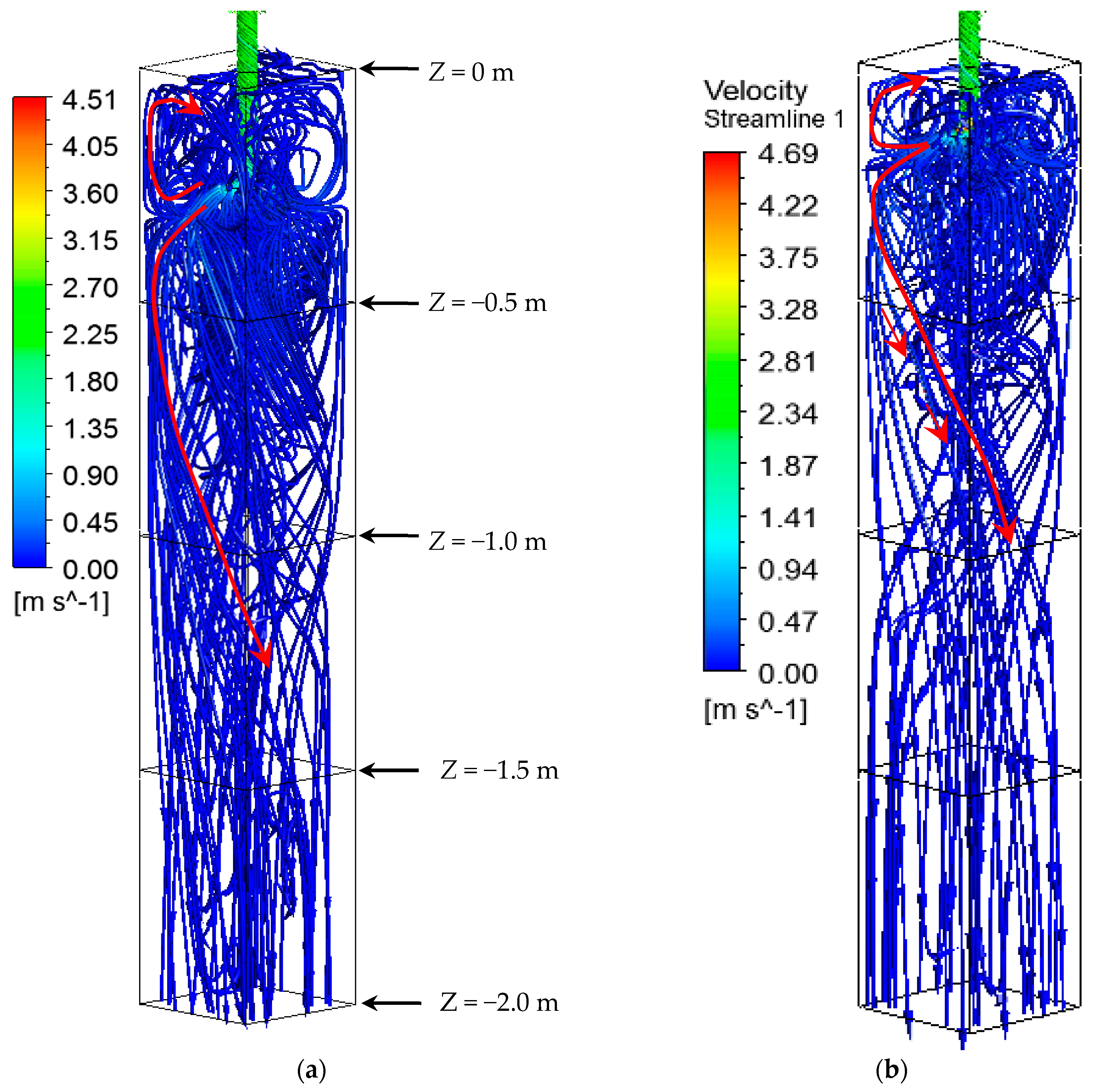
Figure 2 shows the steel flow path in the mold with different SEN immersion depths. It can be observed that the steel flow pattern in mold was similar for different SEN depths. It delivers the steel into the mold along the periphery of the SEN, which is in 360°. The SEN outlet flow moves towards the solidified shell after it flows out from the straight SEN due to the swirling flow effect, inducing a rotational steel flow momentum. After the steel stream reaches the solidified shell, a part of the steel flows downwards along the solidified shell with a horizontally rotational flow momentum, and another part of the steel moves upwards and towards the meniscus. Due to the difference in SEN immersion depth, the top rotational flow region near the meniscus was large when a large immersion depth of SEN was used. This should be beneficial for the decrease of the steel flow velocity, since the steel from SEN outlet needs a long distance to reach the steel-slag interface. Therefore, the current swirling flow tundish SEN can deliver high temperature steel uniformly distributed towards the solidified shell, no matter the change of the SEN depth.
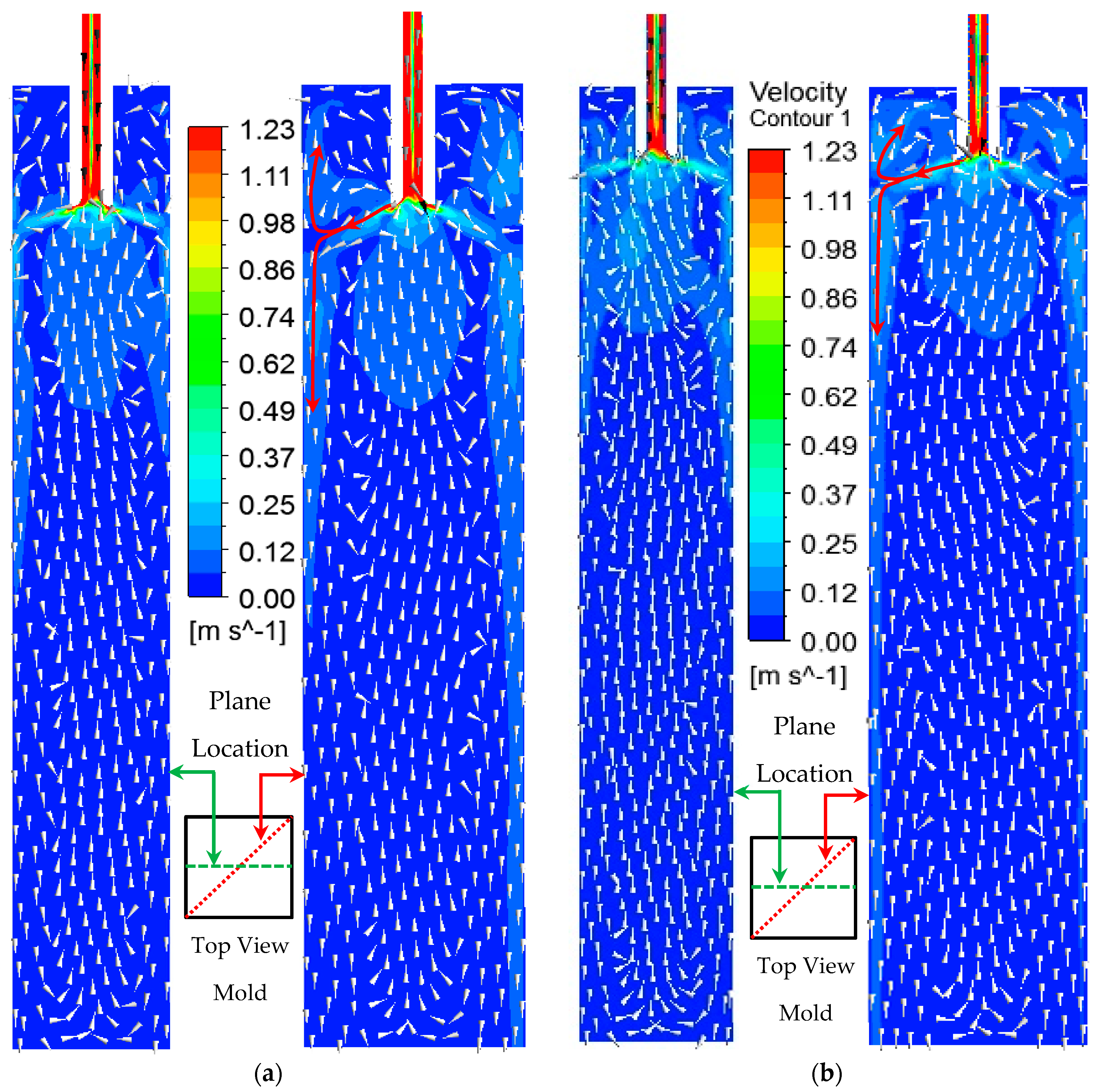
Figure 3 shows the velocity on the vertical plane located at the middle of the mold for different SEN immersion depths. It can be seen that the high velocity region was located at the solidification front in the mold. Steel moves downwards at the region near the solidified shell and it flows upwards in the center of the mold. The effect of the SEN depth is mainly on the steel flow velocity at the top of the mold. It can be seen that the region with a high steel flow velocity was reduced when a large SEN immersion depth was used. This is expected to reduce the risk of the slag entrainment at the steel–slag interface. When a large SEN immersion depth was used, the length of the SEN was increased. The dissipation of the rotational momentum was expected due to the friction of the SEN wall. However, it did not show significant influence on the steel flow in the mold below the height of the SEN outlet. Figure 4 shows a comparison of vertical velocity distributions along the line, with the mold depth of 1.5 m, for different SEN immersion depths. It can be seen that a large velocity with a magnitude of 0.03 m/s exists in the solidification front. This may be helpful to shear off the dendrites from the solidification interface and promotes the nucleate, which results in an enhancement of the transition from a columnar to equiaxed solidification [30]. Although the immersion depth of the SEN is different, the vertical velocity shows a similar distribution and magnitude. This means that the 10 cm difference in the immersion depth does not lead to a large change of the steel flow below the level of SEN outlet in mold.
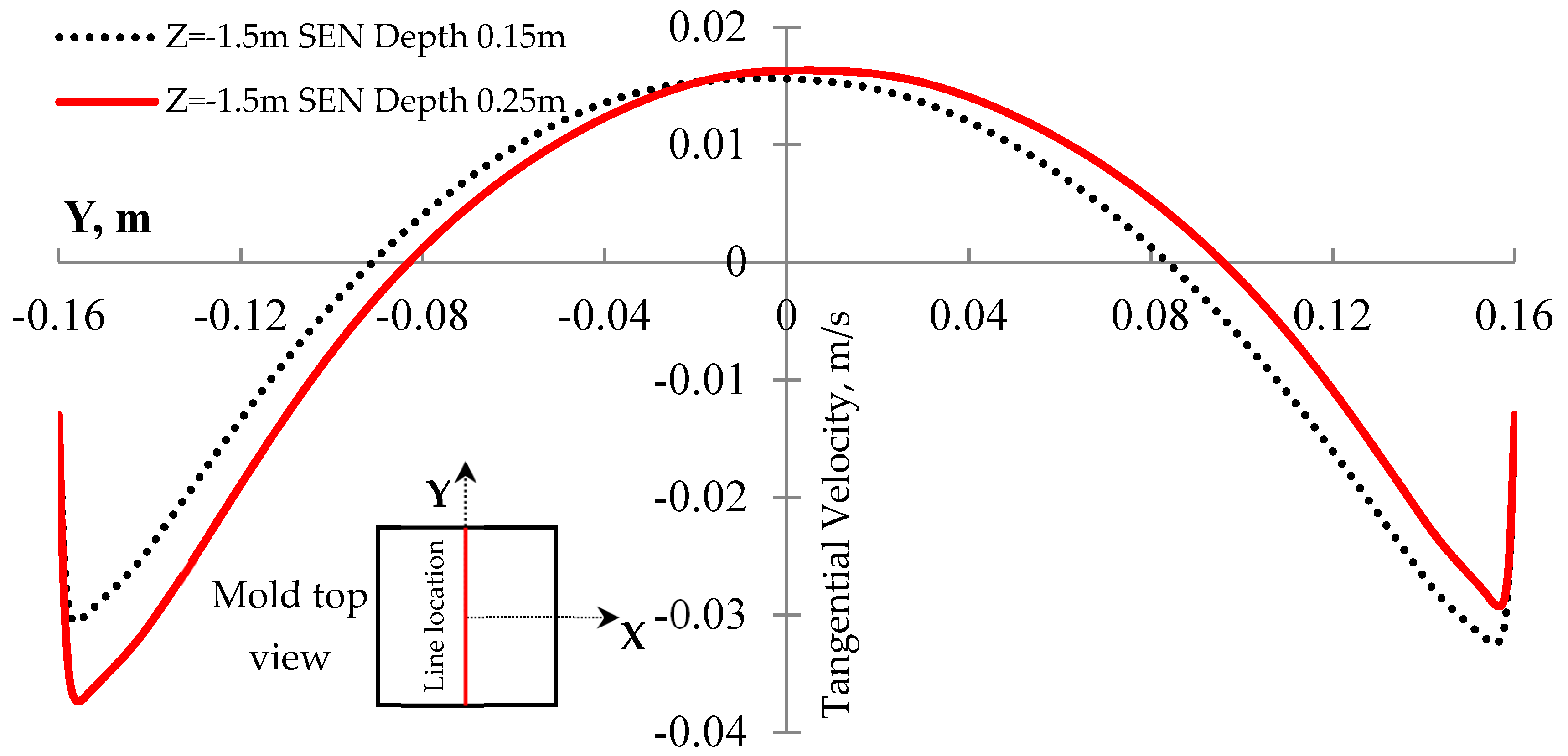
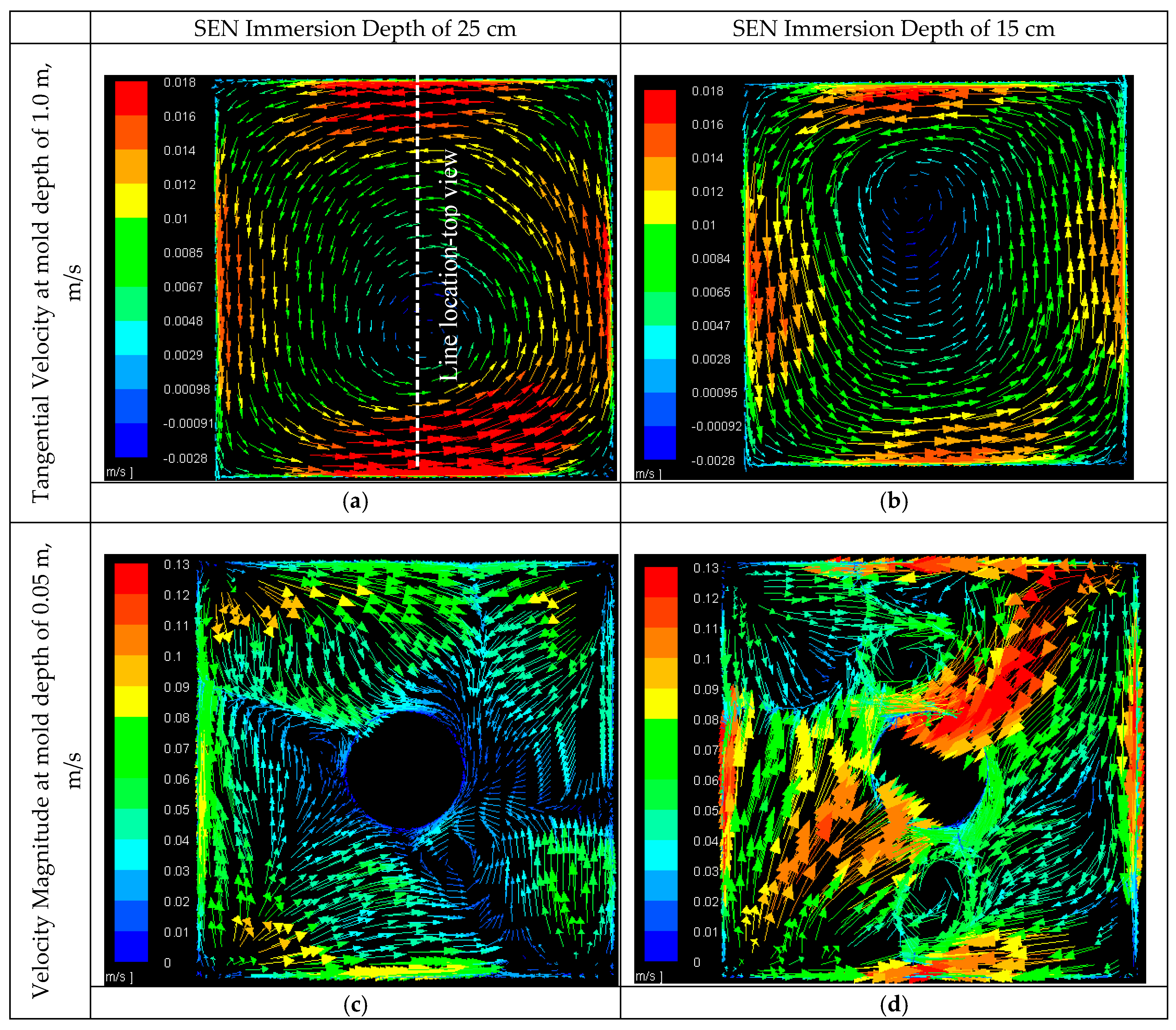
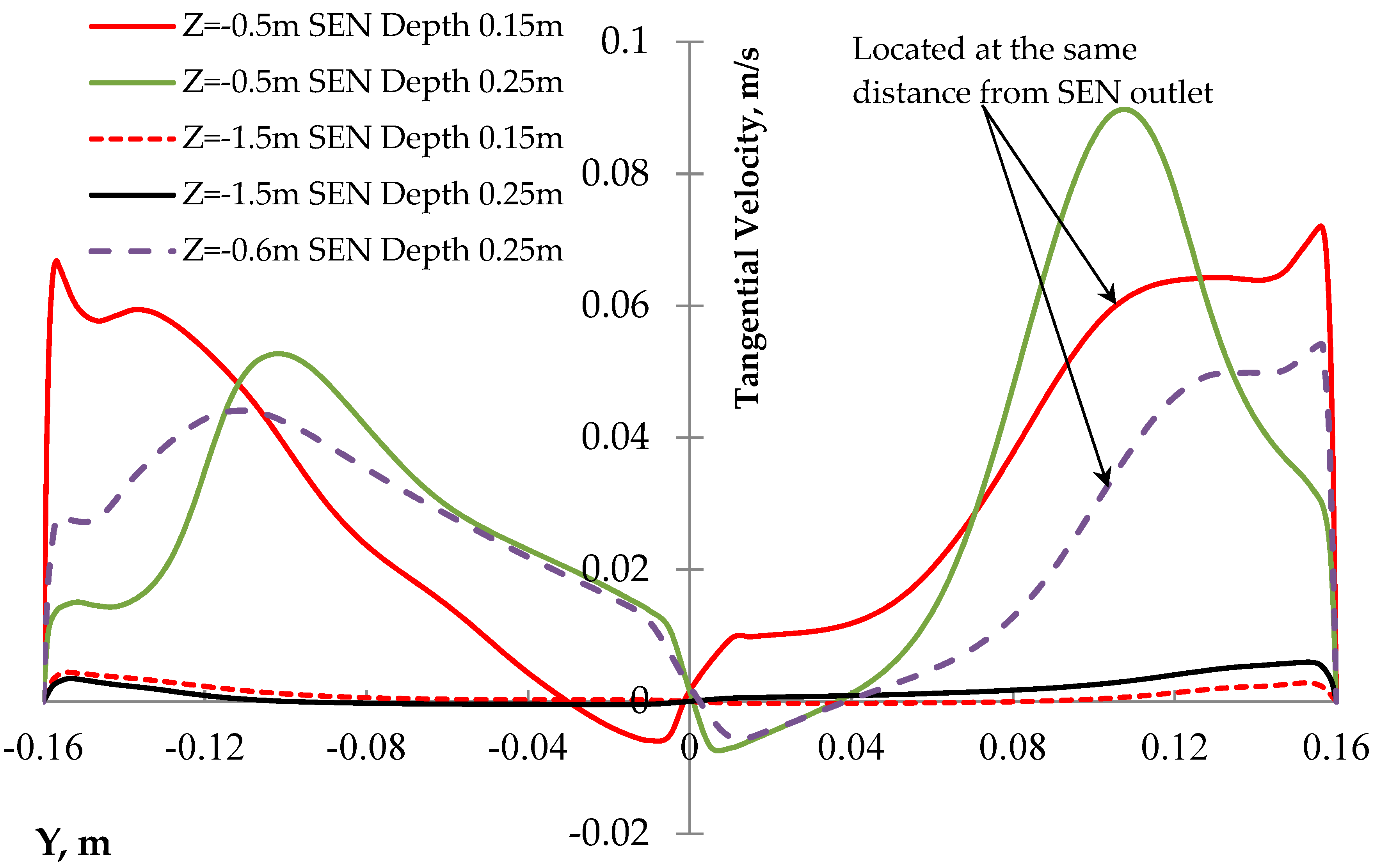
Figure 5 shows that the velocities of the steel flow at the different cross sections of for different SEN immersion depths. It can be seen from Figure 5a,b that the rotational flow developed very well in the mold depth of 1.0 m. A large tangential velocity was located at the solidification front, and the maximum tangential velocity can reach around 0.014 m/s near the solidified shell, which is a similar value for different SEN immersion depths. However, the rotational steel flow near the meniscus (Mold depth of 0.05 m) was not observed for these two SEN immersion depths. The steel flow magnitude in Figure 5c for the SEN immersion depth of 25 cm is smaller, compared to the immersion depth of 15 cm. It can be concluded that the rotational steel flow mainly develops in the deep mold rather than near the meniscus. Figure 6 shows the magnitude of the tangential velocity along different horizontal lines in different depths. The top view of the locations of these horizontal lines is shown in Figure 5a. It can be seen that for both cases, the maximum tangential velocity decreases when the steel moves downwards. The large tangential velocity region is located near the solidification front. In addition, at the location with the same distance from the SEN outlet (Z = −0.5 m and −0.6 m for SEN immersion depth of 15 cm and 25 cm, respectively), the maximum tangential velocity decreases with an increased SEN immersion depth. This is due to the fact that the swirling steel flow passed a larger SEN length when a larger immersion depth was used and the dissipation of SEN wall on the rotational steel flow momentum was avoided.
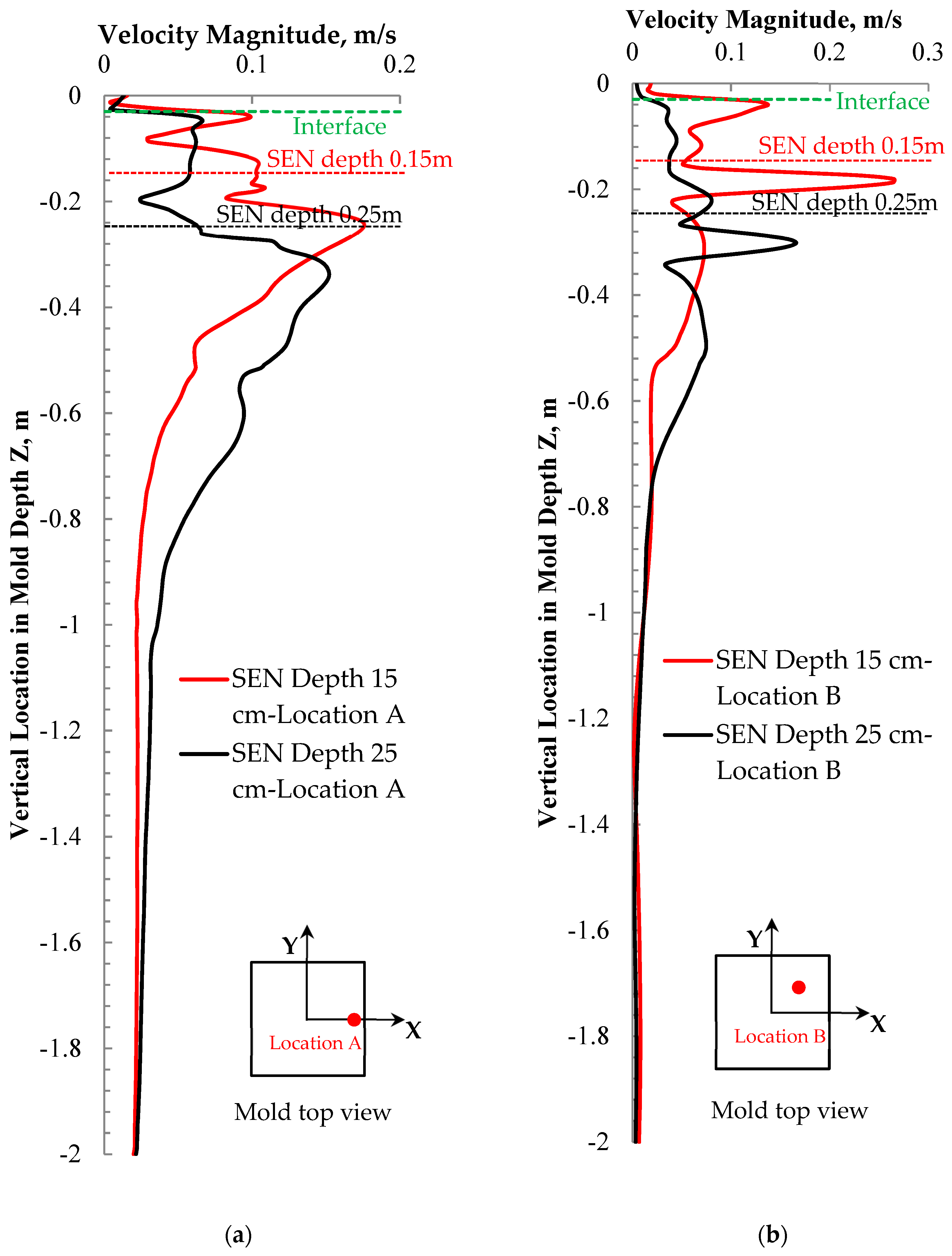
Figure 7 shows the velocity magnitude distribution along different lines in mold depth direction. Figure 7a is the velocity distribution at Location A with 1 cm away from the solidification shell. At the top of the mold, it can be seen that the velocity magnitude with a large SEN immersion depth is smaller than that with a small SEN immersion depth. This is helpful to reduce the risk of the slag entrainment. In the low part of the mold, the velocity near the solidification front is larger with a larger SEN immersion depth, and this is helpful for the formation of equiaxed crystals. In Figure 7b, the velocity distribution at Location B, which is close to the mold center, was presented. It can be seen that the major difference exists at the top of the mold, with a smaller velocity when a larger SEN depth was used. Furthermore, the velocity was similar at the location in deep mold. In summary, the general trend of the flow change when the SEN immersion depth was increased is that the velocity in the top mold decreased while the velocity at the low part of the mold increased.
3.2. Steel-Slag Interface Phenomena
One of the most important concerns about the swirling flow SEN is about the steel flow and heat transfer near the meniscus. Due to the existence of the swirling flow, the impingement jet flow in a conventional tundish casting disappeared [26]. The steel flow moves towards the solidification front, as shown in Figure 3. The induced steel flow in the meniscus region was increased, and this led to the heat transfer near the meniscus accelerating [26]. However, a large steel flow velocity near the meniscus region also illustrates a high risk of the slag entrainment. Therefore, it is very important to investigate the effect of the SEN immersion depth on the steel-slag interface behavior.
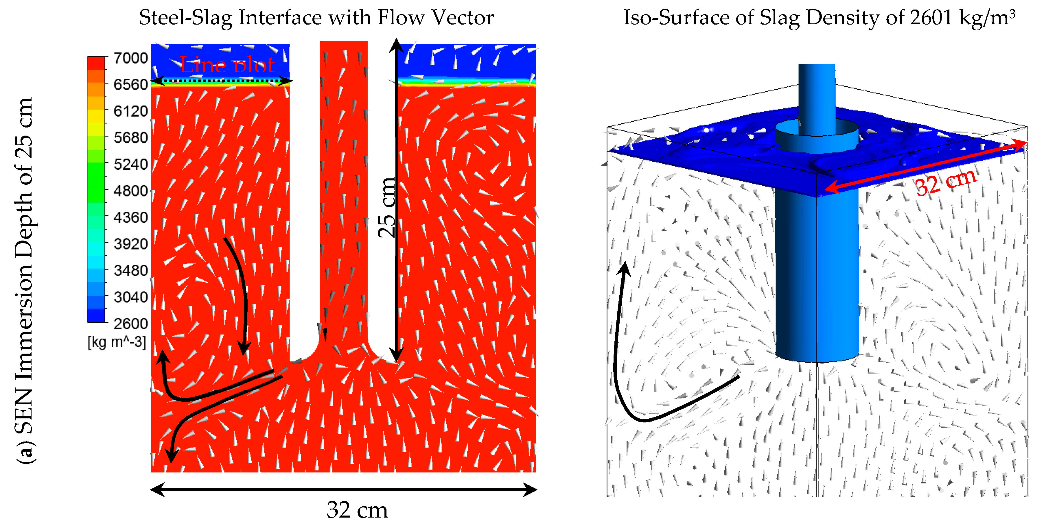
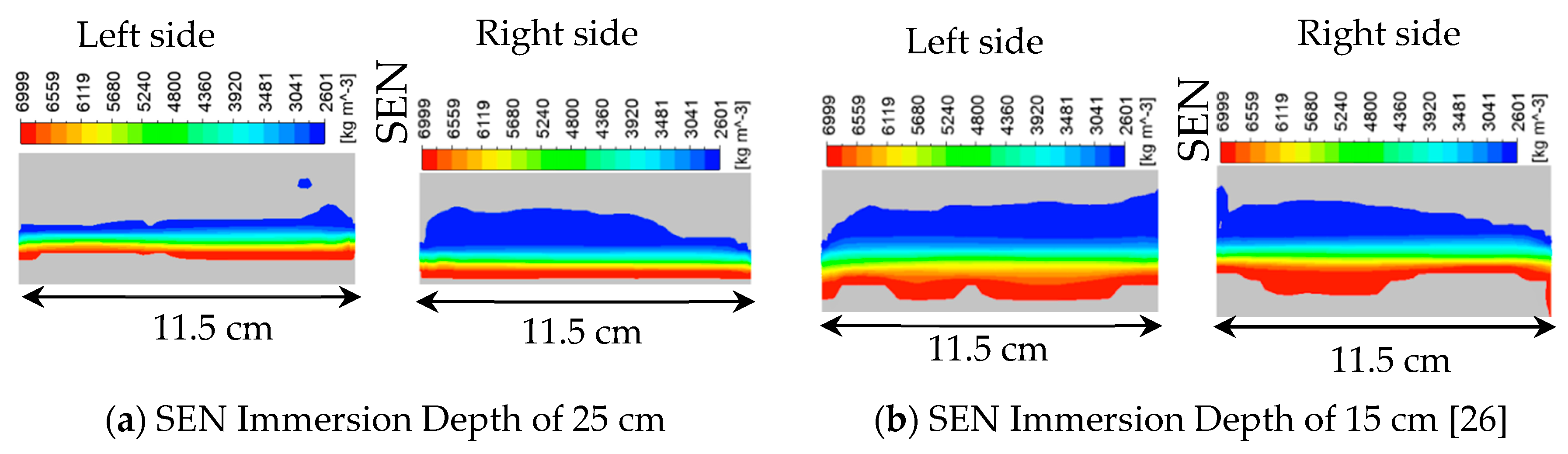
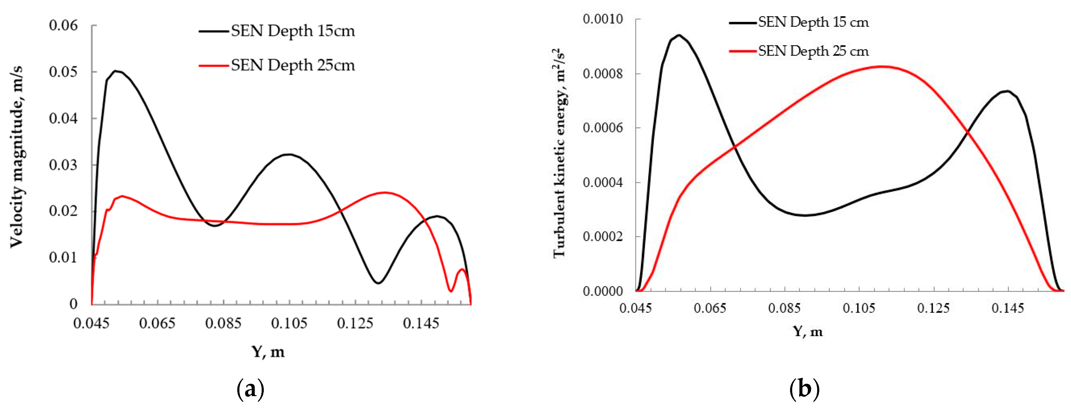
Figure 8 shows the steel-slag interface and the flow pattern in mold for different SEN immersion depths. It can be seen that the thickness of the steel-slag interface region was larger when a small immersion depth was used. This can also be seen from the iso-surface of the slag where the density of 2601 kg/m3 was plotted (the pure slag has the density of 2600 kg/m3). Above this iso-surface, almost pure slag existed. It can be seen that the steel flow here is strong to push the slag upwards. With a large SEN immersion depth, this phenomenon was alleviated. The difference comes from the upwards steel flow, indicated with the arrow in Figure 8, where the upwards steel flow is caused by the rotational steel flow from the swirling flow SEN. The VOF model cannot predict the sharp interface of two phases. Instead, a mixing region was predicted, and this mixing region does not mean that steel and slag are well mixed in reality. However, the thickness of the mixing region reflects the intensity of a steel-slag mixing. Figure 9 shows the enlarged view of the thickness of the steel-slag mixing region. It can be seen that the predicted thickness of the mixing region was much smaller when a larger SEN immersion depth was used. This means that the interface became stable. Figure 10 shows the distributions of the velocity magnitude and turbulent kinetic energy along the steel-slag interface for different SEN immersion depths. The location of the Line plot is shown in Figure 8. It can be seen that the velocity magnitude at the interface is decreased with an increased SEN immersion depth, with the maximum value decreasing from 0.05 m/s to 0.025 m/s. The maximum turbulent kinetic energy is similar for different SEN immersion depths, while its distribution shows a large difference. This may be due to the fact that the upwards steel flow arriving at the interface became more uniform when a large SEN immersion depth was used. In the case with M-EMS, the level fluctuation was also found to be increased [10,30]. The meniscus surface has a swirl flow and the meniscus level rises near the bloom strand wall and sinks around the SEN wall, which shows an inclined steel-slag interface [30]. Sometimes, a vortex formation near the SEN wall was found with M-EMS [31]. Therefore, the mold level fluctuation should be considered to make it as low as possible, both for M-EMS applications and for the use of swirling flow SEN. For the current swirling flow SEN, the interface flow can be controlled by the SEN immersion depth.
According to previous research [32], the slag entrainment into liquid steel may occur when the Weber number is greater than 12.3. The Weber number can be defined as:
where μl is the radial steel velocity, g is gravitational acceleration, and σ is the interfacial tension between steel and slag. A slag density value of 2600 kg/m3 was used, and the value of interfacial tension between the steel and the slag was set to 1.16 N/m. The maximum total velocity at the steel-slag interface in the mold, 0.05 m/s for immersion depth of 15 cm and 0.025 m/s for immersion depth of 25 cm, was used to calculate the Weber Number. The calculated maximum Weber number is around 0.8 and 0.2 for the small and large immersion depth, respectively. Therefore, the Weber number is still much smaller than 12.3, which means a small risk for the slag entrainment. Furthermore, 25 cm immersion depth can further decrease this risk. However, slag entrainment should be experimentally investigated in the future.
3.3. Temperature Field
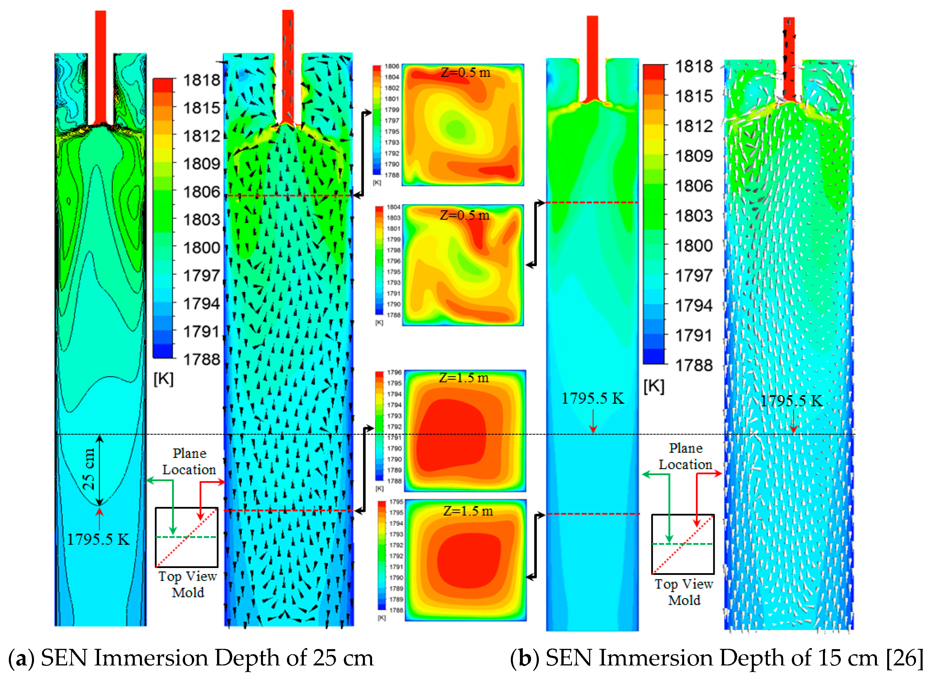
Steel temperature in the mold is very important, since it significantly influences the solidification structure, which in turn determines the product quality. The swirling flow SEN has proven that it can accelerate steel superheat removal [26]. This is good for the formation of equiaxed crystals. Figure 11 shows the temperature distribution in the mold with different SEN immersion depths. It can be seen that similar temperature distribution characteristics were observed for different SEN immersion depths. Due to the swirling flow effect, steel with a high temperature flows towards the solidified shell. It increased the temperature near the solidified shell as well as the temperature gradient there, while the core temperature of the billet was low. On the cross section at a depth of 0.5 m in the mold, the maximum temperatures for the immersion depths of 25 cm and 15 cm are 1806 and 1804 K, respectively. It can be seen that the high temperature region is not located in the center of the mold. These values decrease to 1796 K and 1795 K at the mold depth of 1.5 m, respectively. Here, the high temperature region was located in the mold center. This is due to the fact that the superheat of the steel near the solidification front can be removed fast, while that in the mold center cannot be easily dissipated. In addition, there are some differences induced by the increase of the immersion depth. The first issue is about the temperature near the meniscus, where a low temperature was observed when a large immersion depth was used. This is obviously due to the fact that the upwards steel flow near the solidified shell (as shown in Figure 3a) with a high temperature needs a long way to reach the meniscus and the superheat was dissipated along the way. Furthermore, due to a large immersion depth, the high temperature region moves downwards around 25 cm, compared to that with the SEN depth of 15 cm. This directly leads to the thickness of the low temperature region in the solidification front decreasing, as shown in Figure 11. Therefore, an increase in the SEN depth only slightly decreases the steel temperature near the meniscus and it makes the high temperature region in the mold move a bit downwards.
4. Conclusions
The effects of the SEN immersion depth on the multiphase flow and heat transfer in a mold with a new cylindrical tundish design for continuous casting were investigated using numerical simulations. The main conclusions were the following:
- Steel flow patterns are similar for different SEN immersion depths, with the flow direction towards the solidification front.
- An increase in the SEN immersion depth decreases the interfacial velocity and this reduces the risk of slag entrainment. The calculated Weber Number is 0.8 and 0.2 for the SEN depth of 15 cm and 25 cm, respectively. The steel flow velocity near the solidification front below the SEN outlet is increased with a large SEN immersion depth.
- The temperature distribution has a similar distribution characteristic. The high temperature region is located near the solidification front. Temperature near the meniscus was slightly decreased when the SEN immersion depth was increased.
- A large SEN immersion depth was recommended in order to reduce the slag entrainment. This will not reduce the steel flow velocity near the solidification front, nor will it significantly reduce the temperature near the meniscus.
Author Contributions
P.N. and L.T.I.J. designed the paper; P.N. and M.E. did the numerical simulation; all the authors analyzed and discussed the results; P.N. wrote the paper; L.T.I.J., T.Z. and P.G.J. revised the paper.
Funding
The authors want to thank the National Natural Science Foundation of China (Grant No. 51704062) for the support on this work.
Conflicts of Interest
The authors declare no conflict of interest.
References
- Szekely, J.; Yadoya, R.T. The physical and mathematical modelling of the flow field in the mold region of continuous casting systems. Part II. The mathematical representation of the turbulence flow field. Metall. Mater. Trans. 1973, 4, 1379–1388. [Google Scholar] [CrossRef]
- Xu, M.; Zhu, M. Transport phenomena in a Beam-Blank continuous casting mold with two types of submerged entry nozzle. ISIJ Int. 2015, 55, 791–798. [Google Scholar] [CrossRef]
- Thomas, B.G.; Mika, L.J.; Najjar, F.M. Simulation of fluid flow inside a continuous slab-casting machine. Metall. Mater. Trans. B 1990, 21, 387–400. [Google Scholar] [CrossRef]
- Calderon-Ramos, I.; Morales, R.D.; Garcia-Hernandez, S.; Ceballos-Huerta, A. Effects of immersion depth on flow turbulence of liquid steel in a slab mold using a nozzle with upward angle rectangular ports. ISIJ Int. 2014, 54, 1797–1806. [Google Scholar] [CrossRef]
- Calderon-Ramos, I.; Morales, R.D.; Salazar-Campoy, M. Modeling flow turbulence in a continuous casting slab mold comparing the use of two bifurcated nozzles with square and circular ports. Steel Res. Int. 2015, 86, 1610–1621. [Google Scholar] [CrossRef]
- Calderon-Ramos, I.; Morales, R.D. The role of submerged entry nozzle port shape on fluid flow turbulence in a slab mold. Metall. Mater. Trans. B 2015, 46, 1314–1325. [Google Scholar] [CrossRef]
- Salazar-Campoy, M.; Morales, R.D.; Najera-Bastida, A.; Cedillo-Hernandez, V.; Delgado-Pureco, J.C. A physical model to study the effects of nozzle design on dense two-phase flows in a slab mold casting ultra-low carbon steels. Metall. Mater. Trans. B 2017, 48, 1376–1389. [Google Scholar] [CrossRef]
- Sun, H.; Zhang, J. Macrosegregation improvement by swirling flow nozzle for bloom continuous castings. Metall. Mater. Trans. B 2014, 45, 936–946. [Google Scholar] [CrossRef]
- Sun, H.; Li, L. Application of swirling flow nozzle and investigation of superheat dissipation casting for bloom continuous casing. Ironmak. Steelmak. 2016, 43, 228–233. [Google Scholar] [CrossRef]
- Fang, Q.; Ni, H.; Zhang, H.; Wang, B.; Lv, Z. The effects of a submerged entry nozzle on flow and initial solidification in a continuous casting bloom mold with electromagnetic stirring. Metals 2017, 7, 146. [Google Scholar] [CrossRef]
- Thomas, B.G.; Dennisov, A.; Bai, H. Behavior of Argon Bubbles during Continuous Casting of Steel. In Proceedings of the 80th Steelmaking Conference, Chicago, IL, USA, 13–16 April 1997. [Google Scholar]
- Wang, Y.; Zhang, L. Fluid flow-related transport phenomena in steel slab continuous casting strands under electromagnetic brake. Metall. Mater. Trans. B 2011, 42, 1319–1351. [Google Scholar] [CrossRef]
- Yu, H.; Zhu, M. Numerical simulation of the effects of electromagnetic brake and argon gas injection on the three-dimensional multiphase flow and heat transfer in slab continuous casting mold. ISIJ Int. 2008, 48, 584–591. [Google Scholar] [CrossRef]
- Yokoya, S.; Takagi, S.; Iguchi, M.; Asako, Y.; Westoff, R.; Hara, S. Swirling effect in immersion nozzle on flow and heat transport in billet continuous casting mold. ISIJ Int. 1998, 38, 827–833. [Google Scholar] [CrossRef]
- Yokoya, S.; Jönsson, P.G.; Sasaki, K.; Tada, K.; Takagi, S.; Iguchi, M. The effect of swirl flow in an immersion nozzle on the heat and fluid flow in a billet continuous casting mold. Scand. J. Metall. 2004, 33, 22–28. [Google Scholar] [CrossRef]
- Kholmatov, S.; Takagi, S.; Jonsson, L.; Jönsson, P.; Yokoya, S. Development of flow field and temperature distribution during changing divergent angle of the nozzle when using swirl flow in a square continuous casting billet mold. ISIJ Int. 2007, 47, 80–87. [Google Scholar] [CrossRef]
- Kholmatov, S.; Takagi, S.; Jonsson, L.; Jönsson, P.; Yokoya, S. Effect of nozzle angle on flow field and temperature distribution in a billet mold when using swirl flow. Steel Res. Int. 2008, 79, 31–39. [Google Scholar] [CrossRef]
- Tsukaguchi, Y.; Hayashi, H.; Kurimoto, H.; Yokoya, S.; Marukawa, K.; Tanaka, T. Development of swirling-flow submerged entry nozzles for slab casting. ISIJ Int. 2010, 50, 721–729. [Google Scholar] [CrossRef]
- Geng, D.; Lei, H.; He, J.; Liu, H. Effect of electromagnetic swirling flow in slide-gate SEN on flow field in square billet continuous casting mold. Acta Metall. Sin. 2012, 25, 347–356. [Google Scholar]
- Wondrak, Th.; Eckert, S.; Galindo, V.; Gerbeth, G.; Stefani, F.; Timmel, K.; Peyton, A.J.; Yin, W.; Riaz, S. Liquid metal experiments with swirling flow submerged entry nozzle. Ironmak. Steelmak. 2012, 39, 1–9. [Google Scholar] [CrossRef]
- Li, D.; Su, Z.; Chen, J.; Wang, Q.; Yang, Y.; Nakajima, K.; Marukaw, K.; He, J. Effects of electromagnetic swirling flow in submerged entry nozzle on square billet continuous casting of steel process. ISIJ Int. 2013, 53, 1187–1194. [Google Scholar] [CrossRef]
- Yang, Y.; Jönsson, P.G.; Ersson, M.; Su, Z.; He, J.; Nakajima, K. The Influence of swirl flow on the flow field, temperature field and inclusion behavior when using a half type electromagnetic swirl flow generator in a submerged entry and mold. Steel Res. Int. 2015, 86, 1312–1327. [Google Scholar] [CrossRef]
- Ni, P.; Jonsson, L.; Ersson, M.; Jönsson, P. A new tundish design to produce a swirling flow in the SEN during continuous casting of steel. Steel Res. Int. 2016, 87, 1356–1365. [Google Scholar] [CrossRef]
- Ni, P.; Jonsson, L.; Ersson, M.; Jönsson, P. Non-Metallic inclusion behaviors in a new tundish and SEN design using a swirling flow during continuous casting of steel. Steel Res. Int. 2017, 88, 1600155. [Google Scholar] [CrossRef]
- Ni, P.; Wang, D.; Jonsson, L.; Ersson, M.; Zhang, T.; Jönsson, P. Numerical and physical study on a cylindrical tundish design to produce a swirling flow in the SEN during continuous casting of steel. Metall. Mater. Trans. B 2017, 48, 2695–2706. [Google Scholar] [CrossRef]
- Ni, P.; Ersson, M.; Jonsson, L.; Zhang, T.; Jönsson, P. Numerical study on the influence of a swirling flow tundish on multiphase flow and heat transfer in mold. Metals 2018, 8, 368. [Google Scholar] [CrossRef]
- Patankar, S.V. Numerical Heat Transfer and Fluid Flow; Hemispere Publishing Corporation: New York, NY, USA, 1980. [Google Scholar]
- ANSYS Fluent Theory Guide, Release 18.0; ANSYS: Canonsburg, PA, USA, 2017.
- ANSYS Fluent User’s Guide, Release 18.0; ANSYS: Canonsburg, PA, USA, 2017.
- Liu, H.; Xu, M.; Qiu, S.; Zhang, H. Numerical simulation of fluid flow in a round bloom mold with In-Mold rotary electromagnetic stirring. Metall. Mater. Trans. B 2012, 43, 1657–1675. [Google Scholar] [CrossRef]
- Willers, B.; Barna, M.; Reiter, J.; Eckert, S. Experimental investigations of rotary electromagnetic mould stirring in continuous casting using a cold liquid metal model. ISIJ Int. 2017, 57, 468–477. [Google Scholar] [CrossRef]
- Jonsson, L.; Jönsson, P. Modeling of fluid flow conditions around the slag/metal interface in a gas-stirred ladle. ISIJ Int. 1996, 36, 1127–1134. [Google Scholar] [CrossRef]
Figure 1.
Geometry of the casting mold, (a) top view of the billet mold and (b) front view of the mold.
Figure 1.
Geometry of the casting mold, (a) top view of the billet mold and (b) front view of the mold.

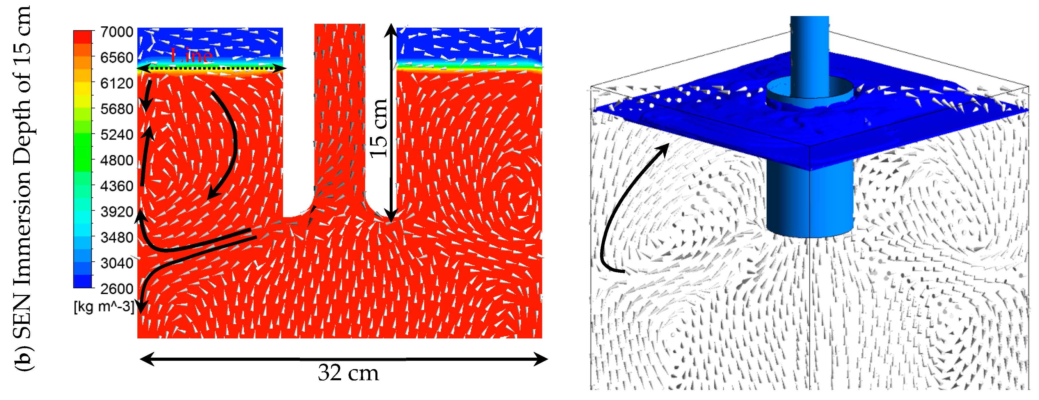
Figure 2.
Comparison of steel flow paths in mold, (a) SEN immersion depth of 25 cm and (b) SEN immersion depth of 15 cm [26].
Figure 2.
Comparison of steel flow paths in mold, (a) SEN immersion depth of 25 cm and (b) SEN immersion depth of 15 cm [26].

Figure 3.
Steel flow velocity in the vertical middle plane of the mold, (a) SEN immersion depth of 0.25 m and (b) SEN immersion depth of 0.15 m [26]. (Arrows are the steel flow directions).
Figure 3.
Steel flow velocity in the vertical middle plane of the mold, (a) SEN immersion depth of 0.25 m and (b) SEN immersion depth of 0.15 m [26]. (Arrows are the steel flow directions).

Figure 4.
Vertical steel flow velocity along horizontal lines in different mold depths.

Figure 5.
Velocities on different cross sections of the mold at different mold depths and SEN immersion depths, (a) tangential velocity for SEN depth of 0.25 m and mold depth of 1.0 m, (b) tangential velocity for the SEN depth of 0.15 m and mold depth of 1.0 m, (c) velocity magnitude for the SEN depth of 0.25 m and mold depth of 0.05 m and (d) velocity magnitude for the SEN depth of 0.15 m and mold depth of 0.05 m.

Figure 6.
Tangential velocity distribution along different horizontal lines in different mold depths.
Figure 6.
Tangential velocity distribution along different horizontal lines in different mold depths.

Figure 7.
Total velocity distribution along different lines in mold depth direction, (a) Location A with 1 cm away from the wall and (b) Location B in the center of the top-right one quarter cross section.
Figure 7.
Total velocity distribution along different lines in mold depth direction, (a) Location A with 1 cm away from the wall and (b) Location B in the center of the top-right one quarter cross section.

Figure 8.
Steel-slag interface with steel flow vectors.


Figure 9.
Enlarged interface region in Figure 8, with a density range from pure slag to pure steel.
Figure 9.
Enlarged interface region in Figure 8, with a density range from pure slag to pure steel.

Figure 10.
(a) Velocity magnitude at the steel-slag interface and (b) turbulent kinetic energy at the steel-slag interface.
Figure 10.
(a) Velocity magnitude at the steel-slag interface and (b) turbulent kinetic energy at the steel-slag interface.

Figure 11.
Temperature distribution in mold for different SEN immersion depths.


Table 1.
Thermal properties of the steel and slag.
| Parameters | Symbols | Steel | Slag |
|---|---|---|---|
| Density, kg/m3 | ρ0 | 7000 | 2600 |
| Viscosity, kg/(m·s) | µ | 0.0064 | 0.09 |
| Thermal conductivity, w/(m·K) | k | 35 | 1.1 |
| Specific heat, J/(kg·K) | cp | 628 | 1200 |
| Thermal expansion Coefficient, 1/K | β | 10−4 | - |
| Interface tension, N/m | σ | 1.6 | |
| Operating Temperature, K | To | 1788 | |
| Turbulent Prandtl Number | Prt | 0.85 | |
© 2018 by the authors. Licensee MDPI, Basel, Switzerland. This article is an open access article distributed under the terms and conditions of the Creative Commons Attribution (CC BY) license (http://creativecommons.org/licenses/by/4.0/).
Share and Cite
MDPI and ACS Style
Ni, P.; Ersson, M.; Jonsson, L.T.I.; Zhang, T.-A.; Jönsson, P.G. Effect of Immersion Depth of a Swirling Flow Tundish SEN on Multiphase Flow and Heat Transfer in Mold. Metals 2018, 8, 910. https://doi.org/10.3390/met8110910
AMA Style
Ni P, Ersson M, Jonsson LTI, Zhang T-A, Jönsson PG. Effect of Immersion Depth of a Swirling Flow Tundish SEN on Multiphase Flow and Heat Transfer in Mold. Metals. 2018; 8(11):910. https://doi.org/10.3390/met8110910
Chicago/Turabian StyleNi, Peiyuan, Mikael Ersson, Lage T. I. Jonsson, Ting-An Zhang, and Pär Göran Jönsson. 2018. "Effect of Immersion Depth of a Swirling Flow Tundish SEN on Multiphase Flow and Heat Transfer in Mold" Metals 8, no. 11: 910. https://doi.org/10.3390/met8110910
Note that from the first issue of 2016, this journal uses article numbers instead of page numbers. See further details here.