Article

Influence of Solution Treatment Temperature on Microstructural Properties of an Industrially Forged UNS S32750/1.4410/F53 Super Duplex Stainless Steel (SDSS) Alloy

by
Vasile Dănuț Cojocaru
1,
Nicolae Șerban
1,
Mariana Lucia Angelescu
1,*,
Mihai Cosmin Cotruț
1,
Elisabeta Mirela Cojocaru
1 and
Adrian Nicolae Vintilă
2
1
Materials Science and Engineering Faculty, University POLITEHNICA of Bucharest, Bucharest 060042, Romania
2
FORJA ROTEC Ltd., Buzău 120224, Romania
*
Author to whom correspondence should be addressed.
Metals 2017, 7(6), 210; https://doi.org/10.3390/met7060210
Submission received: 27 March 2017 / Revised: 30 May 2017 / Accepted: 2 June 2017 / Published: 7 June 2017

Abstract

:
In this present study, the influence of solution annealing temperature on microstructural properties of a forged Super Duplex Stainless Steel (SDSS) was investigated by SEM-BSE (Scanning Electron Microscopy-Backscattered Electrons) and SEM-EBSD (Scanning Electron Microscopy-Electron Backscatter Diffraction) techniques. A brief solution treatment was applied to the forged super duplex alloy, at different temperatures between 800 °C and 1100 °C, with a constant holding time of 0.6 ks (10 min). Microstructural characteristics such as nature, weight fraction, distribution and morphology of constituent phases, average grain-size and grain misorientation were analysed in relation to the solution annealing temperature. Experimental results have shown that the constituent phases in the SDSS alloy are δ-Fe, γ-Fe and σ (Cr-Fe) and that their properties are influenced by the solution treatment temperature. SEM examinations revealed microstructural modifications induced by the Cr rich precipitates along the δ/γ and δ/δ grain boundaries, which may significantly affect the toughness and the corrosion resistance of the alloy. Solution annealing at 1100 °C led to complete dissolution of σ (Cr-Fe) phase, the microstructure being formed of primary δ-Fe and γ-Fe. The orientation relationship between δ/δ, γ/γ and δ/γ grains was determined by electron back scattering diffraction (EBSD). Both primary constituent phase’s microhardness and global microhardness were determined.

1. Introduction

Super Duplex Stainless Steels (SDSS) are known to exhibit high mechanical and corrosion resistance properties, which recommend them to be used in hard exploitation conditions, such as those encountered in oil, chemical, marine and nuclear industrial fields [1,2,3,4,5,6,7,8]. A less favourable aspect is the poor hot ductility of SDSS, which makes their hot working to be very difficult [9,10,11]. Besides chemical composition, thermo-mechanical treatments have a significant influence on the properties of SDSS, hence the importance of studying this subject in order to improve their behaviour during industrial processing and exploitation. It has been shown that the high alloying content in these steels increases the risk of precipitation of intermetallic phases, with a negative effect on the corrosion resistance and ductility [5,6,7]. For example, it was reported that precipitation of sigma phase determines the formation of Cr-depleted zones [12,13], leading to a decrease of mechanical and corrosion resistance and finally to premature failure [14,15,16,17,18,19,20]. The microstructural evolution of SDSS after hot deformation and subsequent solution annealing is very important for preventing the formation of deleterious intermetallic phases and, therefore, the easiest solution to achieve the desired properties seems to be a proper control of thermo-mechanical treatment [21,22,23,24,25]. The solution annealing improves the mechanical and corrosion characteristics of SDSS by dissolving the secondary deleterious phases at high temperatures, but also the annealing temperature can affect the δ-Fe and γ-Fe phases proportion, modifying this way the alloying elements partitioning in the two phases (δ-Fe being enriched in Cr and Mo and γ-Fe in N) and consequently the corrosion resistance of each phase [1,26]. In this regard, studying the correlation between the solution treatment parameters and microstructural characteristics can be very helpful [27,28,29].
The present work aims to study the microstructural evolution during a brief solution heat treatment applied to a commercial UNS S32750/1.4410/F53 SDSS alloy, which was previously forged in industrial conditions, with the purpose of improving the forging process and the quality of forged products. By varying the solution treatment temperature between 800 °C and 1100 °C, several microstructural states were obtained. The holding time was always the same, 0.6 ks (10 min). The component phases in different conditions of thermo-mechanical processing were identified and characterized by means of SEM-BSE (Scanning Electron Microscopy-Backscattered Electrons) and SEM-EBSD (Scanning Electron Microscopy-Electron Backscatter Diffraction) techniques, in order to establish the influence of solution annealing temperature on microstructural properties.

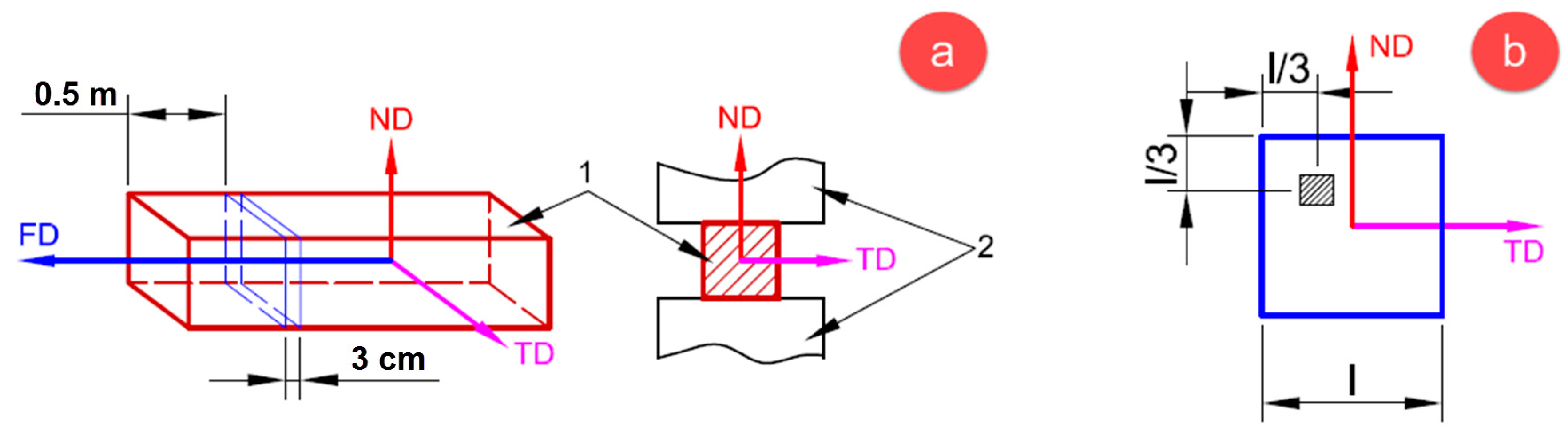
2. Materials and Methods

The investigated UNS S32750/1.4410/F53 Super Duplex Stainless Steel (SDSS) alloy has been industrially forged in the 1250–1050 °C temperature range, starting from an initial polygonal ingot with an equivalent diameter of about 800 mm and a total mass of 8.6 t, at FORJA ROTEC Ltd., Buzau, Romania. The industrial forging process was performed in 7 consecutive steps, with 6 intermediary reheating stages, until a final 350 mm square section bar was obtained. After forging, the furnace was turned off and the forged bar was introduced inside and slowly cooled, up to the ambient temperature.
After forging, the bar is designated for the production of special flanges for petrochemical industry, by mechanical machining. The chemical composition (wt %) of the investigated SDSS alloy UNS S32750/1.4410/F53, determined by optical emission spectrometry (OES), was C 0.023, Si 0.522, Mn 0.998, P 0.021, S 0.012, Cr 24.864, Ni 7.102, Mo 4.216, Cu 0.322, W 0.795, N 0.284 and balance Fe.
From the initial forged bar, at 0.5 m from the forward end, a slice of approx. 3 cm thickness was cut (Figure 1a). From this slice, at 1/3 from each slice corner, 5 cm × 5 cm sampling areas were cut, in order to obtain samples for further processing by solution treating, with the aim of investigating the microstructural changes registered (Figure 1b). Parallelepiped shaped samples, with approx. dimensions of 20 mm × 10 mm × 5 mm, were used for solution treating processing.
The solution treatment temperatures were chosen taking into account that at temperatures below 1100 °C secondary phases may precipitate, as σ (Cr-Fe), Cr2N and γ2-Fe (secondary austenite), with high negative effects on the corrosion resistance of SDSS alloy [25,26,27,28,29]. Four solution treatment temperatures were selected: 800 °C, 900 °C, 1000 °C and 1100 °C. Considering the sample dimensions and the rapid dissolution kinetics of deleterious secondary phases [14], the solution treatment duration was set to 10 min (0.6 ks) for all treatments, including also the transitory time needed to reach the heat treatment temperature (the samples being fed into the preheated furnace) and the time required for temperature homogenization. At the end of heating, the temperature of each sample was verified by using a laser pyrometer and, after that, the samples were water-quenched (WQ), to preserve the microstructure from high-temperature to ambient-temperature and also to limit intermetallic precipitates formation [30,31,32,33].
Samples from all processed states (as-forged; solution-treated at 800 °C for 0.6 ks; solution-treated at 900 °C for 0.6 ks; solution-treated at 1000 °C for 0.6 ks and solution-treated at 1100 °C for 0.6 ks) were cut and metallographically polished for microstructural analysis. The samples were hot-mounted in conductive phenolic powder (150 °C—0.42 ks) and metallographically grinded down from 180 to 1200-grit SiC paper, in 6 steps (60 s/step), then polished with 6 μm and 1 μm polycrystalline diamond suspension (180 s/step), followed by super-polishing with 0.5 μm and 0.05 μm alumina suspension (120 s/step) and finally vibro-polishing with 0.02 μm colloidal silica (3.6 ks).
The microstructure was investigated by SEM-BSE and SEM-EBSD techniques, with the purpose of observing the microstructural changes produced during the thermo-mechanical processing. The SEM microscope—TESCAN Vega II-XMU SEM (TESCAN, Brno, Czech Republic) was fitted with a BRUKER Quantax e-Flash EBSD detector. The following parameters were used: 320 × 240 pixels resolution, 10 ms acquisition time/pixel, 1 × 1 binning size and less than 0.5% zero solutions.
In order to identify all phases, the SEM-EBSD analysis was applied. The γ-Fe phase was indexed in Fm-3m-225 cubic system, with a lattice parameter a = 3.66 Å, the δ-Fe phase was indexed in Im-3m-229 cubic system, with a lattice parameter a = 2.86 Å and the σ (Cr-Fe) phase was indexed in P42/mnm-136 tetragonal system, with lattice parameters a = 8.80 Å and c = 4.54 Å. No other phases (chi, nitrides, carbides, etc.) were detected for the investigated UNS S32750/1.4410/F53 SDSS alloy.
In order to compute the weight fractions of δ-Fe, γ-Fe and σ (Cr-Fe) phases, the following procedure was applied: for each microstructural state, 10 arbitrary SEM-EBSD images were acquired at identical magnification, with the following parameters: EBSD 160 × 120 pixels resolution, 5 ms acquisition time/pixel, 1 × 1 binning size; in each SEM-EBSD image the fractions of phases were quantified; the data obtained was statistically analysed, to determine the standard deviation for each component phase.
All samples (as-forged and solution-treated for 0.6 ks at 800 °C, 900 °C, 1000 °C and 1100 °C) were also microhardness-investigated using a Wilson-Wolpert 401MVA equipment (Wilson Hardness, Norwood, MA, USA.), by applying testing forces of 10 gf (HV0.01) for evaluating the microhardness of γ-Fe and δ-Fe phases and 100 gf (HV0.1) for evaluating the global microstructure microhardness and using a dwell time of 30 s for each test. In all cases, a number of 15 measurements were performed and after eliminating the minimum and the maximum values obtained, using the remaining data the average value of Vickers microhardness was calculated.

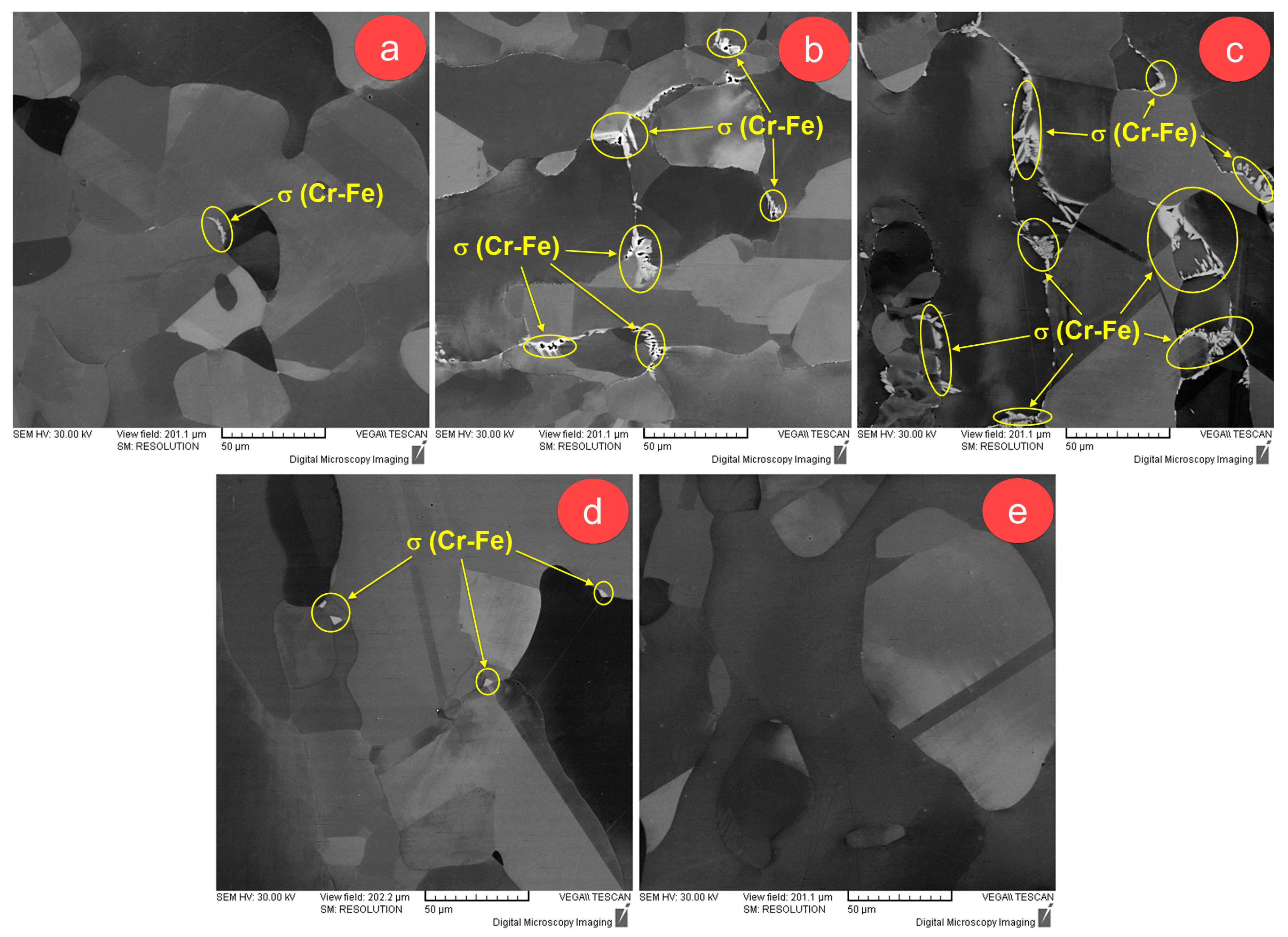
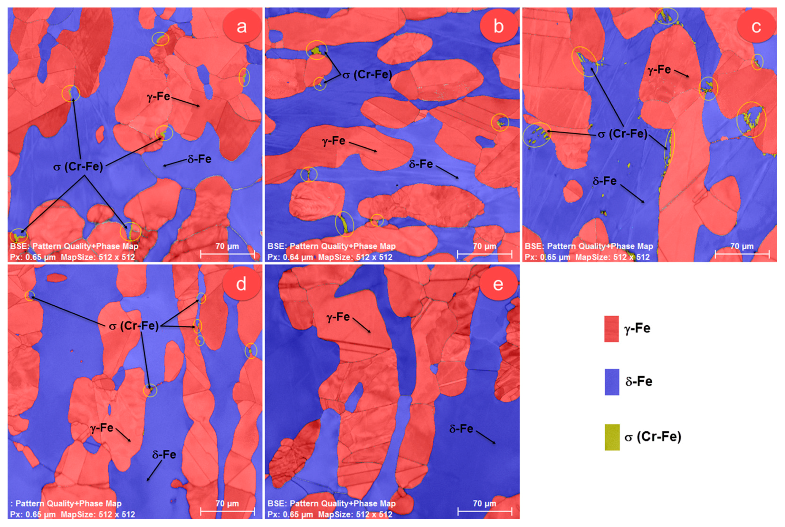
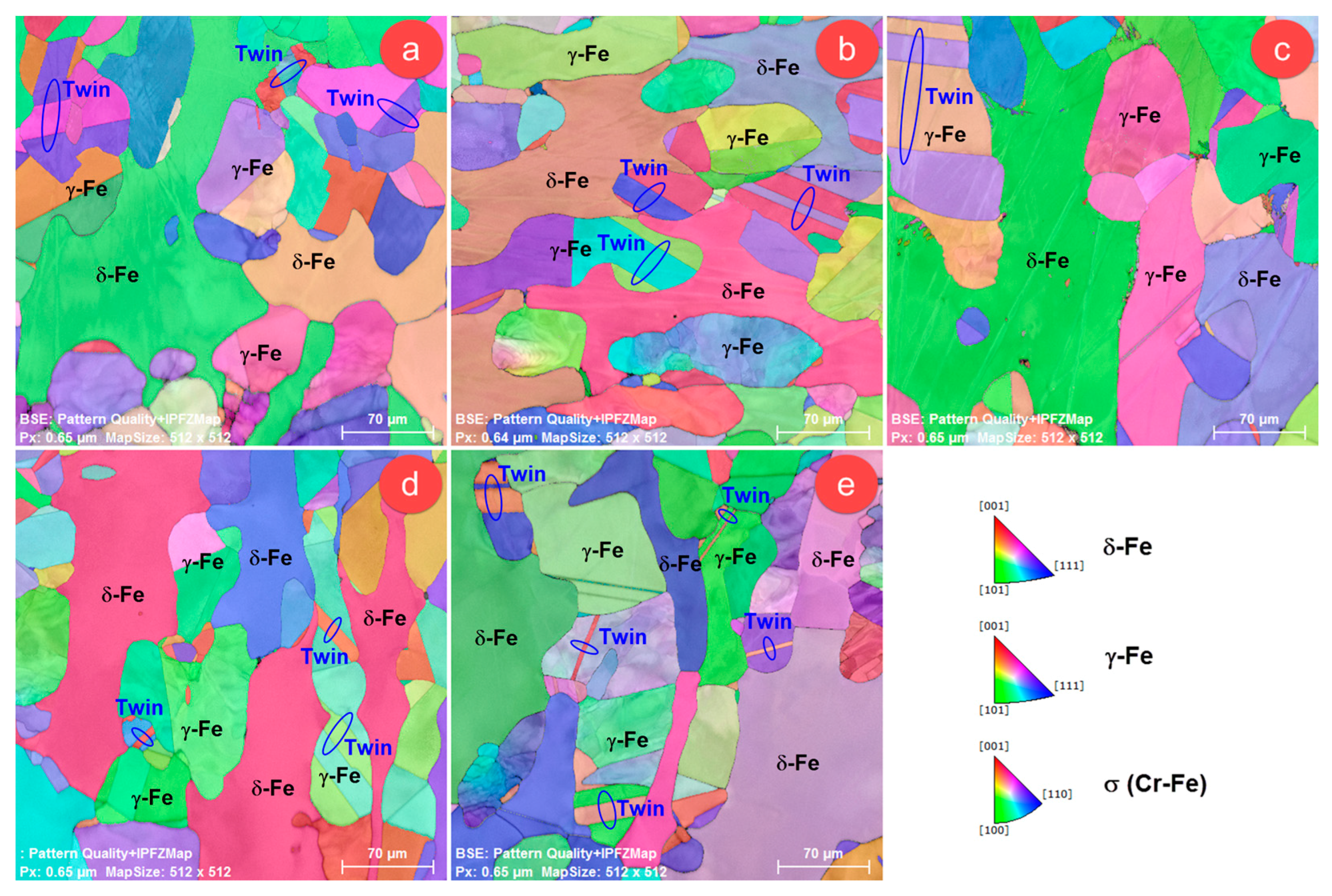
3. Results and Discussion

The microstructure of SDSS alloys usually contain a mixture of primary phases, such as δ-Fe (ferrite) and γ-Fe (austenite), and other secondary phases, such as: σ (Cr-Fe) (sigma), χ (chi), Cr2N (chromium nitride), M23C6 (carbides) and γ2-Fe (secondary austenite) [27,28,29,30,31,32].
In the case of UNS S32750/1.4410/F53 SDSS alloy thermo-mechanically processed by the procedure as described above, the microstructure consisted of δ-Fe and γ-Fe primary phases and of σ (Cr-Fe) secondary phase (Figure 2). By examining the as-forged microstructural state in both investigated areas (Figure 2a), it can be seen that σ (Cr-Fe) phase is dispersed at grain boundaries of primary phases (δ-Fe and γ-Fe). Although δ-Fe and γ-Fe primary phases are distinguishable also by SEM-BSE [14], due to their close chemical composition, it is easier to distinguish and characterize them using the SEM-EBSD analysis.
The fraction of σ (Cr-Fe) phase is higher for solution temperatures of 800 °C (Figure 2b), 900 °C (Figure 2c) and 1000 °C (Figure 2d), compared with the as-forged microstructure (Figure 2a). A higher fraction of σ (Cr-Fe) phase was obtained for solution treatment temperatures of 800 °C and 900 °C. The solution treatment temperature of 1100 °C (Figure 2e) led to a microstructure consisting only of primary δ-Fe and γ-Fe phases.
Figure 3 shows the composite phase distribution maps for the following microstructural states: as-forged (Figure 3a), solution-treated at 800 °C for 0.6 ks (Figure 3b), solution-treated at 900 °C for 0.6 ks (Figure 3c), solution-treated at 1000 °C for 0.6 ks (Figure 3d) and solution-treated at 1100 °C for 0.6 ks (Figure 3e).
It can be seen that, in all cases, the microstructure consisted of δ-Fe phase as matrix phase, containing a dispersed, irregular, elongated γ-Fe phase. As observed, the σ (Cr-Fe) phase is located at δ-Fe/γ-Fe grain boundaries (Figure 3a–d). The SEM-EBSD analysis confirmed that a solution treatment temperature of 1100 °C led to a microstructure formed only of primary δ-Fe and γ-Fe phases, no σ (Cr-Fe) phase being detected.
Figure 4 shows higher-magnification SEM-EBSD images for as-forged, solution-treated at 800 °C, 900 °C and 1000 °C investigated microstructural states. As observed, in all cases the microstructure consisted of a mixture of δ-Fe, γ-Fe and σ (Cr-Fe) grains. The as-forged microstructural state (Figure 4a) showed high-size δ-Fe and γ-Fe grains and small-size σ (Cr-Fe) grains, the average grain-size of σ (Cr-Fe) phase being situated close to 3 μm. The σ (Cr-Fe) phase is formed during the slow cooling of forged product, due to chromium diffusion towards grain boundaries. For instance, in the case of a stabilized AISI 347 austenitic stainless steel under heat treatments, it was shown that σ (Cr-Fe) phase precipitation is a very slow process and usually small grains and very low proportions are obtained during slow cooling [34]. It was also reported that, for a type 316FR austenitic stainless steel weld metal under isothermal ageing treatments, σ-phase usually precipitates around grain inclusions, incoherent grain boundaries and δ-Fe/ γ-Fe grain boundaries region [35].
The solution treatment temperature of 800 °C (Figure 4b) led to an increased grain-size of σ (Cr-Fe) phase and to a higher fraction of σ (Cr-Fe) phase, with an average grain-size close to 8–9 μm. By increasing the solution treatment temperature at 900 °C (Figure 4c), the fraction of σ (Cr-Fe) phase raised, but the average grain-size of σ (Cr-Fe) phase diminished. This could be explained considering the fact that locally, during heating at temperatures higher than 850 °C, δ-Fe partially transforms to γ-Fe and σ (Cr-Fe) phases, new σ precipitate nuclei appearing at grain boundaries [36,37] and starting to grow. On the other hand, it was also reported that σ phase becomes unstable above 860 °C, the σ grains starting to dissolve when the temperature is increased above this value, but they do not disappear completely until 985 °C [36,37]. A solution treatment temperature of 1000 °C led to decreasing of both weight fraction and average grain-size of σ (Cr-Fe) phase, the average grain-size being situated close to 4 μm. This behaviour can be explained by the influence of temperature on precipitation and dissolution mechanisms of σ (Cr-Fe) phase. In this regard, in situ observations were made on σ phase formation and dissolution in a 2205 duplex stainless steel using synchrotron X-Ray diffraction [36,37] and it was reported that σ phase precipitates rapidly in the initial stages of heating, dissolves as the temperature increases and is reformed on cooling, the dissolution temperature of σ being determined as 985 ± 2.8 °C at a heating rate of 0.25 °C/s.
The data concerning computed fractions of phases (statistical determination of weight fraction for each phase detected and its standard deviation) are presented in Table 1, showing that the δ-Fe phase fraction grew from 45.13 ± 3.66% to 48.89 ± 3.56% by raising the solution treatment temperature, while γ-Fe phase fraction decreased from 54.81 ± 3.01% to 51.11 ± 3.29% by increasing the solution treatment temperature. The σ (Cr-Fe) phase fraction increased from 0.06 ± 0.03% up to 0.73 ± 0.05% by raising the solution treatment temperature to 900 °C. Further increase of temperature led to a decreasing fraction of σ (Cr-Fe) phase, no σ (Cr-Fe) phase being detected at 1100 °C.
Figure 5 shows the Inverse Pole Figure images of γ-Fe, δ-Fe and σ (Cr-Fe) phases in respect to z sample axis (IPFZ), for all investigated microstructural states: as-forged (Figure 5a) and solution-treated for 0.6 ks at 800 °C (Figure 5b), 900 °C (Figure 5c), 1000 °C (Figure 5d) and 1100 °C (Figure 5e). It can be seen that, in all cases, the microstructure consisted of large δ-Fe phase grains, acting as a matrix, and elongated, dispersed γ-Fe phase grains.
Regardless of microstructural state, γ-Fe grains contained extended twinned areas, larger twins being detected in the as-forged state compared to solution-treated states (Figure 5a–e). This can be explained considering the fact that all observed twins are actually annealing twins, who were allowed to expand in the as-forged state, the material being slowly cooled up to the ambient temperature, while in the solution-treated states, the samples were water-quenched after a brief holding time (10 min) at the elevated treatment temperatures, restricting this way the expansion of annealing twins formed in the γ-Fe grains.
In order to identify the twinning system of γ-Fe phase twins, the following microstructural states were considered: as-forged (Figure 6), solution-treated at 800 °C for 0.6 ks and solution-treated at 1100 °C for 0.6 ks.
Analysing the case of selected twin in as-forged microstructural state (Figure 6a), the twin misorientation profile (Figure 6b) revealed that the misorientation between twinned and un-twinned grain regions was about 60°. In cubic systems, according to Coincident Site Lattice (CSL) theory, Σ3 boundaries are characterized by a misorientation of 60° [33,34]. Also, it was demonstrated that in the case of face-centred cubic systems, the {111}<112> twinning system is characterized by coherent Σ3 twin boundaries, the twin rotation angle being close to 60° [38,39]. In order to confirm the {111}<112> twinning system, the pole figures of <111> and <112> crystallographic directions were plotted (Figure 6c), being observed a single <111> common axis for twinned and un-twinned region and three <112> common axes, corresponding to twinned and un-twinned grain region. All observations confirmed that the observed twin belongs to {111}<112> twinning system.
Similar observations have also been made in the case of selected twins in microstructural states obtained after solution treatments for 0.6 ks at 800 °C and 1100 °C. The misorientation profile of selected twins showed a misorientation of 60° between twinned and un-twinned grain regions, a single <111> common axis and three <112> common axes corresponding to twinned and un-twinned grain regions. The {111}<112> twins are commonly formed in FCC (face-centred cubic) crystalline materials, during annealing and recrystallization [40,41,42].
Considering the fact that in all cases the microstructure mainly consisted of a mixture of δ-Fe and γ-Fe phases, it was necessary to analyse the crystallographic orientation/misorientation between adjacent grains from these constituent phases, in order to establish the fraction of low-angle grain boundaries (LAGBs, misorientation angle smaller than 15°) and high-angle grain boundaries (HAGBs, misorientation angle larger than 15°), the LAGBs/HAGBs ratio affecting the material properties, being reported for example that a high concentration of LAGBs is increasing the susceptibility to localised corrosion for a grade 2205 duplex stainless steel [43,44]. The acquired EBSD images were processed using the advanced features of the microscope software (Bruker ESPRIT 1.9, Bruker Corporation, Billerica, MA, USA), so that all grain boundaries available in the EBSD images were considered in this analysis. Figure 7 shows the evolution of misorientation between adjacent γ-Fe/γ-Fe grains (Figure 7a), δ-Fe/δ-Fe grains (Figure 7b) and γ-Fe/δ-Fe grains (Figure 7c). The misorientation analysis considered a misorientation distribution consisting of 10 class-sizes, with the following average misorientation class-size: 3.25°, 9.75°, 16.25°, 22.75°, 29.25°, 35.75°, 42.25°, 48.75°, 52.25° and 61.75°.
The misorientation analysis between neighbouring γ-Fe grains (Figure 7a) showed for the as-forged microstructural state a small fraction of γ-Fe grains (12–13%), with low-angle grain boundaries, the misorientation angle being less than 10°. In the case of solution-treated states, it can be seen a 50% reduction of γ-Fe phase fraction, showing low-angle grain boundaries (5–6%). For all solution treatment variants, the misorientation analysis of γ-Fe grains showed high-angle grain boundaries, characterized by a misorientation larger than 15°. Also, it can be observed that a higher fraction of γ-Fe grains (40–50%) showed a misorientation angle between 30–50°. In the as-forged microstructure, the misorientation analysis of adjacent δ-Fe grains (Figure 7b) revealed that low-angle grain boundaries are mainly formed (above 80%). The solution treatment temperature significantly influenced the fraction of low-angle grain boundaries, so that a solution treatment at 800 °C led to the formation of 28–30% δ-Fe grains with low-angle grain boundaries, while a solution treatment at 1000 °C led to the formation of 52–55% δ-Fe grains with low-angle grain boundaries. The misorientation analysis of neighbouring γ-Fe/δ-Fe grains (Figure 7c) showed that high-angle grain boundaries are mainly formed, the fraction of boundaries characterized by misorientations between 30–55° being situated close to 60–80% in all investigated cases.
The microhardness of γ-Fe and δ-Fe phases was evaluated by using an indentation force of 10 gf (HV0.01), the minimum force that can be set for the testing equipment. Figure 8 shows some generic microhardness indentation images (HV0.01) on γ-Fe phase (Figure 8a) and δ-Fe phase (Figure 8b).
The results regarding the average microhardness of both phases, calculated for all investigated microstructural states, are given in Table 2. It can be seen that, for all microstructural states, an average microhardness between 221.3 HV0.01 and 236.2 HV0.01 was obtained for γ-Fe phase, while an average microhardness between 274.1 HV0.01 and 281.4 HV0.01 was obtained for δ-Fe phase. Also, it can be observed that the solution treatment improves the microhardness of δ-Fe phase, but increasing the solution treatment temperature leads to a decrease of the average microhardness for δ-Fe, with a minimum peak at 1000 °C, the solution treatment performed at 1100 °C causing further increase in the microhardness of δ-Fe. The average microhardness of γ-Fe phase, on the other hand, records a drop as a result of solution annealing treatment, but increasing the solution treatment temperature leads to an improvement in the average microhardness for γ-Fe phase, the treatment performed at 1100 °C resulting in a microhardness value even higher than the one obtained for the initial as-forged state. This behaviour can be explained if the precipitation and dissolution phenomena of σ (Cr-Fe) phase, observed for the investigated SDSS alloy, are considered; these leading to a different partitioning of Cr between δ-Fe and γ-Fe and consequently to a change in the chemical composition of the two phases and thus, to a variation of the mechanical characteristics measured for δ-Fe and γ-Fe phases.
In order to determine the global microstructure microhardness, an indentation force of 100 gf (HV0.1) was used. Figure 9 shows the global microhardness evolution for all microstructural states. It can be seen that the minimum microhardness, close to 236 ± 5.9 HV0.1, was obtained in the case of the as-forged microstructural state, while the maximum microhardness, close to 258 ± 7.9 HV0.1, was obtained in the microstructural state corresponding to the solution treatment at 800 °C for 0.6 ks. The increasing of solution annealing temperature caused a drop in the global microhardness, so the minimum microhardness, close to 248 ± 4.6 HV0.1, was obtained in the case of solution treatment performed at 1000 °C. It was observed that the solution treatment performed at 1100 °C leads to a small increase in global microhardness in comparison with the solution treatment performed at 1000 °C, from 248 ± 4.6 HV0.1 to 250 ± 3.7 HV0.1, but this increase is smaller than the standard deviation of the measurement.
In order to explain this behaviour, the following mechanism should be considered. Firstly, the phase fractions influence through the mixing law should be taken into account, this law stating that a higher fraction of a certain phase implies a higher influence of the respective phase on the overall properties. It is known that in SDSS alloys, the highest microhardness is exhibited by σ (Cr-Fe) phase, followed by δ-Fe and γ-Fe phases [45]. According to the experimental results obtained in this study, increasing the content of σ (Cr-Fe) and δ-Fe phases led to a higher global microhardness. Furthermore, considering also the solution treatment temperature influence on constituent phases, it was shown that during heating at temperatures below 1000 °C [25,26,27,28,29], secondary phases, such as: σ (sigma), χ (chi) and Cr2N are formed [30,31,32,33], being known that these phases exhibit a higher microhardness in comparison with δ-Fe and γ-Fe phases.

4. Conclusions

The microstructural changes that occurred in an industrially forged F53 Super Duplex Stainless Steel (SDSS) alloy, during solution treating at different treatment temperatures, were studied in order to show how component phases are influenced. The obtained results can be summarized as follows:
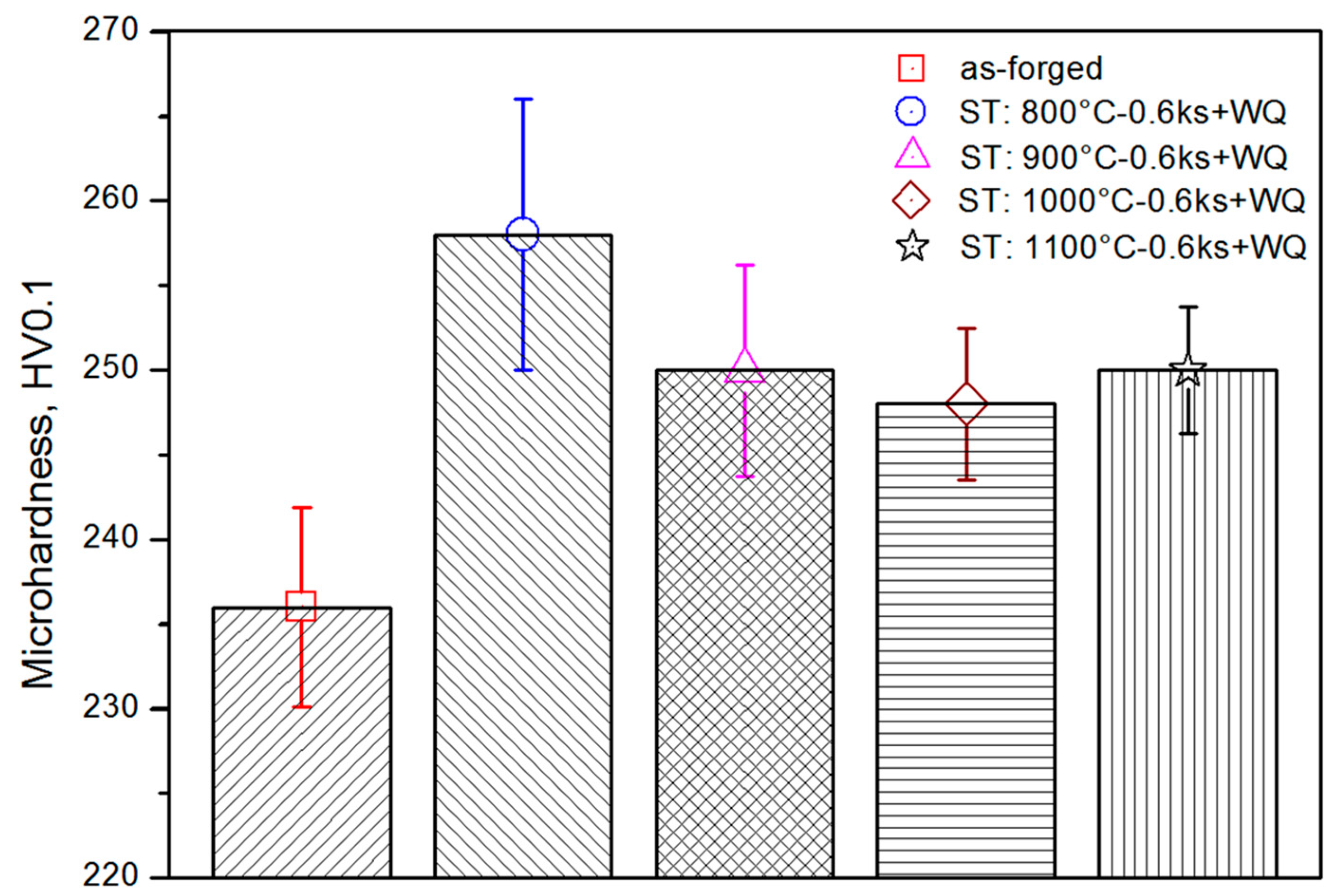
  • the main positive effect of solution treatment is represented by the possibility to control the σ phase fraction, a solution treatment temperature above 1100 °C assures obtaining microstructures with no σ phase;
  • a maximum σ phase fraction, close to 0.73 ± 0.05%, is obtained for a solution treatment temperature of 900 °C;
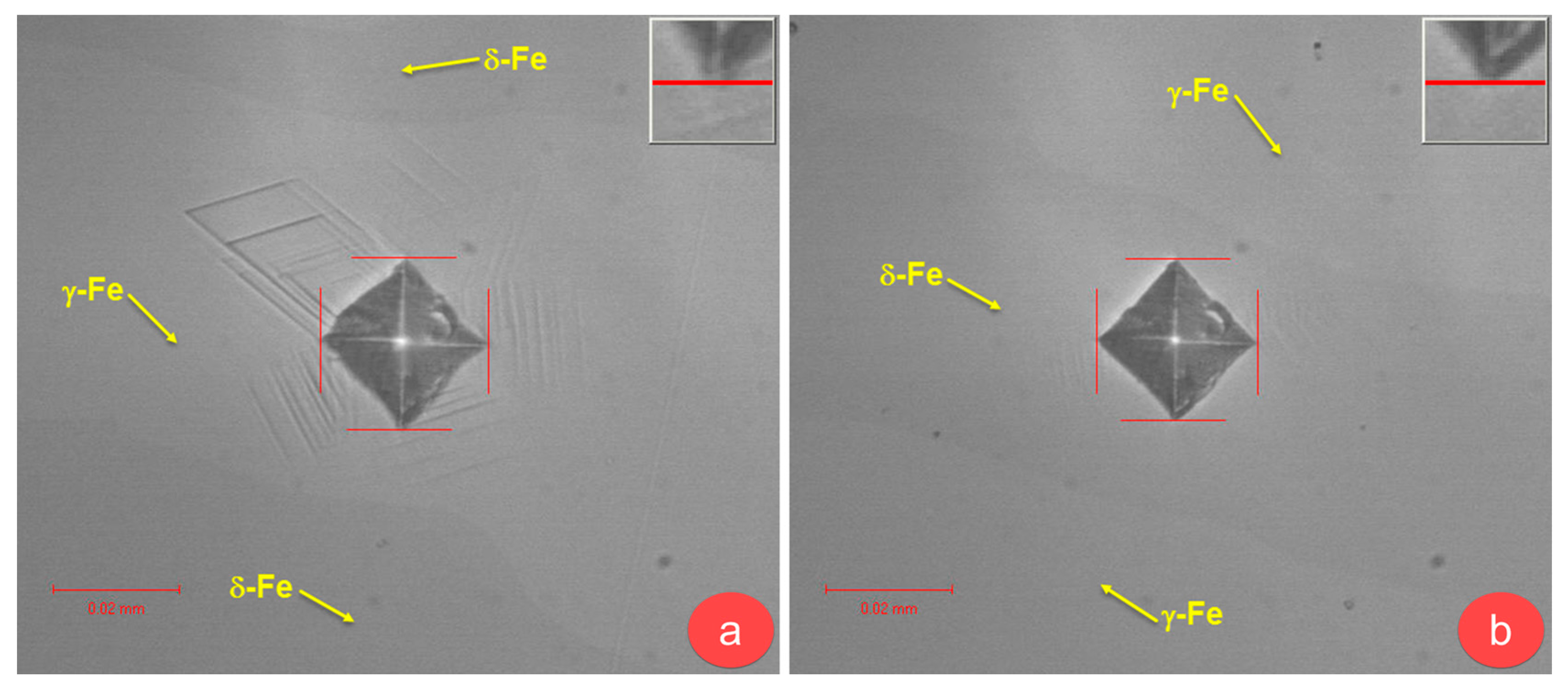
  • increasing the solution treatment temperature, from 800 °C to 1100 °C, leads to increasing of δ-Fe phase fraction, from 45.13 ± 3.66% to 48.89 ± 3.56%, while the γ-Fe phase fraction is decreased, from 54.81 ± 3.01% to 51.11 ± 3.29%;
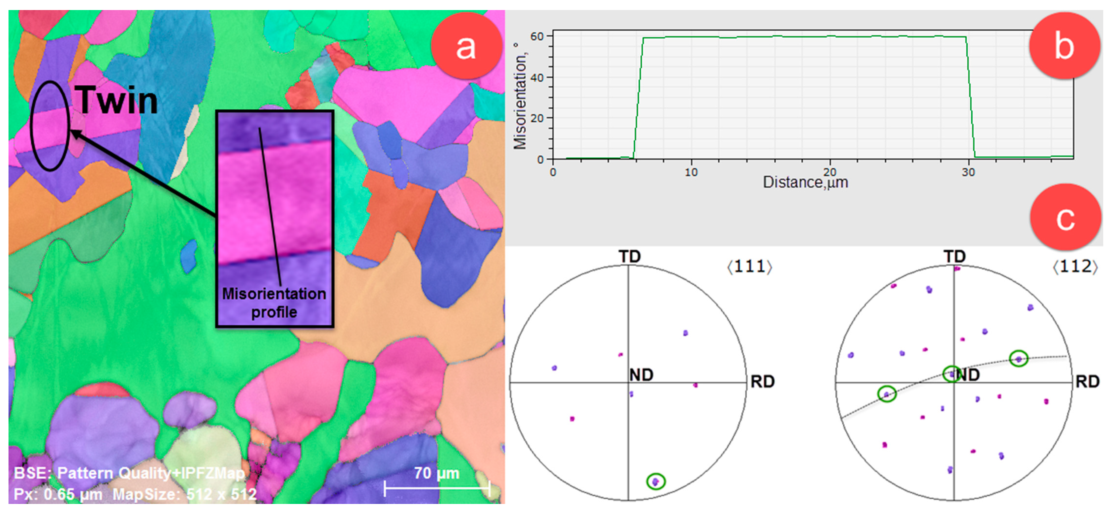
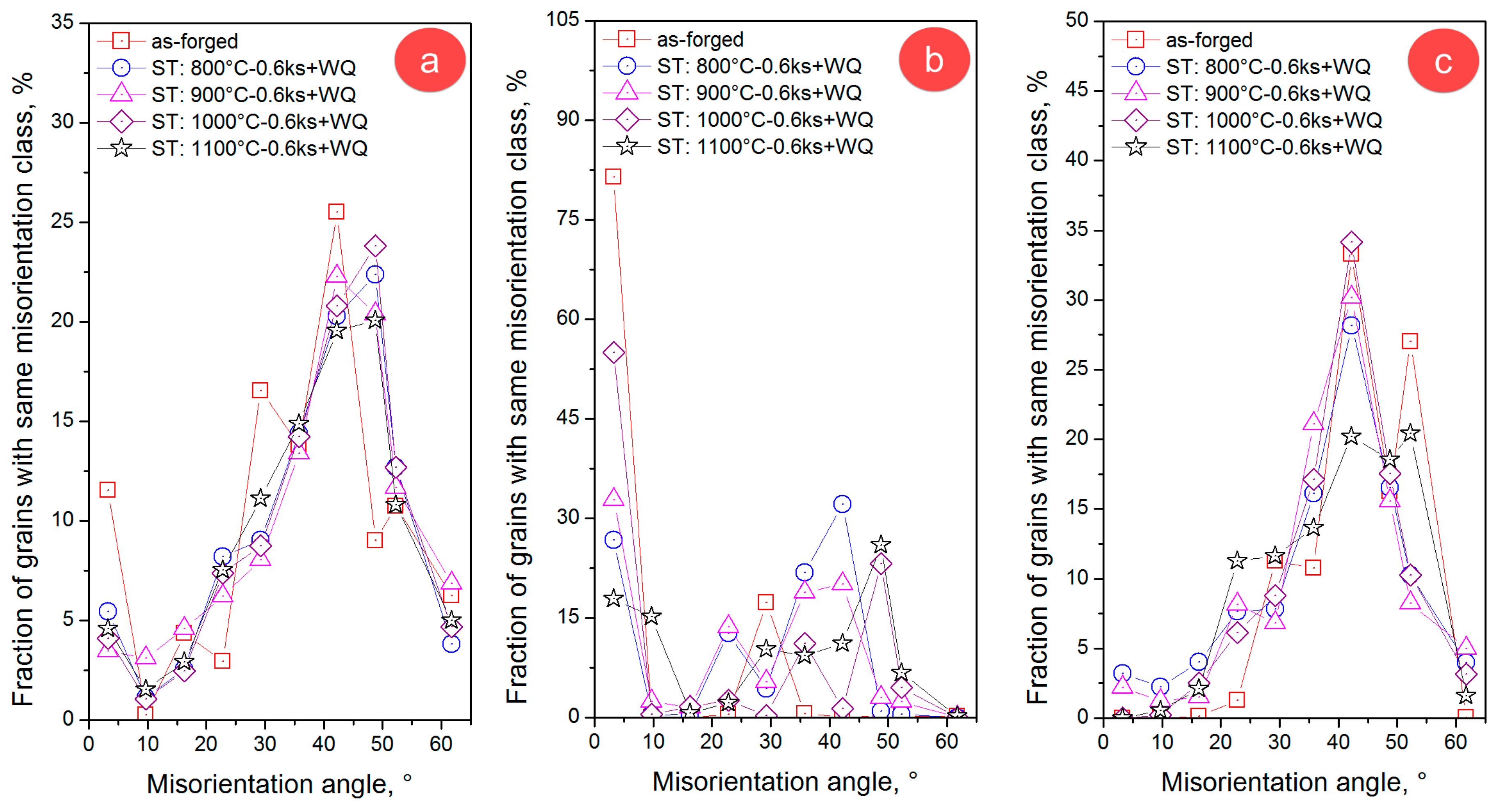
  • in all investigated microstructural states, the majority of γ-Fe/γ-Fe grain boundaries are high-angle grain boundaries, δ-Fe/δ-Fe grain boundaries are showing a mixture of low-angle grain boundaries and high-angle grain boundaries, while δ-Fe/γ-Fe grain boundaries are high-angle grain boundaries;
  • in all investigated microstructural states, the γ-Fe phase shows the presence of twins, induced during slow-cooling and solution treating, twins belonging to {111}<112> twinning system.
Further optimization of the solution treating processing route, in order to achieve microstructures consisting only in δ-Fe and γ-Fe phases, in 50–50% fractions, is currently being undertaken by the present authors.

Acknowledgments

This work was supported by a grant of the Romanian National Authority for Scientific Research, CCCDI—UEFISCDI, Project PN-III-P2-2.1-BG-2016-0367, contract No. 104 BG/2016.

Author Contributions

Vasile Dănuț Cojocaru, Nicolae Șerban and Mariana Lucia Angelescu conceived and designed the experiments; Vasile Dănuț Cojocaru, Nicolae Șerban, Mariana Lucia Angelescu, Mihai Cosmin Cotruț and Elisabeta Mirela Cojocaru performed the experiments; Vasile Dănuț Cojocaru, Nicolae Șerban and Mariana Lucia Angelescu analyzed the data; Adrian Nicolae Vintilă contributed reagents/materials/analysis tools; Vasile Dănuț Cojocaru and Nicolae Șerban wrote the paper.

Conflicts of Interest

The authors declare no conflict of interest. The founding sponsors had no role in the design of the study; in the collection, analyses, or interpretation of data; in the writing of the manuscript, and in the decision to publish the results.

References

  1. Tan, H.; Jiang, Y.; Deng, B.; Sun, T.; Xu, J.; Li, J. Effect of annealing temperature on the pitting corrosion resistance of super duplex stainless steel UNS S32750. 2009, 60, 1049–1054. [Google Scholar] [CrossRef]
  2. Tavares, S.S.M.; Pardal, J.M.; de Souza, J.A.; Neto, J.M.; da Silva, M.R. Magnetic phase quantification of the UNS S32750 superduplex stainless steel. J. Alloy. Compd. 2006, 416, 179–182. [Google Scholar] [CrossRef]
  3. Cervo, R.; Ferro, P.; Tiziani, A. Annealing temperature effects on super duplex stainless steel UNS S32750 welded joints. I: Microstructure and partitioning of elements. J. Mater. Sci. 2010, 45, 4369–4377. [Google Scholar] [CrossRef]
  4. Cervo, R.; Ferro, P.; Tiziani, A.; Zucchi, F. Annealing temperature effects on super duplex stainless steel UNS S32750 welded joints. II: Pitting corrosion resistance evaluation. J. Mater. Sci. 2010, 45, 4378–4389. [Google Scholar] [CrossRef]
  5. Bastos, I.N.; Tavares, S.S.M.; Dalard, F.; Nogueira, R.P. Effect of microstructure on corrosion behavior of superduplex stainless steel at critical environment conditions. Scr. Mater. 2007, 57, 913–916. [Google Scholar] [CrossRef]
  6. Yousefieh, M.; Shamanian, M.; Saatchi, A. Optimization of the pulsed current gas tungsten arc welding (PCGTAW) parameters for corrosion resistance of super duplex stainless steel (UNS S32760) welds using the Taguchi method. J. Alloy. Compd. 2011, 509, 782–788. [Google Scholar] [CrossRef]
  7. Tavares, S.S.M.; Silva, V.G.; Pardal, J.M.; Corte, J.S. Investigation of stress corrosion cracks in a UNS S32750 superduplex stainless steel. Eng. Fail. Anal. 2013, 35, 88–94. [Google Scholar] [CrossRef]
  8. Udayakumar, T.; Raja, K.; Abhijit, A.T.; Sathiya, P. Experimental investigation on mechanical and metallurgical properties of super duplex stainless steel joints using friction welding process. J. Manuf. Process. 2013, 15, 558–571. [Google Scholar] [CrossRef]
  9. Nilsson, J.O. Super duplex stainless steels. J. Mater. Sci. Technol. 1992, 8, 685–700. [Google Scholar] [CrossRef]
  10. Tehovnik, F.; Arzensek, B.; Arh, B.; Skobir, D.; Pirnar, B.; Zuzek, B. Microstructure evolution in SAF 2507 super duplex stainless steel. Mater. Technol. 2011, 45, 339–345. [Google Scholar]
  11. Wang, X.; Chen, W. Influence of cerium on hot workability of 00Cr25Ni7Mo4N super duplex stainless steel. J. Rare Earths 2010, 28, 295–300. [Google Scholar] [CrossRef]
  12. Lee, K.M.; Cho, H.S.; Choi, D.C. Effect of isothermal treatment of SAF 2205 duplex stainless steel on migration of δ/γ interface boundary and growth of austenite. J. Alloy. Compd. 1999, 285, 156–161. [Google Scholar] [CrossRef]
  13. Maetz, J.Y.; Cazottes, S.; Verdu, C.; Kleber, X. Precipitation and Phase Transformations in 2101 Lean Duplex Stainless Steel during Isothermal Aging. Metall. Mater. Trans. A 2016, 47, 239–253. [Google Scholar] [CrossRef]
  14. Ferro, P. A dissolution kinetics model and its application to duplex stainless steels. Acta Mater. 2013, 61, 3141–3147. [Google Scholar] [CrossRef]
  15. Martins, M.; Casteletti, L.C. Sigma phase morphologies in cast and aged super duplex stainless steel. Mater. Charact. 2009, 60, 792–795. [Google Scholar] [CrossRef]
  16. Martins, M.; Casteletti, L.C. Microstructural characteristics and corrosion behavior of a super duplex stainless steel casting. Mater. Charact. 2009, 60, 150–155. [Google Scholar] [CrossRef]
  17. Pardal, J.M.; Tavares, S.S.M.; Fonseca, M.C.; de Souza, J.A.; Côrte, R.R.A.; de Abreu, H.F.G. Influence of the grain size on deleterious phase precipitation in superduplex stainless steel UNS S32750. Mater. Charact. 2009, 60, 165–172. [Google Scholar] [CrossRef]
  18. Ezuber, H.M.; El-Houd, A.; El-Shawesh, F. Effects of sigma phase precipitation on seawater pitting of duplex stainless steel. Desalination 2007, 207, 268–275. [Google Scholar] [CrossRef]
  19. García-Rentería, M.A.; López-Morelos, V.H.; García-Hernández, R.; Dzib-Pérez, L.; García-Ochoa, E.M.; González-Sánchez, J. Improvement of localised corrosion resistance of AISI 2205 Duplex Stainless Steel joints made by gas metal arc welding under electromagnetic interaction of low intensity. Appl. Surf. Sci. 2014, 321, 252–260. [Google Scholar] [CrossRef]
  20. Zhang, W.; Zou, D.N.; Fan, G.W.; Li, J. Influence of Aging Time on Sigma Phase Precipitation in SAF2507 Super-Duplex Stainless Steel. Mater. Sci. Forum 2009, 620–622, 355–358. [Google Scholar] [CrossRef]
  21. Armas, A.F.; Herenu, S.; Alvarez-Armas, I.; Degallaix, S.; Condo, A.; Lovey, F. The influence of temperature on the cyclic behavior of aged and unaged super duplex stainless steels. Mater. Sci. Eng. A 2008, 491, 434–439. [Google Scholar] [CrossRef]
  22. Argandona, G.; Biezma, M.V.; Berrueta, J.M.; Berlanga, C.; Ruiz, A. Detection of Secondary Phases in UNS S32760 Superduplex Stainless Steel by Destructive and Non-destructive Techniques. J. Mater. Eng. Perform. 2016, 25, 5269–5279. [Google Scholar] [CrossRef]
  23. Guo, Y.; Hu, J.; Li, J.; Jiang, L.; Liu, T.; Wu, Y. Effect of Annealing Temperature on the Mechanical and Corrosion Behavior of a Newly Developed Novel Lean Duplex Stainless Steel. Materials 2014, 7, 6604–6619. [Google Scholar] [CrossRef]
  24. Ma, M.; Ding, H.; Tang, Z.; Zhao, J.; Jiang, Z.; Fan, G. Effects of Temperature and Strain Rate on Flow Behavior and Microstructural Evolution of Super Duplex Stainless Steel under Hot Deformation. J. Iron Steel Res. Int. 2016, 23, 244–252. [Google Scholar] [CrossRef]
  25. Deng, B.; Jiang, Y.M.; Gao, J.; Li, J. Effect of annealing treatment on microstructure evolution and the associated corrosion behavior of a super-duplex stainless steel. J. Alloy. Compd. 2010, 493, 461–464. [Google Scholar] [CrossRef]
  26. Weber, L.; Uggowitzer, P.J. Partitioning of chromium and molybdenum in super duplex stainless steels with respect to nitrogen and nickel content. Mater. Sci. Eng. A 1998, 242, 222–229. [Google Scholar] [CrossRef]
  27. Southwick, P.D.; Honeycombe, R.W.K. Precipitation of M23C6 at austenite/ferrite interfaces in duplex stainless steel. Met. Sci. 1982, 16, 475–482. [Google Scholar] [CrossRef]
  28. Unnikrishnan, K.; Mallik, A.K. Aging behaviour of a duplex stainless steel. Mater. Sci. Eng. A 1987, 95, 259–265. [Google Scholar] [CrossRef]
  29. Duprez, L.; Cooman, B.D.; Akdut, N. Microstructure evolution during isothermal annealing of a standard duplex stainless steel type 1.4462. Steel Res. 2000, 71, 417–422. [Google Scholar] [CrossRef]
  30. Nowacki, J.; Lukojc, A. Microstructural transformations of heat affected zones in duplex steel welded joints. Mater. Charact. 2006, 56, 436–441. [Google Scholar] [CrossRef]
  31. Maetz, J.Y.; Douillard, T.; Cazottes, S.; Verdu, C.; Kléber, X. M23C6 carbides and Cr2N nitrides in aged duplex stainless steel: A SEM, TEM and FIB tomography investigation. Micron 2016, 84, 43–53. [Google Scholar] [CrossRef] [PubMed]
  32. Pohl, M.; Storz, O.; Glogowski, T. Effect of intermetallic precipitations on the properties of duplex stainless steel. Mater. Charact. 2007, 58, 65–71. [Google Scholar] [CrossRef]
  33. Liang, X.Z.; Dodge, M.F.; Liang, W.; Dong, H.B. Precipitation of chromium nitride nano-rods on lamellar carbides along austenite-ferrite boundaries in super duplex stainless steel. Scr. Mater. 2017, 127, 45–48. [Google Scholar] [CrossRef]
  34. Fernandez Bordin, S.; Limandri, S.; Ranalli, J.M.; Castellano, G. EBSD spatial resolution for detecting sigma phase in steels. Ultramicroscopy 2016, 171, 177–185. [Google Scholar] [CrossRef] [PubMed]
  35. Chun, E.J.; Baba, H.; Terashima, K.; Nishimoto, K.; Saida, K. Prediction of σ phase precipitation in type 316FR stainless steel weld metal. Q. J. Jpn. Weld. Soc. 2013, 31, 168–172. [Google Scholar] [CrossRef]
  36. Elmer, J.W.; Palmer, T.A.; Specht, E.D. Direct Observations of Sigma Phase Formation in Duplex Stainless Steels Using In-Situ Synchrotron X-Ray Diffraction. Metall. Mater. Trans. A 2007, 38, 464–475. [Google Scholar] [CrossRef]
  37. Elmer, J.W.; Palmer, T.A.; Specht, E.D. In situ observations of sigma phase dissolution in 2205 duplex stainless steel using synchrotron X-ray diffraction. Mater. Sci. Eng. A 2007, 459, 151–155. [Google Scholar] [CrossRef]
  38. Christian, J.W.; Mahajan, S. Deformation twinning. Prog. Mater. Sci. 1995, 39, 1–157. [Google Scholar] [CrossRef]
  39. Liang, Z.Y.; Huang, M.X. Deformation twinning in small-sized face-centred cubic single crystals: Experiments and modelling. J. Mech. Phys. Solids 2015, 85, 128–142. [Google Scholar] [CrossRef]
  40. Grube, W.L.; Rouze, S.R. The Origin, Growth and Annihilation of Annealing Twins in Austenite. Can. Metall. Q. 1963, 2, 31–52. [Google Scholar] [CrossRef]
  41. Gleiter, H. The formation of annealing twins (Formation des macles de recuit/Die bildung von anaβzwillingen). Acta Metall. 1969, 17, 1421–1428. [Google Scholar] [CrossRef]
  42. Mahajan, S.; Pande, C.S.; Imam, M.A.; Rath, B.B. Formation of annealing twins in f.c.c. crystals. Acta Mater. 1997, 45, 2633–2638. [Google Scholar] [CrossRef]
  43. Örnek, C.; Engelberg, D.L. SKPFM measured Volta potential correlated with strain localisation in microstructure to understand corrosion susceptibility of cold-rolled grade 2205 duplex stainless steel. Corros. Sci. 2015, 99, 164–171. [Google Scholar] [CrossRef]
  44. Örnek, C.; Engelberg, D.L. Towards understanding the effect of deformation mode on stress corrosion cracking susceptibility of grade 2205 duplex stainless steel. Mater. Sci. Eng. A 2016, 666, 269–279. [Google Scholar] [CrossRef]
  45. Badji, R.; Bouabdallah, M.; Bacroix, B.; Kahloun, C.; Belkessa, B.; Maza, H. Phase transformation and mechanical behavior in annealed 2205 duplex stainless steel welds. Mater. Charact. 2008, 59, 447–453. [Google Scholar] [CrossRef]
Figure 1. (a) Sample reference frame FD-ND-TD (FD—forging direction, ND—normal direction, TD—transverse direction), 1—forged bar, 2—forging anvils; (b) Forged bar slice showing the location of area sampling.
Metals 07 00210 g001
Figure 2. SEM-BSE micrographs of: (a) as-forged UNS S32750/1.4410/F53 SDSS alloy; (b) solution-treated (ST) at 800 °C for 0.6 ks; (c) ST at 900 °C for 0.6 ks; (d) ST at 1000 °C for 0.6 ks; (e) ST at 1100 °C for 0.6 ks.
Metals 07 00210 g002
Figure 3. SEM-EBSD Pattern Quality (PQ) and composite phase distribution map of: (a) as-forged UNS S32750/1.4410/F53 SDSS alloy; (b) solution-treated (ST) at 800 °C for 0.6 ks; (c) ST at 900 °C for 0.6 ks; (d) ST at 1000 °C for 0.6 ks; (e) ST at 1100 °C for 0.6 ks.
Metals 07 00210 g003
Figure 4. SEM-EBSD images of composite phases map distribution for all detected phases in the case of: (a) as-forged UNS S32750/1.4410/F53 SDSS alloy; (b) solution-treated (ST) at 800 °C for 0.6 ks; (c) ST at 900 °C for 0.6 ks; (d) ST at 1000 °C for 0.6 ks.
Metals 07 00210 g004
Figure 5. Inverse Pole Figure in respect to z sample axis (IPFZ) images of both δ-Fe and γ-Fe phases for: (a) as-forged UNS S32750/1.4410/F53 SDSS alloy; (b) solution-treated (ST) at 800 °C for 0.6 ks; (c) ST at 900 °C for 0.6 ks; (d) ST at 1000 °C for 0.6 ks; (e) ST at 1100 °C for 0.6 ks.
Metals 07 00210 g005
Figure 6. (a) Inverse Pole Figure in respect to ND sample axis (IPFZ) image of γ-Fe phase in the case of hot-forged and slow-cooled structural state; (b) misorientation profile of investigated twin; (c) <111> and <112> Pole Figures (PFs) of investigated twin.
Metals 07 00210 g006
Figure 7. Evolution of fraction of grains with the same misorientation class in the case of: (a) γ-Fe/γ-Fe grains; (b) δ-Fe/δ-Fe grains; (c) γ-Fe/δ-Fe grains.
Metals 07 00210 g007
Figure 8. Microhardness indentation images on: (a) γ-Fe phase and (b) δ-Fe phase.
Metals 07 00210 g008
Figure 9. Global microhardness evolution for all investigated microstructural states.
Metals 07 00210 g009
Table 1. Computed weight fractions of observed phases for all investigated microstructural states. WQ means water-quenching.
PhaseAs-ForgedSolution-Treated
800 °C—0.6 ks + WQ900 °C—0.6 ks + WQ1000 °C—0.6 ks + WQ1100 °C—0.6 ks + WQ
δ-Fe (%)45.13 ± 3.6645.26 ± 3.6147.11 ± 3.7448.54 ± 3.7248.89 ± 3.56
γ-Fe (%)54.81 ± 3.0154.48 ± 3.9752.16 ± 3.3951.33 ± 3.4951.11 ± 3.29
σ (Cr-Fe) (%)0.06 ± 0.030.23 ± 0.050.73 ± 0.050.13 ± 0.04-
Table 2. Average microhardness values of δ-Fe and γ-Fe phases for all investigated microstructural states.
PhaseAs-ForgedSolution-Treated
800 °C—0.6 ks + WQ900 °C—0.6 ks + WQ1000 °C—0.6 ks + WQ1100 °C—0.6 ks + WQ
δ-Fe (HV0.01)274.1281.4277.6276.4278.0
γ-Fe (HV0.01)235.5221.3231.1234.9236.2

