Article

Non-Isothermal Gas-Based Direct Reduction Behavior of High Chromium Vanadium-Titanium Magnetite Pellets and the Melting Separation of Metallized Pellets

School of Metallurgy, Northeastern University, Shenyang 110819, China
*
Authors to whom correspondence should be addressed.
Metals 2017, 7(5), 153; https://doi.org/10.3390/met7050153
Submission received: 14 March 2017 / Revised: 11 April 2017 / Accepted: 20 April 2017 / Published: 26 April 2017

Abstract

:
The non-isothermal reduction behavior of high chromium vanadium-titanium magnetite (HCVTM) pellets by gas mixtures was investigated using different heating rates (4, 8, and 12 K/min) and varied gas compositions (H2/CO = 2/5, H2/CO = 1/1, and H2/CO = 5/2 volume ratios); the pellets were then used for melting separation. It was observed that the temperature corresponding to the maximum reduction ratio increased with the increasing heating rate. The HCVTM pellets reached the same final reduction ratio under a given reducing gas composition, although the heating rates were different. Under the same heating rate, the gas mixture with more H2 was conducive for obtaining a higher reduction ratio. The phase transformations during the non-isothermal reduction were ordered as follows: Fe2O3 → Fe3O4 → FeO → Fe; Fe9TiO15 + Fe2Ti3O9 → Fe2.75Ti0.25O4 → FeTiO3 → TiO2; V1.7Cr0.3O3 → V2O3 → Fe2VO4; Fe1.2Cr0.8O3 → Cr2O3 → FeCr2O4. The non-isothermal reduction kinetic model was established based on the unreacted core model with multiple reaction interfaces. The correlation coefficients were greater than 0.99, revealing that this kinetic model could properly describe the non-isothermal reduction of the HCVTM pellets by gas mixtures. Iron containing V and Cr along with the Ti-rich slag was obtained through the melting separation of the metallized HCVTM pellets. The mass fractions and recovery rates of Fe, V, and Cr in the iron were 93.87% and 99.45%, 0.91% and 98.83%, and 0.72% and 95.02%, respectively. The mass fraction and recovery rate of TiO2 in the slag were 38.12% and 95.08%, respectively.

1. Introduction

High chromium vanadium-titanium magnetite (HCVTM) is a typically complex polymetallic iron ore resource with abundant reserves in China. It is mainly deposited around the Panzhihua-Xichang (Panxi) area in the Sichuan province and has a high comprehensive utilization value due to the significant reserves of Fe, V, Ti, and Cr [1,2,3] in the ore. Currently, the main disposal method for this special iron ore is a blast furnace-converter process. However, the utilization rates of the valuable components (Fe, V, Ti, and Cr) are low, and the process results in serious environment pollution such as the use of a large quantity of solid reducing agent, the freely stacked Ti-bearing slag, and the leaching of toxic elements from the slag stock [4,5,6].
Some direct reduction processes have been attempted and adopted to utilize vanadium-titanium magnetite (VTM) or HCVTM [7,8,9]. Among these processes, one promising choice is the gas-based direct reduction process with the advantages of clean production, low carbon consumption, and a fast reaction rate [10]. Meanwhile, the Ti-bearing slag cannot be polluted by the gaseous reducing agent without ash, which is good for obtaining the Ti-bearing slag with high activity and grade leading to the smooth subsequent extraction of Ti from the slag. Several experiments have been conducted, and the mechanisms from different aspects have been studied, such as the gas-based reduction test, the reduction degree change rule, the reduction kinetics, phase transformations, and microstructure changes [11,12,13,14,15,16]. Zhang conducted fundamental research on gas-based reductions using Indonesian vanadium titanium ironsand and found that the conditions required for the pellets to achieve a metallization ratio of 90% were due to the high temperature, reduction potential, and hydrogen content [17]. In Li’s work [18], the isothermal reduction kinetics of VTM pellets under H2, CO, and H2-CO was investigated; it was shown that the pellets with small diameters and high porosities had good reducibility and that the restrictive step of the reduction process varies with the H2 content in the gas. Zhang et al. [19] reduced the VTM pellets with H2-CO-N2 gas mixtures at 1173–1473 K, and the reaction was accelerated by increasing the H2 content, while the sticking was weakened. The isothermal reduction mechanisms of the titanomagnetite with pure H2 have been investigated by Sun et al. [8]. According to their research, the interfacial reaction was the main rate-controlling step during the entire reduction. Park et al. [9,20] noted that the transformations of the Ti-bearing phases in the VTM during the CO reduction were listed as: Fe3−xTixO4 → “FeO” + Fe + (Fe3−x−δTix−δO4) → Fe + (Fe3−x−δTix−δO4) → Fe + Fe2TiO4 → Fe + FeTiO3 → Fe + TiO2 → Fe + Ti3O5 → Fe + FeTi2O3.
Based on the above findings, there were no detailed studies concerning the gas-based reduction of HCVTM pellets, especially for non-isothermal reductions. The investigations of the kinetic mechanisms primarily focused on the rough judgments about the restrictive step of the reduction and lacked a detailed model to describe the gas-based reduction of VTM or HCVTM pellets. Additionally, the transformations of the phases containing V or Cr were not discussed in the early works. On the other hand, the application of the reduced pellets has also not been reported on in the previous literature. Thus, in this work, non-isothermal reduction experiments with HCVTM pellets in H2-CO-CO2 gas mixtures were performed. Meanwhile, the reduction behavior and kinetics were studied systematically, and the metallized pellets were applied for melting separation.

2. Materials and Methods
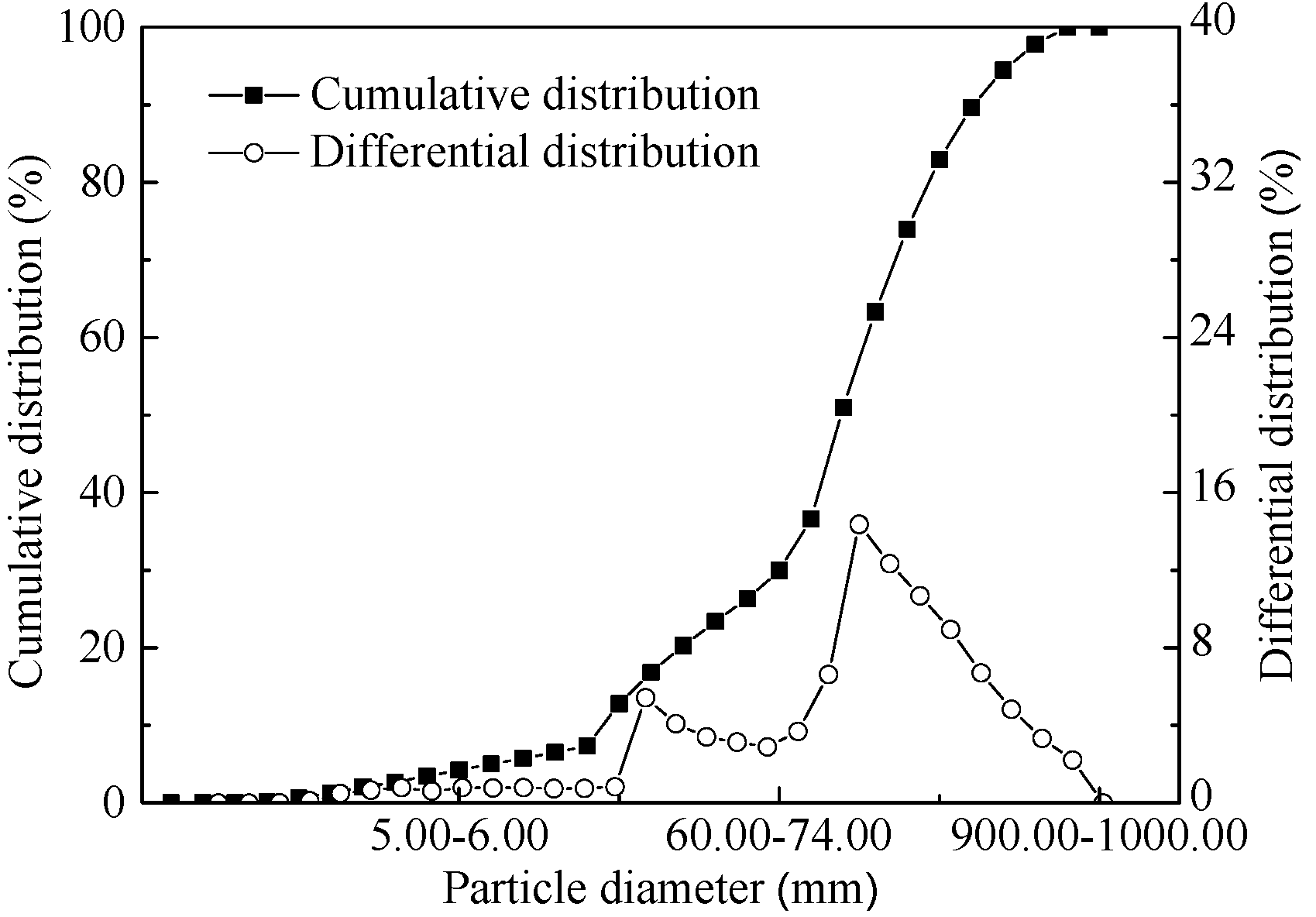
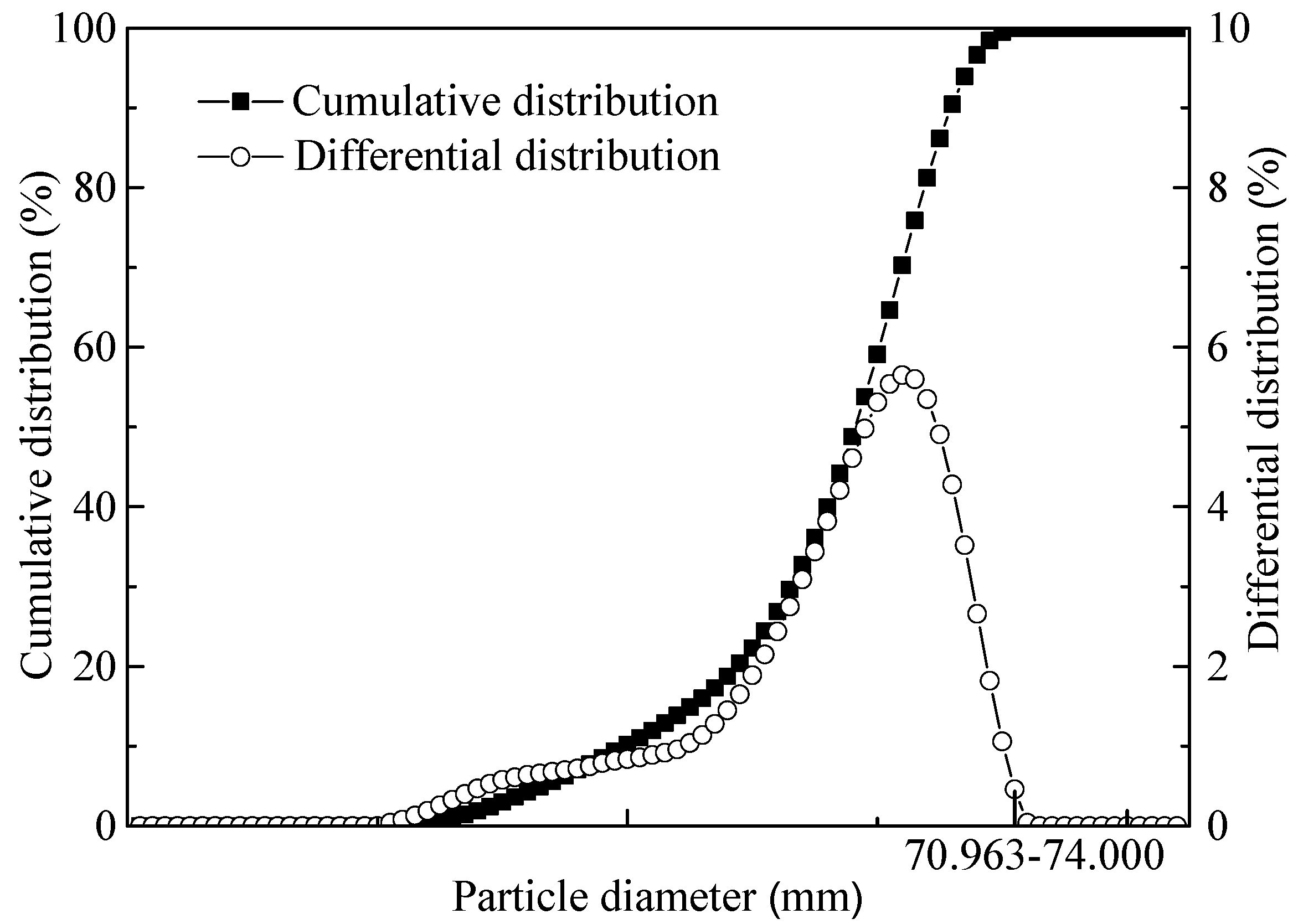
2.1. Raw Materials

The HCVTM used in the present research was supplied by Jianlong Steel in Shuangyashan, China. The chemical composition of HCVTM and bentonite are listed in Table 1. The particle size was investigated using a MASTERSIZER2000 laser particle size analyzer (Malvern Instruments, Malvern, UK), seen in Figure 1. It was clear that the volume percent of the particle size less than 0.074 mm was only 29.98%, which was not suitable for pelletizing. Therefore, the raw HCVTM was ground for the subsequent pelletizing test.

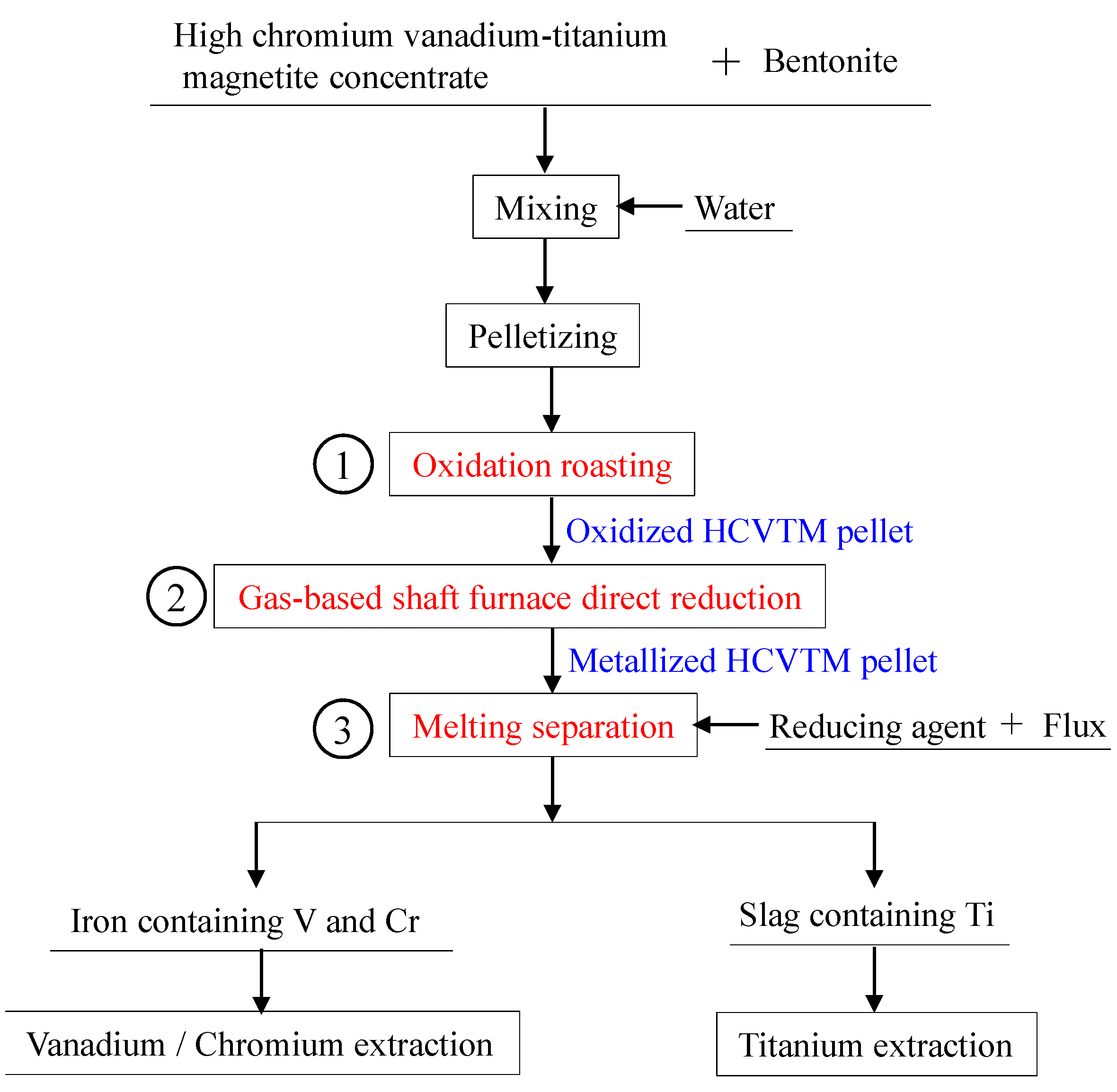
2.2. Experimental Procedure

Based on the previously discussed background, a novel process of gas-based reduction followed by melting separation for the disposal of HVCTM was proposed. The outline process chart is presented in Figure 2 and contains three key steps: (1) The HCVTM together with the bentonite was used for pelletizing, and the oxidized pellets were obtained through oxidation roasting. (2) The oxidized pellets were reduced in the gas-based shaft furnace (designed by our team). (3) The metallized pellets were used for melting separation. Finally, the slag bearing Ti and the iron containing V and Cr were obtained. In the present work, the non-isothermal gas-based direct reduction behavior of the HCVTM pellets and the melting separation of the metallized pellets were investigated.

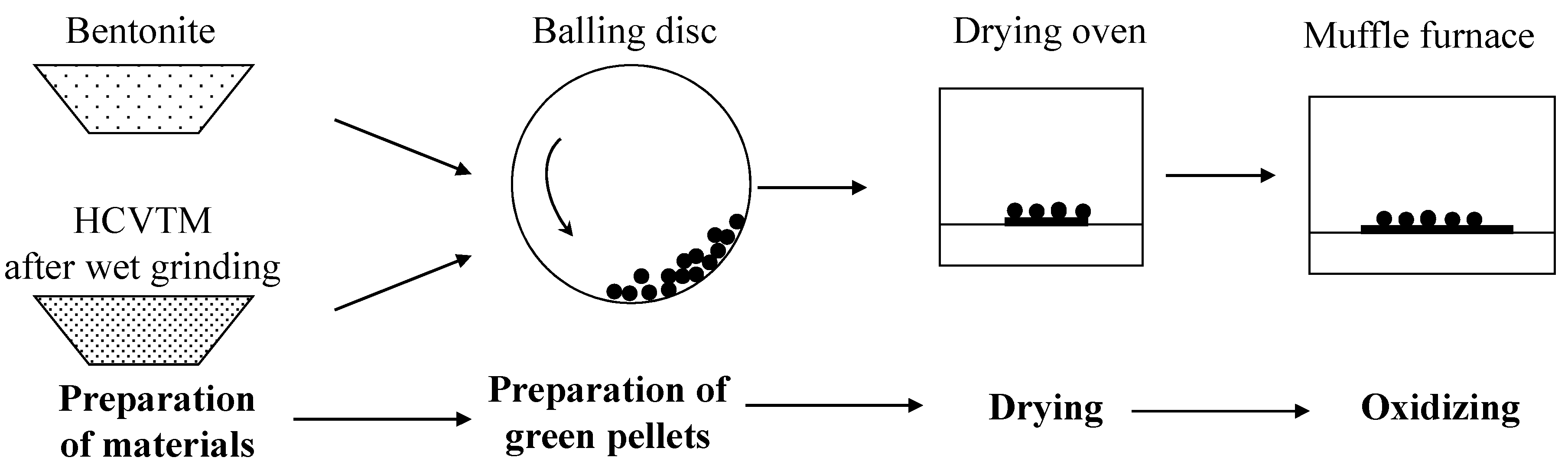
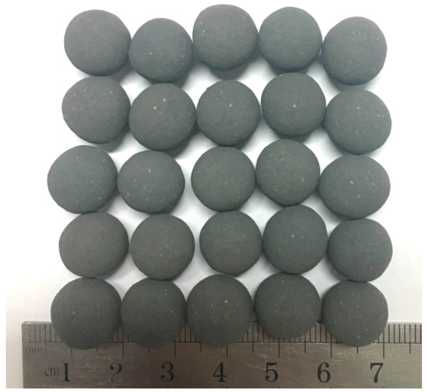
2.2.1. Pelletizing and Oxidizing of HCVTM

The pelletizing and oxidizing process of HCVTM is shown in Figure 3. Due to the big particle size of the raw HCVTM concentrate, it was handled by a laboratory wet grinder (Yunhao Mining and Metallurgy Equipment, Nanchang, China). The grinding time was controlled to approximately 15 min to assure the proper particle size, and the size distribution is reported in Figure 4. Then the ground HCVTM concentrate together with the bentonite was mixed for pelletizing. The addition of bentonite was 1.0 wt %. Green pellets were prepared using a laboratory balling disc (Danxing Machinery Equipment, Zhengzhou, China) with a diameter of 1000 mm, an edge height of 200 mm, a tilting angle of 45°, and a rotational speed of 18 rpm. Then the green pellets were dried for 5 h at 378 K in air using a drying oven (Shenguang Instrument Equipment, Shaoxing, China). Afterwards the pellets with diameters of 10–12.5 mm were screened and roasted in air using a muffle furnace (Weite Furnace, Luoyang, China). The oxidized HCVTM pellets (seen in Figure 5) were roasted for 20 min at 1573 K and were applied for non-isothermal gas-based reduction.

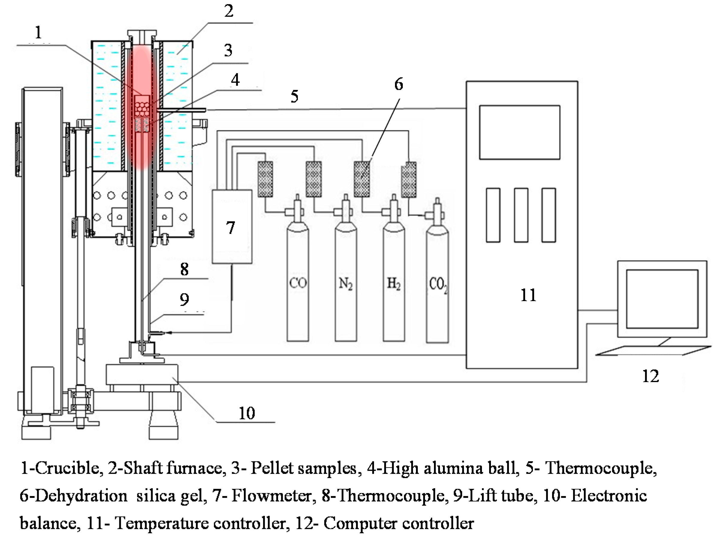
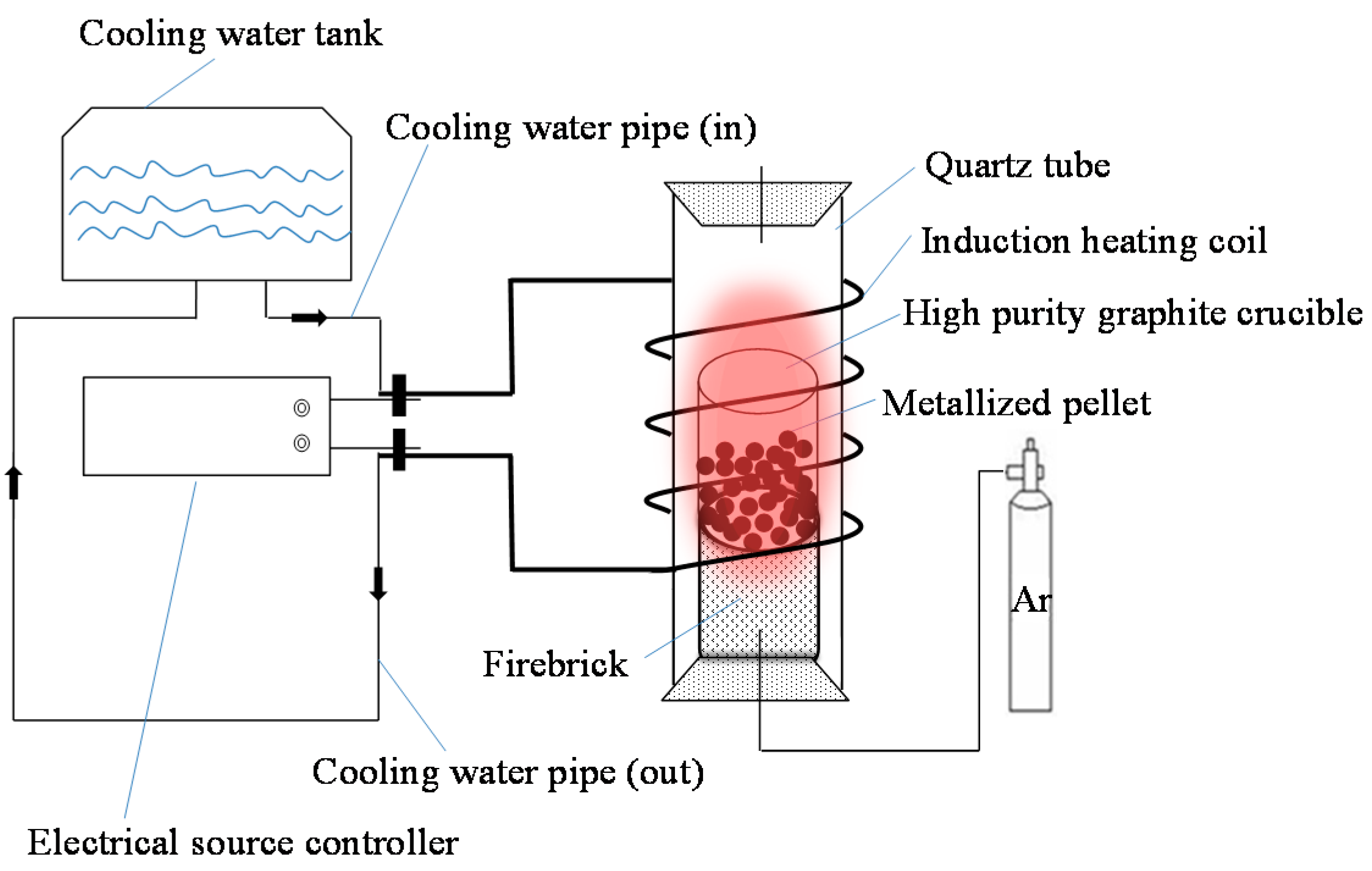
2.2.2. Gas-Based Shaft Furnace Direct Reduction of Oxidized HCVTM Pellets

The non-isothermal gas-based reduction was performed in a laboratory gas-based shaft furnace (designed by our team), as shown in Figure 6. Twenty oxidized HCVTM pellets with diameters of 12 ± 0.50 mm were placed into the crucible and moved to the effective temperature zone. Before the reduction, a N2 flow was applied with a rate of 4 L/min for several minutes to remove air from the furnace. Then, by adjusting the temperature controller, the heating rate β (K/min) was set, and the N2 flow was replaced by the H2-CO-CO2 gas mixture with the same flow rate of 4 L/min. Then, the reduction process began, and the weight loss was recorded by an electronic balance (Shengke Instrument Equipment, Shanghai, China) every 30 s. When there was no longer a change in the weight, the process was considered complete. After the reduction process, the crucible along with the pellet was removed from the furnace and was quickly cooled under an Ar flow. The reduction ratio was evaluated as the fraction of oxygen removed from the oxidized pellets. However, the oxides containing Ti, V, and Cr almost could not be reduced under the experimental temperature and atmosphere conditions. Therefore, the reduction ratio was approximately considered as the mass percentage of oxygen removed from the iron oxides and was calculated by Equation (1):
R = [ 0.11 w 1 0.43 w 2 + m 0 m t 0.43 m 0 w 2 × 100 ] × 100 %
where, w1 is the content of FeO in the oxidized HCVTM pellets, %; w2 is the content of total Fe in the oxidized HCVTM pellets, %; m0 is the initial mass of oxidized HCVTM pellets after removal of moisture, g; mt is the mass of the pellets after reducing each time t, g; and 0.11 and 0.43 are the conversion coefficients.
Three heating rates (4, 8, and 12 K/min) and gas compositions (H2/CO = 2/5, H2/CO = 1/1, and H2/CO = 5/2 volume ratios) were considered in the non-isothermal gas-based direct reduction. The volume content of the CO2 in the reducing gas was kept constant at 5%.

2.2.3. Melting Separation of the Metallized HCVTM Pellets

The melting separation proceeded in a medium frequency induction furnace (XZ-40B) (Kechuang Furnace, Zhengzhou, China), with a schematic given in Figure 7. The temperature was measured using an infrared thermometer (DT-8869h) (Huashengchang Instrument, Shenzhen, China) with a measurement range of 223–2473 K and an accuracy of 0.1 K. The metallized HCVTM pellets were crushed to below 1 mm in diameter. Then, the powder samples, reducing agent, and flux were loaded into a high purity graphite crucible (Metallurgy Graphite Material, Shenyang, China) after weighing and were mixed homogeneously. Next, the crucible was placed into the effective temperature zone and heated to a high temperature to realize the separation between the iron and the slag. The temperature and time for the melting separation was controlled at 1923 K for 40 min. After the melting separation was complete, the sample was rapidly cooled under an Ar flow.
The phase composition and microstructure of the reduced samples were investigated using XRD (X-ray Diffraction) (Siemens, Berlin, Germany) and SEM-EDS (Scanning Electron Microscopy-Energy Dispersive Spectrometer) (Zeiss, Oberkochen, Germany) analysis, respectively. The chemical composition of the iron and separated slag were analyzed by ICP-OES (Inductively Coupled Plasma Optical Emission Spectrometry) (Perkin Elmer, Waltham, MA, USA).

3. Results and Discussion

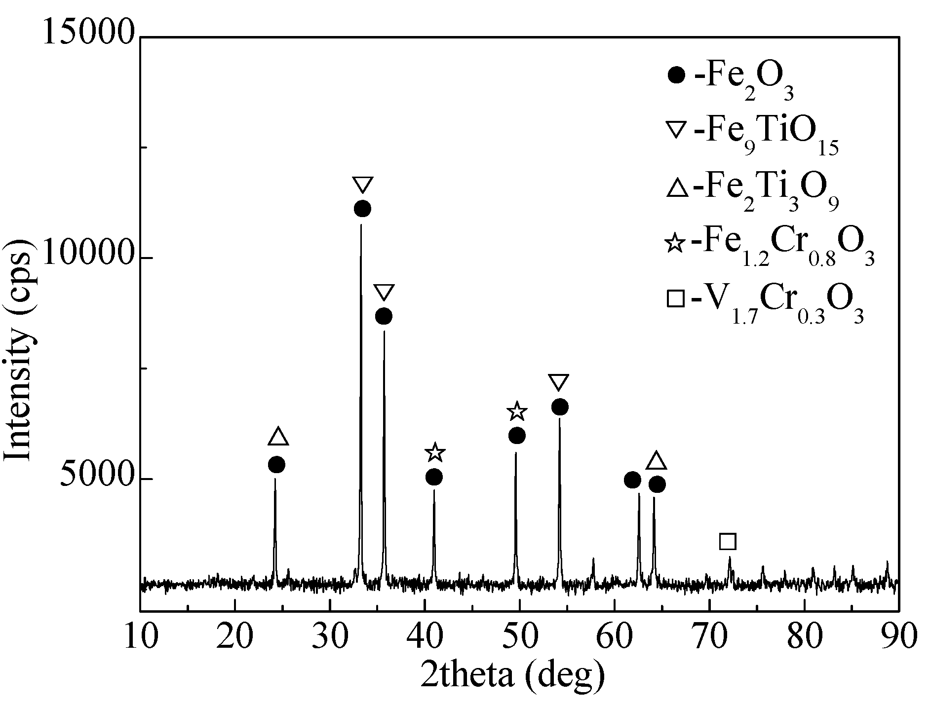
3.1. Properties of Oxidized HCVTM Pellets

The chemical compositions of the oxidized HCVTM pellets are listed in Table 2. XRD analysis was performed to determine the main phases containing Fe, Ti, V, and Cr, as shown in Figure 8. The results indicated that hematite was the main phase, and Ti was present in the forms of Fe9TiO15 (TTH) and Fe2Ti3O9. V and Cr generated their own solid solutions of V1.7Cr0.3O3 and Fe1.2Cr0.6O3. The results of SEM-EDS are given in Figure 9. It can be seen that the inner structure of the oxidized HCVTM pellets was compact, which indicated the successful and sufficient oxidation consolidation.

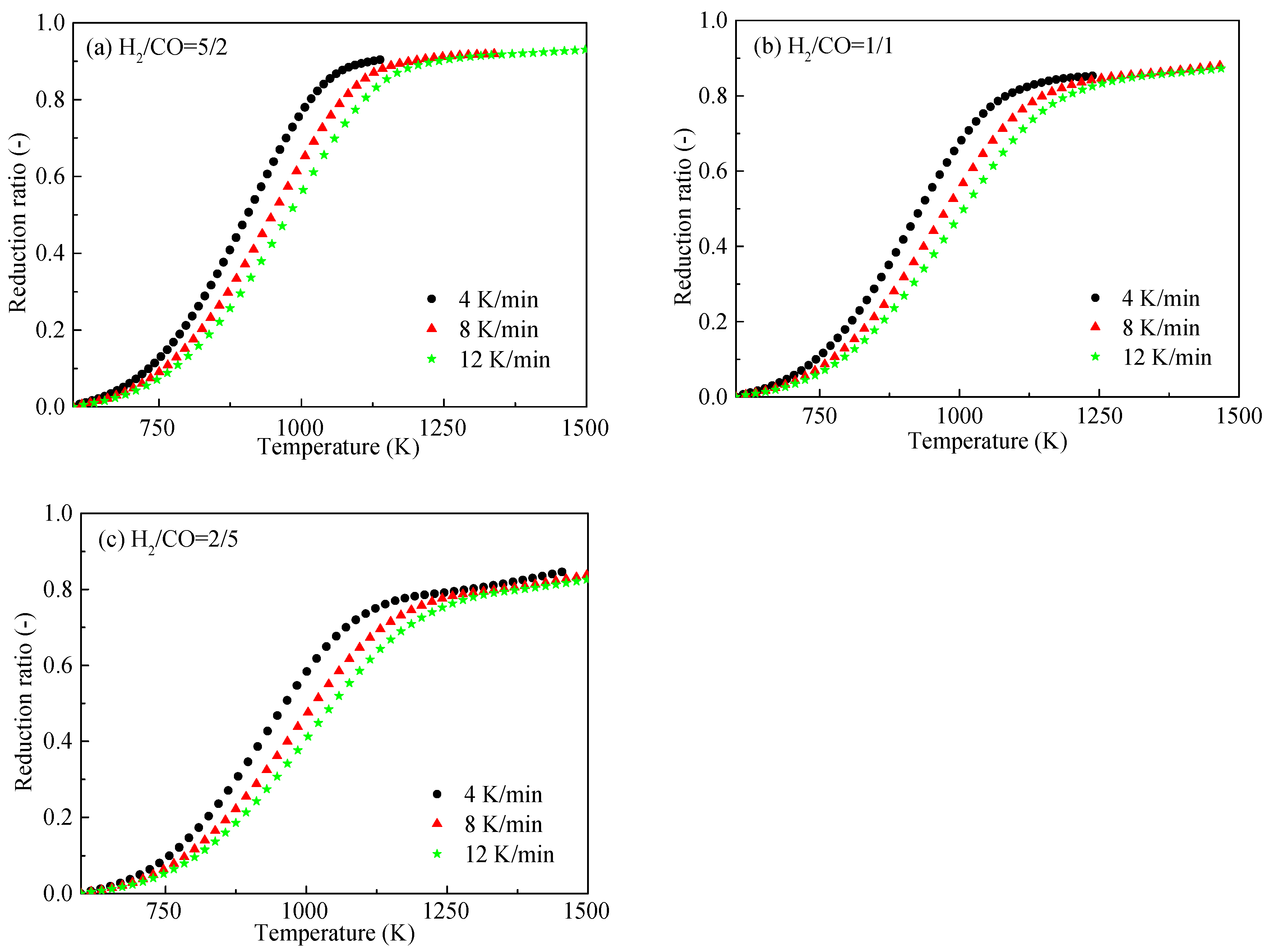
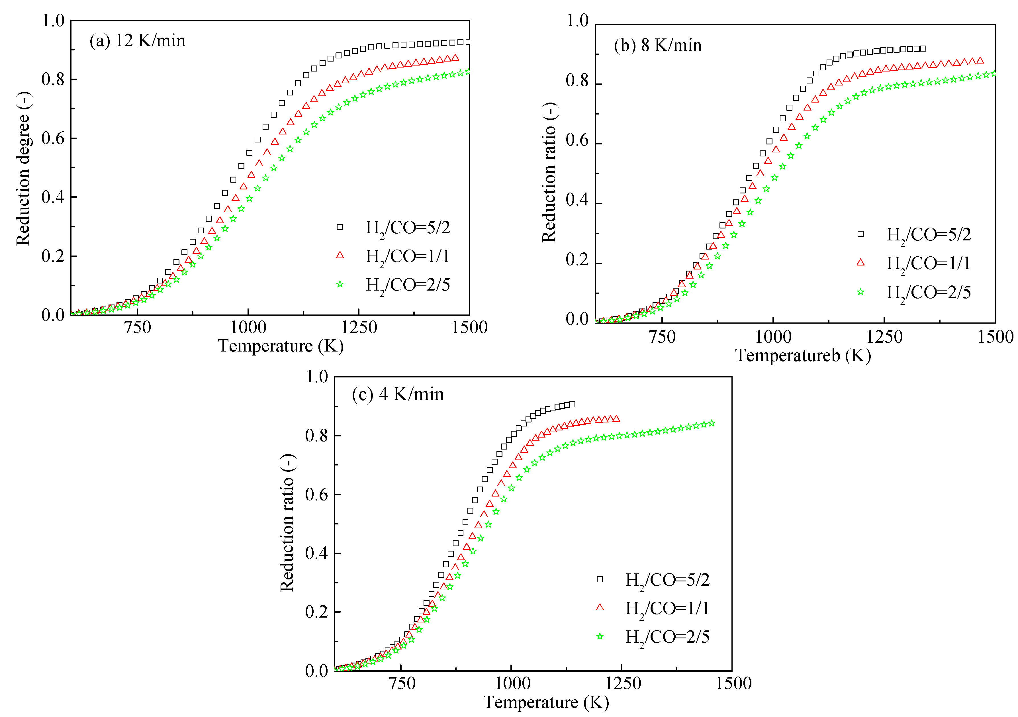
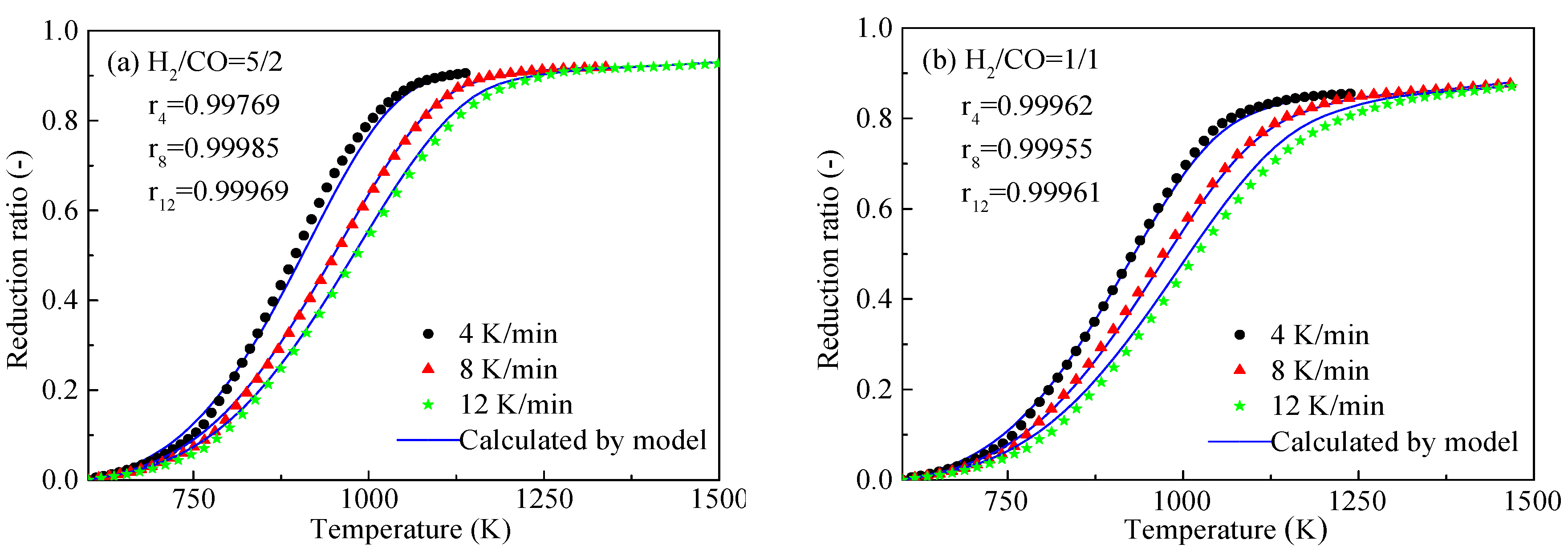
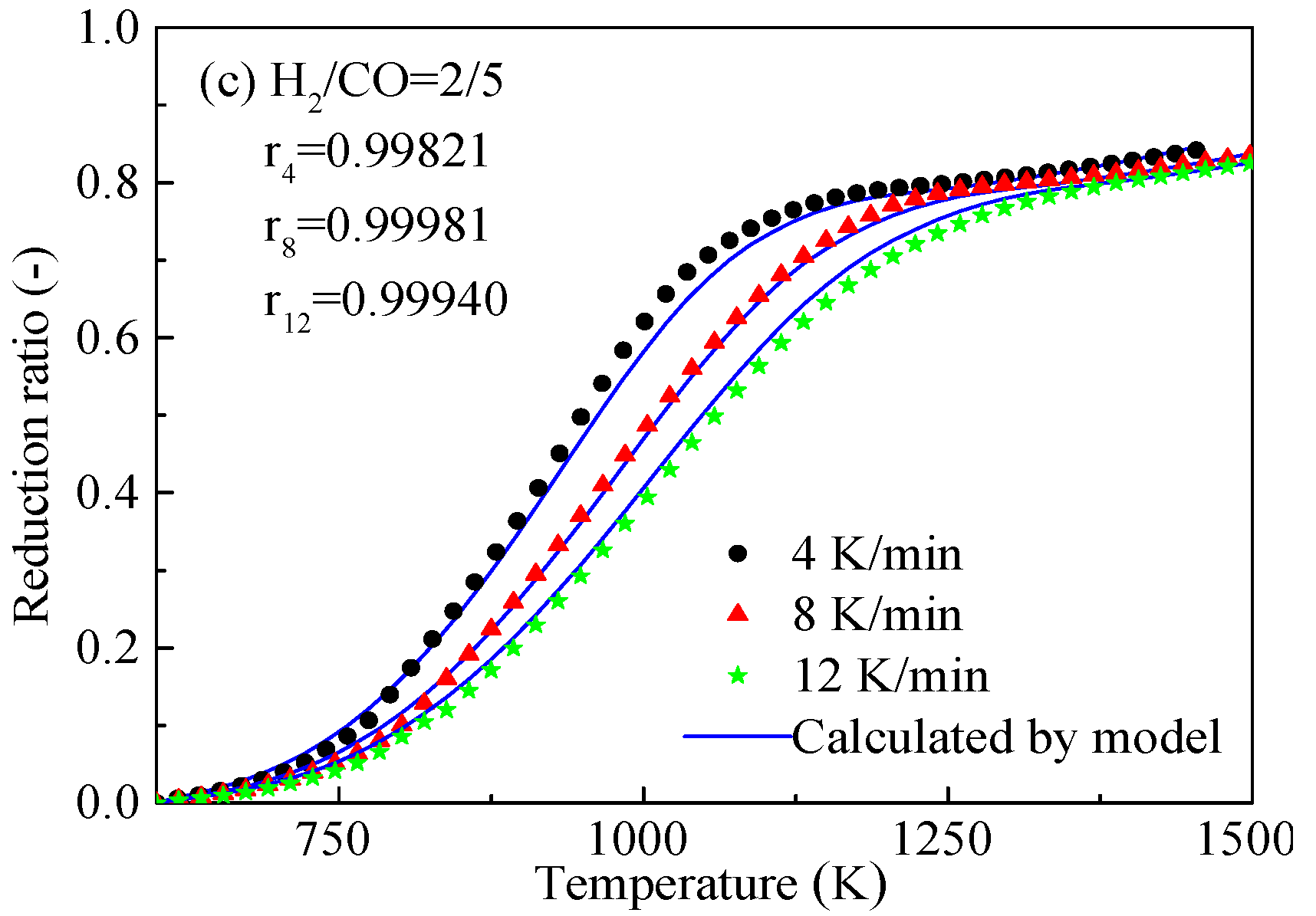
3.2. Effects of Heating Rate and Gas Composition on the HCVTM Pellet Reduction Ratio

The effects of the heating rate on the non-isothermal reduction ratio of HCVTM pellets under different reducing gas compositions are shown in Figure 10. According to the change rule of the reduction ratio, each of these plots could be divided into three distinct regions. Initially, the pellet reduction was insensitive and its rate was slow, indicating a modest reduction ratio. Then, the reduction accelerated suddenly at approximately 773 K, although the accurate turn temperature was slightly different with different heating rates. As the reduction proceeded, the reduction rate decreased due to the thickening product layer, and the reduction ratio nearly reached a high constant value. In addition, it is clear that the reduction ratio plots shifted to the right (to increasing temperature values) with an increasing heating rate. Moreover, the HCVTM pellets nearly reached the same reduction ratio under a given reducing gas composition, although the heating rates were different.
The effects of the reducing gas composition on the non-isothermal reduction ratio with different heating rates are presented in Figure 11. It is obvious that the reduction ratio reached a higher value with an increasing content of the H2 in the gas mixtures. This result is attributed to the accelerated reduction by the H2-rich atmosphere. The H2 molecule is smaller than the other gas molecules, which is conducive to a more effective diffusion. Moreover, according to the work of Ono-Nakazato et al. [21], some of the H2 molecules act as catalysts during the reduction. All these factors can accelerate and improve the reduction.

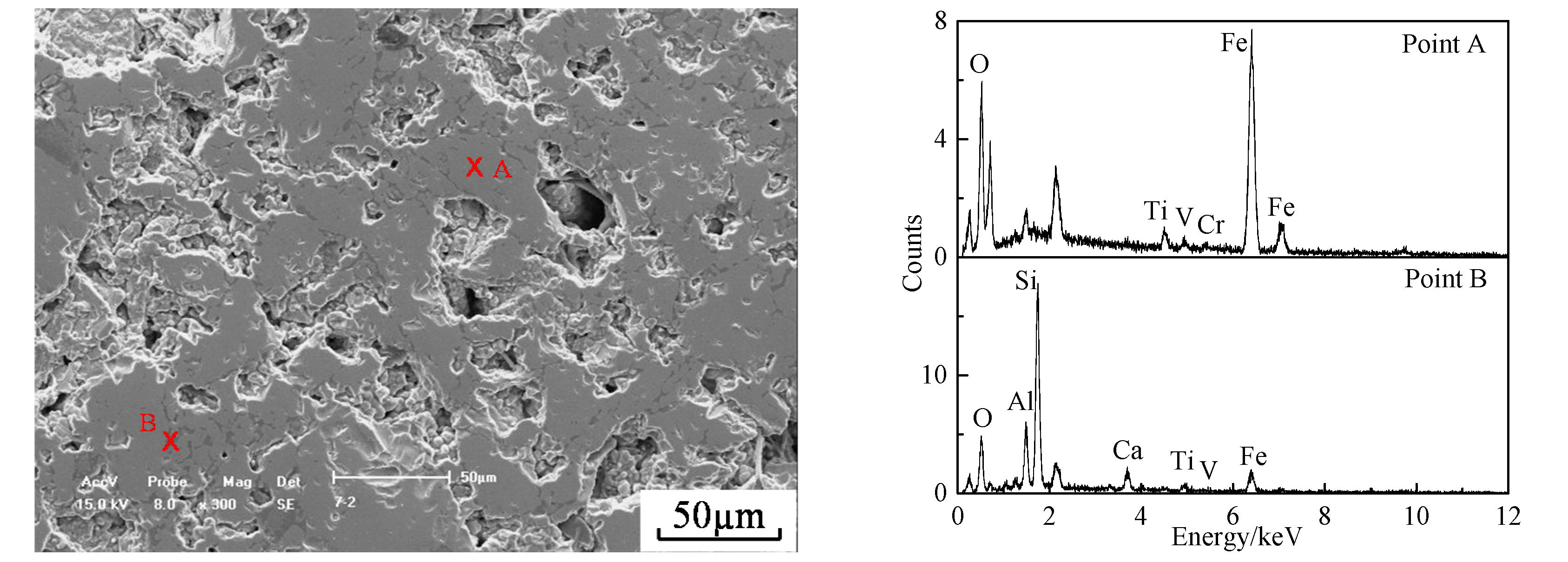
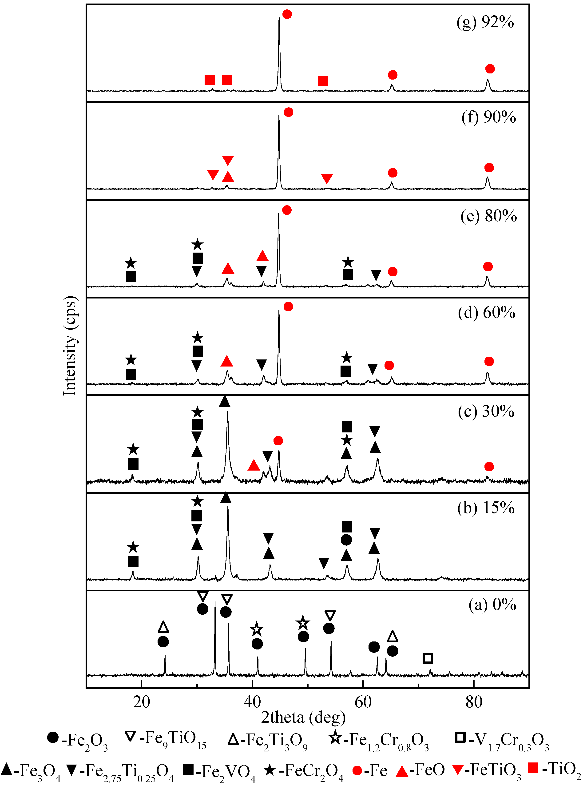
3.3. Phase Transformation and Morphologic Changes of the HCVTM Pellets During Reduction

To investigate the phase transformation during the gas-based reduction, the HCVTM pellets were reduced under a heating rate of 8 K/min and a gas composition of H2/CO = 5/2 and were analyzed by XRD. Several cases with a specific reduction ratio (0%, 15%, 30%, 60%, 80%, 90%, and 92%) were considered, and the results are given in Figure 12 and Table 3. As seen in Figure 12a, the main phases in the oxidized HCVTM pellets were hematite (Fe2O3), titanohematite (TTH, Fe9TiO15), pseudorutile (Fe2Ti3O9), Fe-Cr oxide solid solution (Fe1.2Cr0.8O3), and V-Cr oxide solid solution (V1.7Cr0.3O3). From Figure 12b, as the reduction proceeded, the reduction ratio reached 15%, and the diffraction peak of the hematite disappeared since it was transformed into magnetite (Fe3O4). Meanwhile, titanomagnetite (TTM, Fe2.75Ti0.25O4) was observed to be present, and the solid solutions including Fe-Cr and V-Cr were changed into chromite (FeCr2O4) and coulsonite (Fe2VO4), respectively. In Figure 12c, when the reduction ratio was 30%, metallic iron (Fe) was generated by further reduction, and the diffraction peak of wustite (FeO) was detected. However, by this time, the magnetite was still the dominant phase in the HCVTM pellets. As shown in Figure 12d, with the continuous removal of oxygen during the reduction process, the reduction ratio increased to 60%; although the phase compositions had no changes, the diffraction peaks for each existing phase were entirely different. Clearly, the magnetite and titanomagnetite peaks were both weakened, while the metallic iron peaks were enhanced. Meanwhile, wustite also showed an increasing tendency. In Figure 12e, further increasing the reduction ratio up to 80% had no obvious effects on the phase type, however, a slight decrease of wustite peak intensity as well as the sharpening Fe peaks could be found. As shown in Figure 12f, neither magnetite nor titanomagnetite could be detected at the reduction ratio of 90%, but the new ilmenite (FeTiO3) phase appeared. In Figure 12g, a further increase in the reduction ratio to 92% resulted in the presence of Ti in the form of titanium oxide (TiO2).
After the non-isothermal reduction by the H2-CO-CO2 mixtures was complete, the two detected phases in the final reduced HCVTM pellets were metallic iron (Fe) and titanium oxide (TiO2). The phases bearing V or Cr were not found after the reduction ratio of 80%, which might result from their relatively low content in HCVTM and the limitations of the analysis method. As the reduction proceeded, the diffraction peaks of the phases containing V or Cr became less sensitive. Therefore, in this work, the phase transformations of V or Cr are analyzed before the reduction ratio of 80%. V and Cr are present in the form of coulsonite (Fe2VO4) and chromite (FeCr2O4), respectively.
Notably, as seen from the XRD patterns in Figure 12, the peaks of the phases containing Ti, V, and Cr mostly overlapped, which was attributed to the close coexistence of these three elements in the HCVTM. Generally, V existed in an isomorphic form with Ti, and the occurrence of the Cr distribution was similar to that of V, as described in the work of He [22]. Meanwhile, the mineralogical investigation indicates that V and Cr concentrations above 97% were embedded into the titanomagnetite. In addition, the octahedral sites of the V and Cr were occupied by trivalent ions such as V (III) and Cr (III), similar to the results of Zhao [23]. Therefore, the phases bearing Ti, V, and Cr are usually found together with overlapped diffraction peaks, similar to the results of Zhou [24]. Currently, research concerning VTM or HCVTM utilizes XRD analysis as the main method to initially identify the formation of Ti-bearing phases, V-bearing phases, and Cr-bearing phases, as reported in many references. Therefore, based on the reasonable XRD analyses, the non-isothermal reduction of HCVTM pellets by gas mixtures can be speculated to proceed according to the following reactions, expressed in Equations (2)–(8). Here, the reduction by H2 is taken as an example.
(1)
When the reduction begins:
36Fe2O3 + 2Fe2Ti3O9 + 2Fe9TiO15 + 20H2 = 2Fe3O4 + 8 (3Fe3O4·Fe2TiO4) + 20H2O
Meanwhile, the phases containing V or Cr also cause some changes, as shown in Equations (2)–(5).
V1.7Cr0.3O3 = 0.85V2O3 + 0.15Cr2O3
Fe1.2Cr0.8O3 = 0.4Cr2O3 + 0.6Fe2O3
Fe3O4 + 3Cr2O3 + H2 = 3FeCr2O4 + H2O
4Fe3O4 + 3V2O3 + H2 = 6Fe2VO4 + H2O
(2)
When the reduction ratio is 15–90%:
Fe3O4 + 3Fe3O4·Fe2TiO4 + 14H2 = 11FeO + FeTiO3 + 14H2O
(3)
When the reduction ratio is more than 90%:
FeO + FeTiO3 + 2H2 = 2Fe + TiO2 + 2H2O
Therefore, the transformations of the key phases during the HCVTM pellet non-isothermal gas-based direct reduction are listed as follows: Fe2O3 → Fe3O4 → FeO → Fe; Fe9TiO15 + Fe2Ti3O9 → Fe2.75Ti0.25O4 → FeTiO3 → TiO2; V1.7Cr0.3O3 → V2O3 → Fe2VO4; Fe1.2Cr0.8O3 → Cr2O3 → FeCr2O4.
The morphology changes of the HCVTM pellets during the non-isothermal gas-based direct reduction were investigated by SEM analysis, as shown in Figure 13. The reduction swelling index (RSI) is defined as the volume change after reduction. The RSI changed with the increasing reduction ratio, as presented in Figure 14. Initially, (Figure 13a,b), the reduction began, and the compact recrystallization of the hematite was significantly destroyed, leading to the loose inner structure of the HCVTM pellets and the sharp increase of the RSI. As the reduction proceeded (Figure 13c), the reduction ratio increased to 60%, and the large-scale bright white metallic iron was found in the pellets, which agrees well with the results from the XRD analysis (Figure 13d). After further increasing the reduction ratio (Figure 13e,f), more metallic iron was generated, grew, and gradually gathered. Meanwhile, the generated metallic iron introduced the softening deformation at high reduction temperatures. Both the above functions are conducive to a decrease in the number of pores in the pellets. Accordingly, the RSI slightly decreased during the late stage of the reduction, as shown in Figure 14.

3.4. Non-Isothermal Gas-Based Direct Reduction Kinetics of HCVTM Pellets

The phases bearing V and Cr were difficult to reduce under the experimental temperatures and gas compositions. In addition, the amounts of V and Cr in the HCVTM were relatively low. Therefore, the possible reaction interfaces were confirmed by the transformations of the phases containing Fe and Ti when performing the kinetic analysis. According to the results of the XRD analysis and the conclusion of the phase transformation, the reactions are presented as Equations (9)–(11).
Fe2O3 + Fe2Ti3O9 + TTH + H2 (CO) → Fe3O4 + TTM + H2O (CO2)
Fe3O4 + TTM + H2 (CO) → FeO + FeTiO3 + H2O (CO2)
FeO + FeTiO3 + H2 (CO) → Fe + TiO2 + H2O (CO2)
It is concluded that the above reactions in Equations (9)–(11) occurred simultaneously. This gas-based reduction mechanism could be described by an initial reduction process among the hematite, pseudorutile, titanohematite, and the reducing gas at the outer surface of the particles, forming the magnetite and titanomagnetite. Once the magnetite and titanomagnetite formed, the second reaction proceeded immediately. Using this analogy, the third reaction began once the products of the second reaction (wustite and ilmenite) were generated. Therefore, it is assumed that the gas-based reduction of the HCVTM pellets proceeded topochemically and had three reaction fronts corresponding to Equations (9)–(11), as presented in Figure 15.
Based on earlier works [24,25], when there is only one reaction interface and the reducing gas is H2 or CO, the formula to describe the reduction ratio ξ of spherical particles is expressed as Equations (12) and (13), corresponding to the two cases of controlling the chemical reaction and controlling the diffusion in the product layer, respectively:
ξ = 1 ( 1 1 B C exp ( Δ E app R T ) t ) 3
ξ = 1 [ 1 1 B D exp ( Δ E app R T ) t ] 3
where BC and BD are the coefficients related to the chemical reaction and the diffusion in the product layer, respectively; ΔEapp is the apparent activation energy for the reaction, J/mol; R is the gas constant, J/(mol·K); T is the temperature at time t, K; and t is the reduction time, s.
In the present work, the relationship between the temperature and time is obtained from Equation (14):
t = T T 0 β
where T is the temperature at time t, K; T0 is the initial temperature, K; and β is the heating rate, K/min.
Therefore, Equations (12) and (13) can be expressed as into Equations (15) and (16), respectively.
ξ = 1 ( 1 1 B C exp ( Δ E app R T ) T T 0 β ) 3
ξ = 1 [ 1 1 B D exp ( Δ E app R T ) T T 0 β ] 3
For the non-isothermal reduction of the HCVTM pellets by gas mixtures, considering the reducing gas composition and the three reaction interfaces, the overall reduction ratio can be expressed as a linear summation, defined in Equation (17):
ξ = x H 2 ξ H 2 + x CO ξ CO = x H 2 ( α 1 H 2 ξ 1 H 2 + α 2 H 2 ξ 2 H 2 + α 3 H 2 ξ 3 H 2 ) + x CO ( α 1 CO ξ 1 CO + α 2 CO ξ 2 CO + α 3 CO ξ 3 CO )
where x H 2 and x CO are the mole fractions of H2 and CO, respectively, %; ξ H 2 and ξ CO are the reduction ratios by H2 and CO, respectively, %; ξ 1 H 2 , ξ 2 H 2 , and ξ 3 H 2 are the reduction ratios of Reactions (9)–(11) by H2, respectively, %; ξ 1 CO , ξ 2 CO , and ξ 3 CO are the reduction ratios of Reactions (9)–(11) by CO, respectively, %; α 1 H 2 , α 2 H 2 , and α 3 H 2 are the coefficients depending on the oxygen loss of Reactions (9)–(11) by H2, respectively; and α 1 CO , α 2 CO , and α 3 CO are the coefficients depending on the oxygen loss of Reactions (9)–(11) by CO, respectively. For simplicity, α was approximated according to hematite → magnetite, magnetite → wustite, and wustite → iron, namely, α 1 H 2 = α 1 CO = 1 / 9 , α 2 H 2 = α 2 CO = 2 / 9 , and α 3 H 2 = α 3 CO = 6 / 9 .
For Reaction (9), due to the three forming and growing product layers, including magnetite and titanomagnetite, wustite and ilmenite, and iron and titanium oxide, the diffusion of the reducing gas through the magnetite and titanomagnetite product layer was weakened. Moreover, a significant amount of H2 was consumed during the reactions at the interfaces of Reactions (10) and (11). Thus, maybe the diffusion in product layers was the restrictive step. For Reactions (10) and (11) as first seen in Figure 8, several pores remained in the outer products, which promoted gas diffusion. Second, if Reactions (10) and (11) are controlled by the diffusion in the product layer, then the reducing gas will run out before it diffuses into the first interface (9), and Reaction (9) will not occur. Hence, it is reasonable to speculate that Reactions (10) and (11) are most likely controlled by chemical reactions. These above assumptions were similarly applied by Chou when researching the reduction of metal oxides by H2 [25,26].
Based on the above, ξ 1 H 2 and ξ 1 CO are expressed as in Equation (16), while ξ 2 H 2 , ξ 3 H 2 , ξ 2 CO , and ξ 3 CO are expressed as in Equation (15). The overall reduction ratio is evaluated by Equation (18):
ξ = 1 x H 2 { 1 9 [ 1 exp ( Δ E app 1 H 2 R T ) B D 1 H 2 T T 0 β ] 3 + 2 9 [ 1 exp ( Δ E app 2 H 2 R T ) B C 2 H 2 T T 0 β ] 3 + 6 9 [ 1 exp ( Δ E app 3 H 2 R T ) B C 3 H 2 T T 0 β ] 3 } x CO { 1 9 [ 1 exp ( Δ E app 1 CO R T ) B D 1 CO T T 0 β ] 3 + 2 9 [ 1 exp ( Δ E app 2 CO R T ) B C 2 CO T T 0 β ] 3 + 6 9 [ 1 exp ( Δ E app 3 CO R T ) B C 3 CO T T 0 β ] 3 }
where x H 2 and x CO are the mole fractions in H2 and CO, respectively, %; Δ E app 1 H 2 , Δ E app 2 H 2 , Δ E app 3 H 2 , Δ E app 1 CO , Δ E app 2 CO , and Δ E app 3 CO are the apparent activation energies for Reactions (9)–(11) by H2 and CO, respectively, J/mol; T is the temperature at time t, K; T0 is the initial temperature, K; β is the heating rate, K/min; and B D 1 H 2 , B C 2 H 2 , B C 3 H 2 , B D 1 CO , B C 2 CO , and B C 3 CO are the coefficients related to the chemical reaction and diffusion when reduced by H2 and CO, respectively.
Using the non-isothermal experimental data and using a MATLAB program, the kinetic parameters of Equation (18) were obtained, as listed in Table 4. The final non-isothermal reduction kinetic model of the HCVTM pellets by gas mixtures can be expressed as Equation (19). When the heating rate along with the reducing gas composition is given, the specific non-isothermal reduction model for the HCVTM pellet by gas mixtures can be determined.
ξ = 1 x H 2 { 1 9 [ 1 exp ( 90 . 64 × 10 3 R T ) 0 . 68 × 10 - 2 T T 0 β ] 3 + 2 9 [ 1 exp ( 83 . 68 × 10 3 R T ) 8 . 68 × 10 - 2 T T 0 β ] 3 + 6 9 [ 1 exp ( 171 . 80 × 10 3 R T ) 4 . 60 × 10 - 2 T T 0 β ] 3 } x CO { 1 9 [ 1 exp ( 145 . 94 × 10 3 R T ) 1 . 56 × 10 - 2 T T 0 β ] 3 + 2 9 [ 1 exp ( 158 . 51 × 10 3 R T ) 7 . 10 × 10 - 2 T T 0 β ] 3 + 6 9 [ 1 exp ( 83 . 79 × 10 3 R T ) 4 . 20 × 10 - 2 T T 0 β ] 3 }
Here, x H 2 and x CO are the mole fractions of H2 and CO, respectively, %; T is the temperature at time t, K; T0 is the initial temperature, K; and β is the heating rate, K/min.
Figure 16 and Figure 17 show the calculated results and the experimental data of the non-isothermal reduction of HCVTM pellets by gas mixtures under different heating rates and gas compositions. From these data, the correlation coefficient was extracted, and all of the values were greater than 0.99. This result reveals that the kinetic model obtained based on the unreacted core model with multiple reaction interfaces can be effectively and properly used to describe the non-isothermal reduction of HCVTM pellets by gas mixtures.

3.5. Melting Separation of the Metallized HCVTM Pellets

The metallized HCVTM pellets with a reduction ratio of approximately 92% obtained at 1373 K with a heating rate of 8 K/min were applied for the melting separation. The chemical composition of the metallized HCVTM pellets is listed in Table 5. The temperature and time for the melting separation was controlled at 1923 K for 40 min. The patterns of the products, including the iron and separation slag, are shown in Figure 18. After the melting separation process was complete, the iron and slag were successfully separated, and the iron containing V and Cr with a relatively large density fell to the bottom of the crucible, while the light Ti-rich slag floated on top.
The compositions of the iron and separation slag were analyzed by ICP-OES, and the results are given in Table 6. The elemental recoveries were calculated according to the mass balance as defined in Equations (20) and (21). Through analysis and calculation, the recovery rates of Fe, V, and Cr in iron were found to be 99.45%, 98.83%, and 95.02%, respectively. The recovery rate of TiO2 in the slag was 95.08%. It is suggested that most of the V and Cr in the HCVTM was concentrated in the iron, and a large proportion of Ti was enriched into the so-called Ti-rich slag. Finally, the efficient separation of Fe, V, and Cr from Ti was successfully achieved by the novel process of gas-based direct reduction-melting separation. The Ti-rich slag can be used for titanium white production. However, more work is needed to further separate the V and Cr, such as an alternative method, a separation mechanism, or a metal recovery rate. This process will be the subject of future work.
R TiO 2 = ( W 2 × M S ) / ( W 1 × M P ) × 100 %
R M = ( W 4 × M I ) / ( W 3 × M P ) × 100 %
Here, R TiO 2 and R M are the recovery values of TiO2 in the slag and the elements (Fe, V and Cr) in the iron, respectively, %; W 1 and W 2 are the mass fractions of TiO2 in the metallized HCVTM pellets and slag, respectively, %; W 3 and W 4 are the mass fractions of the elements in the metallized HCVTM pellets and iron, respectively, %; and M P , M S , and M I are the masses of the metallized HCVTM pellets, slag, and iron, respectively, g.

4. Conclusions

(1)
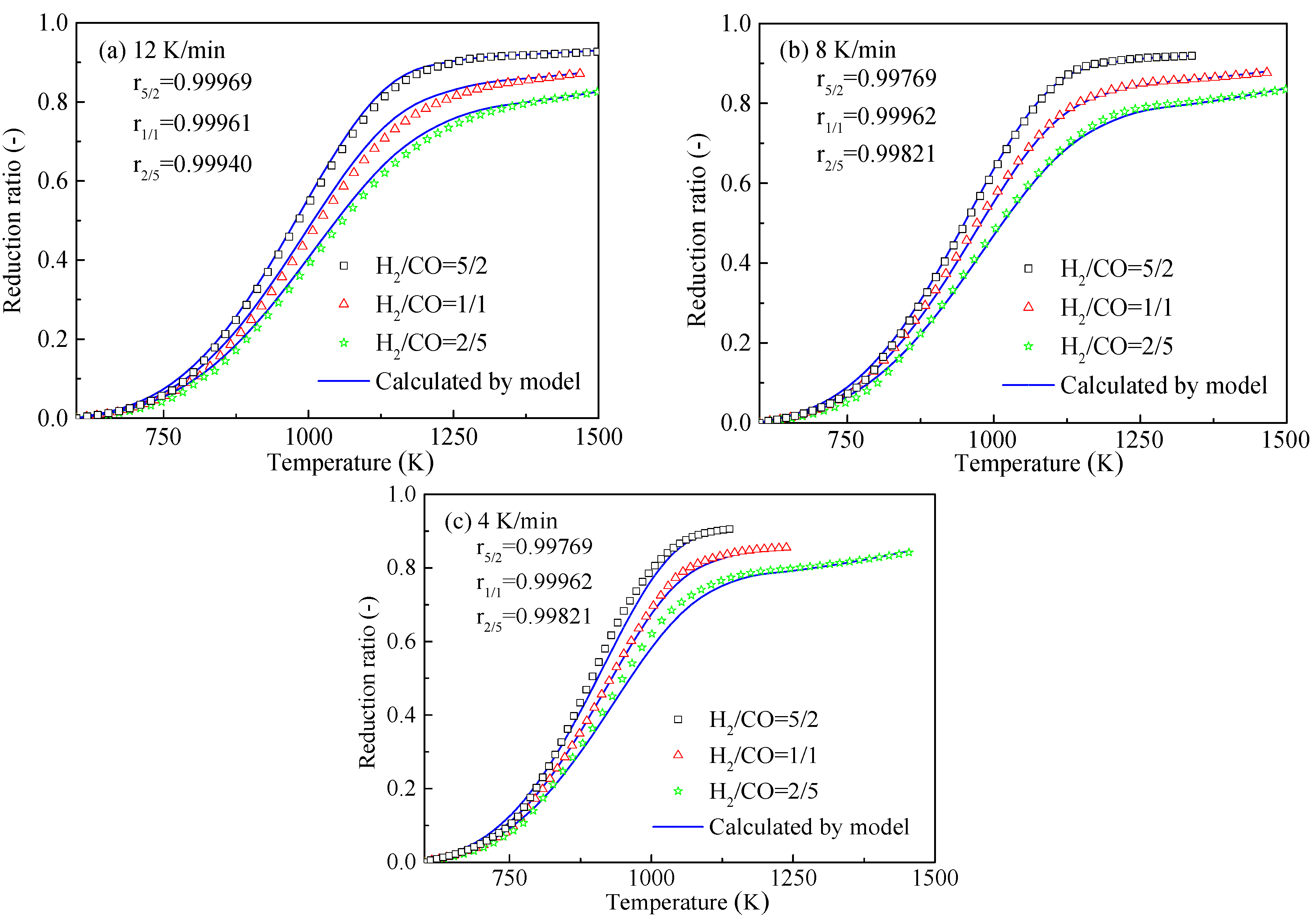
With the increase of the heating rate, the plot of the reduction ratio shifted to the right. The HCVTM pellets reached nearly the same reduction ratio under a given reducing gas composition, although the heating rates were different. Under the same heating rate, the gas mixture with more H2 was conducive for obtaining a higher reduction ratio.
(2)
The phase transformations of the HCVTM pellets during the non-isothermal reduction by the gas mixtures were ordered as follows: Fe2O3 → Fe3O4 → FeO → Fe; Fe9TiO15 + Fe2Ti3O9 → Fe2.75Ti0.25O4 → FeTiO3 → TiO2; V1.7Cr0.3O3 → V2O3 → Fe2VO4; Fe1.2Cr0.8O3 → Cr2O3 → FeCr2O4.
(3)
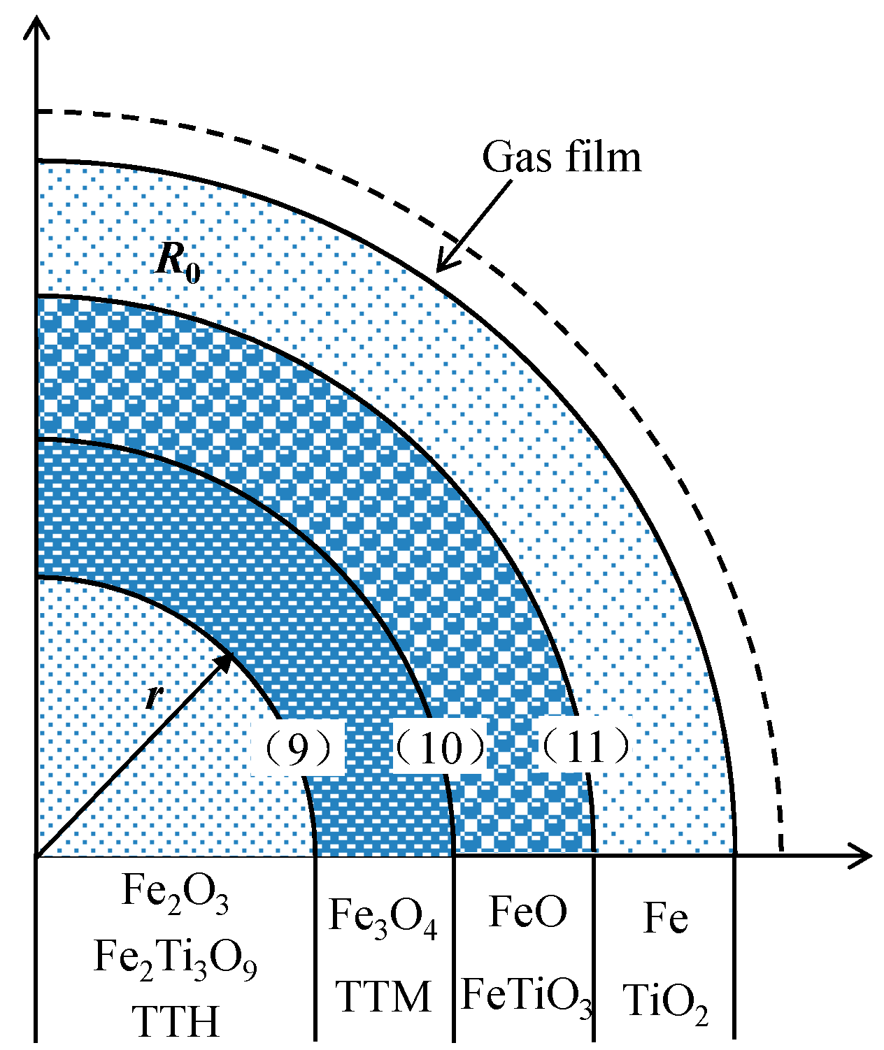
Based on the unreacted core model with multiple reaction interfaces, the kinetic model for the non-isothermal reduction of the HCVTM pellets by the gas mixtures was established as follows:
ξ = 1 x H 2 { 1 9 [ 1 exp ( 90 . 64 × 10 3 R T ) 0 . 68 × 10 - 2 T T 0 β ] 3 + 2 9 [ 1 exp ( 83 . 68 × 10 3 R T ) 8 . 68 × 10 - 2 T T 0 β ] 3 + 6 9 [ 1 exp ( 171 . 80 × 10 3 R T ) 4 . 60 × 10 - 2 T T 0 β ] 3 } x CO { 1 9 [ 1 exp ( 145 . 94 × 10 3 R T ) 1 . 56 × 10 - 2 T T 0 β ] 3 + 2 9 [ 1 exp ( 158 . 51 × 10 3 R T ) 7 . 10 × 10 - 2 T T 0 β ] 3 + 6 9 [ 1 exp ( 83 . 79 × 10 3 R T ) 4 . 20 × 10 - 2 T T 0 β ] 3 }
where x H 2 and x CO are the mole fractions in the gas mixtures, respectively, %; T is the temperature at time t, K; T0 is the initial temperature, K; and β is the heating rate, K/min. The correlation coefficients were all greater than 0.99, revealing that the kinetic model could be properly used to describe the non-isothermal reduction of HCVTM pellets by gas mixtures.
(4)
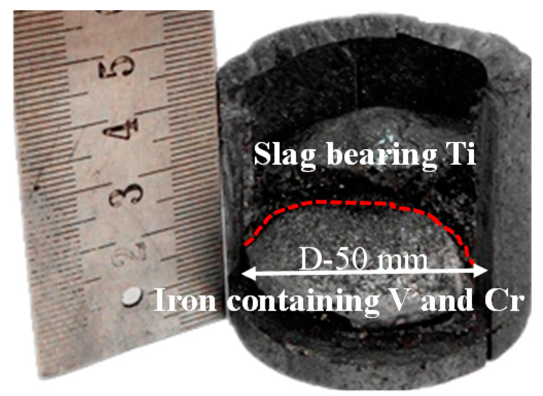
Through the melting separation of the metallized HCVTM pellets, the iron containing V and Cr along with the Ti-rich slag was obtained. The mass fraction and recovery rates of Fe, V, and Cr in iron were 93.87% and 99.45%, 0.91% and 98.83%, and 0.72% and 95.02%, respectively. The mass fraction and recovery rate of the TiO2 in the slag were 38.12% and 95.08%, respectively.
(5)
The gas-based direct reduction process is a really promising technology for the disposal of HCVTM. It has low carbon emission and is environment-friendly. Furthermore, the recoveries of valuable elements including Fe, V, Cr, and Ti could be improved significantly through the novel process. The subsequent assessment of production cost and other things should be considered comprehensively in future research.

Acknowledgments

The authors are especially grateful to the National Natural Science Foundation of China (Grant No. 51574067).

Author Contributions

Jue Tang, Man-Sheng Chu, Zi-Wei Ying conceived and designed the experiments; Jue Tang performed the experiments, analyzed the data, and compiled the text; Feng Li, Cong Feng, and Zheng-Gen Liu supervised the experimental work and reviewed the manuscript.

Conflicts of Interest

The authors declare no conflict of interest.

References

  1. Hu, M.; Liu, L.; Lv, X.; Bai, C.; Zhang, S. Crystallization Behavior of Perovskite in the Synthesized High-Titanium-Bearing Blast Furnace Slag Using Confocal Scanning Laser Microscope. Metall. Mater. Trans. B 2014, 45, 76–85. [Google Scholar] [CrossRef]
  2. Long, H.; Chun, T.; Wang, P.; Meng, Q.; Di, Z.; Li, J. Grinding Kinetics of Vanadium-Titanium Magnetite Concentrate in a Damp Mill and Its Properties. Metall. Mater. Trans. B 2016, 47, 1765–1772. [Google Scholar] [CrossRef]
  3. Zhang, L.; Zhang, W.; Zhang, J.; Li, G. Oxidation Kinetics and Oxygen Capacity of Ti-Bearing Blast Furnace Slag under Dynamic Oxidation Conditions. Metals 2016, 6, 105. [Google Scholar] [CrossRef]
  4. Zhou, W.; Xie, B.; Tan, W.F.; Diao, J.; Zhang, X.; Li, H.Y. Non-isothermal Crystallization Kinetics of Spinels in Vanadium Slag with High CaO Content. JOM 2016, 68, 2520–2524. [Google Scholar] [CrossRef]
  5. Tuo, X.; Xu, Z.; Teng, Y.; Mu, K. The Geochemical Characteristics of Heavy Metals in Soils in the Panzhihua V-Ti Magnetite Mine and the Pollution Evaluation. Bull. Mineral. Petrol. Geochem. 2007, 26, 127–131. [Google Scholar]
  6. Zhou, Y.; Yang, D.; Xie, Y.; Wang, P. Distribution Characteristics of Heavy Metals in Soils in Panzhihua V-Ti Magnetite Mine and Pollution Evaluation. Southwest China J. Agric. Sci. 2010, 23, 777–781. [Google Scholar]
  7. Chen, S.; Chu, M. Metalizing Reduction and Magnetic Separation of Vanadium Titano-magnetite Based on Hot Briquetting. J. Miner. Metall. Mater. 2014, 21, 225–233. [Google Scholar] [CrossRef]
  8. Sun, H.; Wang, J.; Han, Y.; She, X.; Xue, Q. Reduction Mechanism of Titanomagnetite Concentrate by Hydrogen. Int. J. Miner. Process. 2013, 125, 122–128. [Google Scholar] [CrossRef]
  9. Park, E.; Ostrovski, O. Reduction of Titania-Ferrous Ore by Carbon Monoxide. ISIJ Int. 2003, 43, 1316–1325. [Google Scholar] [CrossRef]
  10. Tang, J.; Chu, M.; Li, F.; Tang, Y.; Liu, Z.; Xue, X. Reduction Mechanism of High-chromium Vanadium–titanium Magnetite pellets by H2-CO-CO2 Gas Mixtures. Int. J. Miner. Metall. Mater. 2015, 22, 562–572. [Google Scholar] [CrossRef]
  11. Park, E.; Lee, S.B.; Ostrovski, O.; Min, D.J.; Rhee, C.H. Reduction of the Mixture of Titanomagnetite Ironsand and Hematite Iron Ore Fines by Carbon Monoxide. ISIJ Int. 2004, 44, 214–216. [Google Scholar] [CrossRef]
  12. Zhou, L.; Tao, D.; Fang, M.; Zeng, F.; Pu, X. Carbothermic Reduction of V-Ti Magnetite Ore. Chin. J. Rare Met. 2009, 33, 406–410. [Google Scholar]
  13. Jiang, T.; Wang, S.; Guo, Y.; Chen, F.; Zheng, F. Effects of Basicity and MgO in Slag on the Behaviors of Smelting Vanadium Titanomagnetite in the Direct Reduction-Electric Furnace Process. Metals 2016, 6, 107. [Google Scholar] [CrossRef]
  14. Hu, T.; Lv, X.; Bai, C.; Lun, Z.; Qiu, G. Reduction Behavior of Panzhihua Titanomagnetite Concentrates with Coal. Metall. Mater. Trans. B. 2013, 44, 252–260. [Google Scholar] [CrossRef]
  15. Cheng, G.; Liu, J.; Liu, Z.; Chu, M.; Xue, X. Non-isothermal Reduction Mechanism and Kinetics of High Chromium Vanadium–titanium Magnetite pellets. Ironmak. Steelmak. 2015, 42, 17–26. [Google Scholar] [CrossRef]
  16. Wang, M.; Zhou, S.; Wang, X.; Chen, B.; Yang, H.; Wang, S.; Luo, P. Recovery of Iron from Chromium Vanadium-Bearing Titanomagnetite Concentrate by Direct Reduction. JOM 2016, 68, 2698–2703. [Google Scholar] [CrossRef]
  17. Zhang, P. Basic Technology Study on Gas-based Direct Reduction for Indonesia Vanadium-Titanium Magnetite. Master’s Thesis, Northeastern University, Shenyang, China, 2014. [Google Scholar]
  18. Li, Y. Basic Research on Gas-based Reduction of Indonesia Ironsand Oxidized Pellets. Ph.D. Thesis, University of Science and Technology Beijing, Beijing, China, 2015. [Google Scholar]
  19. Zhang, J.; Zheng, C.; Tang, Y.; Chai, F. Reduction of Panzhihua titanium-bearing oxidized pellets by CO-N2-H2 gas. J. Cent. South Univ. 2016, 23, 1015–1022. [Google Scholar] [CrossRef]
  20. Park, E.; Ostrovski, O. Reduction of Titania-ferrous Ore by Hydrogen. ISIJ Int. 2004, 44, 999–1005. [Google Scholar] [CrossRef]
  21. Ono, N.H.; Yonezawa, T.; Usui, T. Effect of Water-Gas Shift Reaction on Reduction of Iron Oxide Powder Packed Bed with H2-CO Mixtures. ISIJ Int. 2003, 43, 1502–1511. [Google Scholar]
  22. He, G.; Du, X.; Zhang, K.; Tang, Z.; Lou, T.; Tu, G. Research on the Process of Deep Reduction-smelting Separation of Hongge Ore and the Trend of V, Cr. J. Mater. Metall. 2014, 13, 15–19. [Google Scholar]
  23. Zhao, L.; Wang, L.; Chen, D.; Zhao, H.; Liu, Y.; Qi, T. Behaviors of Vanadium and Chromium in Coal-based Direct Reduction of High-chromium Vanadium-bearing Titanomagnetite Concentrates Followed by Magnetic Separation. Trans. Nonferrous Met. Soc. China 2015, 25, 1325–1331. [Google Scholar] [CrossRef]
  24. Zhou, M.; Yang, S.; Jiang, T.; Xue, X. Influence of MgO in Form of Magnesite on Properties and Mineralogy of High Chromium, Vanadium, Titanium Magnetite Sinters. Ironmak. Steelmak. 2015, 42, 217–225. [Google Scholar] [CrossRef]
  25. Dang, J.; Chou, K.; Hu, X.; Zhang, G. Reduction Kinetics of Metal Oxides by Hydrogen. Steel Res. Int. 2013, 84, 526–533. [Google Scholar] [CrossRef]
  26. Chou, K. A Kinetic Model for Oxidation of Si-Al-O-N Materials. J. Am. Ceram. Soc. 2006, 89, 1568–1576. [Google Scholar] [CrossRef]
Figure 1. Particle size distribution of raw HCVTM concentrate.
Metals 07 00153 g001
Figure 2. The outline process chart of the novel process for disposing of HVCTM.
Metals 07 00153 g002
Figure 3. Pelletizing and Oxidizing process of HCVTM.
Metals 07 00153 g003
Figure 4. Particle size distribution of HCVTM concentrate after grinding for 15 min.
Metals 07 00153 g004
Figure 5. Picture of oxidized HCVTM pellets.
Metals 07 00153 g005
Figure 6. Schematic of the laboratory gas-based shaft furnace.
Metals 07 00153 g006
Figure 7. Schematic of the medium frequency induction furnace.
Metals 07 00153 g007
Figure 8. XRD analysis of the oxidized HCVTM pellets.
Metals 07 00153 g008
Figure 9. Scanning electron microscopy-energy dispersive spectrometer (SEM-EDS) analysis of the oxidized HCVTM pellets (A—gray phase; B—dark gray phase).
Metals 07 00153 g009
Figure 10. Effects of the heating rate on the non-isothermal reduction ratio under different reducing gas compositions (a) H2/CO = 5/2; (b) H2/CO = 1/1; (c) H2/CO = 2/5.
Metals 07 00153 g010
Figure 11. Effects of the reducing gas composition on the non-isothermal reduction ratio with different heating rates (a) 12 K/min; (b) 8 K/min; (c) 4 K/min.
Metals 07 00153 g011
Figure 12. XRD analysis of the HCVTM pellets with different reduction ratios, (a) 0% (b) 15% (c) 30% (d) 60% (e) 80% (f) 90% (g) 92%.
Metals 07 00153 g012
Figure 13. Morphology changes of the HCVTM pellets during the non-isothermal gas-based direct reduction ratios. (a) 15%; (b) 30%; (c) 60%; (d) 80%; (e) 90%; (f) 92%.
Metals 07 00153 g013
Figure 14. Changes in the reduction swelling index (RSI) with the increasing reduction ratio.
Metals 07 00153 g014
Figure 15. Schematic diagram of the interface progressions for the gas-based reduction of the HCVTM pellets.
Metals 07 00153 g015
Figure 16. Comparison between the experimental and calculated non-isothermal reduction ratio with different heating rates (a) H2/CO = 5/2; (b) H2/CO = 1/1; (c) H2/CO = 2/5.
Metals 07 00153 g016aMetals 07 00153 g016b
Figure 17. Comparison between the experimental and calculated non-isothermal reduction ratio with different gas compositions (a) 12 K/min; (b) 8 K/min; (c) 4 K/min.
Metals 07 00153 g017
Figure 18. Patterns of melting separation products.
Metals 07 00153 g018
Table 1. Chemical composition of high chromium vanadium-titanium magnetite (HCVTM) and bentonite (wt %).
ItemTFeV2O5Cr2O3TiO2Al2O3SiO2MgOCaOSPNa2OK2O
HCVTM62.120.950.615.053.182.120.920.220.040.01--
Bentonite----14..4767.454.612.47--1.681.19
Table 2. Chemical composition of the oxidized HCVTM pellets (wt %).
TFeFeOTiO2V2O5Cr2O3Al2O3SiO2MgOCaO
59.460.504.490.910.593.072.031.030.21
Table 3. Phase compositions of the HCVTM pellets at different reduction ratios.
Reduction Ratio (%)Phase Composition
0Fe2O3, Fe9TiO15, V1.7Cr0.3O3, Fe1.2Cr0.8O3, Fe2Ti3O9
15Fe3O4, Fe2.75Ti0.25O4, Fe2VO4, FeCr2O4
30Fe, Fe3O4, FeO, Fe2.75Ti0.25O4, Fe2VO4, FeCr2O4
60Fe, Fe3O4, FeO, Fe2.75Ti0.25O4, Fe2VO4, FeCr2O4
80Fe, Fe3O4, FeO, Fe2.75Ti0.25O4, Fe2VO4, FeCr2O4
90Fe, FeO, FeTiO3
92Fe, TiO2
Table 4. The kinetic parameters for the non-isothermal reduction model for HCVTM pellets by gas mixtures.
Parameter Δ E app × 10 3 (J/mol)
Δ E app 1 H 2 Δ E app 2 H 2 Δ E app 3 H 2 Δ E app 1 CO Δ E app 2 CO Δ E app 2 CO
Value90.6483.98171.80145.94158.5183.79
Parameter B C   or   B D × 10 2 (-)
B D 1 H 2 B C 2 H 2 B C 3 H 2 B D 1 CO B C 2 CO B C 3 CO
Value0.688.864.601.567.104.20
Table 5. Chemical composition of the metallized HCVTM pellet (wt %).
TFeMFeTiO2V2O5Cr2O3Al2O3SiO2MgOCaO
76.6470.019.2411.3340.8994.263.161.510.34
Table 6. Main chemical compositions of separated iron and slag (wt %).
Composition of Iron/%
TFeVCrTiSiSP-
93.870.910.720.560.0340.0270.041-
Composition of Slag/%
TFeVCrTiO2CaOSiO2MgOAl2O3
1.820.0380.13338.2121.3013.456.5518.48

