Investigation on Porosity and Microhardness of 316L Stainless Steel Fabricated by Selective Laser Melting


Abstract
:1. Introduction
2. Materials and Methods
3. Results and Discussion
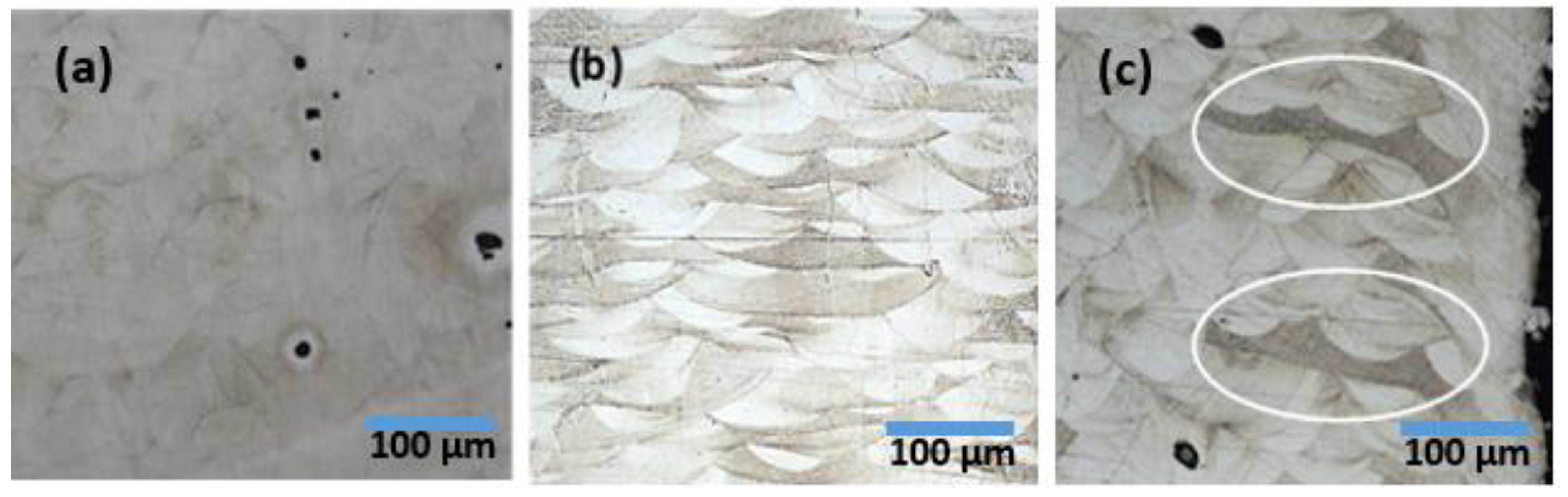
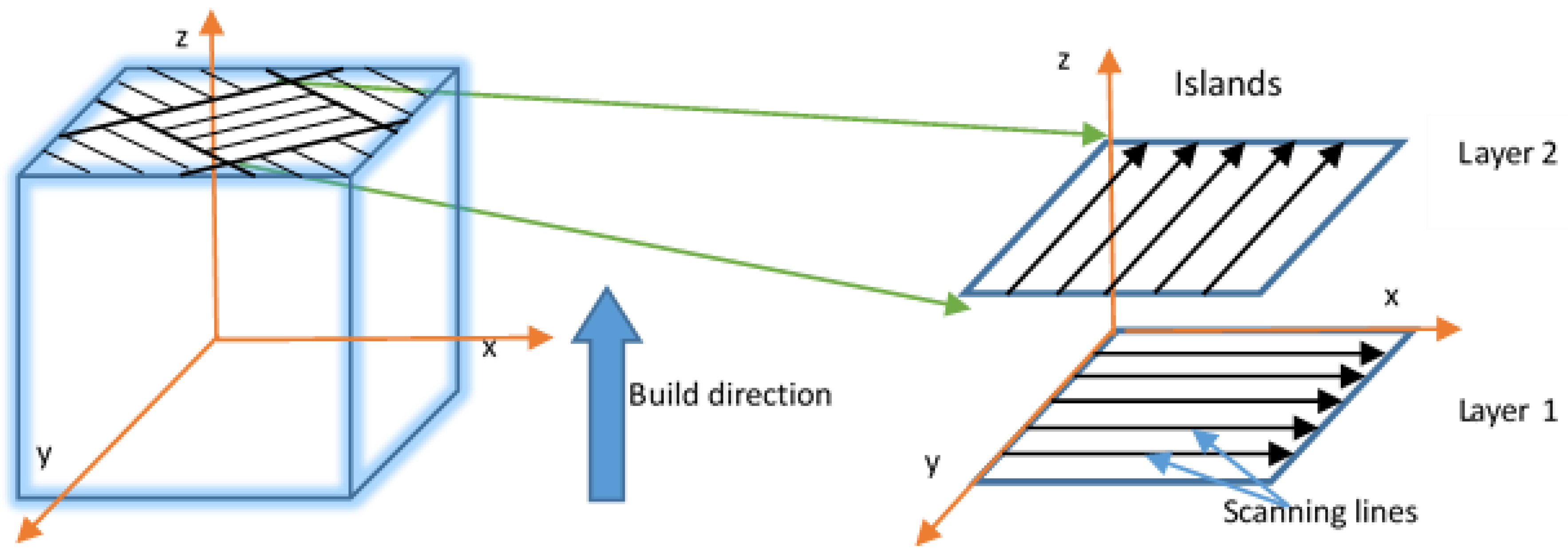
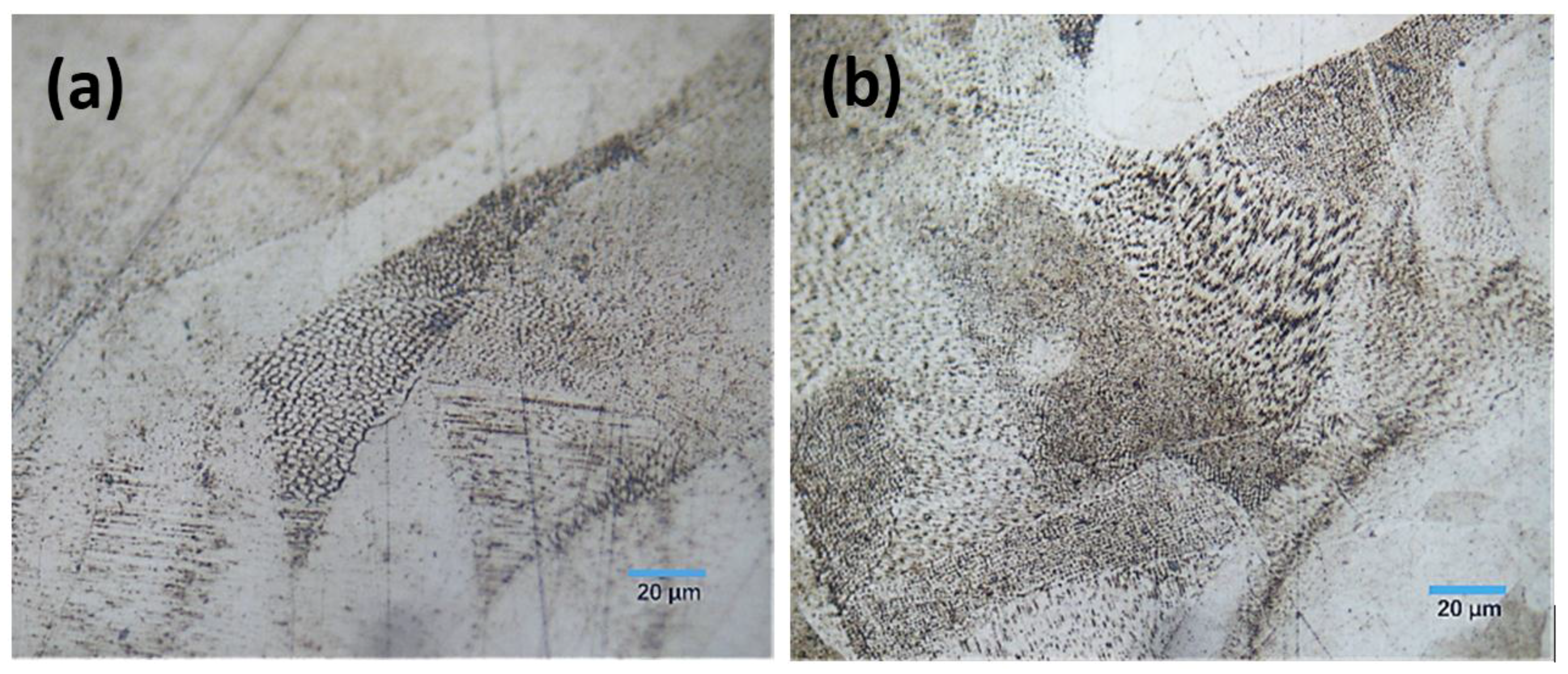
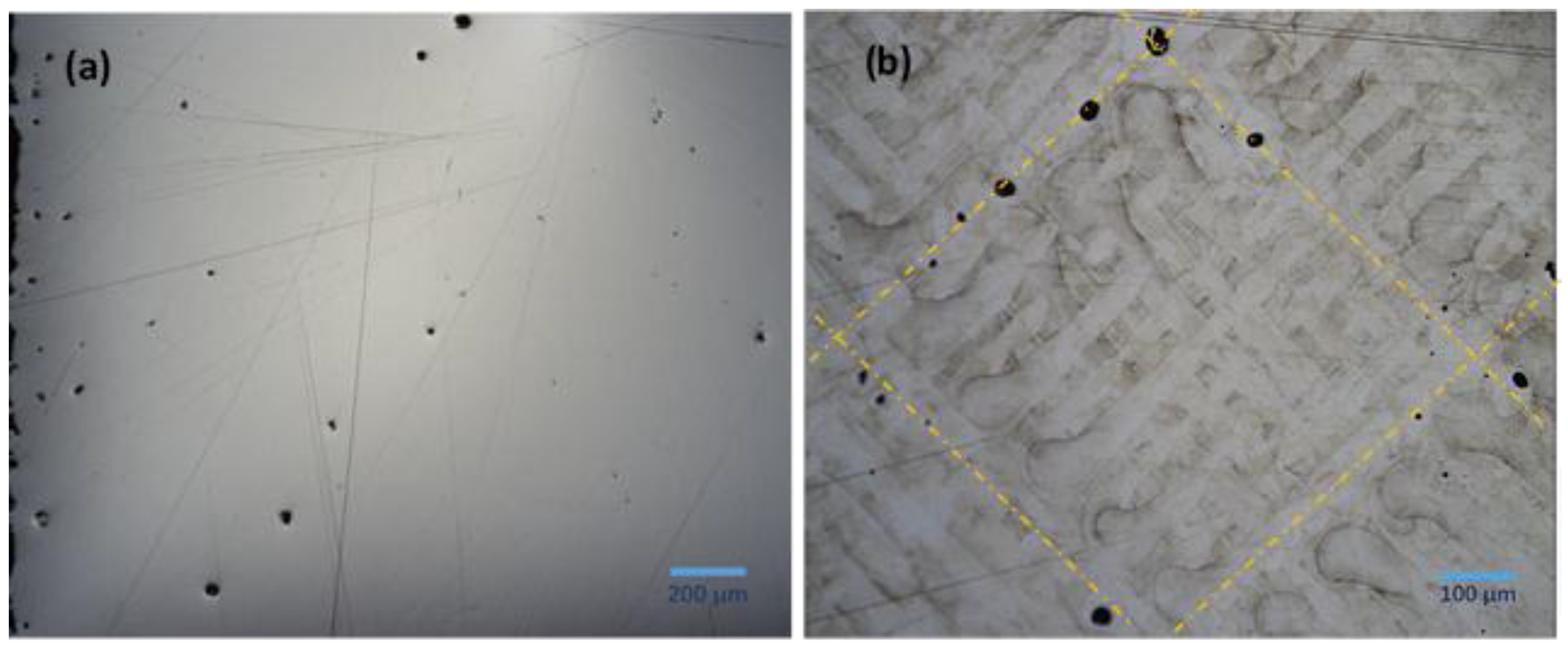
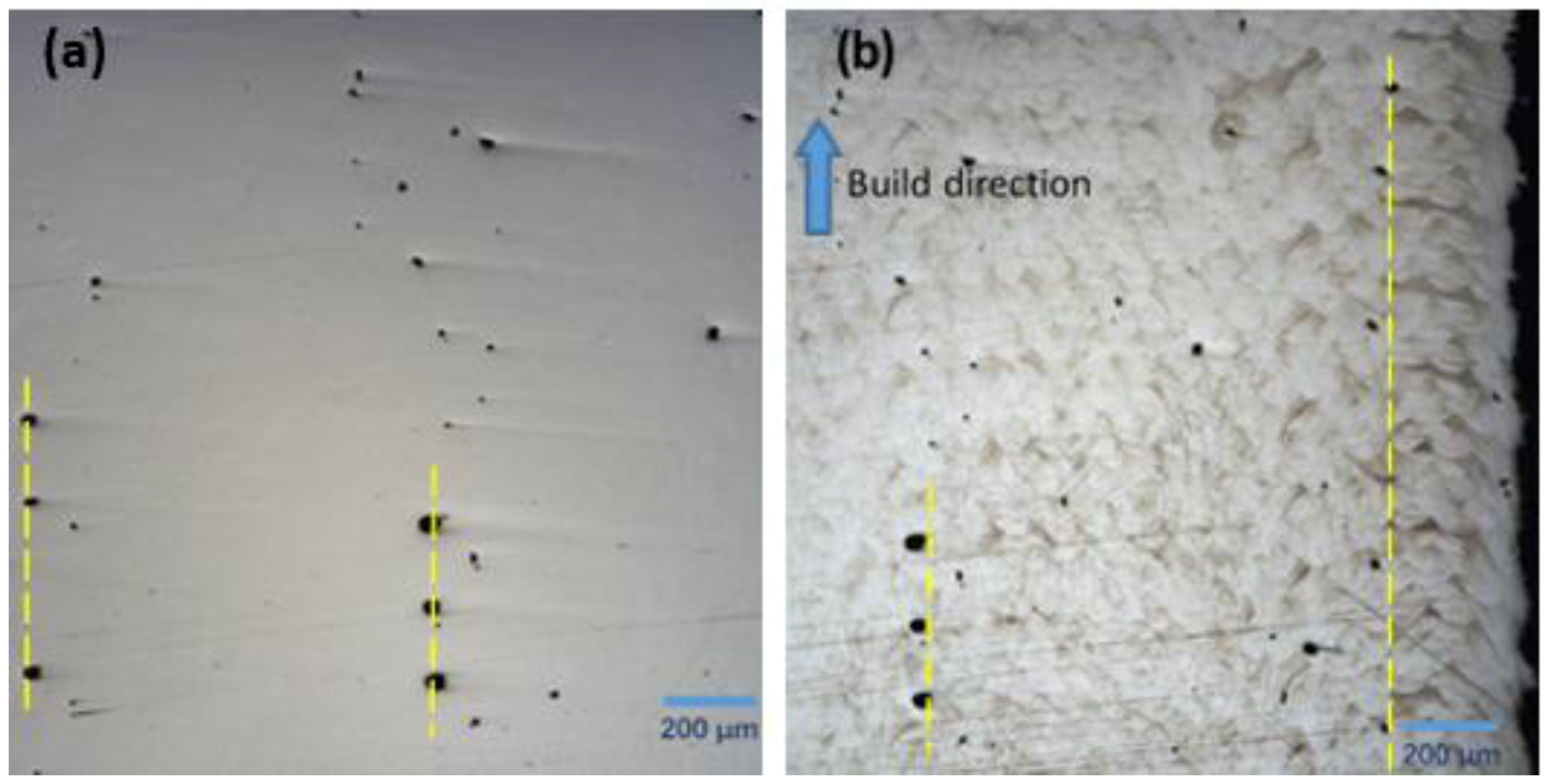
3.1. Microstructure
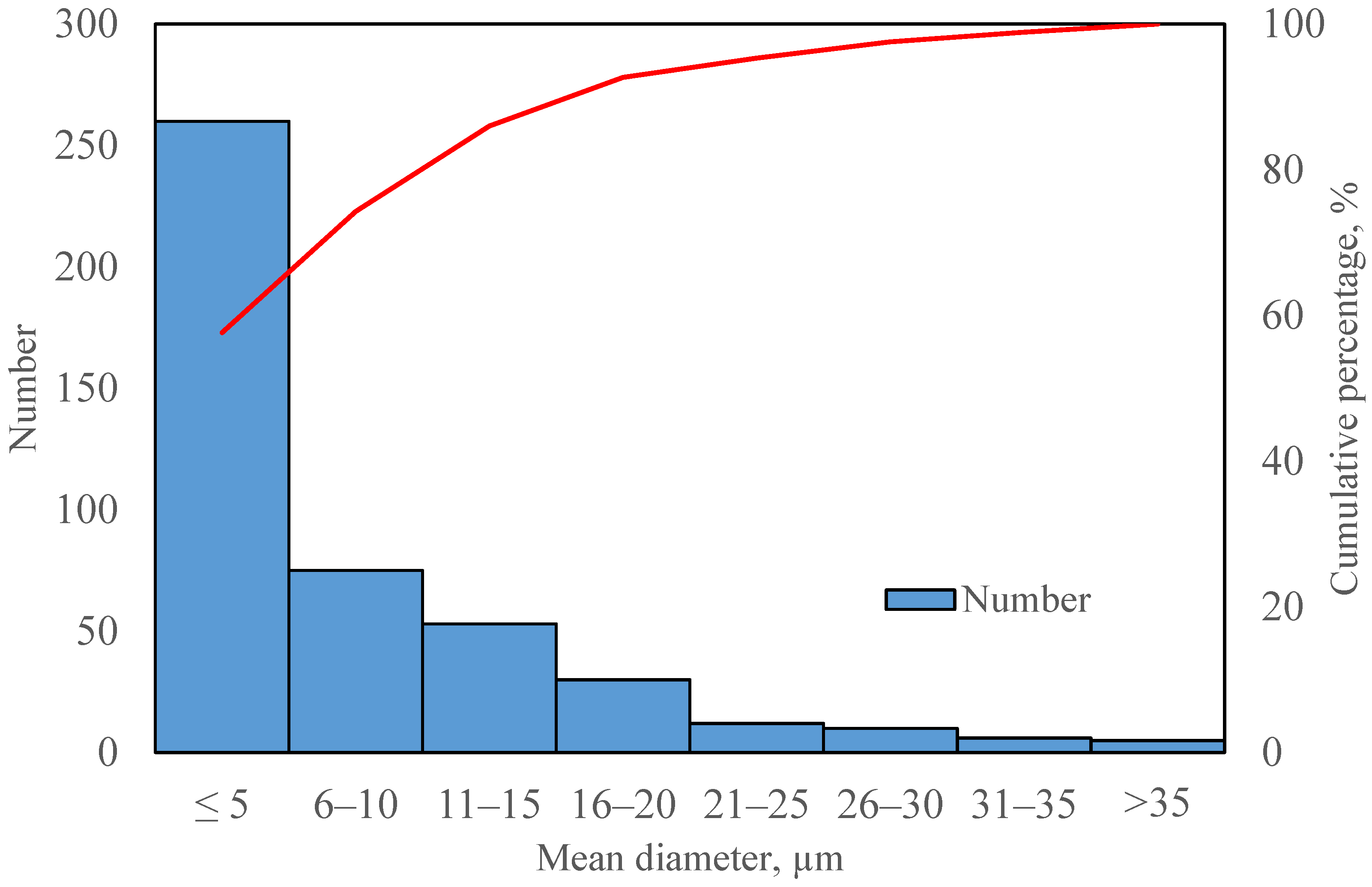
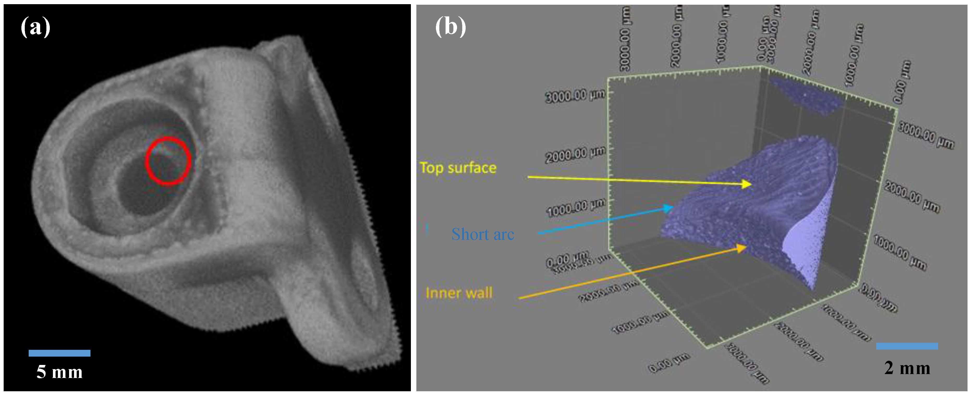
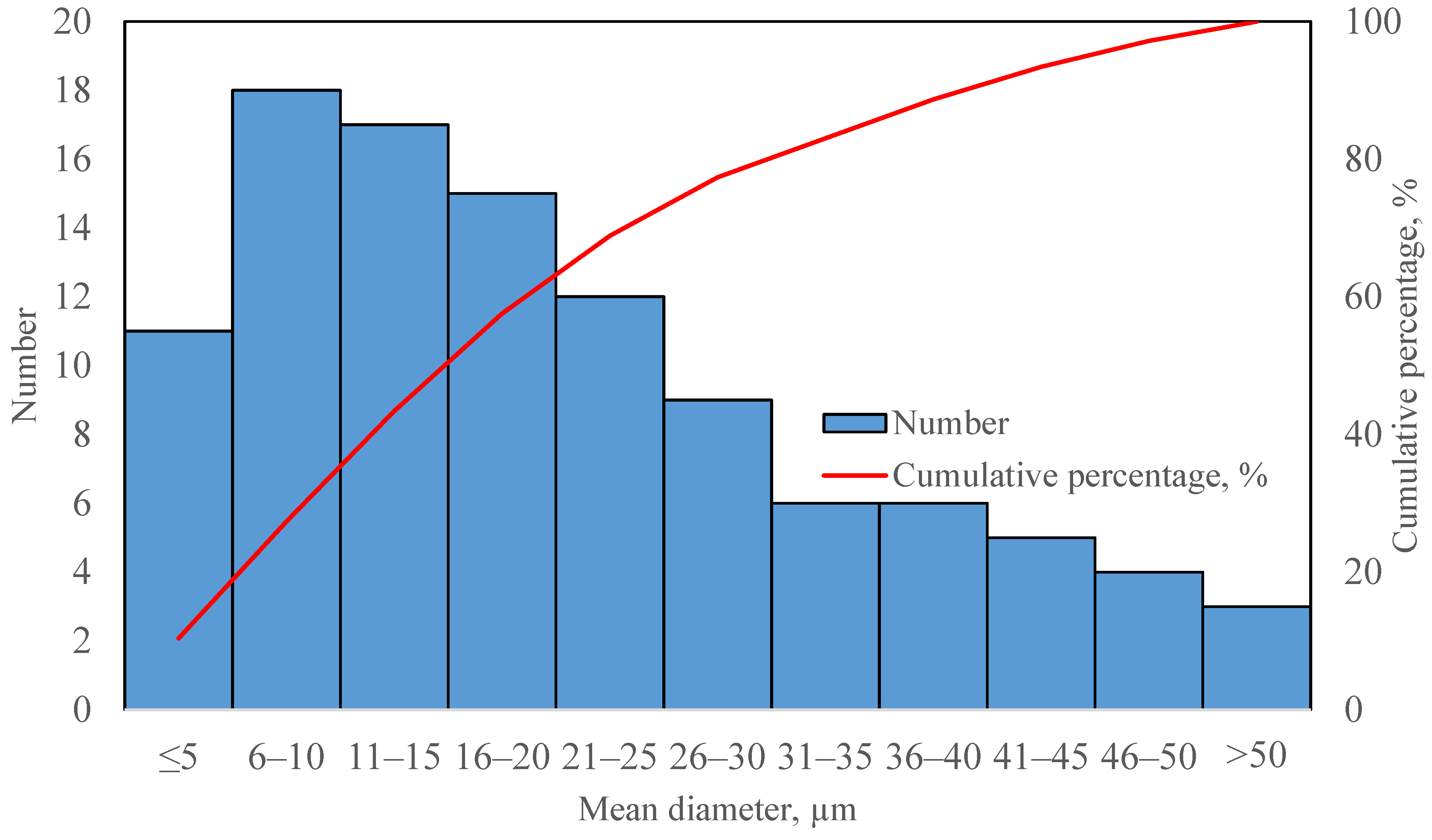
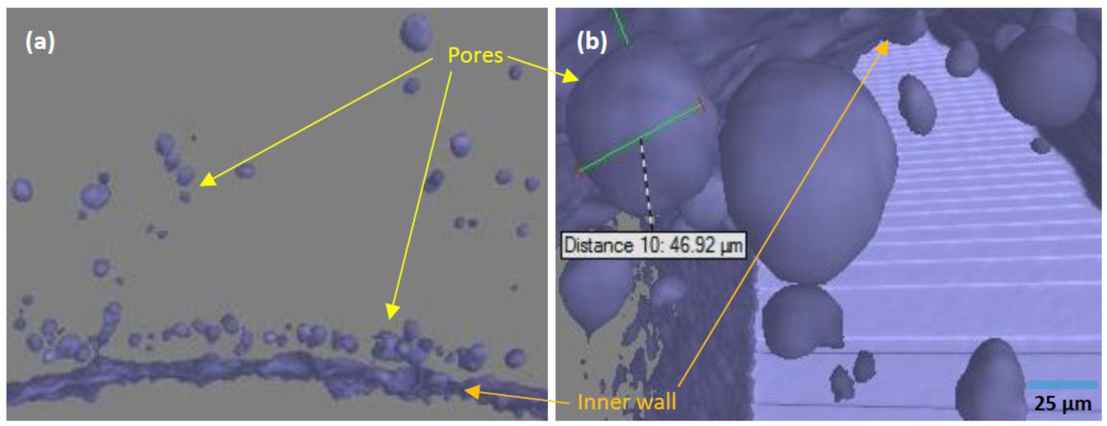
3.2. Porosity
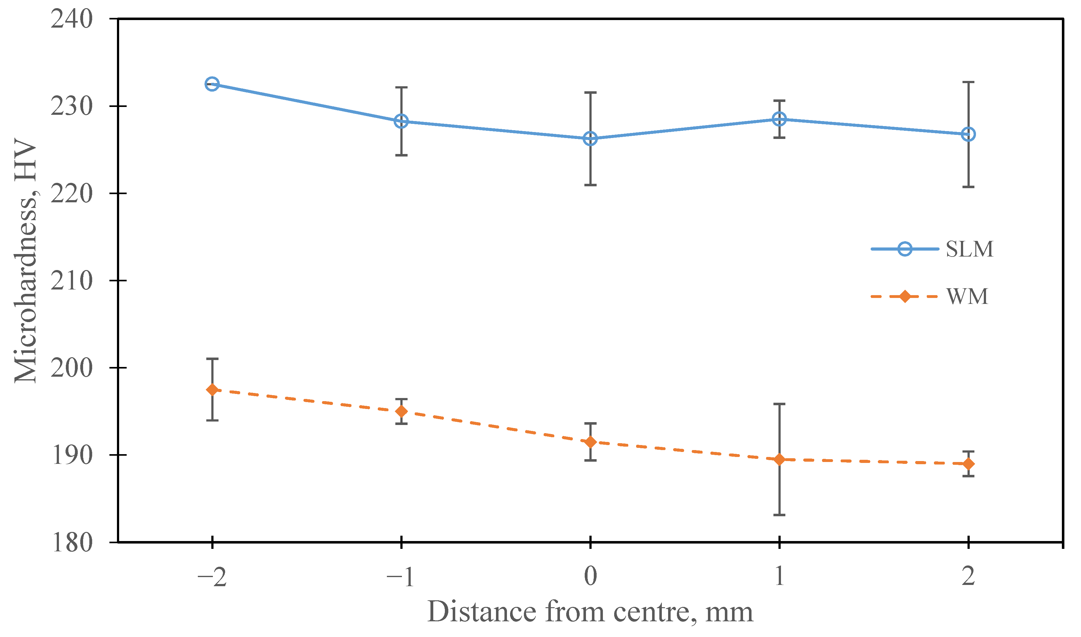
3.3. Microhardness
4. Conclusions
Author Contributions
Conflicts of Interest
References
- Cherry, J.A.; Davies, H.M.; Mehmood, S.; Lavery, N.P.; Brown, S.G.R.; Sienz, J. Investigation into the effect of process parameters on microstructural and physical properties of 316L stainless steel parts by selective laser melting. Int. J. Adv. Manuf. Technol. 2014, 76, 869–879. [Google Scholar] [CrossRef]
- Yusuf, S.M.; Gao, N. Influence of energy density on metallurgy and properties in metal additive manufacturing. Mater. Sci. Technol. 2017. [Google Scholar] [CrossRef]
- Guo, N.; Leu, M.C. Additive manufacturing: Technology, applications and research needs. Front. Mech. Eng. 2013, 8, 215–243. [Google Scholar] [CrossRef]
- Zhang, L.C.; Attar, H. Selective Laser Melting of Titanium Alloys and Titanium Matrix Composites for Biomedical Applications: A Review. Adv. Eng. Mater. 2016, 4, 463–475. [Google Scholar] [CrossRef]
- Frazier, W.E. Metal Additive Manufacturing: A Review. J. Mater. Eng. Perform. 2014, 23, 1917–1928. [Google Scholar] [CrossRef]
- Gu, D.D.; Meiners, W.; Wissenbach, K.; Poprawe, R. Laser additive manufacturing of metallic components: Materials, processes and mechanisms. Int. Mater. Rev. 2012, 57, 133–164. [Google Scholar] [CrossRef]
- Rafi, H.K.; Karthik, N.V.; Gong, H.; Starr, T.L.; Stucker, B.E. Microstructures and mechanical properties of Ti6Al4V parts fabricated by selective laser melting and electron beam melting. J. Mater. Eng. Perform. 2013, 22, 3872–3883. [Google Scholar] [CrossRef]
- Liu, Y.J.; Li, S.J.; Wang, H.L.; Hou, W.T.; Hao, Y.L.; Yang, R.; Sercombe, T.B.; Zhang, L.C. Microstructure, defects and mechanical behavior of beta-type titanium porous structures manufactured by electron beam melting and selective laser melting. Acta Mater. 2016, 113, 56–67. [Google Scholar] [CrossRef]
- Liu, Y.J.; Wang, H.L.; Li, S.J.; Wang, S.G.; Wang, W.J.; Hou, W.T.; Hao, Y.L.; Yang, R.; Zhang, L.C. Compressive and fatigue behavior of beta-type titanium porous structures fabricated by electron beam melting. Acta Mater. 2017, 126, 58–66. [Google Scholar] [CrossRef]
- Liu, F.; Lin, X.; Yang, G.; Song, M.; Chen, J.; Huang, W. Microstructure and residual stress of laser rapid formed Inconel 718 nickel-base superalloy. Opt. Laser Technol. 2011, 43, 208–213. [Google Scholar] [CrossRef]
- Riemer, A.; Leuders, S.; Thöne, M.; Richard, H.A.; Tröster, T.; Niendorf, T. On the fatigue crack growth behavior in 316L stainless steel manufactured by selective laser melting. Eng. Fract. Mech. 2013, 120, 15–25. [Google Scholar] [CrossRef]
- Hao, L.; Dadbakhsh, S.; Seaman, O.; Felstead, M. Selective laser melting of a stainless steel and hydroxyapatite composite for load-bearing implant development. J. Mater. Process. Technol. 2009, 209, 5793–5801. [Google Scholar] [CrossRef]
- Mathisen, M.B. In-Situ Tensile Testing Combined with EBSD Analysis of Ti-6Al-4V Samples from Components Fabricated by Additive Layer Manufacture. Master’s Thesis, Norwegian University of Science and Technology, Trondheim, Norway, June 2012. [Google Scholar]
- Yan, C.; Hao, L.; Hussein, A.; Young, P.; Raymont, D. Advanced lightweight 316L stainless steel cellular lattice structures fabricated via selective laser melting. Mater. Des. 2014, 55, 533–541. [Google Scholar] [CrossRef] [Green Version]
- Verlee, B.; Dormal, T.; Lecomte-Beckers, J. Density and porosity control of sintered 316L stainless steel parts produced by additive manufacturing. Powder Metall. 2012, 55, 260–267. [Google Scholar] [CrossRef]
- Dewidar, M.; Khalil, A.; Lim, J.K. Processing and mechanical properties of porous 316L stainless steel for biomedical applications. Trans. Nonferr. Met. Soc. China 2007, 17, 468–473. [Google Scholar] [CrossRef]
- AlMangour, B.; Grzesiak, D.; Yang, J.M. Selective laser melting of TiC reinforced 316L stainless steel matrix nanocomposites: Influence of starting TiC particle size and volume content. Mater. Des. 2016, 104, 141–151. [Google Scholar] [CrossRef]
- AlMangour, B.; Grzesiak, D.; Yang, J.M. Rapid fabrication of bulk-form TiB2/316L stainless steel nanocomposites with novel reinforcement architecture and improved performance by selective laser melting. J. Alloy. Compd. 2016, 680, 480–493. [Google Scholar] [CrossRef]
- AlMangour, B.; Grzesiak, D.; Yang, J.M. Selective laser melting of TiB 2/316L stainless steel composites: The roles of powder preparation and hot isostatic pressing post-treatment. Powder Technol. 2017, 309, 37–48. [Google Scholar] [CrossRef]
- Yasa, E.; Kruth, J.P. Microstructural investigation of Selective Laser Melting 316L stainless steel parts exposed to laser re-melting. Proced. Eng. 2011, 19, 389–395. [Google Scholar] [CrossRef]
- Jinhui, L.; Ruidi, L.; Wenxian, Z.; Liding, F.; Huashan, Y. Study on formation of surface and microstructure of stainless steel part produced by selective laser melting. Mater. Sci. Technol. 2010, 26, 1259–1264. [Google Scholar] [CrossRef]
- Carter, L.N.; Martin, C.; Withers, P.J.; Attallah, M.M. The influence of the laser scan strategy on grain structure and cracking behaviour in SLM powder-bed fabricated nickel superalloy. J. Alloy. Compd. 2014, 615, 338–347. [Google Scholar] [CrossRef]
- Thijs, L.; Kempen, K.; Kruth, J.P.; van Humbeeck, J. Fine-structured aluminium products with controllable texture by selective laser melting of pre-alloyed AlSi10Mg powder. Acta Mater. 2013, 61, 1809–1819. [Google Scholar] [CrossRef] [Green Version]
- Otsu, N. A threshold selection method from gray-level histograms. IEEE Trans. Syst. Man. Cybern. 1979, 9, 62–66. [Google Scholar] [CrossRef]
- Lu, Y.; Wu, S.; Gan, Y.; Huang, T.; Yang, C.; Junjie, L.; Lin, J. Study on the microstructure, mechanical property and residual stress of SLM Inconel-718 alloy manufactured by differing island scanning strategy. Opt. Laser Technol. 2015, 75, 197–206. [Google Scholar] [CrossRef]
- Zhou, X.; Li, K.; Zhang, D.; Liu, X.; Ma, J.; Liu, W.; Shen, Z. Textures formed in a CoCrMo alloy by selective laser melting. J. Alloy. Compd. 2015, 631, 153–164. [Google Scholar] [CrossRef]
- Hedberg, Y.S.; Qian, B.; Shen, Z.; Virtanen, S.; Odnevall Wallinder, I. In vitro biocompatibility of CoCrMo dental alloys fabricated by selective laser melting. Dent. Mater. 2014, 30, 525–534. [Google Scholar] [CrossRef] [PubMed]
- Zietala, M.; Durejko, T.; Polanski, M.; Kunce, I.; Plocinski, T.; Zielenski, W.; Lazinska, M.; Stepniowski, W.; Czujko, T.; Kurzydlowski, K.J.; et al. The microstructure, mechanical properties and corrosion resistance of 316L stainless steel fabricated using laser engineered net shaping. Mater. Sci. Eng. A 2016, 677, 1–10. [Google Scholar] [CrossRef]
- Zhong, Y.; Liu, L.; Wikman, S.; Cui, D.; Shen, Z. Intragranular cellular segregation network structure strengthening 316L stainless steel prepared by selective laser melting. J. Nucl. Mater. 2016, 470, 170–178. [Google Scholar] [CrossRef]
- Gustmann, T.; Neves, A.; Kühn, U.; Gargarella, P.; Kiminami, C.S.; Bolfarini, C.; Eckert, J.; Pauly, S. Influence of processing parameters on the fabrication of a Cu-Al-Ni-Mn shape-memory alloy by selective laser melting. Addit. Manuf. 2016, 11, 23–31. [Google Scholar] [CrossRef]
- Marya, M.; Singh, V.; Marya, S.; Hascoet, J.Y. Microstructural Development and Technical Challenges in Laser Additive Manufacturing: Case Study with a 316L Industrial Part. Metall. Mater. Trans. B Process Metall. Mater. Process. Sci. 2015, 46, 1654–1665. [Google Scholar] [CrossRef]
- Liu, Z.H.; Zhang, D.Q.; Sing, S.L.; Chua, C.K.; Loh, L.E. Interfacial characterization of SLM parts in multi-material processing: Metallurgical diffusion between 316L stainless steel and C18400 copper alloy. Mater. Charact. 2014, 94, 116–125. [Google Scholar] [CrossRef]
- Dadbakhsh, S.; Hao, S. Effect of Al alloys on selective laser melting behaviour and microstructure of in situ formed particle reinforced composites. J. Alloy. Compd. 2012, 541, 328–334. [Google Scholar] [CrossRef]
- Sames, W.J.; List, F.A.; Pannala, S.; Dehoff, R.R.; Babu, S.S. The metallurgy and processing science of metal additive manufacturing. Int. Mater. Rev. 2016, 6608, 1–46. [Google Scholar] [CrossRef]
- King, W.E.; Barth, H.D.; Castillo, V.M.; Gallegos, G.F.; Gibbs, J.W.; Hahn, D.E.; Kamath, C.; Rubenchik, A.M. Observation of keyhole-mode laser melting in laser powder-bed fusion additive manufacturing. J. Mater. Process. Technol. 2014, 214, 2915–2925. [Google Scholar] [CrossRef]
- Körner, C.; Bauereiß, A.; Attar, E. Fundamental consolidation mechanisms during selective beam melting of powders. Model. Simul. Mater. Sci. Eng. 2013, 21, 1–18. [Google Scholar] [CrossRef]
- Tammas-Williams, S.; Zhao, H.; Léonard, F.; Derguti, F.; Todd, I.; Prangnell, P.B. XCT analysis of the influence of melt strategies on defect population in Ti-6Al-4V components manufactured by Selective Electron Beam Melting. Mater. Charact. 2015, 102, 47–61. [Google Scholar] [CrossRef]
- Frazier, W.E. Direct digital manufacturing of metallic components: Vision and roadmap. In Proceedings of the 21st Annual International Solid Freeform Fabrication Symposium, Austin, TX, USA, 9–11 August 2010; pp. 717–732.
- Campanelli, S.L.; Contuzzi, N.; Angelastro, A.; Ludovico, A.D. Capabilities and Performances of the Selective Laser Melting Process. In New Trends in Technologies: Devices, Computer, Communication and Industrial Systems; Er, M.J., Ed.; InTech Europe: Rijeka, Croatia, 2010; pp. 233–252. [Google Scholar]
- Qiu, C.; Panwisawas, C.; Ward, M.; Basoalto, H.C.; Brooks, J.W.; Attallah, M.M. On the role of melt flow into the surface structure and porosity development during selective laser melting. Acta Mater. 2015, 96, 72–79. [Google Scholar] [CrossRef]
- Maskery, I.; Aboulkhair, N.T.; Corfield, M.R.; Tuck, C.; Clare, A.T.; Leach, R.K.; Wildman, R.D.; Ashcroft, I.A.; Hague, R.J.M. Quantification and characterisation of porosity in selectively laser melted Al-Si10-Mg using X-ray computed tomography. Mater. Charact. 2016, 111, 193–204. [Google Scholar] [CrossRef]
- Kang, N.; Coddet, P.; Liu, Q.; Liao, H.; Coddet, C. In-situ TiB/near α Ti matrix composites manufactured by selective laser melting. Addit. Manuf. 2016, 11, 1–6. [Google Scholar] [CrossRef]
- Niendorf, T.; Leuders, S.; Riemer, A.; Richard, H.A.; Tröster, T.; Schwarze, D. Highly anisotropic steel processed by selective laser melting. Metall. Mater. Trans. B Process Metall. Mater. Process. Sci. 2013, 44, 794–796. [Google Scholar] [CrossRef]
- Qiu, C.; Adkins, N.J.E.; Attallah, M.M. Microstructure and tensile properties of selectively laser-melted and of HIPed laser-melted Ti-6Al-4V. Mater. Sci. Eng. A 2013, 578, 230–239. [Google Scholar] [CrossRef]
- Dai, N.; Zhang, L.C.; Zhang, J.; Zhang, X.; Ni, Q.; Chen, Y.; Wu, M.; Yang, C. Distinction in corrosion resistance of selective laser melted Ti-6Al-4V alloy on different planes. Corros. Sci. 2016, 111, 703–710. [Google Scholar] [CrossRef]
- Wu, A.S.; Brown, D.W.; Kumar, M.; Gallegos, G.F.; King, W.E. An Experimental Investigation into Additive Manufacturing-Induced Residual Stresses in 316L Stainless Steel. Metall. Mater. Trans. A Phys. Metall. Mater. Sci. 2014, 45, 6260–6270. [Google Scholar] [CrossRef]
- Thijs, L.; Montero Sistiaga, M.L.; Wauthle, R.; Xie, Q.; Kruth, J.P.; van Humbeeck, J. Strong morphological and crystallographic texture and resulting yield strength anisotropy in selective laser melted tantalum. Acta Mater. 2013, 61, 4657–4668. [Google Scholar] [CrossRef]
- Tolosa, I.; Garciandía, F.; Zubiri, F.; Zapirain, F.; Esnaola, A. Study of mechanical properties of AISI 316 stainless steel processed by “selective laser melting”, following different manufacturing strategies. Int. J. Adv. Manuf. Technol. 2010, 51, 639–647. [Google Scholar] [CrossRef]
- Saeidi, K.; Gao, X.; Zhong, Y.; Shen, Z.J. Hardened austenite steel with columnar sub-grain structure formed by laser melting. Mater. Sci. Eng. A 2015, 625, 221–229. [Google Scholar] [CrossRef]


| Component | Fe | Cr | Ni | Mo | Mn | Si | P | C | S |
|---|---|---|---|---|---|---|---|---|---|
| wt. % | Bal. | 16.5–18.5 | 10.0–13.0 | 2.0–2.5 | <2.0 | <1.0 | <0.045 | <0.030 | <0.030 |
© 2017 by the authors. Licensee MDPI, Basel, Switzerland. This article is an open access article distributed under the terms and conditions of the Creative Commons Attribution (CC BY) license ( http://creativecommons.org/licenses/by/4.0/).
Share and Cite
Yusuf, S.M.; Chen, Y.; Boardman, R.; Yang, S.; Gao, N. Investigation on Porosity and Microhardness of 316L Stainless Steel Fabricated by Selective Laser Melting. Metals 2017, 7, 64. https://doi.org/10.3390/met7020064
Yusuf SM, Chen Y, Boardman R, Yang S, Gao N. Investigation on Porosity and Microhardness of 316L Stainless Steel Fabricated by Selective Laser Melting. Metals. 2017; 7(2):64. https://doi.org/10.3390/met7020064
Chicago/Turabian StyleYusuf, Shahir Mohd, Yifei Chen, Richard Boardman, Shoufeng Yang, and Nong Gao. 2017. "Investigation on Porosity and Microhardness of 316L Stainless Steel Fabricated by Selective Laser Melting" Metals 7, no. 2: 64. https://doi.org/10.3390/met7020064