Microstructure Analysis of Neutron Absorber Al/B4C Metal Matrix Composites

College of Energy, Xiamen University, Xiamen 361102, China
*
Authors to whom correspondence should be addressed.
Metals 2017, 7(12), 567; https://doi.org/10.3390/met7120567
Submission received: 4 November 2017
/
Revised: 2 December 2017
/
Accepted: 13 December 2017
/
Published: 15 December 2017
Abstract
:The microstructure of Al/B4C metal matrix composites (MMCs) used as neutron absorbers in both dry storage casks and wet storage pools of spent nuclear fuel was analyzed by SEM and TEM. A polishing method of a focused Ga+ ion beam was used to obtain an ideal sample surface with very low roughness, which was used to statistically analyze the distribution characteristics and size factor of B4C particles in the aluminum matrix. The area of B4C particles mainly ranged from 0 to 0.5 μm2, which was the proportion of 64.29%, 86.99% and 76.86% of total statistical results for the Al-15%B4C, Al-25%B4C and Al-30%B4C MMCs, respectively. The average area of B4C particles in the Al-15%B4C, Al-25%B4C and Al-30%B4C MMCs were about 1.396, 0.528 and 1.183 μm2, respectively. The nanoscale precipitates were analyzed by the element mappings in scanning transmission electron microscopy (STEM) mode and electron energy loss spectroscopy (EELS) mode, which included elliptic alloy precipitates with elemental Cu, Cr, Fe and Si, except for Al, and B4C nanoparticles with polygonal shape. The interface characteristics showed that the (021) crystal plane of B4C particle and (111) crystal plane of aluminum matrix grew together. The lattice misfit was about 1.68% for (111)Al//(021)B4C. The corrosion properties and corresponding mechanism of Al/B4C MMCs were investigated in an aqueous solution with 5000 ppm boric acid at 100 °C and atmospheric pressure, which showed that the mass increment rate was first decreased with increasing corrosion time and then increased.
1. Introduction
Since the long-term integrity of a thermal neutron poison is essential for effective criticality control of used nuclear fuel during storage, boron containing alloys or composites have been used in both used fuel pool storage racks and dual-purpose (storage/transportation) canisters and casks. Boral is currently used in fuel pools and storage/transportation casks. However, its NRC (Nuclear Regulatory Commission) license is only 20 years [1]. Al/B4C metal matrix composites (MMCs), as innovative new materials, are considered to be excellent candidates that used as neutron absorber materials in both dry storage casks and wet storage pools of spent nuclear fuel for preventing criticality due to the high neutron absorption cross-section of elemental 10B, excellent corrosion properties and light weight [2,3,4,5]. Meanwhile, because Al/B4C MMCs have high thermal conductivity and thermal stability, they are tremendously beneficial for dry storage casks that will be loaded with mixed oxide (MOX) fuel and highly enriched fuel.
Al/B4C MMCs could be manufactured using 1000, 5000 and 6000 series aluminum alloys [6]. 5000 series of Al/B4C MMCs have a better aging response to the higher thermal environment from enriched/MOX fuel and 6090 series of Al/B4C MMCs have previously been qualified for wet and dry used fuel storage. As a candidate of neutron absorber, the microstructure and properties of Al/B4C MMCs should be fully understood. In-service environment, Al/B4C MMCs will be subjected to irradiate from gamma rays with approximately 0.1–10 kGy/h dose rate and neutrons with the fluxes in a range of (0.25–26) × 104/cm2·s [2]. Therefore, the distribution features and microstructure characteristics of B4C particles are important to the service behavior because of the nuclear features of elemental B. The main investigations conducted so far include the followings: (1) The defect structure in gamma or neutron irradiated B4C [2,3,7,8,9]; (2) The microstructure evolution in ion irradiated Al/B4C MMCs, such as helium bubbles in Al matrix [4], amorphization occurred in severe conditions [10], and interfacial microstructure in Al/B4C [11]; (3) The degradation mechanism including irradiation damage [5], boron leaching, corrosion and mechanical damage [12]; (4) The discussion of preparation process, mechanical properties [13,14,15,16], microstructural characteristics [17]. Despite these extensive investigations, there are still some questions associated with the microstructure characteristics in the Al/B4C MMCs that need to be answered. For example, because the hardness value between boron carbide and aluminum matrix is of great different, the smooth surface with low roughness is difficultly obtained by conventional metallographic methods. Therefore, few researchers could obtain the distribution characteristics and size factor of B4C particles in aluminum matrix, which is actually very important to assess the properties of Al/B4C MMCs.
In the present work, in order to investigate the distribution features and microstructure characteristics of B4C particles in the Al/B4C MMCs, a series of experiments were designed and then carried out. In addition, as neutron absorbers used in fuel storage pool, Al/B4C MMCs were subjected chemical corrosion. Therefore, the corrosion properties and corresponding mechanism were also investigated in an aqueous solution with 5000 ppm boric acid at 100 °C and atmospheric pressure.
2. Experiment
Three kinds of Al/B4C MMCs prepared by powder metallurgy were used as original materials in the present work. The chemical composition of Al/B4C MMCs were listed in Table 1. Except for the main chemical compositions of Al and B4C, these Al/B4C MMCs also had some trace chemical elements such as Cr, Cu, Fe, Mg, and so on. Regarding the easy usage in the following paragraphs, these three kinds of Al/B4C MMCs were simplified as Al-15%B4C, Al-25%B4C and Al-30%B4C MMCs.
Because of the great difference of hardness value between boron carbide and the aluminum matrix, in general, SEM image of Al/B4C MMCs looks like that which is shown in Figure 1a, as an example in Luo’s research report [11] and Shorowordi’s literature [13]. Due to the fact that the sample surface was polished using conventional metallographic methods, it is very difficult to characterize B4C particles in the aluminum matrix. In here, we provide a method to prepare an ideal sample surface of Al/B4C MMCs with very low roughness, which can be used to characterize B4C particles and can be carried out for ion-irradiation research with high-energy charge particles.
The Al/B4C MMCs slices with approximately 10 mm × 10 mm × 1.5 mm size were first cut from as-prepared plates, using a precision diamond knife cutting machine and then grinded by SiC sandpaper from 320 to 2500 grid, and mechanically polished using 6–1 μm series diamond pastes. After that, the morphology of sample surface is as shown in Figure 1a. Although some B4C particles can be observed in the sample surface, not only does the aluminum matrix show severe plastic deformation, but also B4C particles protrude on the sample surface. Therefore, the non-ideal surface was further polished using focused ion beam (FIB) under a dual beam workstation (FEI Nova Workstation) equipped with a focused Ga+ ion beam column and a high-resolution field emission scanning electron microscope (FEG SEM, Nova 200, FEI, Hillsboro, OH, USA). The sketch of sample surface polished by FIB is shown in Figure 1b. The incidence direction of focused Ga+ ions was almost parallel to the sample surface. The morphology of the finally polished sample surface is shown in Figure 1c, which was taken at the FEI Nova Workstation. The polished area is over 50 μm × 300 μm. Compared Figure 1c with Figure 1a, it can be seen that after being polished by FIB, the distribution characteristics and boundary dimension of B4C particles within the aluminum matrix are very clear.
The samples for transmission electron microscopy (TEM) observation were prepared using the FIB “lift-out” technique [18] and then performed using a JEOL 3011 high resolution transmission electron microscope (JEOL, Tokyo, Japan) (300 kV) and a JEOL 2010F field emission gun analytical electron microscope (JEOL, Tokyo, Japan) (200 kV).
The Al/B4C MMCs samples of approximately 10 mm × 10 mm × 1.5 mm size were corroded with different time in an aqueous solution with 5000 ppm boric acid at 100 °C and atmospheric pressure using a high temperature high pressure autoclave (Dalian runchang petrochemical equipment Co. Ltd., Dalian, China). The sample mass was measured after a certain corrosion time. The mass increment rate was calculated according to the equation of αi = (mi − m0)/m0, where, αi is the mass increment rate at i time measurement; mi and m0 are the sample mass before the corrosion and after i time corrosion, respectively. The morphology of the sample surface after a certain corrosion time was observed by scanning electron microscopy (SEM) (FEG SEM, ZEISSEVO18, ZEISS, Heidenheim, Germany).
3. Results and Discussion
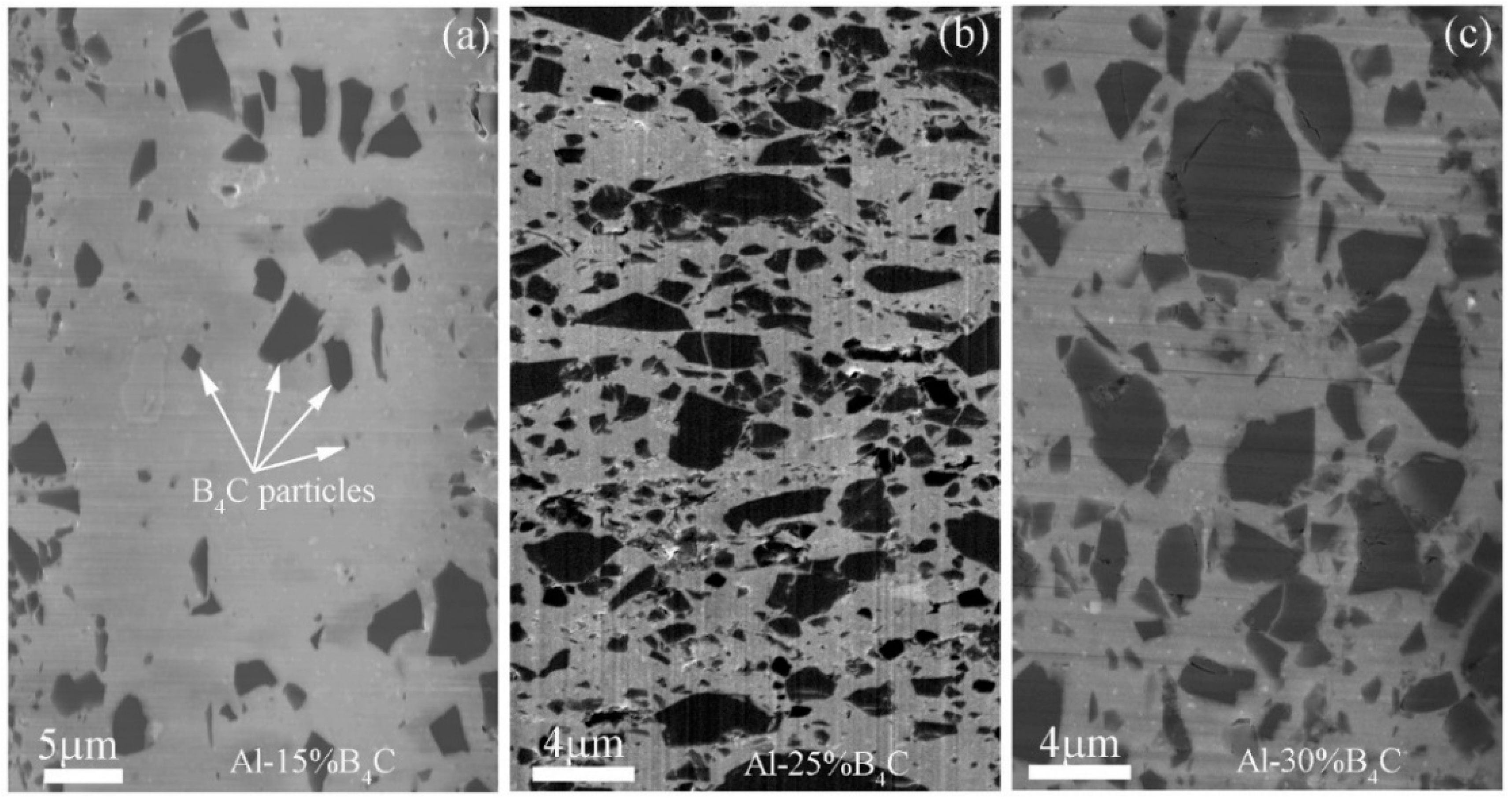
The surface morphology of the polished Al-15%B4C MMCs, Al-25%B4C MMCs and Al-30%B4C MMCs is shown in Figure 2a‒c, respectively. It can be seen that B4C particles indicated by white arrows homogeneously distribute in the Al matrix. The size of B4C particles, ranging from several hundred nanometers to several microns, is not uniform. The shape of the B4C particles is as a polygon. In addition, some pores and cracks can be found in the particles. A high concentration of damaged particles may have a critical impact on nucleation and propagation of cracks in the composites. However, Alizadeh [19] reported B4C particles uniformly dispersed in Al matrix and the pores in the composites could be negligible.
Appropriate dimension of dispersion B4C particles is one of the significant methods to optimize the neutron irradiation and corrosion properties of Al/B4C MMCs. Homogeneous distribution of particles is a prerequisite to enhance the related properties of the matrix alloy [20]. Therefore, the characteristics of B4C particles become very important. The statistical analysis results of B4C particles in Al/B4C MMCs are shown in Figure 3. The counting numbers is exceeded 150. The error bar is less than 1%. Area percentage of B4C particles is shown in Figure 3a, which indicates that the area of B4C particles mainly concentrates on the range from 0 to 0.5 μm2. The proportion of B4C particle size ranged from 0 to 0.5 μm2 in the Al-15%B4C, Al-25%B4C and Al-30%B4C MMCs are 64.29%, 86.99% and 76.86% of total statistical results, respectively. In addition, according to the statistical results and SEM observation, there are also several large-sized B4C particles distributing in the Al matrix. The proportion of B4C particle size that is larger than 9.0 μm2 in the Al-15%B4C, Al-25%B4C and Al-30%B4C MMCs are about 2.86%, 1.33% and 4.0%, respectively.
The average area of B4C particles in the Al-15%B4C, Al-25%B4C and Al-30%B4C MMCs are about 1.396, 0.528 and 1.183 μm2, respectively. It clear that the average area of B4C particles in the Al-15%B4C MMCs is about three times that of the Al-25%B4C MMCs. In addition, the maximum area of B4C particles in the current test is 21.51 μm2, 68.42 μm2 and 35.48 μm2 in the Al-15%B4C, Al-25%B4C and Al-30%B4C MMCs, respectively.
The bright field TEM image of the Al-30% B4C MMCs is shown in Figure 4a. The Al grains and B4C particles can be observed. Large amount of dislocations distribute in Al matrix. Meanwhile, twin structures can be observed in B4C particles as denoted by dark arrows. Li [21] also reported that the deformation twins were found in boron carbide particles within a nanostructured Al 5083/B4C MMCs. Heian [22] researched both of the milled and unmilled B4C samples and observed numerous nanometric twins in the micro-size grains. High angle annual dark field scanning transmission electron microscopy (HAADF-STEM) image in Figure 4b shows not only B4C particles as denoted by dark arrows but also alloy precipitates with bright color as denoted by white arrows. The grain size of the Al matrix is relatively homogeneous. However, from a more microscopic point of view, some grains show that they are round shape, while others show ellipse or lath-shaped. Similar phenomena could be found in the literature [23].
The size of alloy precipitates ranges from few tens of nanometers to several hundred nanometers. The grain boundaries of Al matrix can be obviously observed. Figure 4c,d are the HAADF-STEM images of the precipitates in the Al-30%B4C MMCs. The shape of the alloy precipitates shows an elliptic geometry. The element mapping results of Cr K, Si K, Cu K, Al K and Fe K are shown in Figure 4e–i, respectively. The elemental Cu, Cr, Fe and Si are found to be bright in the region of alloy precipitates. At the same time, elemental Al displays a shadow. The elemental mapping results show that the precipitates are the alloying of elemental Cu, Cr, Fe and Si, not including elemental Al.
In order to confirm that the nano-sized particles with dark color in HAADF-STEM images are the B4C particles, the electron energy loss spectroscopy (EELS) is used to analyze the elements. Two particles with approximately 100 nm are distributed in the Al-15% B4C MMCs matrix as shown in Figure 5a. The green box named “Spectrum Image” symbolizes the EELS map scanning region of elemental boron, while the yellow box named “Spatial Drift” is set to achieve the range migration correction accurately by choosing a black particle as reference point during the EELS mapping process. The B k and C k peaks are detected in the black particle as shown in Figure 5b. Therefore, it indicates that the effective detection region is composed by B and C elements. The mapping result of elemental boron in the dark particle is shown in Figure 5c, which indicates that the distribution of boron element is in good agreement with the morphology contour of the chosen black particle. The same experiment results were also obtained in the Al-25% B4C and Al-30% B4C MMCs samples. In addition, it is worth noting that the elemental boron cannot be detected in the Al gains at the precision scope of the EELS technology. However, in the present work, there is still a doubt that whether a few B or C atoms can diffuse into interstitial void of Al grains. The experimental results above suggest a way to calculate the distribution of boron element in Al/B4C MMCs, by figuring out the distribution of B4C particles in aluminum matrix.
Figure 6a is a bright field TEM image with low magnification showing the microstructure of Al grain and B4C particle. A pore with approximately 1 μm size can be observed at the boundary of Al grain and B4C particle. Figure 6b is high magnification of crystal boundary between Al matrix and B4C particle and Figure 6c is a high resolution TEM (HRTEM) image of their crystal boundary. The crystal lattice of Al grain and B4C particle can be observed. The crystal structure of Al grain and B4C phase are belong to face-centered cubic (FCC) and hexagonal close packed (HCP) lattice, respectively. The lattice parameter of B4C phase is a = 0.56003 nm, c = 1.2086 nm, and α = 90°, β = 90°, γ = 120°. The crystal plane distance dB4C(021) of B4C phase is equal to 0.238 nm. The distance of {111} crystal planes of Al phase (dAl(111)) is 0.234 nm. When the (021) crystal plane of B4C phase and (111) crystal plane of Al phase grow together, the lattice mismatch is approximately 1.68% and calculated as the following equation:
where, δ is the lattice mismatch. The calculation suggests that (021) crystal plane of B4C phase and (111) crystal plane of Al phase located in the interface are in parallel relationship closely, which is shown in Figure 6c.
δ = (dB4C(021) − dAl(111))/dB4C(021)
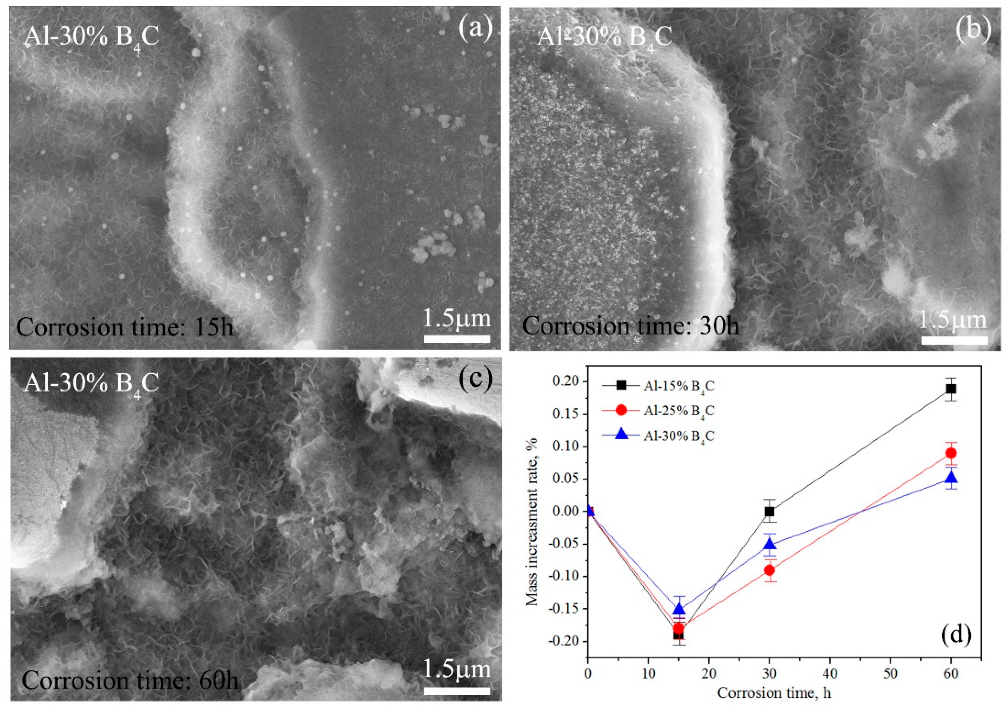
Figure 7 shows the SEM images showing the surface morphology of Al-30%B4C MMCs corroded for (a) 15 h, (b) 30 h and (c) 60 h in an aqueous solution with 5000 ppm boric acid at 100 °C and atmospheric pressure. Some flocculent oxide and pit etching are observed in the sample surface. The longer the corrosion time is, the more the amount of flocculent oxide and pit etching. The values of the mass increment rate after certain corrosion times are listed in Table 2. The relationship between the mass increment rate and corrosion time is shown in Figure 7d. It can be seen that the mass increment rate is first decreased with increasing corrosion time and then increased. The negative mass increment rate at 0–15 h corrosion time means that the mass of Al/B4C MMCs sample is decreased in that time period. During the procedure of sample corrosion, the oxide such as Al2O3 will be generated and also be simultaneously dissolved by boric acid. In the initial stage, the dissolution rate of corrosion products is larger than generation rate. Therefore, the sample mass is decreased and the mass increment rate occurs the negative. When the generation rate is larger than the dissolution rate, the mass increment rate will be changed to positive value and shows an increment trend. The reason should be due to the rapid oxidation of aluminum matrix, which is also used to explain that the mass increment rate of Al-15%B4C MMCs is largest at 15–60 h corrosion time because of the maximal aluminum content in these three kinds of Al/B4C MMCs. The mass increment is Δm (Al-30%B4C) < Δm (Al-25%B4C) < Δm (Al-15%B4C). However, more detailed corrosion properties and behaviors will be investigated in future work.
4. Conclusions
The microstructure of three kinds of Al/B4C MMCs used as neutron absorbers in both dry storage casks and wet storage pools of spent nuclear fuel were analyzed by SEM and TEM. A polishing method of focused Ga+ ion beam was provided to obtain an ideal sample surface with very low roughness, which was used to statistically analyze the distribution characteristics and size factor of B4C particles in the aluminum matrix. The corrosion properties and corresponding mechanism of Al/B4C MMCs were investigated in an aqueous solution with 5000 ppm boric acid at 100 °C and atmospheric pressure. The main conclusions could be made as followings:
- (1)
- The size of B4C particles ranging from several hundred nanometers to several microns were not uniform. The statistical results showed that the area of B4C particles mainly ranged from 0 to 0.5 μm2, which was the proportion of 64.29%, 86.99% and 76.86% of total statistical results for the Al-15%B4C, Al-25%B4C and Al-30%B4C MMCs, respectively. The average area of B4C particles in the Al-15%B4C, Al-25%B4C and Al-30%B4C MMCs were about 1.396 μm2, 0.528 μm2 and 1.183 μm2, respectively.
- (2)
- The nanoscale precipitates were analyzed by the element mappings in STEM mode and EELS mode, which included elliptic alloy precipitates with elemental Cu, Cr, Fe and Si, except for Al, and B4C nanoparticles with polygonal shape. The interface characteristics showed that the (021) crystal plane of B4C particle and (111) crystal plane of Al matrix grew together. The lattice mismatch was approximately 1.68%.
- (3)
- A large amount of flocculent oxide and pit etching were formed in the sample surface after chemical corrosion. The mass increment rate was first decreased with increasing corrosion time and then increased. When the corrosion time was larger than 15 h, the mass increment was Δm (Al-30%B4C) < Δm (Al-25%B4C) < Δm (Al-15%B4C).
Acknowledgments
The work was supported by the Natural Science Foundation of Fujian Province of China, through Project 2015J01021, by National major scientific research equipment development of China, through Grant No. 11227804, and by Shanghai Branch Company of China Nuclear Power Technology Research Institute through Grant No. XDHT2012430A.
Author Contributions
Guang Ran conceived and designed the experiments; Jianxin Lin performed the experiments and wrote the manuscript under the supervision of Guang Ran. Chao Ye obtained SEM images. All authors contributed to the scientific discussion of the results and reviewed the manuscript.
Conflicts of Interest
The authors declare no conflicts of interest.
References
- Nuclear Regulatory Commission. Spent Fuel Storage in Pools and Dry Casks Key Points and Questions & Answers. Available online: https://www.nrc.gov/waste/spent-fuel-storage/faqs.html (accessed on 14 November 2017).
- Lakosi, L.; Nguyen, C.T. Gamma and fast neutron radiation monitoring inside spent reactor fuel assemblies. Nucl. Instrum. Methods Phys. Res. B 2007, 580, 788–791. [Google Scholar] [CrossRef]
- Jostsons, A.; Dubose, C.K.H. Microstructure of boron carbide after fast neutron irradiation. J. Nucl. Mater. 1972, 44, 91–95. [Google Scholar] [CrossRef]
- Stoto, T.; Ardonceau, J.; Zuppiroli, L.; Castiglioni, M. Behaviour of implanted helium in boron carbide in the temperature range 750 to 1720° C. Radiat. Eff. 1987, 105, 17–30. [Google Scholar] [CrossRef]
- Zhang, F.; Wang, X.; Wierschke, J.B.; Wang, L. Helium bubble evolution in ion irradiated Al/B4C metal metrix composite. Scr. Mater. 2015, 109, 28–33. [Google Scholar] [CrossRef]
- Lai, J.; Zhang, Z.; Chen, X.G. The thermal stability of mechanical properties of Al–B4C composites alloyed with Sc and Zr at elevated temperatures. Mater. Sci. Eng. A 2012, 532, 462–470. [Google Scholar] [CrossRef]
- Hollenberg, G.W.; Cummings, W.V. Effect of fast neutron irradiation on the structure of boron carbide. J. Am. Ceram. Soc. 1977, 60, 520–525. [Google Scholar] [CrossRef]
- Takako, D.; Yoshiaki, T.; Naoaki, A.; Shoji, O.; Manabu, S.; Yuko, M. Neutron irradiation effects on 11B4C and recovery by annealing. J. Ceram. Soc. Jpn. 2007, 115, 551–555. [Google Scholar]
- Ashbee, K.H.G.; Dubose, C.K.H. Dislocation nodes in boron carbide, with special reference to non-stoichiometry. Acta Metall. 1972, 20, 241–245. [Google Scholar] [CrossRef]
- Gosset, D.; Miro, S.; Doriot, S.; Victor, G.; Motte, V. Evidence of amorphisation of B 4 C boron carbide under slow, heavy ion irradiation. Nucl. Instrum. Methods Phys. Res. 2015, 365, 300–304. [Google Scholar] [CrossRef]
- Luo, Z.; Song, Y.; Zhang, S.; Miller, D.J. Interfacial microstructure in a B4C/Al composite fabricated by pressureless infiltration. Metall. Mater. Trans. A 2012, 43, 281–293. [Google Scholar] [CrossRef]
- Ibrahim, M.F.; Ammar, H.R.; Samuel, A.M.; Soliman, M.S.; Almajid, A.; Samuel, F.H. Mechanical properties and fracture of Al-15 vol.-% B4C based metal matrix composites. Int. J. Cast Met. Res. 2014, 27, 7–14. [Google Scholar] [CrossRef]
- Shorowordi, K.M.; Laoui, T.; Haseeb, A.S.; Celis, J.P.; Froyen, L. Microstructure and interface characteristics of B4C, SiC and Al2O3 reinforced Al matrix composites: A comparative study. J. Mater. Process. Technol. 2003, 142, 738–743. [Google Scholar] [CrossRef]
- Ye, J.; He, J.; Schoenung, J.M. Cryomilling for the Fabrication of a Particulate B4C Reinforced Al Nanocomposite: Part I. Effects of Process Conditions on Structure. Metall. Mater. Trans. A 2005, 37, 3099–3109. [Google Scholar] [CrossRef]
- Zhang, P.; Li, Y.; Wang, W.; Gao, Z.; Wang, B. The design, fabrication and properties of B4C/Al neutron absorbers. J. Nucl. Mater. 2013, 437, 350–358. [Google Scholar] [CrossRef]
- Alizadeh, M.; Alizadeh, M.; Amini, R. Structural and mechanical properties of Al/B4C composites fabricated by wet attrition milling and hot extrusion. J. Mater. Sci. Technol. 2013, 29, 725–730. [Google Scholar] [CrossRef]
- Viala, J.C.; Bouix, J.; Gonzalez, G.; Esnouf, C. Chemical reactivity of aluminium with boron carbide. J. Mater. Sci. 1997, 32, 4559–4573. [Google Scholar] [CrossRef]
- Zaykova-Feldman, L.; Moore, T.M. The total release method for FIB in-situ TEM sample preparation. Microsc. Microanal. 2005, 11 (Suppl. 2), 848–849. [Google Scholar] [CrossRef]
- Alizadeh, M. Comparison of nanostructured Al/B4C composite produced by ARB and Al/B4C composite produced by RRB process. Mater. Sci. Eng. A 2010, 528, 578–582. [Google Scholar] [CrossRef]
- Ran, G.; Zhou, J.; Wang, Q.G. The effect of hot isostatic pressing on the microstructure and tensile properties of an unmodified A356-T6 cast aluminum alloy. J. Alloys Compd. 2006, 421, 80–86. [Google Scholar] [CrossRef]
- Li, Y.; Zhao, Y.H.; Liu, W.; Zhang, Z.H.; Vogt, R.G.; Lavernia, E.J.; Schoenung, J.M. Deformation twinning in boron carbide particles within nanostructured Al 5083/B4C metal matrix composites. Philos. Mag. 2010, 90, 783–792. [Google Scholar] [CrossRef]
- Heian, E.M.; Khalsa, S.K.; Lee, J.W.; Munir, Z.A.; Yamamoto, T.; Ohyanagi, M. Synthesis of Dense, High-Defect-Concentration B4C through Mechanical Activation and Field-Assisted Combustion. J. Am. Ceram. Soc. 2004, 87, 779–783. [Google Scholar] [CrossRef]
- Ye, J.; Lee, Z.; Ahn, B.; Nutt, S.R.; He, J.; Schoenung, J.M. Cryomilling for the fabrication of a particulate B4C reinforced Al nanocomposite: Part II. Mechanisms for microstructural evolution. Metall. Mater. Trans. A 2006, 37, 3111–3117. [Google Scholar] [CrossRef]
Figure 1.
(a,c) SEM images showing the surface morphology of Al/B4C MMCs polished by the conventional metallographic method and focused ion beam technique, respectively; (b) The sketch of sample surface polished by focused ion beam.
Figure 1.
(a,c) SEM images showing the surface morphology of Al/B4C MMCs polished by the conventional metallographic method and focused ion beam technique, respectively; (b) The sketch of sample surface polished by focused ion beam.
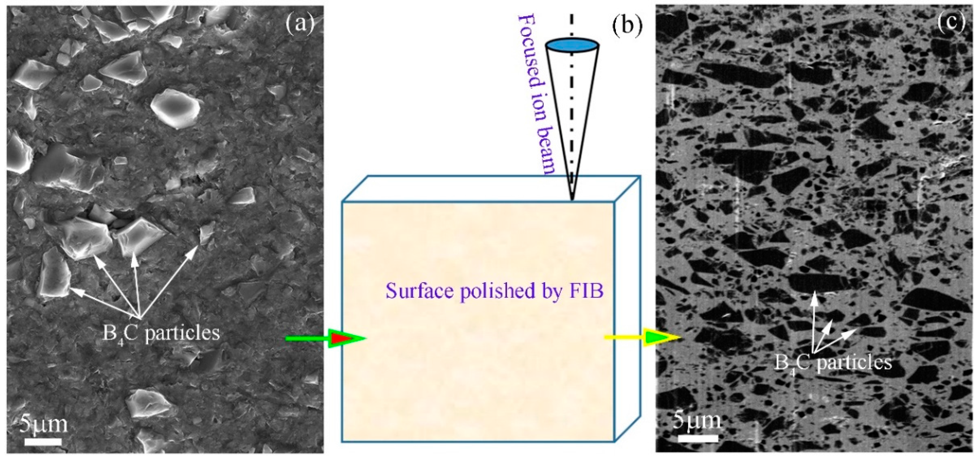
Figure 2.
SEM images showing the microstructures and morphology of (a) Al-15%B4C; (b) Al-25%B4C and (c) Al-30%B4C MMCs.
Figure 2.
SEM images showing the microstructures and morphology of (a) Al-15%B4C; (b) Al-25%B4C and (c) Al-30%B4C MMCs.

Figure 3.
Statistical analysis results of the B4C particles in Al/B4C MMCs, (a) Area percentage and (b) Average area of B4C particles.
Figure 3.
Statistical analysis results of the B4C particles in Al/B4C MMCs, (a) Area percentage and (b) Average area of B4C particles.
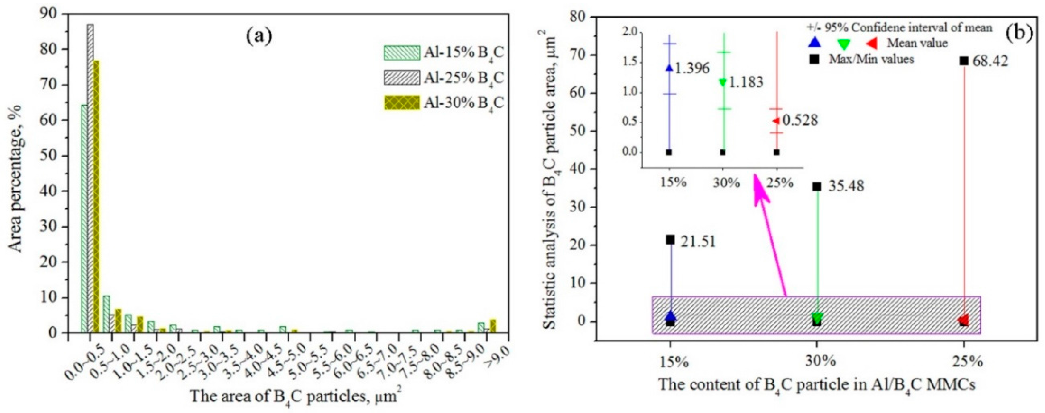
Figure 4.
(a) Bright field TEM image and (b) Low magnification high angle annual dark field scanning transmission electron microscopy (HAADF-STEM) image of Al-30% B4C MMCs; (c,d) HAADF-STEM images showing the precipitates in Al matrix; element mappings of (e) Cr K, (f) Si K, (g) Cu K, (h) Al K and (i) Fe K.
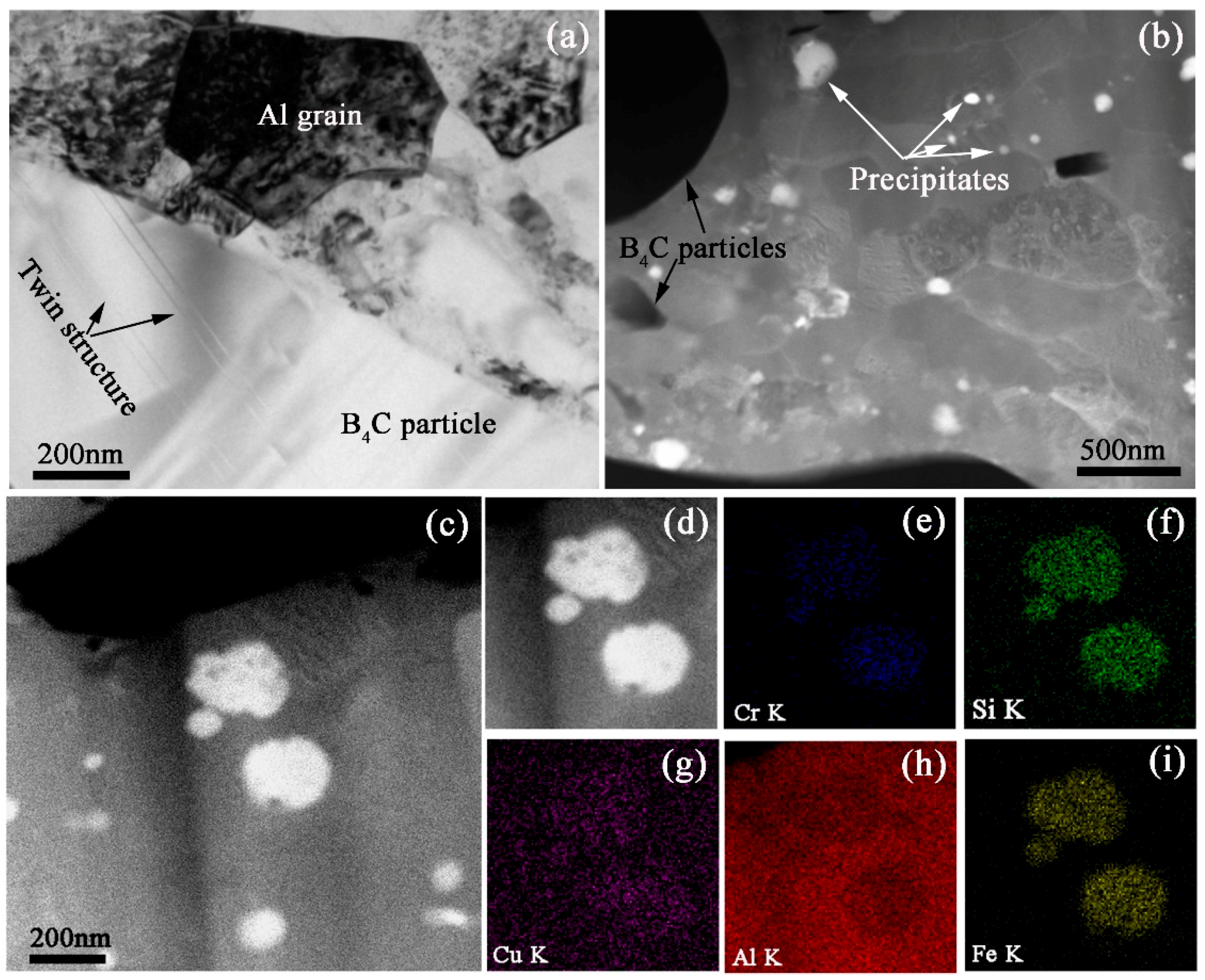
Figure 5.
(a) HAADF-STEM image showing the morphology of nano-sized B4C particles; (b) electron energy loss spectroscopy (EELS) spectrum; (c) EELS mapping result of boron element in the selected dark particle.
Figure 5.
(a) HAADF-STEM image showing the morphology of nano-sized B4C particles; (b) electron energy loss spectroscopy (EELS) spectrum; (c) EELS mapping result of boron element in the selected dark particle.
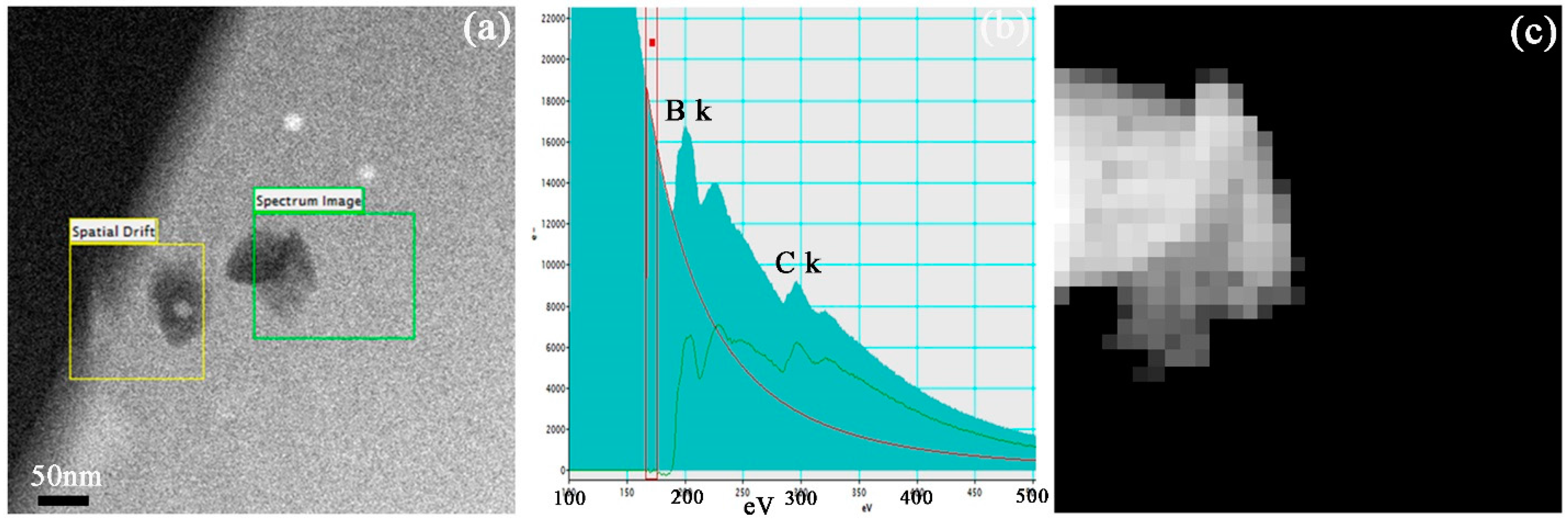
Figure 6.
(a) Bright field TEM image of Al-30%B4C MMCs; (b) High magnification of crystal boundary between Al matrix and B4C particle; (c) high resolution TEM (HRTEM) image.
Figure 6.
(a) Bright field TEM image of Al-30%B4C MMCs; (b) High magnification of crystal boundary between Al matrix and B4C particle; (c) high resolution TEM (HRTEM) image.
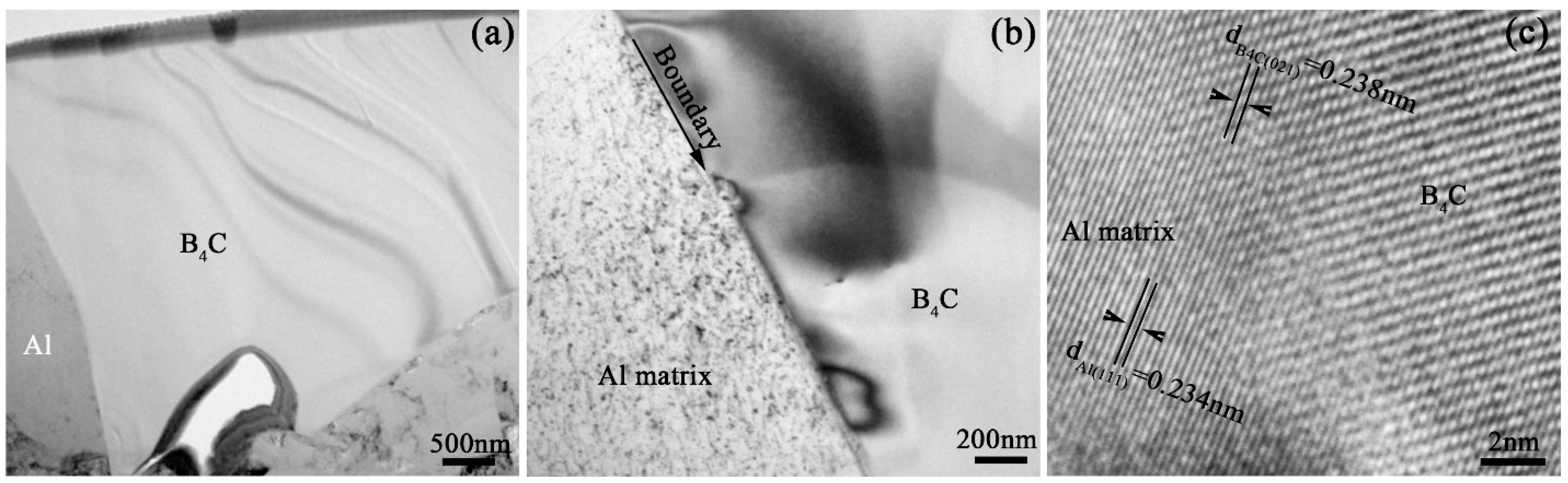
Figure 7.
SEM images showing the surface morphology of Al-30%B4C MMCs corroded for (a) 15 h, (b) 30 h and (c) 60 h at 1000 ppm boric acid solution at 100 °C and atmospheric pressure; (d) The mass incensement rate vs. corrosion time of three kinds of Al/B4C MMCs.
Figure 7.
SEM images showing the surface morphology of Al-30%B4C MMCs corroded for (a) 15 h, (b) 30 h and (c) 60 h at 1000 ppm boric acid solution at 100 °C and atmospheric pressure; (d) The mass incensement rate vs. corrosion time of three kinds of Al/B4C MMCs.


Table 1.
Chemical compositions of trace elements in three kinds of Al/B4C MMCs (wt %).
| Elements | Ba | Cr | Cu | Fe | Mg | Mn | Pb | Si | Ti | Zn | Zr |
|---|---|---|---|---|---|---|---|---|---|---|---|
| Al-15%B4C | 0.00021 | 0.1213 | 0.1248 | 0.9415 | 0.2135 | 0.0904 | 0.1042 | 0.3560 | 0.0115 | 0.0342 | 0.0204 |
| Al-25%B4C | 0.00031 | 0.1054 | 0.1084 | 0.3967 | 0.0674 | 0.0853 | 0.0911 | 0.2347 | 0.0101 | 0.0280 | 0.0042 |
| Al-30%B4C | 0.00067 | 0.0825 | 0.1034 | 0.2979 | 0.2225 | 0.0835 | 0.0851 | 0.2091 | 0.0095 | 0.0275 | 0.0041 |
Table 2.
Mass increment rate of Al/B4C MMCs during the corrosion (Δwt %).
| Materials | 0 h | 15 h | 30 h | 60 h |
|---|---|---|---|---|
| Al-15%B4C | 0 | −0.189 | 0.0 | 0.189 |
| Al-25%B4C | 0 | −0.180 | −0.090 | 0.090 |
| Al-30%B4C | 0 | −0.152 | −0.051 | 0.051 |
© 2017 by the authors. Licensee MDPI, Basel, Switzerland. This article is an open access article distributed under the terms and conditions of the Creative Commons Attribution (CC BY) license (http://creativecommons.org/licenses/by/4.0/).
Share and Cite
MDPI and ACS Style
Lin, J.; Ran, G.; Lei, P.; Ye, C.; Huang, S.; Zhao, S.; Li, N. Microstructure Analysis of Neutron Absorber Al/B4C Metal Matrix Composites. Metals 2017, 7, 567. https://doi.org/10.3390/met7120567
AMA Style
Lin J, Ran G, Lei P, Ye C, Huang S, Zhao S, Li N. Microstructure Analysis of Neutron Absorber Al/B4C Metal Matrix Composites. Metals. 2017; 7(12):567. https://doi.org/10.3390/met7120567
Chicago/Turabian StyleLin, Jianxin, Guang Ran, Penghui Lei, Chao Ye, Shilin Huang, Shangquan Zhao, and Ning Li. 2017. "Microstructure Analysis of Neutron Absorber Al/B4C Metal Matrix Composites" Metals 7, no. 12: 567. https://doi.org/10.3390/met7120567
Note that from the first issue of 2016, this journal uses article numbers instead of page numbers. See further details here.