Effect of Dynamic Reheating Induced by Weaving on the Microstructure of GTAW Weld Metal of 25% Cr Super Duplex Stainless Steel Weld Metal

1
Department of Hybrid Materials & Machining Technology, Graduate School of Convergence Science, Pusan National University, Busan 46241, Korea
2
Department of Material Science and Engineering, Pusan National University, Busandaehak-ro 63 beon-gil, Geumjeong-gu, Busan 46241, Korea
*
Author to whom correspondence should be addressed.
Metals 2017, 7(11), 490; https://doi.org/10.3390/met7110490
Submission received: 16 October 2017
/
Revised: 2 November 2017
/
Accepted: 6 November 2017
/
Published: 9 November 2017
Abstract
:The importance of the additional growth and/or transformation of the austenite phase that occurs in weld metals of super duplex stainless steel upon reheating is known. However, the effects have not been fully investigated, especially with respect to reheating induced by weaving during single-pass welding. In this work, bead-on-pipe gas tungsten arc welding (GTAW) was conducted on super duplex stainless steel to understand the effect of weaving on the microstructure of weld metal. Microstructural analysis, electron backscatter diffraction (EBSD), and focused ion beam transmission electron microscopy (FIB-TEM) were carried out to investigate the relationship between weaving and microstructural change. The weaving of GTAW produced a dynamic reheated area just before the weld bead during welding. It was revealed that extensive reheated weld existed even after one welding pass, and that the content of the austenite phase in the reheated area was higher than that in the non-reheated area, indicating the existence of a large quantity of intragranular austenite phase. In addition, the Cr2N content in the reheated area was lower than that in the non-reheated area. This reduction of Cr2N was closely related to the reheating resulting from weaving. TEM analysis revealed that Cr2N in the non-reheated area was dispersed following heating and transformed to secondary austenite.

1. Introduction
Super duplex stainless steel (SDSS) has been widely used in various fields, including process piping in offshore top-side structures and the chemical industry. SDSS has been shown to have excellent mechanical properties and chemical immunity toward several environments, especially chloride-bearing atmospheres [1,2,3,4,5,6]. However, it has also exhibited unexpected behaviors when treated thermally, such as during welding or heat treatment. To understand these behaviors, many researchers have studied the material from the time-temperature-transformation (TTT) or continuous cooling transformation (CCT) viewpoint, using simulation programs and isothermal heat treatments [7,8,9,10,11]. They emphasized the importance of precipitate and secondary austenite on the properties of SDSS. When SDSS is treated thermally, many adverse precipitates are introduced. These precipitates induce a depletion zone across the phase boundary between the precipitate and matrix, resulting in deleterious corrosion resistance owing to chemical inhomogeneity. During thermal treatment, a secondary austenite is produced from the growth of primary austenite, consuming Cr2N [12,13]. The secondary austenite contains lower levels of major chemical elements involved in resistance against pitting corrosion, compared with the primary austenite. Therefore, the secondary austenite can be considered as a pitting corrosion initiation point and an avoidable phase, because it has a lower pitting resistance equivalent number (PREN) than other phases [3]. However, Tan et al. [8] studied the relationship between base metal and heat treatment conditions, and found that the location of pitting initiation could not be specified clearly, since the location varied from the interface of ferrite/austenite to the interior of the austenite. It was reported that pitting corrosion was strongly related to the PREN value at each phase. Many researchers have highlighted the importance of Cr2N and secondary austenite. Pettersson et al. [14] studied the chromium nitride precipitation of UNS S32750 at different cooling rates. The pitting corrosion resistance of SDSS weld metal was closely correlated with precipitation during thermal treatments, such as heat treatment at various temperatures or welding [15,16]. A Cr depletion zone was reported at the Cr2N boundary [17,18], and the quantity of Cr2N in high-Mn DSS increased with high alloying, inducing corrosion resistance deterioration [19]. The corrosion potentials of austenite and ferrite phases under a corrosion environment were measured using electrochemical atomic force microscopy (EC-AFM) [20]. The isothermal nitride exhibited a higher Volta potential than the matrix. Heat treatment simulation tests with several DSS and SDSS showed that the formation of secondary austenite was strongly correlated with Cr2N precipitation. However, the mechanism was not clearly identified on the welds, because the studies focused on the base metal itself and the heat-affected zone (HAZ) [12,13,21]. In the study of Cr2N, the quantity of Cr2N increased with a decrease in the cooling rate [22]. Observations of microstructural change by heat treatment simulation with three kinds of welding consumables [23] and studies of the welding condition effect were conducted [24,25]. Nitrogen loss during autogenous multiple welds was observed [26]. The nitrogen content decreased as the number of welding passes increased. Therefore, a high proportion of ferrite remained at the final pass.
The welding process was not an isothermal phenomenon but a continuous cooling phenomenon. In addition, the weld bead was exposed to several types of heating cycles, such as reheating by multiple-pass welding. Even though many researchers have reported, directly or indirectly, the importance of reheating, such as during constant heat treatment at several temperatures or when changing the welding heat input, there has not been significant research into the influence of reheating from a microstructural and corrosion viewpoint, especially reheating by weaving techniques.
The weaving technique has been used in gas tungsten arc welding (GTAW) for offshore pipe welding applications [27]. It has not been reported to induce a kind of dynamic reheating on the immediately previous weld bead, even during single-pass welding, which was expected to have a marked effect on the microstructural changes that occur.
In this study, the effect of reheating produced in a single bead-on-pipe weld was investigated to determine the relationship between the weaving and the microstructure in terms of phase distribution over the weld metal.
2. Materials and Methods
2.1. Material
A UNS S32750 SDSS (Tubacex Tubos Inoxidables S.A.U, Amurrio (Alava), Spain)pipe with 168 mm in outer diameter and 7.11 mm in thickness was used as the base material, and a rod 2.4 mm in diameter (categorized as AWS 5.9 ER2594 (SANDVIK, Stockholm, Sweden)) was used as a welding wire. Chemical compositions and mechanical properties of the pipe and the wire are presented in Table 1 and Table 2, respectively. The chemical composition analysis of the welding wire showed that it contained more nickel (approximately 3 wt %) than the base material. The purpose of adding more nickel to the welding wire was to enhance austenite phase formation on the weld metal, which contained a low austenite fraction owing to rapid cooling. The major chemical elements of the base metal were Cr 25.5 wt %, Ni 6.65 wt %, and N 0.26 wt %. All PREN values were greater than 40, as shown in Table 1.
2.2. Welding Conditions
As shown in Figure 1, manual GTAW with a 2.4 mm diameter EWTh-2 (tungsten-2% thoria) non-consumable electrode and 99.99% argon shielding gas(Flow rate: 15L/min) was applied to the pipe material, using a welding rod of ER2594. Welding parameters were as shown in Table 3. The welding heat input was approximately 14.7 kJ/cm, and the bead width was 14.2 mm. GTAW was the main welding process used to join the pipe, and a weaving technique was employed. Bead-on-pipe single-pass welding was applied to understand the effect of weaving.
2.3. Macro-Micro Structural Analysis
The cross-section and half the surface of the weld bead were polished, and the overall bead appearance was investigated. This clearly showed the effect of weaving on the previous bead. The reason for the half-surface preparation was that the bead-on-pipe specimen was curved, as it was a quarter section of pipe. Therefore, the half-surface specimen was sufficient to provide the overall bead appearance, because the bead had symmetry in the center of the weld bead. The surface was polished using SiC sand paper and a mix of 1 μm diamond with 0.04 μm silica. Electrolytic etching method was applied in the ASTM E407 No. 96 (86 g NaOH + 50 mL water) solution at 6 V DC for 5~10 s to investigate the microstructural changes. Microstructural analysis was conducted using and Olympus BX-51M (Tokyo, Japan) on several regions, which showed different characteristics.
2.4. EBSD and TEM Investigation
The specimen was polished with emery paper and diamond paste (1 μm), and completed with silicate (0.04 μm) for electron backscatter diffraction (EBSD) investigation. EBSD analysis was conducted at two locations at the edge area and the center of weld, to understand the phase distribution induced by weaving.
To identify the precipitates on both the intergranular and intragranular areas, the specimens were extracted from three areas using a FEI Scios focused ion beam (FIB), followed by transmission electron microscopy (TEM) analysis with an FEI TALOS F200x field-emission transmission electron microscope (Hillsboro, OR, USA) and EDS at 200 kV, and a camera focal length of 840 mm for the diffraction patterns. Using the FEI TIA image analysis program (Hillsboro, OR, USA) and the ICDD card (Delaware County, PA, USA), the images were identified using the inter-planar distance (d) and the angle between the diffraction patterns. Additional image analysis (e.g., image length) was conducted using Media Cybernetics (Rockville, MD, USA) Image Plus Pro image analysis program.
3. Results
3.1. Macrostructural and Microstructural Analyses
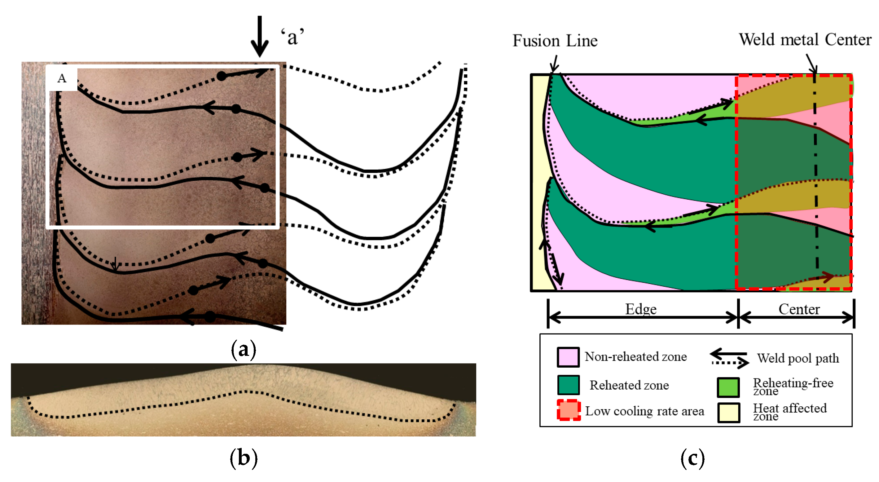
The outer appearance of the as-welded specimen and its bead filing-up sequences are shown in Figure 2a. A typical formation of a weld bead by weaving was recreated in a movie clip [28]. Stop motion was taken from the reference clip and a schematic diagram was redrawn, as shown in Figure 2b,c, respectively. The bead was formed by weaving of non-consumable electrode’s weaving and filler wire addition into the arc, filing-up beads. The weaving action was started from one side of the weld edge through the weld centerline and completed to the other side of the weld edge, melting and mixing both base metal and filler metal. This comprised one cycle of weaving, and it was repeated until one pass had been completed. As shown in Figure 3a, the molten pool path was superposed onto the top-view macro photograph to understand the relationship between the path and the microstructural change. The cross-section was analyzed at point “a” in Figure 3a. However, if the location was changed, the microstructure also changed greatly, because weaving dramatically changed the microstructure, as shown in Figure 3c. The categorized area is presented in detail in Figure 4.
Macroscopic photographs of the bead built-up sequences and reheating area produced by welding are shown Figure 2 and Figure 3. The bead was built-up by weaving, and was affected by the heat produced following the bead, as indicated by the slightly dark image shown in Figure 4. The cross-section toward the welding direction cannot show all the microstructural changes in the weld bead, because it was varied by cutting location. In this study, the surface that shows all the microstructural changes was examined as well, to better understand the overall microstructural changes resulting from reheating.
The area can be divided into two parts, as shown in Figure 3c and Figure 4. The area “B1” was the edge of the weld metal, “B2” was mid-way between the edge and the center, and the area “B2” was the center of the weld metal. The area B1 consisted of three regions: the reheated, non-reheated, and reheating-free regions, respectively. The width of the reheating-free zone varied, as shown in Figure 3a and Figure 4. The reheated area was the region where the previously welded metal had been completely solidified and then heated again by subsequent welding during the bead stacking process by weaving. The non-reheated area was the region where the weld metal was not heated, because it was located sufficiently far away from the following weld bead. The reheating-free zone was the region where the previous weld bead did not have enough time to solidify completely, owing to the quick return of the following bead. Therefore, the reheating phenomena did not occur in the bead, similar to the area that was never reheated.
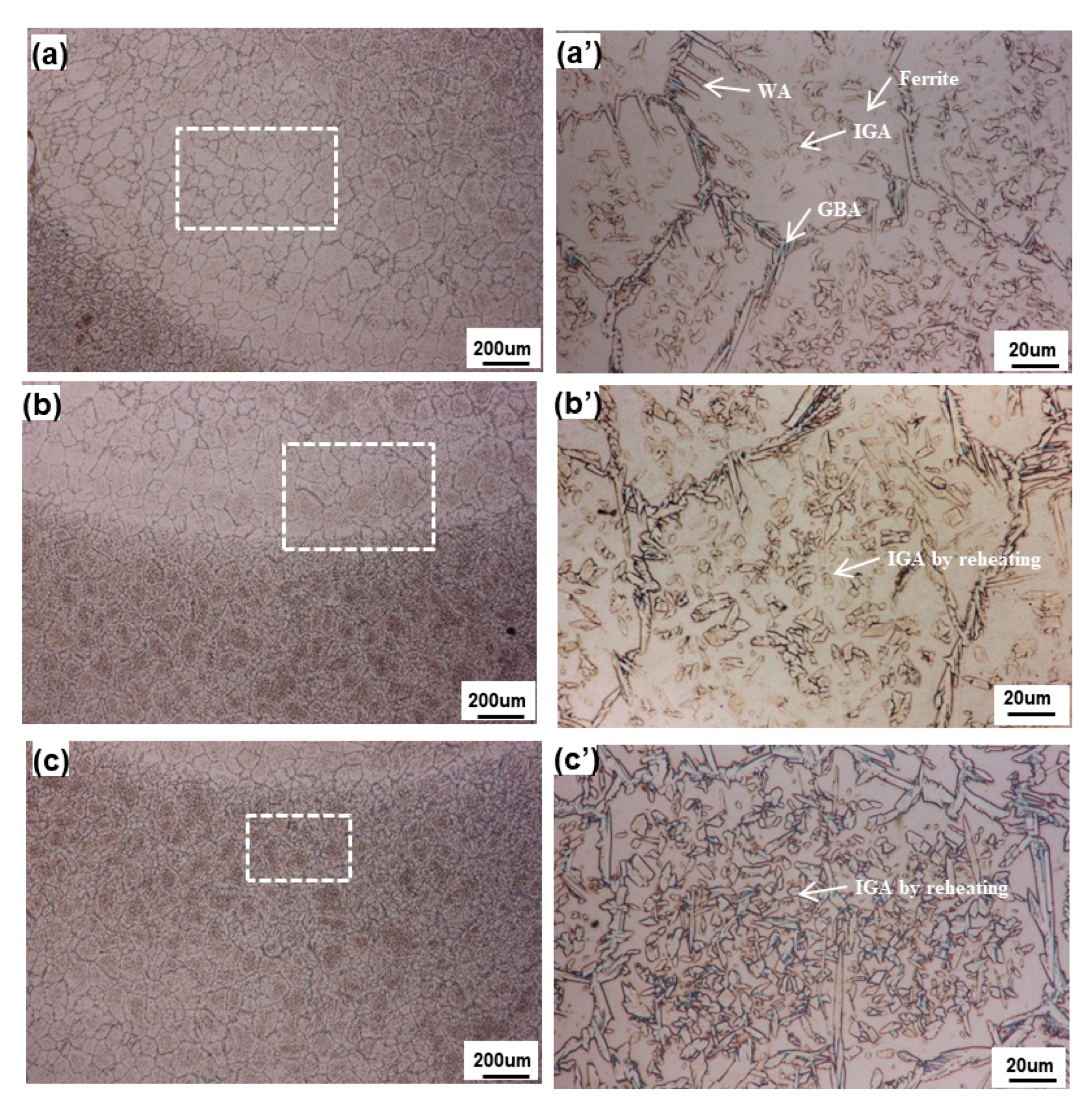
The microstructural analysis was conducted on the edge area. The ferrite phase, GBA (grain boundary austenite), WA (side-plate Widmanstätten austenite), and IGA (intragranular austenite) are shown in Figure 5a,a’. The non-reheated area contained a large proportion of ferrite phase and had a smaller grain size compared with the reheated area. The reheated area had a large grain size and contained IGA inside the grain, as shown in Figure 5c,c’. It was considered that reheating by weaving provided more time for grain growth and IGA phase precipitation. Therefore, the grain size was increased by reheating, and GBA/IGA were also increased, compared with the not-reheated area. As shown in Figure 5b,b’, the reheating-free zone showed a small quantity of IGA, similar to the non-reheated area, even though it was reheated.
The microstructure located between the edge and the center showed almost the same properties as the edge area (Figure 6), except for the width of each area. The widths of the reheated, non-reheated, and reheating-free zones (occurring at the edge, middle, and center, respectively), varied according to the degree of thermal effect induced during welding (Figure 4).
The microstructure at the center area resembled that seen in the edge analysis, except for the large grain size induced by the slower cooling rate (Figure 7). The microstructure of the center area can be split into the non-reheated weld metal, reheating-free zone, and reheated weld metal. As shown in Figure 7a,a’, the non-reheated area contained thicker GBA, a small quantity of WA, and a very small quantity of IGA. This area solidified after movement of the molten pool, which did not afford any reheating opportunity. Hence, a typical solidification of the weld metal is observed, as shown in Figure 5a,a’, except in the case of a larger grain size owing to the slow cooling rate. The grain size at the edge and the center were compared by EBSD analysis. The reheating-free zone, as investigated in other areas in this study, is shown in Figure 7b,b’. A very small quantity of IGA was found, which was unexpected. The area was located just below the fusion line and had been reheated intensely. However, the microstructure appeared to be almost the same as that of the non-reheated zone, with a similarly small quantity of IGA. Thus, it was found that there existed a reheating-free zone, even though this area had been reheated. This is perhaps because the area was heated again just after solidifying and/or while in still the liquid state, owing to the rapid movement of the molten pool by weaving. Therefore, the weld was not affected significantly by the additional heat, because it had not completely solidified and, hence, it absorbed the heat without presenting reheating phenomena. As shown in Figure 7c,c’, the weld metal was expected to be reheated after being completely solidified, which would result in a large quantity of IGA.
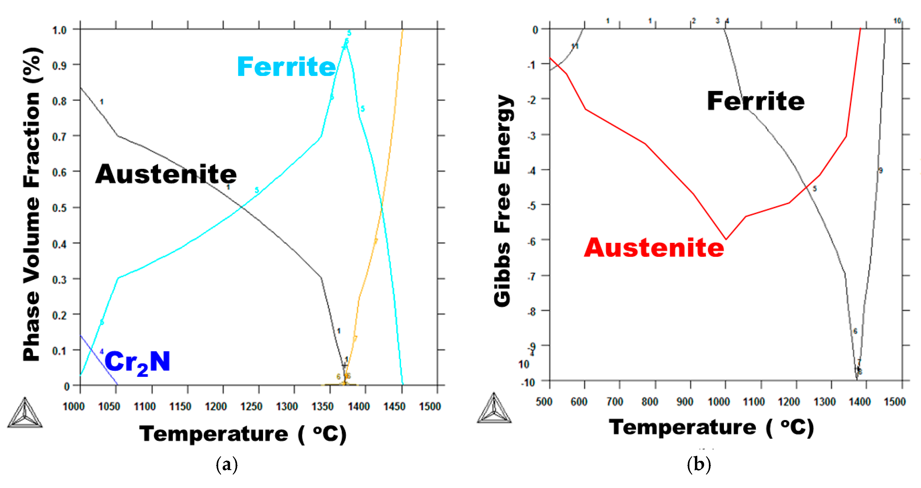
SDSS was solidified from liquid when it was welded. However, the cooling rate was so fast that it was difficult to obtain an equilibrium microstructure as in the base metal. Some of the nitrogen was absorbed into the austenite phase, which was precipitated during solidification. The remaining nitrogen was precipitated at the interior of the ferrite phase as Cr2N. Upon reheating, the phase tended to move toward a standard microstructure, such as 50% ferrite and 50% austenite. Therefore, some of the ferrite phase had to transform to austenite phase, consuming Cr2N. However, the Cr2N was so small that it was difficult to detect it by optical microstructural analysis. Its presence was confirmed later using EBSD and TEM analyses.
As shown by the microstructural analysis results, the fraction of austenite increased, and the size of grain also increased via growth of grains and restructuring among grains of similar direction.
Investigation of the non-reheated area showed that the weld metal contained a large proportion of ferrite phase, with a relatively small proportion of austenite phase, even though the austenite fraction in the equilibrium state was large. This was because rapid cooling did not allow the precipitation of austenite phase. However, if the non-reheated area was reheated, such as in the weaving technique or multi-pass welding, there was an opportunity to recover the equilibrium state, precipitating the austenite phase and simultaneously consuming Cr2N. The reheated area of the previous weld bead showed a typical coarse-grained HAZ (CGHAZ) in the base metal. However, there existed more IGA phase than in the non-reheated area, and some growth of GBA was also detected. This was called secondary austenite, owing to its different chemical composition. The reheating-free zone had equivalent characteristics to those of the non-reheated area, even though it was reheated. It was located near the inter-bead fusion zone.
3.2. EBSD Analysis
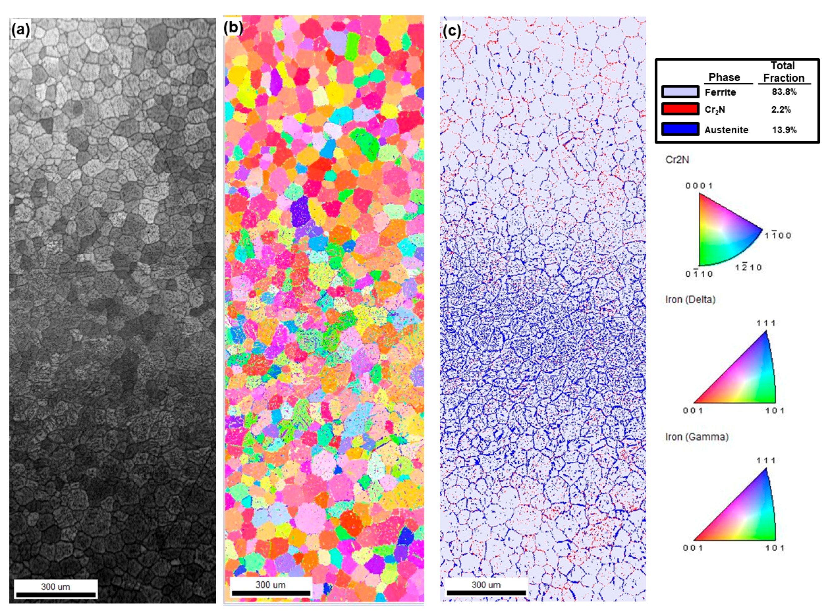
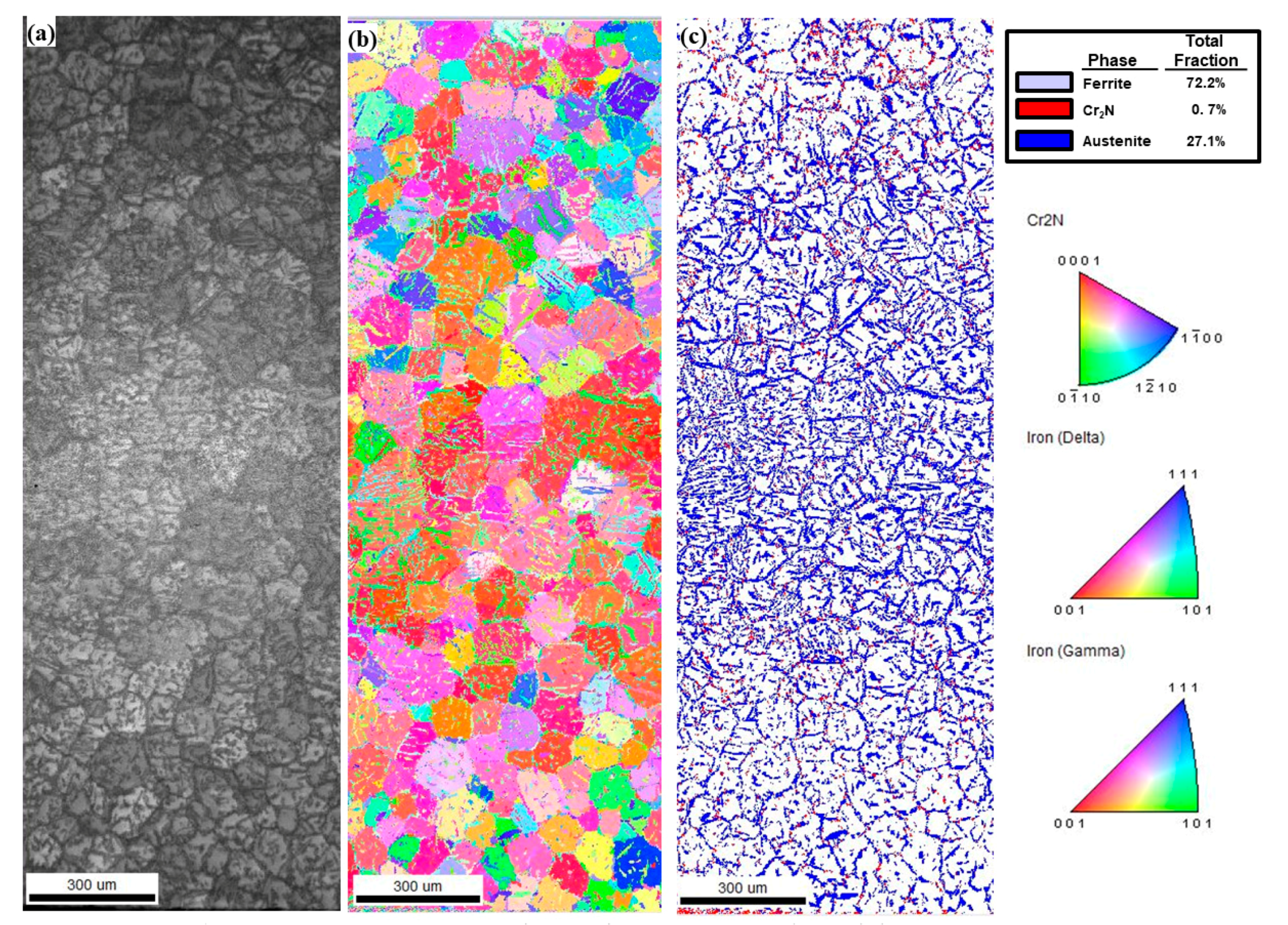
As shown by the microstructural analysis, there were phase distribution changes in the non-reheated and reheated areas indicated by the EBSD analysis results (Figure 8 and Figure 9). There were three major phases in the SDSS welds in this study, austenite, ferrite, and Cr2N, owing to rapid cooling. The distribution of phases revealed that the non-reheated area had a ferrite-dominant area with a high Cr2N proportion, while the reheated and multiply-reheated areas had a large proportion of austenite and small proportion of Cr2N.
The microstructural changes are summarized in Table 4. The austenite phase was increased and Cr2N was decreased by reheating. In addition, Cr2N dissolution induced austenite phase growth. The quantity of secondary austenite increased as Cr2N decreased.
4. Discussion
4.1. Phase Fraction at the Edge and the Center of Weld Metal
The austenite phase fraction at the edge area was found to be lower than that of the center area. This was likely because the cooling rate of the edge area was higher compared with that of the center area, as the molten pool was retained for longer in the center area. Therefore, the center area had more time to reach equilibrium status (Figure 10). As shown in Figure 10, the fraction of austenite phase increased as the temperature of weld metal decreased, whereas the ferrite phase showed the opposite tendency. However, the weld metal solidified so rapidly that it was almost impossible for it to obtain equilibrium status. It has been reported by many researchers that fast cooling induces a high volume fraction of ferrite phase, owing to the lack of austenite transformation time [12,28]. In Table 4, the edge austenite phase fraction was 13.9 vol %, while the center austenite phase fraction was 27.1 vol %.
4.2. Phase Fraction between Reheated Weld Metal and Non-Reheated Weld Metal
When the weld metal solidified quickly, all volume fractions of the phases were not in equilibrium. High volume fractions of the ferrite phase and Cr2N were found compared with the equilibrium phase. When the weld metal was reheated by any other means, the weld metal spontaneously transformed to obtain the equilibrium phase ratio, reducing the Gibbs free energy, as shown in Figure 10b. In particular, increment of the austenite phase requires a nitrogen resource from elsewhere, such as the Cr2N which exists at the boundary of the ferrite and austenite phases, as well as other locations.
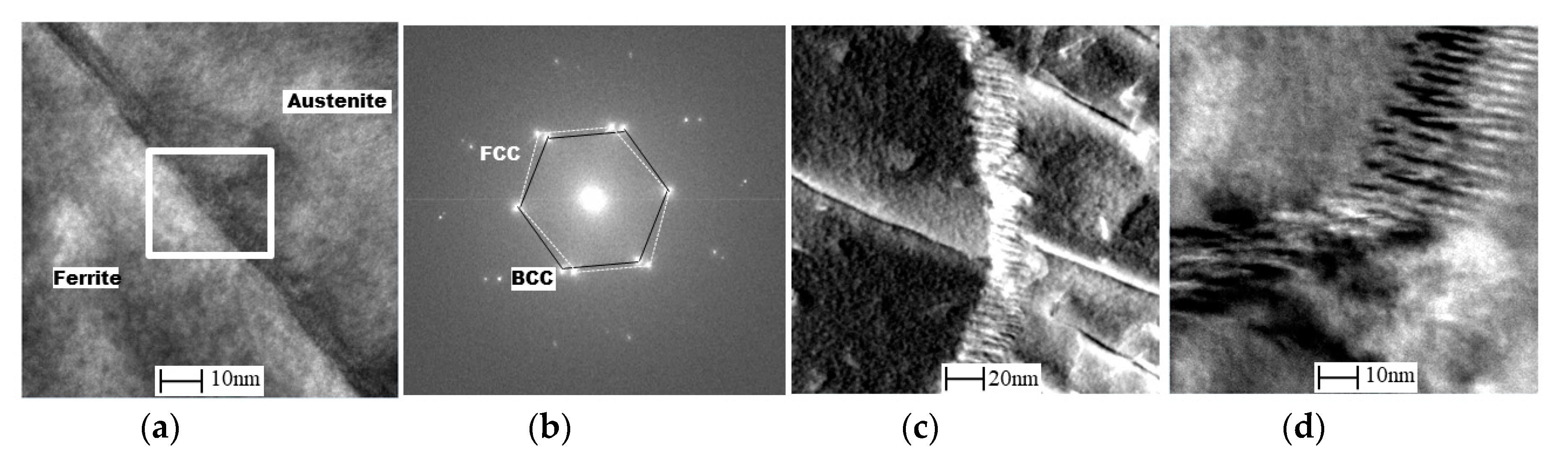
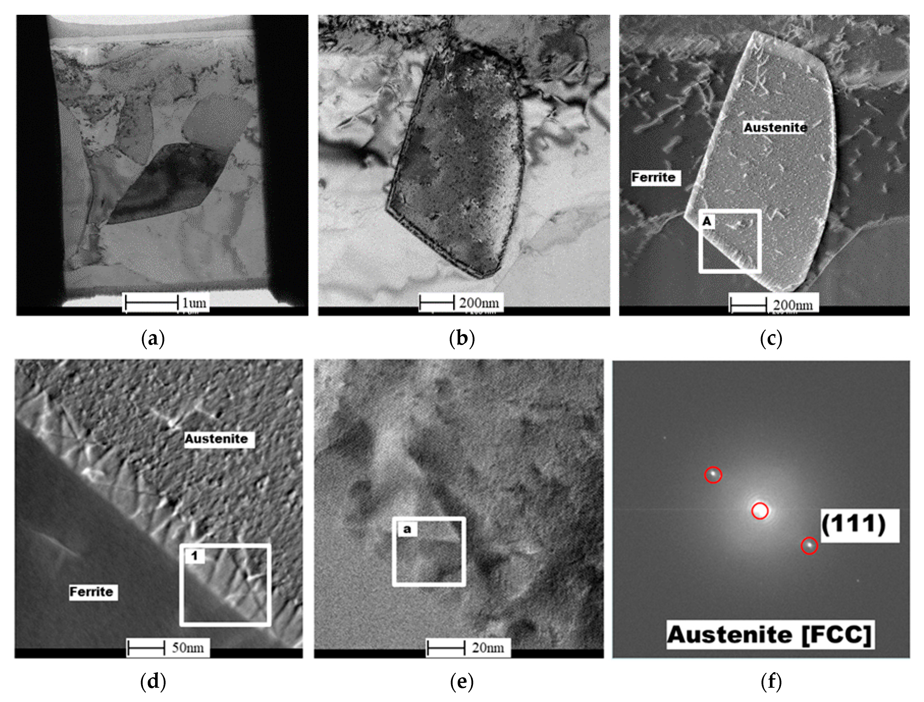
To verify the existence and the dissolution of Cr2N, FIB-TEM specimens were taken from both reheated and non-reheated areas of the weld metal edge area. The TEM results showed that Cr2N in the non-reheated area was located near the phase boundary and the inclusion, as shown in Figure 11. The inclusion consisted of Al oxide, and the precipitate was Cr2N, as determined by TEM energy dispersive X-ray (EDX) spectroscopy. Moreover, a precipitate was detected at the boundary of the ferrite/austenite, with a size of 5 nm, as shown in Figure 12. However, the X-ray pattern was not identified. Cr2N precipitates with other shapes were identified, as shown in Figure 12c,d. It was thought that the width of the precipitate was so thin that the X-ray pattern could not detect it. The depletion zone of Cr was not detected in this study, although other researchers have reported such a depletion zone under thermal heat treatment [17,18].
TEM photographs of the reheated area showed that there was no detectable precipitate at the boundary of ferrite/austenite (Figure 13). On the other hand, the austenite phase was surrounded by a certain band structure, the pattern of which indicated austenite, with a width of approximately 40 nm, as shown in Figure 13f. From these results, it was concluded that the band was produced by Cr2N dissolution as a result of reheating, consistent with previous reports [12,29].
4.3. Reheating-Free Zone
It was anticipated that a reheated area would be found wherever the weld metal had been reheated. Some areas, however, showed no noticeable reheating phenomena, even though the weld metal had definitely been reheated, as shown in Figure 4 and Figure 7c,c’. It was concluded that such areas had been reheated again just after solidification, and/or they retained liquid. For this reason, the areas remained reheating-free zones after completion of welding. These areas were narrower at the edge and wider at the center.
4.4. Chromium Nitride (Cr2N) Fraction between the Edge and the Center Weld Metal
The formation of Cr2N was induced by supersaturation of nitrogen in the ferrite phase during rapid cooling. The edge cooling rate was faster than that of the center, owing to the longer duration of the molten pool. Therefore, the edge had a high volume fraction of ferrite, while the center had a lower volume fraction. The higher the ferrite volume fraction of the weld metal, the more Cr2N was formed, because the nitrogen contained in the ferrite phase needs to expel it within a very short time [12,30].
5. Conclusions
GTA welding with an ER2594 welding rod was conducted using weaving, in order to investigate the effects of weaving on the microstructure of weld metal of 25Cr SDSS. The results of this research can be summarized as follows.
- Even though single-pass bead-on-pipe welding was carried out, there was a reheating phenomenon, called “dynamic reheating”. It was found that top-view investigation was a better method to recognize the entire dynamic reheating phenomena, compared with cross-section investigation.
- The center area had a comparatively low cooling rate, owing to the fact that the molten pool produced during welding remained for longer than in the edge area. It was found that the austenite phase fraction at the center was higher than that of the edge area, while the Cr2N content was lower at the center than in the edge area.
- A “reheating-free zone” was detected, even though this area was definitely reheated. Reheating phenomena had disappeared in this area, because it was at a very high temperature and/or was liquid, even though it was located in the reheated zone.
- The austenite phase volume fraction of reheated weld metal was higher than that of non-reheated weld metal, while the Cr2N volume fraction showed the opposite tendency. However, the Cr2N content of the reheated area decreased, because it had dissolved during the austenite phase transformation and/or growth as a result of reheating.
- From the TEM result, Cr2N was found to exist at the ferrite/austenite phase boundary of the non-reheated area, with 10 nm width. However, it was not detected at the phase boundary of the reheated area; instead, a 50-nm-wide band, consisting of secondary austenite, was found, as expected.
Acknowledgments
This work was supported by a National Research Foundation of Korea (NRF) grant funded by the Korean government (MSIP) (No. 2012R1A5A1048294).
Author Contributions
Hee-Joon Sung, Hye-Sung Na and Chung-Yun Kang conceived and designed the experiments; Hee-Joon Sung and Hye-Sung Na performed the experiments; Hee-Joon Sung, Hye-Sung Na and Chung-Yun Kang analyzed the data; Hee-Joon Sung wrote this paper.
Conflicts of Interest
The founding sponsors had no role in the design of the study; in the collection, analyses, or interpretation of data; in the writing of the manuscript, and in the decision to publish the results.
References
- Sedriks, A.J. Effects of alloy composition and microstructure on the passivity of stainless steels. Corrosion 1986, 42, 376. [Google Scholar] [CrossRef]
- Bernhardsson, S. Duplex Stainless Steels’91; Charles, J., Bernhardsson, S., Eds.; Les Editions de Physique: Beaune, France, 1991; Volume 1, p. 185. [Google Scholar]
- Nilsson, J.-O. Super duplex stainless steels. Mater. Sci. Technol. 1992, 8, 685–700. [Google Scholar] [CrossRef]
- Charles, J. Why and where duplex stainless steels. In Proceedings of the Duplex Stainless Steel ’97 International Conference & Expo, Maastricht, The Netherlands, 21–23 October 1997; pp. 29–42. [Google Scholar]
- Alvarez-Armas, I. Duplex stainless steels: Brief history and some recent alloys. Recent Pat. Mech. Eng. 2008, 1, 51–57. [Google Scholar] [CrossRef]
- Messer, B.; Wright, A.; Oprea, V. Duplex Stainless Steel Welding. Best Practices; Fluor Canada Ltd.: Calgary, AB, Canada, 2007; Volume 11, pp. 45–63. [Google Scholar]
- Calliari, I.; Bassani, P.; Brunelli, K.; Breda, M.; Ramous, E. Effect of continuous cooling on secondary phase precipitation in the super duplex stainless steel ZERON-100. J. Mater. Eng. Perform. 2013, 22, 3860–3866. [Google Scholar] [CrossRef]
- Tan, H.; Jiang, Y.; Deng, B.; Sun, T.; Xu, J.; Li, J. Effect of annealing temperature on the pitting corrosion resistance of SDSS UNS S32750. Mater. Charact. 2009, 60, 1049–1054. [Google Scholar] [CrossRef]
- Deng, B.; Jiang, Y.M.; Gao, J.; Li, J. Effect of annealing treatment on microstructure evolution and the associated corrosion behavior of a super-duplex stainless steel. J. Alloys Compd. 2010, 493, 461–464. [Google Scholar] [CrossRef]
- Cervo, R.; Ferro, P.; Tiziani, A. Annealing temperature effects on super duplex stainless steel UNS s32750 welded joints. I: Microstructure and partitioning of elements. J. Mater. Sci. 2010, 45, 4369–4377. [Google Scholar] [CrossRef]
- Chan, K.; Tjong, S. Effect of secondary phase precipitation on the corrosion behavior of duplex stainless steels. Materials 2014, 7, 5268–5304. [Google Scholar] [CrossRef] [PubMed]
- Ramirez, A.J.; Lippold, J.C.; Brandi, S.D. The relationship between chromium nitride and secondary austenite precipitation in duplex stainless steels. Met. Mater. Trans. Coruña 2003, 34, 1575–1597. [Google Scholar] [CrossRef]
- Zhang, Z.; Jing, H.; Xu, L.; Han, Y.; Gao, Z.; Zhao, L.; Zhang, J. Microstructural characterization and electron backscatter diffraction analysis across the welded interface of duplex stainless steel. Appl. Surf. Sci. 2017, 413, 327–343. [Google Scholar] [CrossRef]
- Pettersson, N.; Pettersson, R.F.A.; Wessman, S. Precipitation of chromium nitrides in the super duplex stainless steel 2507. Met. Mater. Trans. Coruña 2015, 46, 1062–1072. [Google Scholar] [CrossRef]
- Smiderle, J.; Pardal, J.M.; Tavares, S.S.M.; Vidal, A.C.N. Premature failure of superduplex stainless steel pipe by pitting in sea water environment. Fail. Anal. 2014, 46, 134–139. [Google Scholar] [CrossRef]
- Linton, V.M.; Laycock, N.J.; Thomsen, S.J.; Klumpers, A. Failure of a SDSS reaction vessel. Eng. Fail. Anal. 2004, 11, 243–256. [Google Scholar] [CrossRef]
- Kim, S.-T.; Lee, I.-S.; Kim, J.-S.; Jang, S.-H.; Park, Y.-S.; Kim, K.-T.; Kim, Y.-S. Investigation of the localized corrosion associated with phase transformation of tube-to-tube sheet welds of hyper duplex stainless steel in acidified chloride environments. Corros. Sci. 2012, 64, 164–173. [Google Scholar] [CrossRef]
- Zhang, S.; Jiang, Z.; Li, H.; Feng, H.; Zhang, B. Detection of susceptibility to intergranular corrosion of aged super austenitic stainless steel S32654 by a modified electrochemical potentiokinetic reactivation method. J. Alloys Compd. 2017, 695, 3083–3093. [Google Scholar] [CrossRef]
- Ha, H.; Kwon, H. Effects of Cr2N on the pitting corrosion of high nitrogen stainless steels. Electrochim. Acta 2007, 52, 2175–2180. [Google Scholar] [CrossRef]
- Eleonora Bettini, U.K.; Leygraf, C.; Pan, J. Study of corrosion behavior of a 2507 SDSS: Influence of quenched-in and isothermal nitrides. Int. J. Electrochem. Sci. 2014, 9, 61–80. [Google Scholar]
- Nilsson, J.O.; Wilson, A. Influence of isothermal phase transformations on toughness and pitting corrosion of super duplex stainless steel SAF 2507. Mater. Sci. Technol. 1993, 9, 545–554. [Google Scholar] [CrossRef]
- Liao, J. Nitride Precipitation in weld HAZs of a duplex stainless steel. ISIJ Int. 2001, 41, 460–467. [Google Scholar] [CrossRef]
- Nilsson, J.-O.; Huhtala, T.; Jonsson, P.; Karlsson, L.; Wilson, A. Structural stability of super duplex stainless weld metals and its dependence on tungsten and copper. Met. Mater. Trans. Coruña 1996, 27, 2196–2208. [Google Scholar] [CrossRef]
- Devendranath Ramkumar, K.; Mishra, D.; Ganesh Raj, B.; Vignesh, M.K.; Thiruvengatam, G.; Sudharshan, S.P.; Arivazhagan, N.; Sivashanmugam, N.; Rabel, A.M. Effect of optimal weld parameters in the microstructure and mechanical properties of autogeneous gas tungsten arc weldments of super-duplex stainless steel UNS S32750. Mater. Des. (1980–2015) 2015, 66, 356–365. [Google Scholar] [CrossRef]
- Eghlimi, A.; Shamanian, M.; Raeissi, K. Effect of current type on microstructure and corrosion resistance of super duplex stainless steel claddings produced by the gas tungsten arc welding process. Surf. Coat. Technol. 2014, 244, 45–51. [Google Scholar] [CrossRef]
- Hosseini, V.A.; Wessman, S.; Hurtig, K.; Karlsson, L. Nitrogen loss and effects on microstructure in multipass TIG welding of a SDSS. Mater. Des. 2016, 98, 88–97. [Google Scholar] [CrossRef]
- Kiesche, M.; Donath, V. TIG welding of root runs in the vertical position. Weld. Int. 1991, 5, 828–830. [Google Scholar] [CrossRef]
- Chul, S.J. Weld Camera YouTube. 27 June 2016. Available online: https://www.youtube.com/watch?v=3mpyWP9OKGo (accessed on 30 September 2017).
- Garzon, C.; Ramirez, A. Growth kinetics of secondary austenite in the welding microstructure of a UNS S32304 duplex stainless steel. Acta Mater. 2006, 54, 3321–3331. [Google Scholar] [CrossRef]
- Sieurin, H.; Sandström, R. Austenite reformation in the heat-affected zone of duplex stainless steel 2205. Mater. Sci. Eng. Coruña 2006, 418, 250–256. [Google Scholar] [CrossRef]
Figure 1.
Schematic diagram of bead-on-pipe welding.
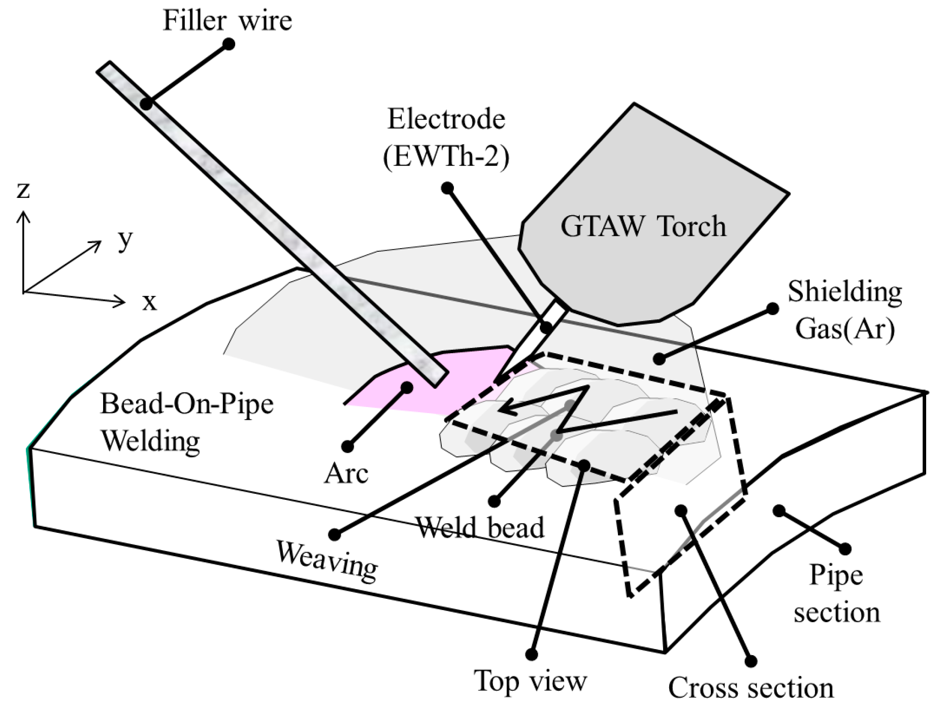
Figure 2.
Bead appearance and schematic diagram of molten pool movement by weaving: (a) bead appearance and molten pool path; (b) stop motion during welding from reference movie clip; and (c) schematic diagram of stop motion during welding.
Figure 2.
Bead appearance and schematic diagram of molten pool movement by weaving: (a) bead appearance and molten pool path; (b) stop motion during welding from reference movie clip; and (c) schematic diagram of stop motion during welding.
Figure 3.
Macro from top and cross-section and their classification: (a) top view of weld metal macro and molten pool path; (b) cross-section of weld metal from “a” direction; and (c) weld metal area classification of location “A” of Figure 3a.
Figure 3.
Macro from top and cross-section and their classification: (a) top view of weld metal macro and molten pool path; (b) cross-section of weld metal from “a” direction; and (c) weld metal area classification of location “A” of Figure 3a.

Figure 4.
Location of microstructure, EBSD, and TEM observations, and microstructural classification.
Figure 4.
Location of microstructure, EBSD, and TEM observations, and microstructural classification.
Figure 5.
Microstructural analysis at the edge of the weld metal location “B1” of Figure 4: (a,a’) non-reheated WM; (b,b’) reheating-free zone; and (c,c’) reheated WM (WA: Widmanstätten austenite, IGA: intragranular austenite, GBA: grain boundary austenite).
Figure 5.
Microstructural analysis at the edge of the weld metal location “B1” of Figure 4: (a,a’) non-reheated WM; (b,b’) reheating-free zone; and (c,c’) reheated WM (WA: Widmanstätten austenite, IGA: intragranular austenite, GBA: grain boundary austenite).

Figure 6.
Microstructural analysis at location “B2” of weld metal of Figure 4: (a,a’) non-reheated WM; (b,b’) reheating-free zone; and (c,c’) reheated WM.
Figure 6.
Microstructural analysis at location “B2” of weld metal of Figure 4: (a,a’) non-reheated WM; (b,b’) reheating-free zone; and (c,c’) reheated WM.
Figure 7.
Microstructural analysis at the center of WM of location “B3” of Figure 4: (a,a’) non-reheated WM; (b,b’) reheating-free zone; and (c,c’) reheated WM.
Figure 7.
Microstructural analysis at the center of WM of location “B3” of Figure 4: (a,a’) non-reheated WM; (b,b’) reheating-free zone; and (c,c’) reheated WM.
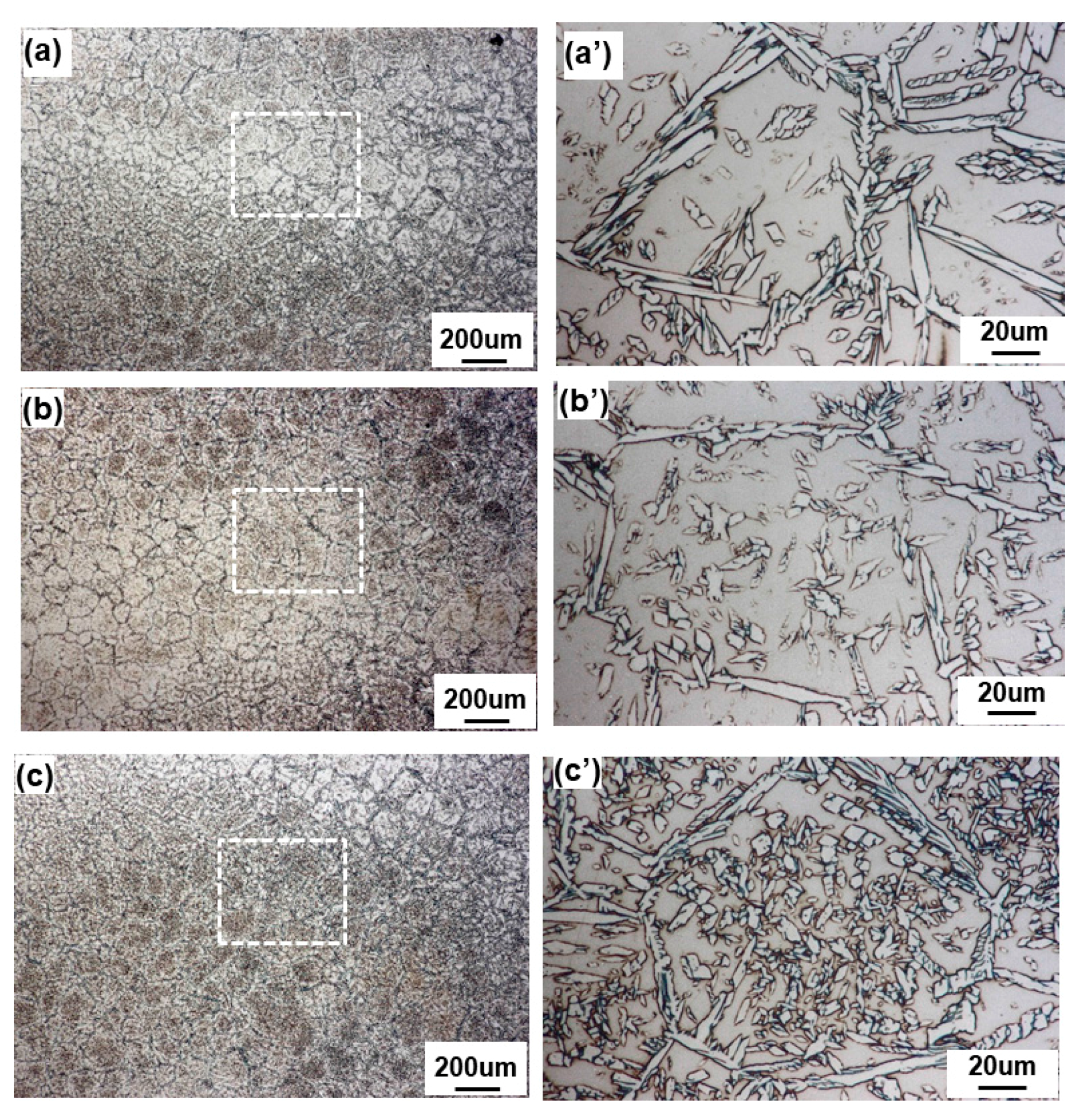
Figure 8.
EBSD result at the edge of the weld: (a) IQ image; (b) inverse for figure; and (c) phase map.
Figure 8.
EBSD result at the edge of the weld: (a) IQ image; (b) inverse for figure; and (c) phase map.

Figure 9.
EBSD result at the center of the weld: (a) IQ image; (b) inverse for figure; and (c) phase map.
Figure 9.
EBSD result at the center of the weld: (a) IQ image; (b) inverse for figure; and (c) phase map.

Figure 10.
Phase volume fraction and Gibbs free energy diagram versus temperature calculated by Thermo-Calc TM: (a) phase volume fraction; and (b) Gibbs free energy.
Figure 10.
Phase volume fraction and Gibbs free energy diagram versus temperature calculated by Thermo-Calc TM: (a) phase volume fraction; and (b) Gibbs free energy.

Figure 11.
TEM analysis result at the non-reheated area: (a) FIB-TEM; (b) phase boundary; (c) inclusion and precipitate at location “A” of Figure 11b; (d) X-ray pattern at location “1” and “2” of Figure 11c; and (e) TEM EDX mapping at Figure 11c.
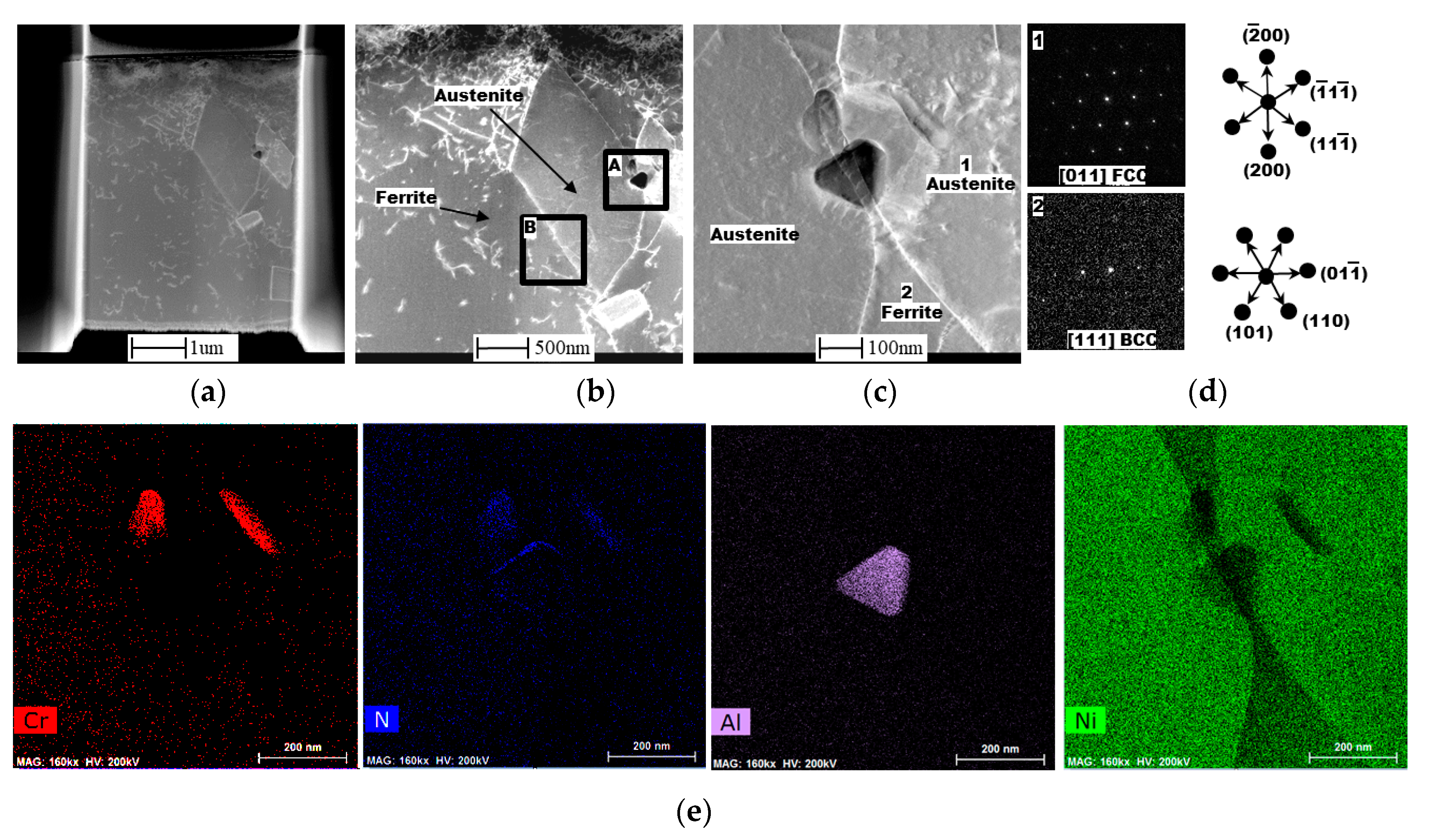
Figure 12.
TEM analysis result at ferrite-austenite phase boundary at location “A” of Figure 11b at non-reheated area: (a) precipitate at ferrite-austenite boundary; (b) X-ray pattern; (c) precipitate #1; and (d) precipitate #2.
Figure 12.
TEM analysis result at ferrite-austenite phase boundary at location “A” of Figure 11b at non-reheated area: (a) precipitate at ferrite-austenite boundary; (b) X-ray pattern; (c) precipitate #1; and (d) precipitate #2.

Figure 13.
TEM analysis result at reheated weld metal: (a) FIB-TEM; (b) Phase boundary; (c) Different angle of phase boundary; (d) Phase boundary at location “A” of Figure 13c; (e) High magnification of phase boundary at location “1” of Figure 13d; (f) X-ray pattern at phase boundary of location “a” of Figure 13e.


Table 1.
Chemical composition of base metal and welding wire.
| Material | Chemical Composition (wt %) | PREN 3 | |||||||
|---|---|---|---|---|---|---|---|---|---|
| C | Si | Mn | Cr | Ni | Mo | N | Other | ||
| Base metal 1 (UNS S32750) | 0.022 | 0.23 | 0.64 | 25.5 | 6.7 | 3.52 | 0.26 | Cu: 0.16 | 42.8 |
| Welding wire 2 (AWS ER2594) | 0.01 | 0.41 | 0.38 | 25.0 | 9.5 | 3.93 | 0.24 | - | 42.1 |
1 Diameter: 6 inch, Thickness: 7.11 mm; 2 AWS A5.9, Diameter: 2.4 mm; 3 PREN: wt % Cr + 3.3 × wt % Mo + 16 × wt % N.
Table 2.
Mechanical properties of base metal and weld metal.
| Material | Strength (MPa) | El. (%) | Absorbed Energy (J) | Ferrite Content (%) 1 | |
|---|---|---|---|---|---|
| Y.S. | T.S. | ||||
| Base metal (UNS S32750) | 561–625 | 812–856 | 34–42 | 120–231 @ −51 °C | 47.61–50.46 |
| Welding wire (AWS A5.9 ER2594) | 685 | 874 | 30 | 181–194 @ −50 °C | 44 |
1 Ferrite content was measured by ASTM E562.
Table 3.
Welding conditions of bead-on-pipe single pass welding.
| Current (A) | Voltage (V) | Welding Speed (cm/min) | Heat Input (kJ/cm) | Bead Width (mm) |
|---|---|---|---|---|
| 97 | 11 | 4.4 | 14.7 | 14.2 |
Table 4.
Summary of phase fraction at the edge and the center of weld based on EBSD results.
| Phase Volume Fraction (%) | Edge | Center | ||
|---|---|---|---|---|
| Ferrite | 83.8 | 72.2 | ||
| Austenite | 13.9 | 27.1 | ||
| Cr2N | 2.2 | 0.7 | ||
| Location | Non-Reheated WM | Reheated WM | Non-Reheated WM | Reheated WM |
| Ferrite | 92.9 | 72.1 | 77.2 | 67.2 |
| Austenite | 4.4 | 26.6 | 21.7 | 32.3 |
| Cr2N | 2.7 | 1.4 | 0.11 | 0.04 |
© 2017 by the authors. Licensee MDPI, Basel, Switzerland. This article is an open access article distributed under the terms and conditions of the Creative Commons Attribution (CC BY) license (http://creativecommons.org/licenses/by/4.0/).
Share and Cite
MDPI and ACS Style
Sung, H.-J.; Na, H.-S.; Kang, C.-Y. Effect of Dynamic Reheating Induced by Weaving on the Microstructure of GTAW Weld Metal of 25% Cr Super Duplex Stainless Steel Weld Metal. Metals 2017, 7, 490. https://doi.org/10.3390/met7110490
AMA Style
Sung H-J, Na H-S, Kang C-Y. Effect of Dynamic Reheating Induced by Weaving on the Microstructure of GTAW Weld Metal of 25% Cr Super Duplex Stainless Steel Weld Metal. Metals. 2017; 7(11):490. https://doi.org/10.3390/met7110490
Chicago/Turabian StyleSung, Hee-Joon, Hye-Sung Na, and Chung-Yun Kang. 2017. "Effect of Dynamic Reheating Induced by Weaving on the Microstructure of GTAW Weld Metal of 25% Cr Super Duplex Stainless Steel Weld Metal" Metals 7, no. 11: 490. https://doi.org/10.3390/met7110490
Note that from the first issue of 2016, this journal uses article numbers instead of page numbers. See further details here.