Revisiting Mg–Mg2Ni System from Electronic Perspective


1
Key Laboratory for Liquid-Solid Structural Evolution and Processing of Materials (Ministry of Education), Shandong University, Jinan 250061, China; Suzhou Institute of Shandong University, Suzhou 215000, China
2
Key Laboratory of Applied Technology of Sophisticated Analytical Instruments, Shandong Academy of Sciences, Jinan 250014, China
3
Condensed Matter Theory, Department of Physics and Astronomy, Ångström Laboratory, Uppsala University, SE-752 37 Uppsala, Sweden
4
Department of Materials Science and Engineering, KTH Royal Institute of Technology, S-100 44 Stockholm, Sweden
*
Author to whom correspondence should be addressed.
Metals 2017, 7(11), 489; https://doi.org/10.3390/met7110489
Submission received: 14 September 2017
/
Revised: 1 November 2017
/
Accepted: 6 November 2017
/
Published: 9 November 2017
Abstract
:Both Mg and Mg2Ni are promising electrode materials in conversion-type secondary batteries. Earlier studies have shown their single-phase prospects in electro-devices, while in this work, we have quantitatively reported the electronic properties of their dual-phase materials, that is, Mg–Mg2Ni alloys, and analyzed the underlying reasons behind the property changes of materials. The hypoeutectic Mg–Mg2Ni alloys are found to be evidently more conductive than the hypereutectic Mg–Mg2Ni system. The density functional theory (DFT) calculations give the intrinsic origin of electronic structures of both Mg2Ni and Mg. The morphology of quasi-nanoscale eutectics is another factor that can affect the electronic properties of the investigated alloy system; that is, the electrical property change of the investigated alloys system is due to a combination of the intrinsic property difference between the two constituting phases and the change of eutectic microstructures that affect electron scattering. In addition, regarding the Mg–Mg2Ni alloy design for device applications, the electronic property and mechanical aspect should be well balanced.
1. Introduction
In the context of limited fossil-fuel reserves and their induced environmental pollution problems, green or renewable energy research has been a focus point all over the world. Among this research, one of the main trends is to use less traditional fuels and instead widen the usage of electricity, which can be generated from several renewable energy resources such as solar, wind, bio-mass, and so forth. Therefore, electrical energy storage is becoming an ever more important research topic. This issue is becoming more emphasized as the current utilization of electricity is moving from small-sized consumer electronics to large-scale electric vehicles, the smart grid and other industrial systems [1,2,3,4,5,6]. The technology of Li-ion or Na-ion batteries is a promising solution to tackle the energy storage problems, although the technology is still facing many challenges in meeting technical requirements and in cost-efficiency [7,8,9,10,11,12,13]. Differently from many traditional studies on electrode materials such as the intercalation type or the alloying type, Y. Oumellal et al. reported a new concept to use metal hydrides as conversion electrodes with high capacities for Li-ion battery applications [14,15]. Until now, some single-phase metal hydrides such as MgH2 and Mg2NiH4 have been experimentally considered in related studies and have shown good electrochemical properties for battery conversion anode applications. Their conversion mechanism can be represented by the following reactions, respectively:
Mg + 2LiH = MgH2 + 2Li+ + 2e−
Mg2Ni + 4LiH = Mg2NiH4 + 4Li+ + 4e−
Because the electronic conductivity of LiH phase is poor, the Mg- or Mg2Ni-phase would play an important role as an electrode conductor in their respective battery systems. This inspires one idea/question, that is, what will their electronic properties be if we combine the Mg- and Mg2Ni-phase in the form of alloy? In order to find the answer, in this work we have fabricated several Mg–Mg2Ni alloys with different compositions and aimed to unveil the relationship between the electronic properties and structures of the alloy system by means of experiments and density functional theory (DFT) calculations. This work is proposed to supply first-hand data on basic electronic properties of the Mg–Mg2Ni alloy system and help to guide the choice of proper Mg–Mg2Ni dual-phase material for secondary battery or other device applications.
2. Materials and Methods
The examined alloys were prepared in a 5 kW electric furnace using 99.85% commercial purity bulk Mg and Ni–20 wt % Mg master alloy. The RJ-2 flux containing mainly MgCl2 and KCl were used for melt protection and refining. Four compositions of Mg–Ni alloys (Mg–8.8Ni, Mg–14Ni, Mg–25.6Ni, and Mg–31Ni; all in wt % and marked as alloys A, B, C and D, respectively) together with pure Mg were designed and obtained in this work and were measured by means of a QSN750 spectrometer (OBLF company, Dortmund, Germany). After melting, the melts were respectively cast into a cylindrical steel mold preheated to 200 °C with size of Ø25 mm × 60 mm. For microstructural analysis and comparison, all samples were taken from the middle position along the radius direction of the ingots. A Hitachi-430 field emission gun scanning electron microscope (FEG-SEM) affiliated with energy-dispersive X-ray spectroscopy (EDX) was employed to characterize the microstructures of the alloys. The electronic conductivity measurements were taken using a RS.03-DX200H electrical resistivity meter (Honghu company, Xi’an, China) according to the ASTM B193 standard. The hardness test bars were machined to the cube-type specimens (30 mm × 20 mm × 20 mm) and then tested on a HBS-3000 digital Brinell hardness tester according to the ASTM E10-14 standard.
The electronic structure calculations were performed using DFT [16,17] spin-polarized calculations with the projector augmented-wave (PAW) method [18], as implemented in the Vienna Ab initio simulation package [19,20]. The exchange-correlation interaction was considered in a generalized gradient approximation using the Perdew–Burke–Ernzerhof (PBE) scheme [21]. A K-points mesh of 21 × 21 × 7 was used in calculations and a plane-wave basis set with an energy cutoff of 500 eV was employed to describe the electronic wave function. The geometry optimization was done by minimizing the forces on atoms with a conjugate gradient algorithm and simultaneously minimizing stresses on unit cells without any symmetry constraint. An electronic convergence criterion of 0.00001 eV and ionic relaxation convergence criterion of 0.002 eV/Å were employed in the work. During the calculations, the spin polarization was considered. An electron localization function analysis was performed on the basis of the quantum solid state theory.
3. Results and Discussion
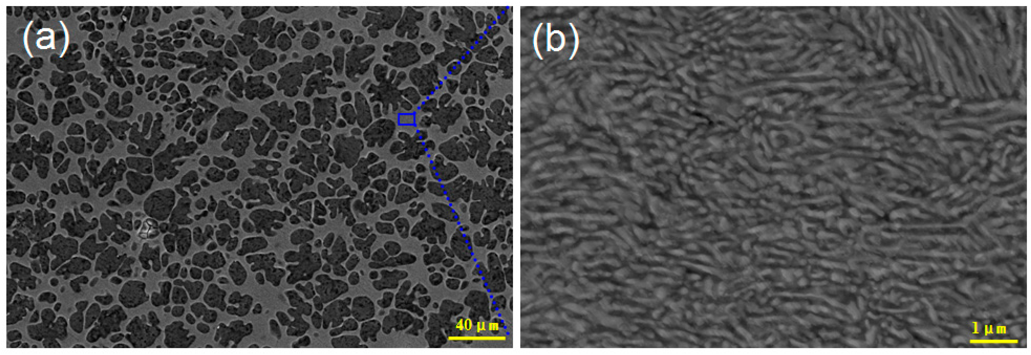
The microstructure of the fabricated Mg–8.8Ni alloy is shown in Figure 1a, from which it can be seen that the alloy consists of the primary Mg-phase and the eutectic region. The size of the precipitated primary Mg-phase during solidification is large and the dendrites constitute the majority of the volume fractions in the alloy. Figure 1b shows the magnified microstructure of the eutectic region. It was found that a lamellar eutectic structure is formed in the Mg–Mg2Ni system, in which the white and black plate-like phases are eutectic Mg2Ni and eutectic Mg-phase, respectively. It is interesting that the spacing between alternated congeneric phases in the lamellar eutectic is of the quasi-nanoscale and that there occurs some growth orientation inside the eutectic colony.
The microstructure of the Mg–14Ni alloy with an increase in the content of Ni in the alloy is shown in Figure 2a. It can be seen that the microstructure is still hypoeutectic with the primary Mg-phase and eutectic region, while the difference is that the size of the primary Mg-phase becomes smaller compared with that in alloy A and the volume fraction of the eutectic region in alloy B becomes larger. Figure 2b represents the microstructure of the Mg–Mg2Ni eutectic region, from which it can be found that the growth orientation of the eutectic phases is not evident in this alloy. Compared with the case in alloy A, the eutectic phase spacing is still of the quasi-nanoscale, but the eutectic structure is characterized by being undirectional.
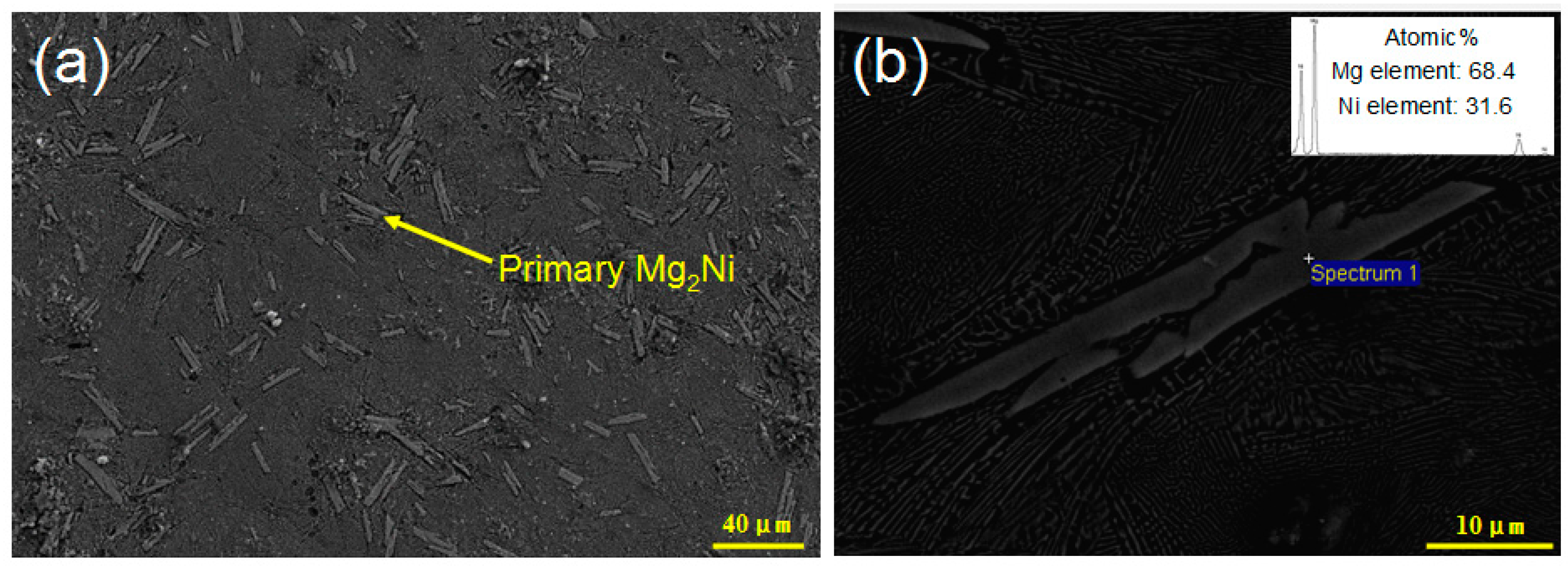
The microstructure of the Mg–25.6Ni alloy is shown in Figure 3. Evidently, the alloy becomes hypereutectic in this composition. The primary phase is no longer the Mg-phase and instead is primary Mg2Ni characterized by a sharp rod-like morphology. The EDX analysis confirms the phase has an average length of around 40 μm. Besides the primary Mg2Ni, the eutectic region also constitutes the whole microstructure of the alloy. Similarly to alloy A, the eutectic structure in alloy C is also lamellar with eutectic Mg2Ni and eutectic Mg-phases arranged alternatively. There exists local growth orientation inside the eutectic colony in alloy C.
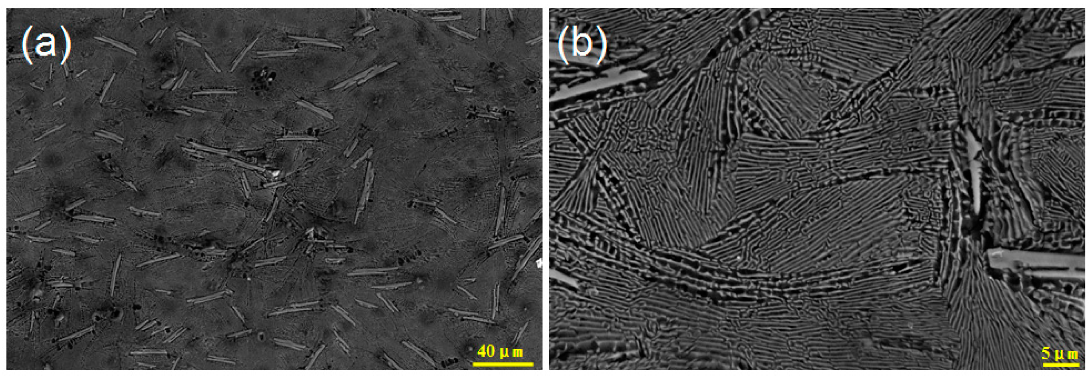
Figure 4a illustrates the microstructure of the Mg–31Ni alloy, for which the content of Ni is further increased. Compared with the case in alloy C, it can be seen that both the amount and the size of the primary Mg2Ni phases become larger in alloy D. Figure 4b shows the magnified structure of the eutectic region. It is found that the (Mg + Mg2Ni) eutectics are characterized by a kind of “tendon-like” intersection with quasi-nanoscale lamellar spacing. The growth orientation is evident inside the local eutectic colony.
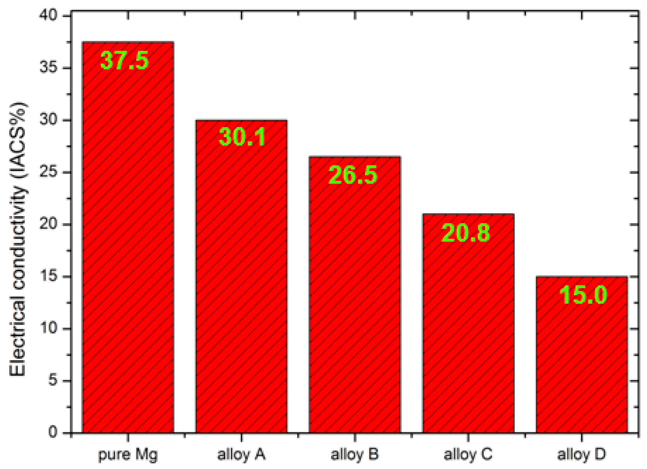
After comparing the microstructures of above alloys, we measured their electrical properties, and Figure 5 shows the results of electronic conductivity. It can evidently be seen that all the alloys are less conductive than pure Mg. With the increase of the Ni content in the alloy, the material system shows a declining trend in the electronic conductivity. Particularly, when the amount of primary Mg2Ni is the greatest in alloy D, the electronic conductivity is only 15 IACS% (International Annealed Copper Standard) with a decrease of 60% compared with pure Mg. For battery electrode applications, one of the most important properties is electronic conductivity. Thus, from this perspective, the future Mg–Mg2Ni alloy electrode should not contain a great deal of primary Mg2Ni but should instead try to maintain a hypoeutectic composition.
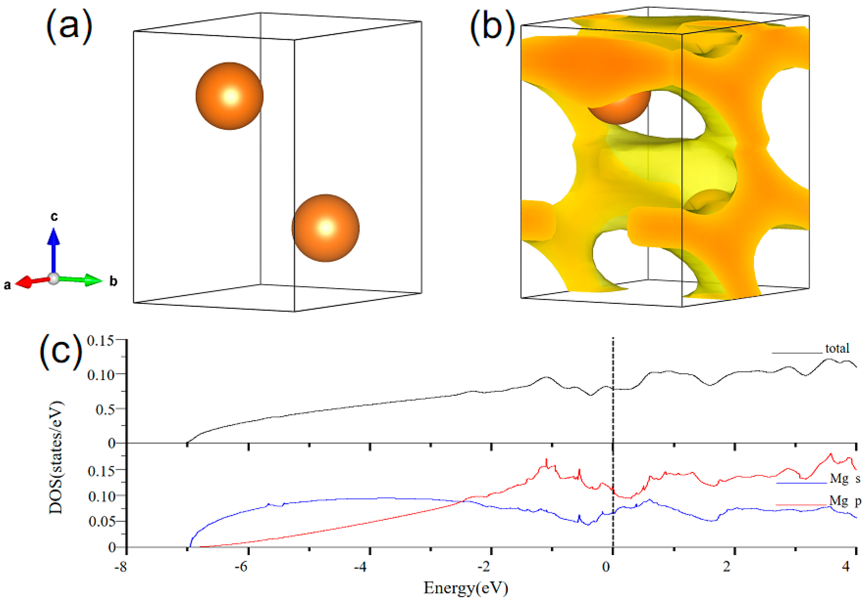
From quantum theory, the electronic structure is the origin of electrical properties. We have calculated the electronic structures of both Mg and Mg2Ni using DFT. The atomic and electronic structure of Mg2Ni is shown in Figure 6. The calculated equilibrium crystal structure (P6222 space group) of Mg2Ni is illustrated in Figure 6a. The unit cell consists of 18 atoms with Mg atoms having 4 occupation sites and Ni atoms having 2 sites, which are labelled in the figure. Figure 6b shows the calculated electron localization function (ELF) isosurface with the nature of metallic bonding but illustrates some electron localization in red, which is negatively related to the electron transfer in materials. The total and partial density of states (DOS) is seen in Figure 6c. The total DOS is mainly contributed by the s states of Mg atoms and the d state of Ni2 atoms. There occurs orbital hybridization between the d orbital of Ni2 atoms and the p orbitals of Mg2 or Mg4 atoms, which contributes to the Mg–Ni chemical bonding. As seen from the DOS of Mg2Ni, there are not many states available for occupation at the Fermi level. Figure 7a,b represents the unit cell and calculated ELF of pure Mg (hcp structure). With metallic bonding, the free electrons in Mg contribute greatly to its electrical conductivity. Figure 7c is the calculated total and partial DOS of pure Mg. The p state of Mg contributes the most to the total DOS at the Fermi level.
Besides the above analysis of the electronic structures’ nature, the microstructure scale of the alloys can also affect their electrical properties. Taking alloy B as an example, the disordered arrangement of the eutectics will scatter electrons more than the oriented eutectic structure in alloy A. Alloy D is another typical material to be discussed. When we analyze its low electronic conductivity, two main factors should be considered: the intrinsic property of the primary Mg2Ni-phase and the morphology of eutectics. As is known from the above, the intrinsic Mg2Ni-phase is less conductive than the Mg phase. In addition, the “tendon-like” intersection of eutectics that cause severe electron scattering in the alloy is also not beneficial for electronic conductivity.
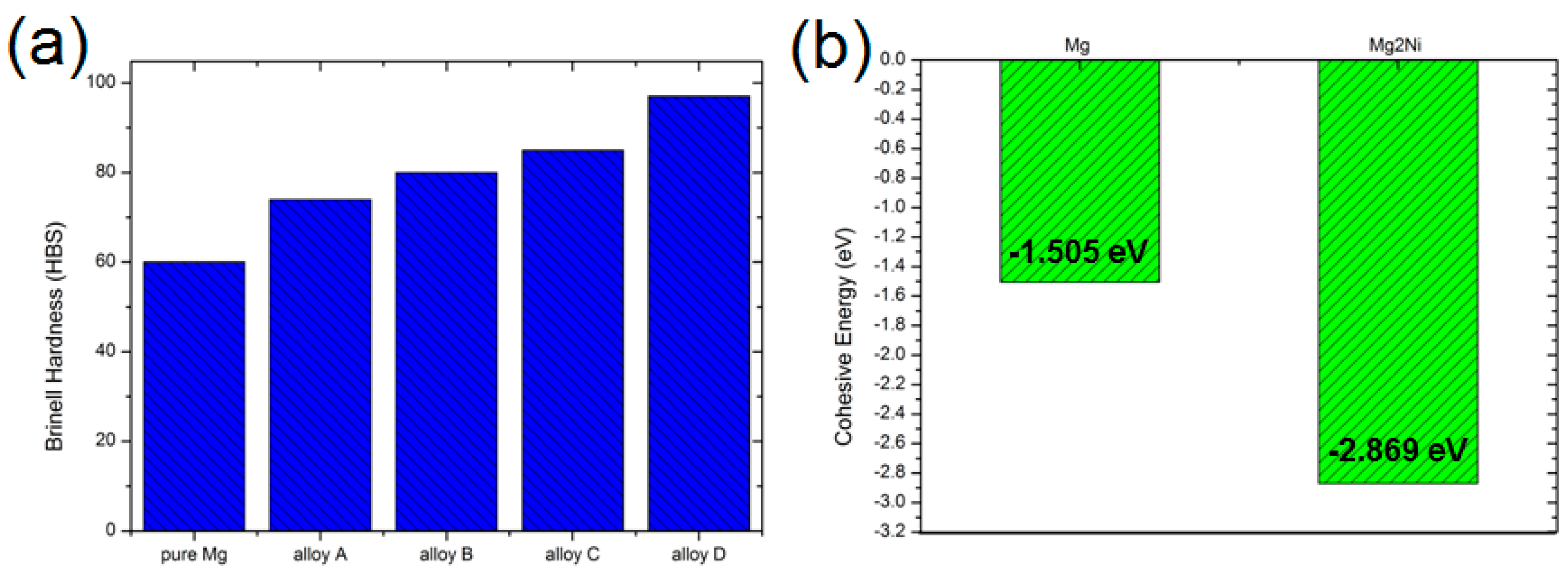
From the above results, it seems that alloy A with a higher electronic conductivity than the other alloys is the best choice for the battery electrode. However, the electrode material should also have good mechanical properties. Thus, hardness testing of these Mg–Mg2Ni alloys has also been carried out. Figure 8a shows the Brinell hardness comparison, from which it can be seen that the hardness of the alloy is enhanced with an increase in the Ni content; that is, the existence of primary Mg2Ni improves the mechanical hardness of the alloy more so than for the primary Mg-phase. These experimentally measured results correspond qualitatively with the DFT calculations. Figure 8b gives the cohesive energies of pure Mg and Mg2Ni, which can reflect the bonding strength of the matter. The calculations are based on the formula below:
where E(AxBy) is the total energy of the matter AxBy, while E(A) and E(B) stand for the spin-polarized ground-state total energies of atoms A and B, respectively. Evidently, the value of Mg2Ni is more negative (−2.869 eV). This makes Mg2Ni act stronger when the alloy is under mechanical load. The properties of electronic conductivity and mechanical hardness should be well balanced when choosing the right composition in a Mg–Mg2Ni alloy system for device electrode applications.
4. Summary and Outlook
In this study, the microstructures and electrical properties of several hypoeutectic and hypereutectic Mg–Mg2Ni alloys have been investigated, and the structure–property relationship has also been analyzed. In hypereutectic Mg–Mg2Ni alloy, the primary Mg2Ni-phase is characterized by a sharp rod-like morphology. As for the eutectic structure in the alloy, the quasi-nanoscale spacing between the eutectic Mg-phase and eutectic Mg2Ni-phase has been found. DFT calculations revealed the superior electronic conductivity of Mg over Mg2Ni, which makes the electrical property of the hypoeutectic Mg–Mg2Ni alloy system better than that of the hypereutectic alloy system. Besides the property of good electrical conductivity that the battery material should have, the mechanical property has also been assessed and balanced among the studied alloys. It is proposed that this study creates a new perspective to investigate the Mg–Mg2Ni system and will encourage more research to focus on this alloy system for electro-device or other functional applications.
Acknowledgments
We would like to thank the Jiangsu Province Science Foundation for Youths (BK20160370), the Natural Science Foundation of Shandong Province (ZR2015EQ012 and ZR2014YL003), the China Postdoctoral Science Foundation (2015M572028) and the Shandong Postdoctoral Innovation Program (201602019) for support. The Natural Science Foundation of China (51731007) and the Fundamental Research Fund of Shandong University (2015TB001) are also gratefully acknowledged.
Author Contributions
Zhao Qian conceived and designed the study; Zhao Qian, Weimin Guo, Guanzhong Jiang and Shaokun Xu performed the experiments and calculations; Zhao Qian, Rajeev Ahuja and Xiangfa Liu analyzed the data; Zhao Qian wrote the paper.
Conflicts of Interest
The authors declare no conflict of interest.
References
- Grey, C.P.; Tarascon, J.M. Sustainability and in situ monitoring in battery development. Nat. Mater. 2017, 16, 45–56. [Google Scholar] [CrossRef] [PubMed]
- Pan, H.; Hu, Y.; Chen, L. Room-temperature stationary sodium-ion batteries for large-scale electric energy storage. Energy Environ. Sci. 2013, 6, 2338–2360. [Google Scholar] [CrossRef]
- Wang, X.; Guo, X.; Chen, J.; Ge, C.; Zhang, H.; Liu, Y.; Zhao, L.; Zhang, Y.; Wang, Z.; Sun, L. Au nanoparticles decorated graphene/nickel foam nanocomposite for sensitive detection of hydrogen peroxide. J. Mater. Sci. Technol. 2017, 33, 246–250. [Google Scholar] [CrossRef]
- Kim, T.H.; Park, J.S.; Chang, S.K.; Choi, S.; Ryu, J.H.; Song, H.K. The Current Move of Lithium Ion Batteries towards the Next Phase. Adv. Energy Mater. 2012, 2, 860–872. [Google Scholar] [CrossRef]
- Armstrong, A.R.; Lyness, C.; Panchmatia, P.M.; Islam, M.S.; Bruce, P.G. The lithium intercalation process in the low-voltage lithium battery anode Li1+xV1−xO2. Nat. Mater. 2011, 10, 223–229. [Google Scholar] [CrossRef] [PubMed]
- Goodenough, J.B.; Kim, Y. Challenges for rechargeable Li batteries. Chem. Mater. 2010, 22, 587–603. [Google Scholar] [CrossRef]
- Armand, M.; Tarascon, J.-M. Building better batteries. Nature 2008, 451, 652–657. [Google Scholar] [CrossRef] [PubMed]
- Qian, Z.; Sarkar, A.D.; Maark, T.A.; Jiang, X.; Deshpande, M.D.; Bououdina, M.; Ahuja, R. Pure and Li-doped NiTiH: potential anode materials for Li-ion rechargeable batteries. Appl. Phys. Lett. 2013, 103, 033902. [Google Scholar] [CrossRef]
- Obrovac, M.N.; Christensen, L.; Le, D.B.; Dinh, J.R. Alloy design for lithium-ion battery anodes. J. Electrochem. Soc. 2007, 154, A849–A855. [Google Scholar] [CrossRef]
- Tarascon, J.-M.; Grugeon, S.; Morcrette, M.; Laruelle, S.; Rozier, P.; Poizot, P. New concepts for the search of better electrode materials for rechargeable lithium batteries. C. R. Chim. 2005, 8, 9–15. [Google Scholar] [CrossRef]
- Nazri, G.-A.; Pistoia, G. Lithium Batteries: Science and Technology; Springer: New York, NY, USA, 2009. [Google Scholar]
- Poizot, P.; Laruelle, S.; Grugeon, S.; Dupont, L.; Tarascon, J.-M. Nano-sized transition-metal oxides as negative-electrode materials for lithium-ion batteries. Nature 2000, 407, 496–499. [Google Scholar] [CrossRef] [PubMed]
- Qian, Z.; Jiang, X.; Sarkar, A.D.; Maark, T.A.; Deshpande, M.D.; Bououdina, M.; Johansson, B.; Ahuja, R. Screening study of light-metal and transition-metal-doped NiTiH hydrides as Li-ion battery anode materials. Solid State Ion. 2014, 258, 88–91. [Google Scholar] [CrossRef]
- Oumellal, Y.; Rougier, A.; Nazri, G.A.; Tarascon, J.-M.; Aymard, L. Metal hydrides for lithium-ion batteries. Nat. Mater. 2008, 7, 916–921. [Google Scholar] [CrossRef] [PubMed]
- Oumellal, Y.; Rougier, A.; Tarascon, J.-M.; Aymard, L. 2LiH + M (M = Mg, Ti): New concept of negative electrode for rechargeable lithium-ion batteries. J. Power Sources 2009, 192, 698–702. [Google Scholar] [CrossRef]
- Hohenberg, P.; Kohn, W. Inhomogeneous electron gas. Phys. Rev. 1964, 136, B864–B871. [Google Scholar] [CrossRef]
- Kohn, W.; Sham, L.J. Self-consistent equations including exchange and correlation effects. Phys. Rev. 1965, 140, A1133–A1138. [Google Scholar] [CrossRef]
- Blöchl, P.E. Projector augmented-wave method. Phys. Rev. B 1994, 50, 17953–17979. [Google Scholar] [CrossRef]
- Kresse, G.; Hafner, J. Ab initio molecular dynamics for open-shell transition metals. Phys. Rev. B 1993, 48, 13115–13118. [Google Scholar] [CrossRef]
- Kresse, G.; Furthmüller, J. Efficient iterative schemes for ab initio total-energy calculations using a plane-wave basis set. Phys. Rev. B 1996, 54, 11169–11186. [Google Scholar] [CrossRef]
- Perdew, J.P.; Burke, K.; Ernzerhof, M. Generalized gradient approximation made simple. Phys. Rev. Lett. 1996, 77, 3865–3868. [Google Scholar] [CrossRef] [PubMed]
Figure 1.
(a) Microstructure of Mg–8.8Ni alloy (designated as alloy A in this study), and (b) the magnified scanning electron microscopy image of the eutectic region.
Figure 1.
(a) Microstructure of Mg–8.8Ni alloy (designated as alloy A in this study), and (b) the magnified scanning electron microscopy image of the eutectic region.
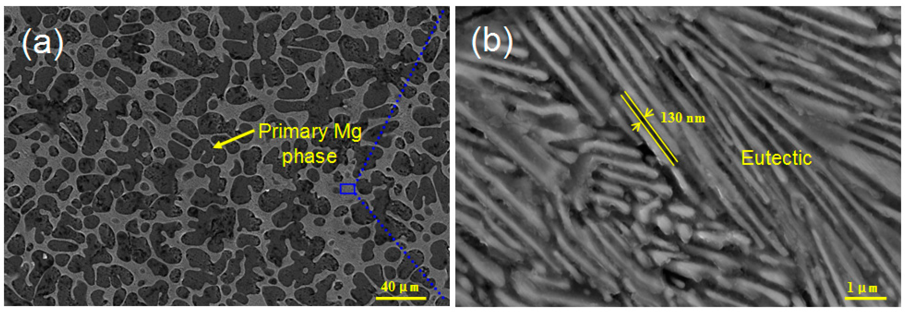
Figure 2.
(a) Microstructure of Mg–14Ni alloy (designated as alloy B), and (b) the magnified scanning electron microscopy image of the eutectic region.
Figure 2.
(a) Microstructure of Mg–14Ni alloy (designated as alloy B), and (b) the magnified scanning electron microscopy image of the eutectic region.

Figure 3.
(a) Microstructure of Mg–25.6Ni alloy (designated as alloy C), and (b) the morphology and energy-dispersive X-ray spectroscopy result of the primary Mg2Ni.
Figure 3.
(a) Microstructure of Mg–25.6Ni alloy (designated as alloy C), and (b) the morphology and energy-dispersive X-ray spectroscopy result of the primary Mg2Ni.

Figure 4.
(a) Microstructure of Mg–31Ni alloy (designated as alloy D), and (b) the morphology of the eutectic region.
Figure 4.
(a) Microstructure of Mg–31Ni alloy (designated as alloy D), and (b) the morphology of the eutectic region.

Figure 5.
Quantitative electrical conductivities of the investigated Mg–Mg2Ni alloys system.

Figure 6.
(a) The calculated equilibrium crystal structure, (b) electron localization function (isosurface level of 0.285), and (c) electronic density of states of Mg2Ni (the Fermi level is set at zero).
Figure 6.
(a) The calculated equilibrium crystal structure, (b) electron localization function (isosurface level of 0.285), and (c) electronic density of states of Mg2Ni (the Fermi level is set at zero).
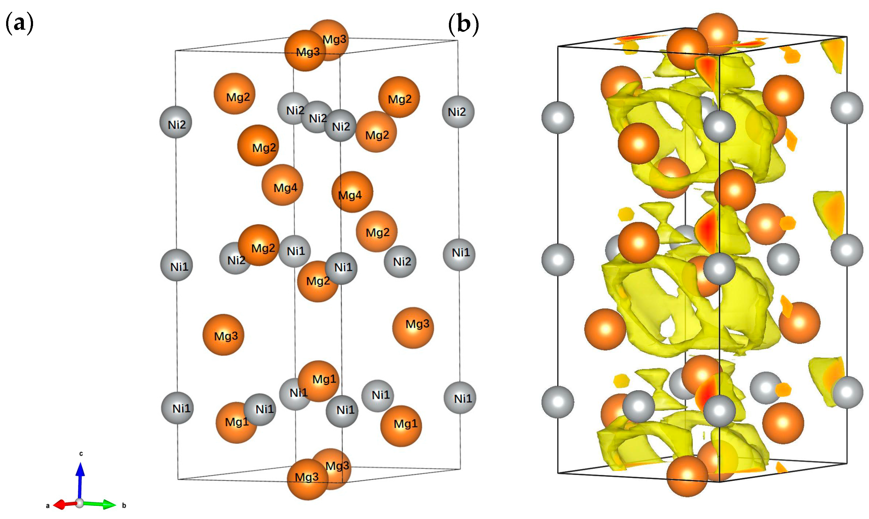
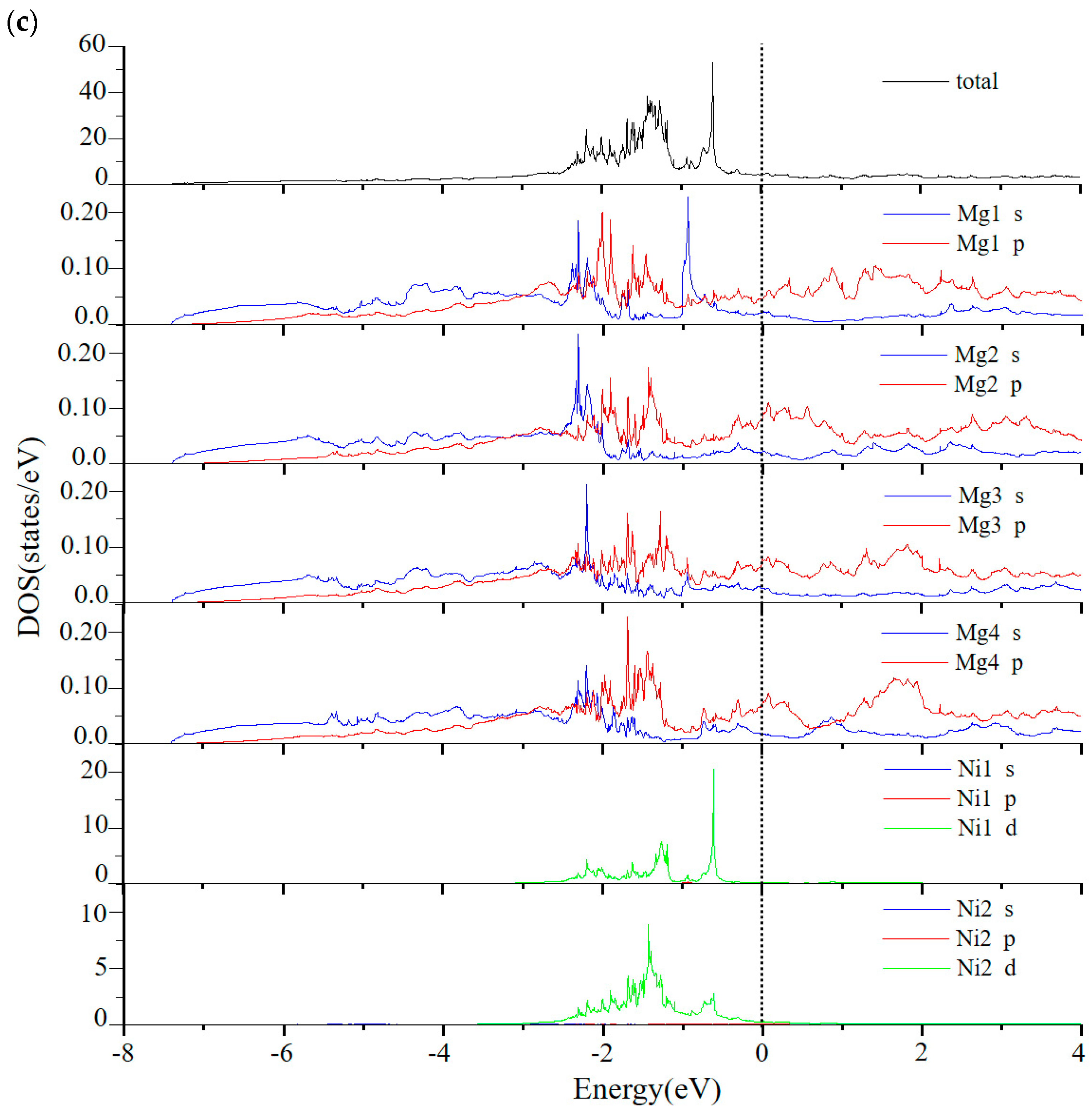
Figure 7.
(a) The unit cell, (b) the calculated electron localization function (isosurface level of 0.567), and (c) electronic density of states of pure Mg (the Fermi level is set at zero).
Figure 7.
(a) The unit cell, (b) the calculated electron localization function (isosurface level of 0.567), and (c) electronic density of states of pure Mg (the Fermi level is set at zero).

Figure 8.
(a) Brinell hardness of the investigated Mg–Mg2Ni alloy system, and (b) the calculated cohesive energies of Mg and Mg2Ni from density functional theory.
Figure 8.
(a) Brinell hardness of the investigated Mg–Mg2Ni alloy system, and (b) the calculated cohesive energies of Mg and Mg2Ni from density functional theory.

© 2017 by the authors. Licensee MDPI, Basel, Switzerland. This article is an open access article distributed under the terms and conditions of the Creative Commons Attribution (CC BY) license (http://creativecommons.org/licenses/by/4.0/).
Share and Cite
MDPI and ACS Style
Qian, Z.; Guo, W.; Jiang, G.; Xu, S.; Ahuja, R.; Liu, X. Revisiting Mg–Mg2Ni System from Electronic Perspective. Metals 2017, 7, 489. https://doi.org/10.3390/met7110489
AMA Style
Qian Z, Guo W, Jiang G, Xu S, Ahuja R, Liu X. Revisiting Mg–Mg2Ni System from Electronic Perspective. Metals. 2017; 7(11):489. https://doi.org/10.3390/met7110489
Chicago/Turabian StyleQian, Zhao, Weimin Guo, Guanzhong Jiang, Shaokun Xu, Rajeev Ahuja, and Xiangfa Liu. 2017. "Revisiting Mg–Mg2Ni System from Electronic Perspective" Metals 7, no. 11: 489. https://doi.org/10.3390/met7110489
Note that from the first issue of 2016, this journal uses article numbers instead of page numbers. See further details here.