Thermally-Induced Crack Evaluation in H13 Tool Steel
by

Hassan Abdulrssoul Abdulhadi
1,2,*, 
Syarifah Nur Aqida Syed Ahmad
1,
Izwan Ismail
3,
Mahadzir Ishak
1 and
Ghusoon Ridha Mohammed
1,2 1
Faculty of Mechanical Engineering, University Malaysia Pahang, 26600 Pekan, Pahang, Malaysia
2
Baghdad Institute, Middle Technical University, Baghdad 10074, Iraq
3
Faculty of Manufacturing Engineering, University Malaysia Pahang, 26600 Pekan, Pahanag, Malaysia
*
Author to whom correspondence should be addressed.
Metals 2017, 7(11), 475; https://doi.org/10.3390/met7110475
Submission received: 24 September 2017
/
Revised: 21 October 2017
/
Accepted: 26 October 2017
/
Published: 6 November 2017
(This article belongs to the Special Issue Fatigue and Wear for Steels)
Abstract
:This study reported the effect of thermal wear on cylindrical tool steel (AISI H13) under aluminum die-casting conditions. The AISIH13 steels were immersed in the molten aluminum alloy at 700 °C before water-quenching at room temperature. The process involved an alternating heating and cooling of each sample for a period of 24 s. The design of the immersion test apparatus stylistically simulated aluminum alloy dies casting conditions. The testing phase was performed at 1850, 3000, and 5000 cycles. The samples were subjected to visual inspection after each phase of testing, before being examined for metallographic studies, surface crack measurement, and hardness characteristics. Furthermore, the samples were segmented and examined under optical and Scanning Electron Microscopy (SEM). The areas around the crack zones were additionally examined under Energy Dispersive X-ray Spectroscopy (EDXS). The crack’s maximum length and Vickers hardness profiles were obtained; and from the metallographic study, an increase in the number of cycles during the testing phase resulted in an increase in the surface crack formation; suggesting an increase in the thermal stress at higher cycle numbers. The crack length of Region I (spherically shaped) was about 47 to 127 µm, with a high oxygen content that was analyzed within 140 µm from the surface of the sample. At 700 °C, there is a formation of aluminum oxides, which was in contact with the surface of the H13 sample. These stresses propagate the thermal wear crack length into the tool material of spherically shaped Region I and cylindrically shape Region II, while hardness parameters presented a different observation. The crack length of Region I was about 32% higher than the crack length of Region II.
1. Introduction
It is crucial in aluminium die casting to manufacture more than 100,000 castings per die application, but this often results in die failures. Meanwhile, the viability of the provisional tools determines the fabrication cost, and it is influenced by the material choice, heating mechanics, tool design, and constraints [1,2]. The surface of dies easily wears during the casting of components with complicated geometries. Moreover, in the presence of defects due to erosion within the die, there is always a contact between the die surface and the molten material, which will subsequently lead to intense erosive reaction after many cycles [3].
Some of the prominent die failures noted includes washouts, soldering defects due to die-molten metal contact, and thermal cracks [4,5,6,7,8]. In mild conditions, materials can withstand thermal strains and their associated stress over many thermal cycles before cracking, but in severe conditions, cracks can develop within few cycles. Components with relatively higher sizes experience higher surface contraction or expansion when exposed to thermal strain. Maiya and Burke [9] have demonstrated an increase in life when sheet-metals are exposed to tests for thermal fatigue, with a decrease in the thickness. Visser [10] stated that solid cylindrical samples, when subjected to rapid alternate heating and cooling cycles would have a weakened thermal tolerance as the radius increases.
There is a direct correlation between crack propagation and the local plastic strain aggregation, which occur during each casting cycle. The cracked surface oxidation initially facilitates the propagation of cracking, while the continued growth is smoothed by the combined effects of crack filling of the cast material, oxidation and ductility of the tool material. The interaction of a molten metal with a die increases the surface temperature, raising it more than the temperature of the interior [11,12,13,14,15,16,17,18,19,20,21].
The evolution of thermal wear and cracks in tool steel samples at different thermal wear cycles and locations was investigated in this study. The samples are initially immersed in molten aluminum, before being quenched in water bath at room temperature. At the end of each testing cycle, the processed samples were examined for the development of metallurgical and mechanical behaviors, as well as checking for the initiation of thermal cracks [22,23,24]. The oxidation and thermal cycle-induced damages on the sample’s surfaces and transverse sections were examined under optical microscopy and Scanning Electron Microscopy (SEM). Additionally, the micro-hardness profiles of the cycled specimens were assessed for behavioral changes after cyclic immersion tests.
2. Materials and Methods
Material
AISI H13 tool steel and aluminium 356 alloys were employed in this study. Their chemical configurations are shown in Table 1. The outer and inner diameter of the samples was 33 and 20 mm, respectively (Figure 1a,b).
The specimens were introduced into the molten aluminium at 700 °C, before being quenched in a water bath at 32 °C for 7 s. This is to the sticking of aluminium on the test specimens, and to generate thermal gradients during the cooling process. The cooled samples were then passed through air at 28 °C for 5 s, before re-immersing into the molten aluminium alloy at 700 °C for another 24 s. The samples were then, cooled for 5 s in air and 7 s in water. The enabling of a cyclical movement between the molten aluminium, air, and water baths ensured the achievement of thermal wear loading. The inner wall of the samples was cooled through water spraying at 32 °C for 3 s. Thermal wear tests were performed at 1850, 3000, and 5000 cycles in succession. K-type thermocouples were attached to the procedure to measure the changes in temperature during the thermal cycles.
During the experiments, an oxide coating was generated on the metallic sample surface, which subsequently shielded the resulting damages. Thus, a chemical cleaning process was performed to remove the outer oxide layer and to prevent any surface imposition. The samples were initially immersed in a boiling solution of saturated NaOH for 60 s, then dipped in 10% HCl solution for 10 s, before dipping in boiling distilled water for 60 s. The last two dipping steps were necessary for the completion of the NaOH reactions and to eradicate the chlorides on the sample surface. The sample surfaces were periodically examined through optical microscopy (MT8000 Series Metallurgical Microscopes, Microscope.com, Roanoke, VA, USA) and SEM (HITACHI Tabletop Microscope TM3030Plus, Hitachi High Technologies America, Inc., Schaumburg, IL, USA). For every immersion cycle, a sample from the final treatment step was selected for characterization. The transverse section of the samples (cycled) was examined for micro-hardness, microstructural changes, and detrimental penetration depth.
The specimens (now thermally worn) were examined for cracks, hardness, and metallographically. The metallographic investigation and crack analysis were carried out on longitudinal cross-sections of the sample using Energy Dispersive X-ray Spectroscopy (EDXS), (HITACHI Tabletop Microscope TM3030Plus, Hitachi High Technologies America, Inc. Schaumburg, IL, USA) and SEM. The length of the surface cracks was determined using image analysis software. The sample hardness across the sample thickness was measured with Vickers indenter to determine the stability of the H13 steel structure to high temperature.
3. Results and Discussion
3.1. Metallographic Study
Figure 2 shows the observed cracks on the surface of the thermally worn sample. There was a large surface crack of 28.3 µm in width due to the great temperature difference from the heating and cooling on samples. The Figure also showed the number of cycles for the initiation of the first thermal fatigue cracks. Figure 2a–c shows that the thermal cracks occurred at 1850, 3000, and 5000 cycles, respectively. Wear is a mechanical flux action against the die, while thermal wear results from repeated tension and compression due to rapid heating and cooling [13].
The maximum crack length at different thermal wear cycles is also shown in Figure 2, where the longest surface cracks occurred near Region I due to a higher temperature gradient from the operation temperature of 700 °C at the external surface, and 32 °C temperature on the inner surface. A great temperature difference can result in thermal stress on the sample’s outer surface [25]. The mean crack length value varied from 42.2 to 111.2 µm in length depending on the cycle number. The cracks formation resulted from the continuous material contraction and thermal expansion during the heating and cooling cycles. Variations in the microstructure and substantial structure of the sample resulted from the exposure of the die surface to high temperatures. The interaction between the die surface and the hot melt resulted also in decreased physical properties in terms of the strength and resistance of the material [26]. Furthermore, there was a local plastic distortion due to the increase in the local cracks, which eventually spread failures as die usage increases [27,28]. In addition, these areas experienced melt shocks, resulting in a decrease in the die life.
The relationship between crack length and cycle number is shown in Figure 3a,b. Region I and Region II in the figures represent the round ended samples and cylindrically shaped surfaces. There were evident cracks on the sample surface and in the cross-sections. Figure 3a,b represent the mean and maximum crack lengths at different cycles; the crack length propagated from 16.3 to 47.2 µm (Figure 3a), while the maximum crack length propagated from 53.2 to 127.2 µm (Figure 3b). The cracks presumed to occur near the die surface; where there was a high thermal stress due to a higher temperature gradient. The stress was additionally enhanced by the local stress concentrators, leading to a local accumulation of plastic strain.
There were variations in these cracks in terms of the shape, size, and density, based on their position from the die surface. Additionally, they varied in their depths, which increased as they approach the die, with melt and temperature being increased by the casting process. The surface locations of Region I witnessed the deepest cracks, which were enlarged because of the melt erosion (two or more cracks merged at some locations) [29]. The surface composition between the cracks was eliminated by this merging, thereby, generating wide cracks.
The thermal wear level was observed at locations that were far from the die surface. The lower strength of the material and the thermal fatigue on the surface of the die produced thermos-mechanical loads that surpass the elastic strength; leading to crack nucleation and local material failure [7,14]. Under SEM, typical thermal cracks were observed at different resolutions (Figure 2). There were cracks in the material’s microstructure; wide cracks exhibited oxidized surfaces in a molten number of cycles.
3.2. Energy Dispersive X-ray Spectroscopy (EDXS) Analysis
There seems to be a homogenous distribution of aluminium and oxygen, though oxygen inter-penetration was continuous. Oxygen penetration after thermal wear process was monitored through EDXs mapping (Figure 4). The molten Al was found to penetrate through the cracking and react with the steel to form Fe-Al intermetallic compound. These compounds lead to the main defect, such as cracks. The micro cracks are the most likely factors causing the penetration of molten aluminium into the crack. Other factors such as the reaction between the H13 and molten aluminium can affect the thermal wear in liquid. The result of the immersion test may be affected by Iron (Fe) atoms from the steel surface layer, which diffuse into the surface and react with oxygen. The Cr, Mo, and Fe levels were low near the crack boundary, because, above 500 °C, substitution diffusion is likely to occur, and alloy carbides can displace the less stable cementite and dissolve into a finer alloy carbide dispersion form [30]. The vacancies on the surface of the steel layer were occupied by the alloying components. The effect of silicon and aluminium can be caused by the short crack within the surface, meaning that they were in contact with the molten aluminium alloy. There was a negative effect of the oxide layer, it was at is its lowest thermal expansion and higher volume and fragility.
The external side of the crack surface was occupied by oxygen, thereby, facilitating crack growth on the die surface. The Fe content of H13 spread into the molten aluminium due to the severe decrease in in ductility, whereas the Fe weight percentage differed with various cycles. Therefore, the average percentage weight range of the specimen reduced from 0.585% for Region I to 0.367% for Region II through the loss of Fe. Previous experimental studies have confirmed the role of iron in Al-356 alloy, suggesting that the Yield Strength, Ultimate Tensile Strength, and percentage elongation decreased with an Fe content increase from 0.2 to 0.6 wt %; whereas, the hardness increased with Fe content [31,32] due to the higher weight proportion (wt %) of Region I when compared to Region II. Contrarily, Region I has a high Fe percentage to maintain its hardness. Therefore, Region I has a higher hardness than Region II because of the higher Fe percentage.
Oxygen-Fe layers are formed on the surface of specimen due to the presence of atmospheric oxygen at 700 °C. The formed oxide layer lowered the thermal expansion of the material and increased its volume and fragility [29,33,34].
The oxygen concentration in Figure 5 changed significantly in Region I, but after 1850 cycles, the oxygen weight of Region II became less than that of the Region I Figure 5a–c showed the decrease in oxygen weight 33% with an increased number of thermal wear cycle (3000 and 5000 cycles). This is because of the formation of aluminum layer, which, in turn, prevents the interaction of oxygen with air. The surface of the material experienced a significant drop in hardness, while no change was observed at a depth of 160 µm from the materials’ surface. These results from surface oxidation and the presence of Mo, V, and Cr in the carbide layers around the cracks.
From the study, it was observed that the hardness significantly impacted the rate of crack propagation. The comparative study of the thermal wear cycles at 700 °C showed that the plastic strain amplitude of the specimen at Region I was more significant than in Region II. It is evident that when specimens are subjected to tension loading during heating, the specimen will encounter compressive tension inducement during cooling. Plastic strain is the leading force of crack propagation. Another important negative factor in thermal wear is the oxidation at the tip of the thermal cracks. The oxidation at the crack tip always aggravates the stress condition and speeds up the occurrence of thermal cracks [35,36]. Therefore, the alloying of elements with more affinity for oxygen than that of iron is likely to result in the formation of oxides and other non-metallic compounds. When tool steel is melted during the immersion process, elements such as Al and Si can deoxidize steel by taking oxygen from iron.
3.3. Hardness Properties
An increasing number of cycles significantly decreased the surface hardness within a depth of 80 µm, while thermal wears of more than 700 °C considerably softened the tool materials. Figure 6 shower some examples of hardness depth profiles after thermal cycling at 700 °C. In this figure, it was evident that thermal cycling at 700 °C decreased the hardness of the superficial surface layer, while that of the deeper layer was virtually unaffected. Furthermore, the materials were unaffected at this depth, by contact with the cyclic high-temperature. Ferrite tempering was noticed on the surface of the die, while the microstructure of the central material experienced no changes [34]. The hardness of the material dropped significantly at the surface, while no change was observed at about 120 µm depth from the material’s surface. The lowest hardness value of 182 HV0.5 was measured at Region II of the thermally-worn sample surface. After 3000 cycles, a hardness value of 263 HV0.5 was witnessed in Region II, which was lower than the samples what were subjected to 1850 and 5000 cycles. After 3000 cycles at 700 °C, there was a reduction in the surface hardness of the specimens from 35% to 40%, but increased with increasing depth from the surface down to the centre.
The lowest hardness value of 351 HV0.5 was measured in Region 1 after 500 cycles in the thermally-worn samples. The lower hardness value in Region I after 5000 cycles was due to the thermal gradient and the increased softening of the sample surface. The surface temperature mainly caused the decrease in hardness values. The areas with crack density and cracks at their highest and deepest values recorded the lowest hardness values [28].
At temperatures of about 500 °C, the hardness value of the materials was minimized and declined considerably at high temperatures [35,36]. At above 500 °C, Cr, Mo, and V carbides hardened, and steadily decreased the material’s hardness [28]. Similarly, variations in the microstructure of the material also reduced the hardness of the material. This migration occurred at high-temperature heating that exceeded the activation energy of C atoms, thereby initiating their diffusion [27]. Figure 6 show the assessment of hardness loss at the surface of the specimens after 1850, 3000, and 5000 cycles. A higher hardness was observed in Region I as compared to Region II due to higher Fe percentage in Region 1.
The solubility of the alloy elements of Region I in molten aluminium metal during specimen immersion is low. A cup-like shape was formed around Region I through a thermal wear cycle. This part can easily slide out of the Region I during the rotating cycle, while a piece of molten aluminium metal adhered at Region II. Therefore, a portion of H13 alloys Region II elements dissolved in the molten metal, resulting in Fe loss (Figure 5).
4. Conclusions
The thermal wear characteristics of H13 alloy steel at three cycle numbers were quantitatively estimated through the analysis of the thermal wear life in relation to the hardness, microstructure, and cyclic softening of the materials. Furthermore, there was an increase in the die and crack surface through oxidation, while the melted metal crack fillings led to cracks formation. In crack investigation, steel softening is the most significant factor. There was low thermal wear impairment at conditions that promote minimal external temperature but retains strength and hardness. There was a decrease in the strength on the crack front as a result of increases in the thermal fatigue crack impairment.
The variations in elemental concentrations along 200 µm depth below the surface tampered the die material microstructure. An increase in the number of thermal wear cycle from 3000 to 5000 decreased the oxygen weight 33% (allowable limit is <25%), because of the formation of a layer of aluminium that prevented oxygen interaction with air.
The oxidation attack on the crack surface caused the initial thermal crack formation. The oxides that filled the cracks mainly consist of iron oxides. Additionally, the crack growth sustained due to the supplementary oxidation attack on the crack surfaces. The crack length of Region I was about 32% higher than that of Region II, while the hardness presented a different scenario.
The drastic reduction in ductility caused a spread of the Fe content of the H13 specimens in the molten aluminium, though the Fe weight percentage at various cycle numbers varied. The average weight percentage of the specimen reduced by a range of 0.585% for Region I and 0.367% Region II. The increase Fe content (0.2 to 0.6 wt %) in the sample resulted in an increased cast hardness. Regions with higher Fe content on the other hand, maintained their hardness. The hardness of Region I was higher when compared to that of Region II due to increase a Fe percentage. Moreover, there was a drop in hardness in all of the studied specimens. Region II witnessed a high drop in hardness (35% to 40%) after 3000 cycles at 700 °C.
Acknowledgments
The authors would like to acknowledge University Malaysia Pahang for funding this research (RDU1403150 grant).
Author Contributions
Hassan Abulrssoul Abdulhadi designed and conducted the experiments, and analysed the results; Syarifah Nur Aqida and Izwan Ismail designed the thermal fatigue test setup; Mahadzir Ishak and Ghusoon Ridha Mohammed contributed materials and analysis tools.
Conflicts of Interest
The authors declare no conflict of interest. The founding sponsors had no role in the design of the study; in the collection, analyses, or interpretation of data; in the writing of the manuscript, and in the decision to publish the results.
References
- İpek, M.; Selvi, İ.H.; Findik, F.; Torkul, O.; Cedimoğlu, I. An expert system based material selection approach to manufacturing. Mater. Des. 2013, 47, 331–340. [Google Scholar] [CrossRef]
- Liang, G.; Shi, C.; Zhou, Y.; Mao, D. Effect of ultrasonic treatment on the solidification microstructure of die-cast 35CrMo steel. Metals 2016, 6, 260. [Google Scholar] [CrossRef]
- Chen, C.; Wang, Y.; Ou, H.; Lin, Y.J. Energy-based approach to thermal fatigue life of tool steels for die casting dies. Int. J. Fatigue 2016, 92, 166–178. [Google Scholar] [CrossRef]
- Pawłowski, B.; Bala, P.; Tokarski, T.; Krawczyk, J. Premature cracking of dies for aluminium alloy die-casting. Arch. Met. Mater. 2013, 58, 1275–1279. [Google Scholar]
- Mellouli, D.; Haddar, N.; Köster, A.; Ayedi, H.F. Hardness effect on thermal fatigue damage of hot-working tool steel. Eng. Fail. Anal. 2014, 45, 85–95. [Google Scholar] [CrossRef]
- Schneider, R.S.E.; Mesquita, R.A. Ifhtse global 21: Heat treatment and surface engineering in twenty-first century part 16: Advances in tool steels and their heat treatment part 2-hot work tool steels and plastic mould steels. Int. Heat Treat. Surf. Eng. 2011, 5, 94–100. [Google Scholar] [CrossRef]
- Zalaznik, A.; Nagode, M. Experimental, theoretical and numerical fatigue damage estimation using a temperature modified dirlik method. Eng. Struct. 2015, 96, 56–65. [Google Scholar] [CrossRef]
- Shaha, S.K.; Czerwinski, F.; Kasprzak, W.; Friedman, J.; Chen, D.L. Improving high-temperature tensile and low-cycle fatigue behavior of Al-Si-Cu-Mg alloys through micro-additions of Ti, V, and Zr. Metall. Mater. Trans. A 2015, 46, 3063–3078. [Google Scholar] [CrossRef]
- Maiya, P.S.; Burke, W.F. Effects of Environment on the Low-Cycle Fatigue Behavior of Type 304 Stainless Steel; Argonne National Lab.: DuPage, IL, USA, 1979. [Google Scholar]
- Visser, M.J. Evaluation of Malted Barley with Different Degrees of Fermentability Using the Rapid Visco Analyser (RVA). Master’s Thesis, University of Stellenbosch, Stellenbosch, South Africa, 2011. [Google Scholar]
- Zhang, X.M.; Chen, W.P. Review on corrosion-wear resistance performance of materials in molten aluminum and its alloys. Trans. Nonferrous Met. Soc. China 2015, 25, 1715–1731. [Google Scholar] [CrossRef]
- Kusinski, J.; Kac, S.; Kopia, A.; Radziszewska, A.; Rozmus-Górnikowska, M.; Major, B.; Major, L.; Marczak, J.; Lisiecki, A. Laser modification of the materials surface layer—A review paper. Bull. Pol. Acad. Sci. Tech. Sci. 2012, 60. [Google Scholar] [CrossRef]
- Abdulhadi, H.; Ahmad, S.; Ismail, I.; Ishak, M.; Mohammed, G. Experimental investigation of thermal fatigue die casting dies by using response surface modelling. Metals 2017, 7, 191. [Google Scholar] [CrossRef]
- Cong, D.; Zhou, H.; Ren, Z.; Zhang, H.; Ren, L.; Meng, C.; Wang, C. Thermal fatigue resistance of hot work die steel repaired by partial laser surface remelting and alloying process. Opt. Lasers Eng. 2014, 54, 55–61. [Google Scholar] [CrossRef]
- Abdulhadi, H.A.; Aqida, S.N.; Ishak, M.; Mohammed, G.R. Thermal fatigue of die-casting dies: An overview. In Proceedings of the 3rd International Conference on Mechanical Engineering Research (ICMER 2015), Kuantan, Malaysia, 18–19 August 2015. [Google Scholar]
- Mohammed, G.; Ishak, M.; Aqida, S.; Abdulhadi, H. Effects of heat input on microstructure, corrosion and mechanical characteristics of welded austenitic and duplex stainless steels: A review. Metals 2017, 7, 39. [Google Scholar] [CrossRef]
- Alimi, A.; Fajoui, J.; Kchaou, M.; Branchu, S.; Elleuch, R.; Jacquemin, F. Multi-scale hot working tool damage (X40CrMoV5-1) analysis in relation to the forging process. Eng. Fail. Anal. 2016, 62, 142–155. [Google Scholar] [CrossRef]
- Jia, Z.X.; Liu, Y.W.; Li, J.Q.; Liu, L.J.; Li, H.L. Crack growth behavior at thermal fatigue of H13 tool steel processed by laser surface melting. Int. J. Fatigue 2015, 78, 61–71. [Google Scholar] [CrossRef]
- Krupp, U. Modeling crack propagation accounting for microstructural features. In Fatigue Crack Propagation in Metals and Alloys; Wiley: Hoboken, NJ, USA, 2007. [Google Scholar]
- Klobčar, D.; Kosec, L.; Kosec, B.; Tušek, J. Thermo fatigue cracking of die casting dies. Eng. Failure Anal. 2012, 20, 43–53. [Google Scholar] [CrossRef]
- Syarifah Nur Aqida, S.A.; Naher, S.; Brabazon, D. Thermal simulation of laser surface modification of H13 die steel. Key Eng. Mater. 2012, 504–506, 351–356. [Google Scholar] [CrossRef]
- Mohammed, G.R.; Ishak, M.; Aqida, S.N.; Abdulhadi, H.A. The effect of fiber laser parameters on microhardness and microstructure of duplex stainless steel. MATEC Web Conf. 2017, 90, 01024. [Google Scholar] [CrossRef]
- .Svečko, R.; Kusić, D.; Kek, T.; Sarjaš, A.; Hančič, A.; Grum, J. Acoustic emission detection of macro-cracks on engraving tool steel inserts during the injection molding cycle using PZT sensors. Sensors 2013, 13, 6365–6379. [Google Scholar] [CrossRef] [PubMed]
- Li, Y.; Wong, C. Recent advances of conductive adhesives as a lead-free alternative in electronic packaging: Materials, processing, reliability and applications. Mater. Sci. Eng. R 2006, 51, 1–35. [Google Scholar] [CrossRef]
- Čerče, L.; Pušavec, F.; Kopač, J. A new approach to spatial tool wear analysis and monitoring. J. Mech. Eng. 2015, 61, 489–497. [Google Scholar] [CrossRef]
- Muhič, M.; Kosel, F.; Pukšič, A.; Klobčar, D. A new approach to monitoring thermal fatigue cracks in die casting moulds. Int. J. Mater. Res. 2011, 102, 69–75. [Google Scholar] [CrossRef]
- Muhič, M.; Tušek, J.; Kosel, F.; Klobčar, D. Analysis of die casting tool material. J. Mech. Eng. 2010, 56, 351–356. [Google Scholar]
- Alekseev, V.V.; Orlova, E.A.; Kozlov, F.A.; Varseev, E.V. Evolution of a two-layer oxide coating on the steel surface of the primary coolant circuit in the course of nuclear power plant operation. J. Eng. Phys. Thermophys. 2016, 89, 272–279. [Google Scholar] [CrossRef]
- Bhadeshia, H.; Honeycombe, R. Nanostructured steels. In Steels: Microstructure and Properties, 4th ed.; Elsevier: Amsterdam, The Netherlands, 2017. [Google Scholar]
- Fabas, A.; Monceau, D.; Josse, C.; Lamesle, P.; Rouaix-Vande Put, A. Mechanism of metal dusting corrosion by pitting of a chromia-forming alloy at atmospheric pressure and low gas velocity. Corros. Sci. 2016, 107, 204–210. [Google Scholar] [CrossRef]
- Albertsen, J.Z.; Grong, Ø.; Walmsley, J.C.; Mathiesen, R.H.; Van Beek, W. A model for high-temperature pitting corrosion in nickel-based alloys involving internal precipitation of carbides, oxides, and graphite. Metall. Mater. Trans. A 2008, 39, 1258–1276. [Google Scholar] [CrossRef]
- Kennedy, F.E. Contact temperature of a moving solid surface. Encycl. Tribol. 2013, 544–548. [Google Scholar] [CrossRef]
- Shoji, T.; Lu, Z.; Murakami, H. Formulating stress corrosion cracking growth rates by combination of crack tip mechanics and crack tip oxidation kinetics. Corros. Sci. 2010, 52, 769–779. [Google Scholar] [CrossRef]
- Hanno, M.E. Influence of Ferrite Content on Fatigue Strength of Quenched and Tempered 42crmos4 Steel. Master’s Thesis, KTH Royal Institute of Technology in Stockholm, Stockholm, Sweden, 2012. [Google Scholar]
- Muojekwu, C.; Samarasekera, I.; Brimacombe, J. Heat transfer and microstructure during the early stages of metal solidification. Metall. Mater. Trans. B 1995, 26, 361–382. [Google Scholar] [CrossRef]
- Ng, H.; Douguet, E.; Bettles, C.; Muddle, B. Age-hardening behaviour of two metastable beta-titanium alloys. Mater. Sci. Eng. A 2010, 527, 7017–7026. [Google Scholar] [CrossRef]
Figure 1.
(a) Thermal wear test sample dimension and (b) schematic representation of the thermal wear test set-up (unit: mm).
Figure 1.
(a) Thermal wear test sample dimension and (b) schematic representation of the thermal wear test set-up (unit: mm).

Figure 2.
Micrographs of surface cracks in the thermally worn sample at (a,d) 1850; (b,e) 3000; and, (c,f) 5000.
Figure 2.
Micrographs of surface cracks in the thermally worn sample at (a,d) 1850; (b,e) 3000; and, (c,f) 5000.

Figure 3.
Maximum crack length in (a) Region I and (b) Region II of thermally worn samples at different wear cycles.
Figure 3.
Maximum crack length in (a) Region I and (b) Region II of thermally worn samples at different wear cycles.
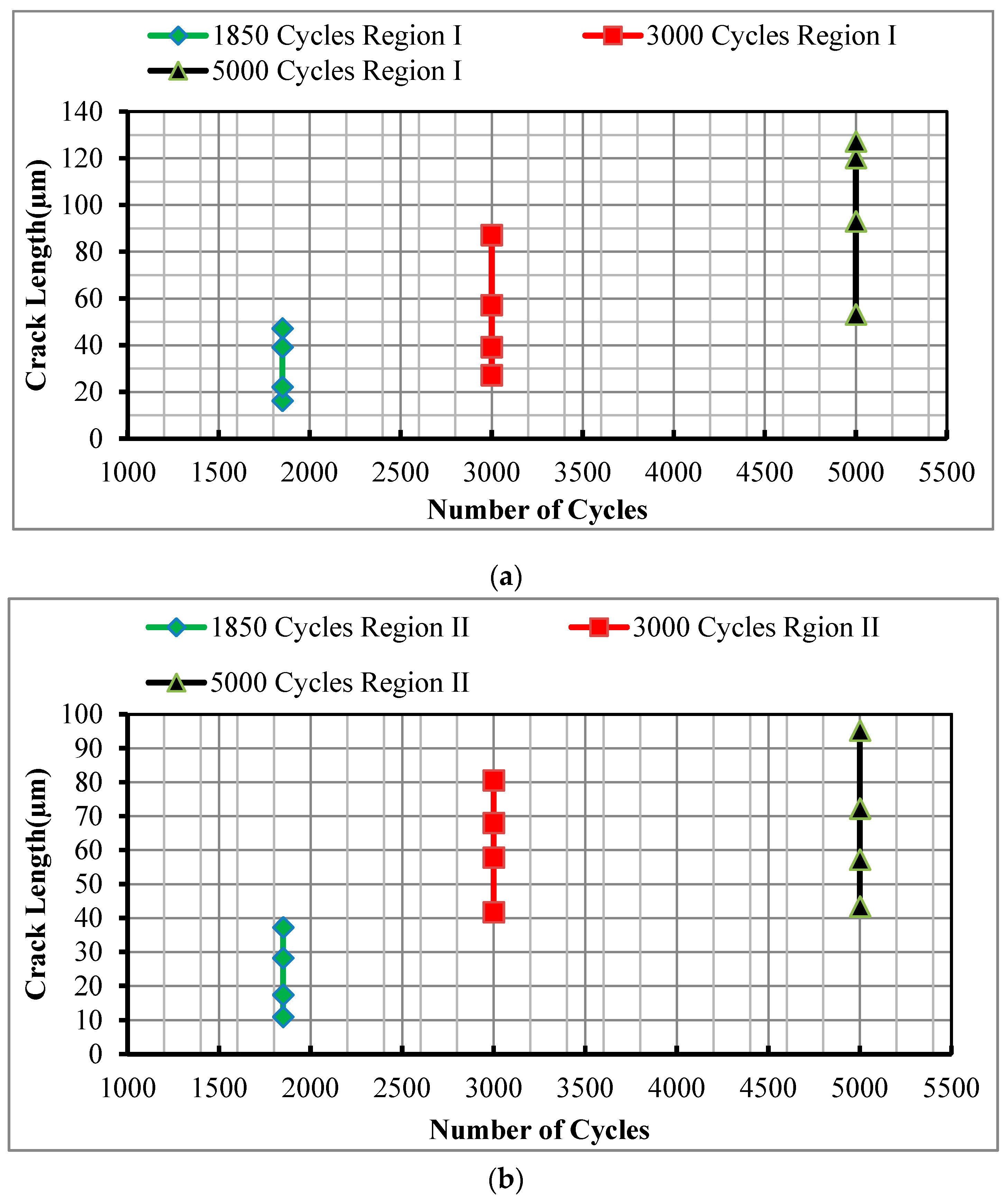
Figure 4.
Oxygen distribution within the crack area of Region I and Region II in thermally worn H13 samples at 1850 cycles (a,b); 3000 cycles (c,d); 5000 cycles (e,f), respectively.
Figure 4.
Oxygen distribution within the crack area of Region I and Region II in thermally worn H13 samples at 1850 cycles (a,b); 3000 cycles (c,d); 5000 cycles (e,f), respectively.

Figure 5.
Concentration of oxygen along the surface depth from Region I and II in thermally worn H13 samples at (a) 1850 cycles; (b) 3000 cycles; and, (c) 5000 cycles.
Figure 5.
Concentration of oxygen along the surface depth from Region I and II in thermally worn H13 samples at (a) 1850 cycles; (b) 3000 cycles; and, (c) 5000 cycles.

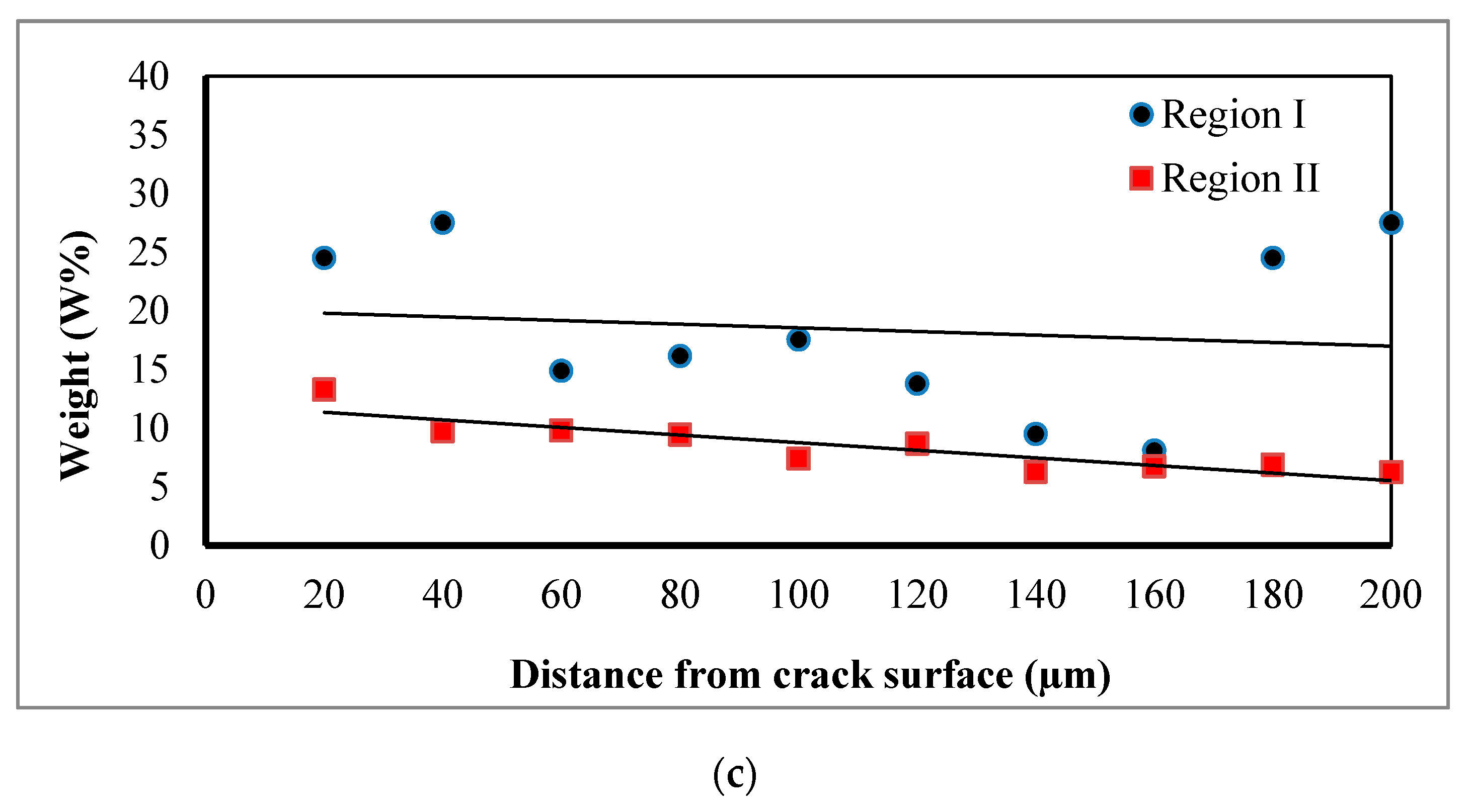
Figure 6.
Comparison of Region I and II hardness properties along the surface depth a thermally worn AISI H13 steel sample.
Figure 6.
Comparison of Region I and II hardness properties along the surface depth a thermally worn AISI H13 steel sample.


Table 1.
Chemical composition of AISI H13 tool steel and A356 aluminium.
| H13 Tool Steel | |||||||
| Element | C | Si | Mn | Cr | Mo | V | W |
| wt % | 0.51 | 1.26 | 0.413 | 5.5 | 1.52 | 1.0 | 0.02 |
| Al 356 | |||||||
| Element | Cu | Mg | Mn | Si | Zn | Ti | Fe |
| wt % | 0.25 | 0.45 | 0.35 | 7.5 | 0.35 | 0.25 | 0.2 |
© 2017 by the authors. Licensee MDPI, Basel, Switzerland. This article is an open access article distributed under the terms and conditions of the Creative Commons Attribution (CC BY) license (http://creativecommons.org/licenses/by/4.0/).
Share and Cite
MDPI and ACS Style
Abdulhadi, H.A.; Ahmad, S.N.A.S.; Ismail, I.; Ishak, M.; Mohammed, G.R. Thermally-Induced Crack Evaluation in H13 Tool Steel. Metals 2017, 7, 475. https://doi.org/10.3390/met7110475
AMA Style
Abdulhadi HA, Ahmad SNAS, Ismail I, Ishak M, Mohammed GR. Thermally-Induced Crack Evaluation in H13 Tool Steel. Metals. 2017; 7(11):475. https://doi.org/10.3390/met7110475
Chicago/Turabian StyleAbdulhadi, Hassan Abdulrssoul, Syarifah Nur Aqida Syed Ahmad, Izwan Ismail, Mahadzir Ishak, and Ghusoon Ridha Mohammed. 2017. "Thermally-Induced Crack Evaluation in H13 Tool Steel" Metals 7, no. 11: 475. https://doi.org/10.3390/met7110475
Note that from the first issue of 2016, this journal uses article numbers instead of page numbers. See further details here.