The Influence of the Powder Stream on High-Deposition-Rate Laser Metal Deposition with Inconel 718
by
Chongliang Zhong
1,*, 
Norbert Pirch
1,
Andres Gasser
1,
Reinhart Poprawe
1,2 and
Johannes Henrich Schleifenbaum
1,3 1
Fraunhofer Institute for Laser Technology ILT, Steinbachstr. 15, 52074 Aachen, Germany
2
Chair for Laser Technology, RWTH Aachen University, Steinbachstr. 15, 52074 Aachen, Germany
3
Chair for Digital Additive Production DAP, RWTH Aachen University, Steinbachstr. 15, 52074 Aachen, Germany
*
Author to whom correspondence should be addressed.
Metals 2017, 7(10), 443; https://doi.org/10.3390/met7100443
Submission received: 1 September 2017
/
Revised: 10 October 2017
/
Accepted: 12 October 2017
/
Published: 20 October 2017
Abstract
:For the purpose of improving the productivity of laser metal deposition (LMD), the focus of current research is set on increasing the deposition rate, in order to develop high-deposition-rate LMD (HDR-LMD). The presented work studies the effects of the powder stream on HDR-LMD with Inconel 718. Experiments have been designed and conducted by using different powder feeding nozzles—a three-jet and a coaxial powder feeding nozzle—since the powder stream is mainly determined by the geometry of the powder feeding nozzle. After the deposition trials, metallographic analysis of the samples has been performed. The laser intensity distribution (LID) and the powder stream intensity distribution (PID) have been characterized, based on which the processes have been simulated. Finally, for verifying and correcting the used models for the simulation, the simulated results have been compared with the experimental results. Through the conducted work, suitable boundary conditions for simulating the process with different powder streams has been determined, and the effects of the powder stream on the process have also been determined. For a LMD process with a three-jet nozzle a substantial part of the powder particles that hit the melt pool surface are rebounded; for a LMD process with a coaxial nozzle almost all the particles are caught in the melt pool. This is due to the different particle velocities achieved with the two different nozzles. Moreover, the powder stream affects the heat exchange between the heated particles and the melt pool: a surface boundary condition applies for a powder stream with lower particle velocities, in the experiment provided by a three-jet nozzle, and a volumetric boundary condition applies for a powder stream with higher particle velocities, provided by a coaxial nozzle.
1. Introduction
Laser metal deposition (LMD)—also known as direct metal deposition (DMD), direct laser deposition (DLD), and laser engineered net shaping (LENS)—is one of the laser additive manufacturing (LAM) processes. In LMD, a laser beam is used as the power source to generate a melt pool on the base material, normally a metal substrate, and to melt the metal powder that is injected by a powder nozzle into the melt pool. The powder feeding nozzle and the laser optic together form the LMD processing head. With the relative movement between the processing head and the working table, the melt pool solidifies and a single track is deposited. A layer is formed by the overlapping of single tracks, and a 3D structure can be built up layer by layer.
Due to the principle of LMD, the material waste can be much lower than that of conventional manufacturing methods, such as turning or milling from solid, in which material is removed to create the desired geometry.
Moreover, LMD has advantages in comparison to other deposition welding processes, such as the defined low heat input, which enables an accurate control of solidification. In addition, due to the small heat affected zone (HAZ) and non-equilibrium rapid solidification, a fine microstructure can be obtained, leading to improved mechanical properties.
The applications of LMD in industry have been growing in recent years [1,2,3,4]. For its development, research nowadays involves all kinds of areas, such as process optimization [5,6,7,8,9], modelling/simulation [10,11,12,13,14], and material microstructure and mechanical properties [15,16,17,18,19].
Inconel 718 (IN718) is a nickel-based super-alloy. It has high strength, high wear and creep resistance at elevated temperatures, and is very widely used in aerospace and energy industries [20,21]. LMD can be used to process IN718, for example to repair or to additive manufacture components in turbo engines, which brings high economic benefits. Thus, investigations on LMD for IN718 have been attracted more and more attention [22,23,24,25]. One research focus is to develop high-deposition-rate laser metal deposition (HDR-LMD) for IN718 [26,27,28,29] in order to improve productivity. The deposition rate of conventional LMD for IN718 is lower than 0.5 kg/h; in comparison, the deposition rate for HDR-LMD is higher than 2 kg/h.
HDR-LMD with IN718 has been intensively investigated by the author. Firstly, a novel method for establishing a process window for HDR-LMD of IN718 [26] has been developed and methods for the reduction of porosity [27] have been presented. Secondly, investigations of the effects of main process parameters on the deposition properties have been conducted [28]. In addition, microstructures and tensile properties of IN718 formed by HDR-LMD have been characterized [29]. Based on the results of these previous studies, it is found that the powder stream significantly affects the track geometry and dilution properties of the cladded track, which are crucial factors that must be considered for process development. Therefore, the current work has been conducted to study the effects of the powder stream on HDR-LMD with IN718.
For obtaining different powder streams, a coaxial and a three-jet powder feeding nozzle have been used, since the powder stream is mainly determined by the powder feeding system; to ensure the parallelism, the experiments have been conducted under identical conditions. In order to simulate the processes, the laser beam and the powder streams have been characterized by using the following parameters: laser intensity distribution (LID) for the laser beam and powder intensity distribution (PID), and particle velocity for the powder stream.
2. Materials and Methods
Gas atomized (GA) IN718 powder has been used, with a grain size distribution in the range of 45 to 90 µm. The chemical composition for the main elements of the used powder has been measured using the ICP (inductively-coupled plasma spectroscopy) method, and the results are shown in Table 1.
The powder has been additionally analysed by using an optical microscope (OM, Zeiss, Jena, Germany) and scanning electron microscope (SEM, Zeiss, Jena, Germany). An optical micrograph that shows the metallographic prepared cross-sections, as well as a SEM micrograph that shows the morphology of the powder, are presented in Figure 1.
As shown in Figure 1 there exists a large fraction of powder particles that feature satellites—the small particles which adhere on the large particles. Additionally, a large number of irregularly-shaped particles and particles with enclosed pores can be observed. IN718 has been used as the base material for the experiments.
The experimental setup consists mainly of a diode laser source with maximal 12 kW output, a collimator, a zoom optic, a powder feeder and a powder feeding nozzle. The high power diode laser is linked via a glass fiber to the laser optic. The movement of the lenses in the zoom optic and the tool axis are controlled by the NC-control of a four-axis tool machine. A three-jet and a coaxial powder feeding nozzle are used for the experiments.
The three-jet nozzle and the coaxial nozzle (Fraunhofer ILT, Aachen, Germany), which are two commonly used powder nozzles for coaxial powder feeding, have different powder feeding mechanisms, so that significantly different powder streams can be obtained by using them. Photos for comparing these two nozzles, showing their different powder-gas jets with approx. 2.7 kg/h powder feeding rate, are presented in Figure 2.
Experiments using these two nozzles have been conducted under identical experimental conditions. The main process parameters are as follows: powder mass flow rate , laser power , scanning speed and laser spot diameter . The offset distances are dependent on the focus position of the nozzles, and they are 12 and 14 mm for the three-jet nozzle and the coaxial nozzle, respectively.
3. Results
3.1. Powder Intensity Distribution
The powder particle trajectories are calculated by a statistical model which is based and cross-checked on the experimental input of the particle intensity measurement system, which is developed by Fraunhofer Institute for Laser Technology ILT [30]. The results that show the particle intensity distributions (PID) on the working plane are presented in Figure 3.
It can be seen in Figure 3 that the PID for both nozzles are similar. Nevertheless, the three-jet nozzle is slightly steeper, which indicates that the PID should not be the main reason for different track heights, powder efficiency, and dilution geometries. However, according to this result, one would expect the three-jet nozzle has a higher powder efficiency due to its lower extension of the PID on the working plane compared to that of the coaxial nozzle.
3.2. Laser Intensity Distribution
The measurement of the laser intensity distribution (LID) is done with a PRIMES Focus Monitor [31]: it measures the spatial power intensity distribution in the focus range of the processing optic, based on which the system calculates the beam radius, the focus position in the space, as well as the beam propagation ratio K or—respectively—the beam propagation factor M2. The LID of the used diode laser on the working plane and the super Gauss fit [32] of it are shown in Figure 4.
3.3. Experimental Results
The deposited tracks with both nozzles appear similar. Two randomly-selected cross-sectioned and etched tracks deposited respectively by the three-jet nozzle and the coaxial nozzle are shown in Figure 5.
By comparing these two cross-sections shown in Figure 5 significant differences can be seen. In order to ensure the statistical reliability, three cross-sections of different positions from each track have been analyzed. This analysis shows the following results: the track height of the coaxial nozzle is about 18% higher than that of the three-jet nozzle; the dilution of three-jet nozzle is approx. one-fourth of that of the coaxial nozzle; the area of the track processed with the three-jet nozzle is approx. 2.93 mm2, and that of the coaxial nozzle, 3.35 mm2.
The deposition rate can be calculated by using the following formula:
with:
- : deposition rate;
- : scanning speed;
- : mean cross-sectional area; and
- : density of IN718.
The calculated deposition rates for the three-jet nozzle and the coaxial nozzle are 2.173 and 2.485 kg/h, respectively.
The powder efficiency can, therefore, be calculated by dividing the deposition rate by the powder feeding rate. The calculated powder efficiency for the three-jet and the coaxial nozzle are 80.5% and 92%, respectively.
This result is just the opposite of the expectation drawn from the PID analysis result. Since the experimental conditions are identical, the different powder deposition rate and powder efficiency must be caused by the different powder streams that are mainly determined by the powder feeding nozzles. In the following section, the effects of powder stream will be identified by simulating the processes.
4. Process Simulation
4.1. HDR-LMD with a Three-Jet Nozzle
A three-dimensional time-dependent finite element model for LMD with coaxial powder feeding is used for simulating the process with the three-jet nozzle [30]. The used model encompasses the powder stream, its interaction with the laser radiation, and the melt pool. Based on this model, the temperature distribution and the track geometry have been calculated and the results are shown in Figure 6.
As can be seen in Figure 6, the temperature field exhibits a sickle-like distribution in the interaction zone: there is an area where the process temperature exceeds the evaporating temperature of IN718; there is one area in the middle of the sickle distribution where a temperature reduction can be observed. This is the consequence of the laser radiation being shadowed by the powder particles, which can be seen in in the following discussions.
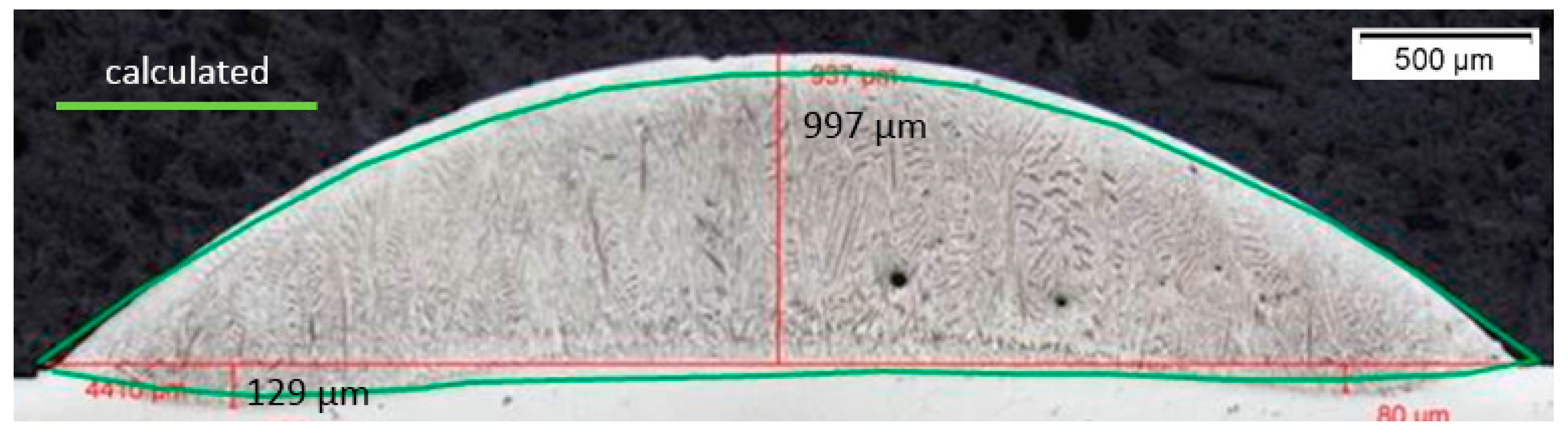
The result for the comparison between the calculated and the metallographic prepared cross-section of the deposited track with the three-jet nozzle is shown in Figure 7.
Figure 7 shows an excellent agreement of the experimental and the computed results, which indicates that the used model is suitable to simulate the process.
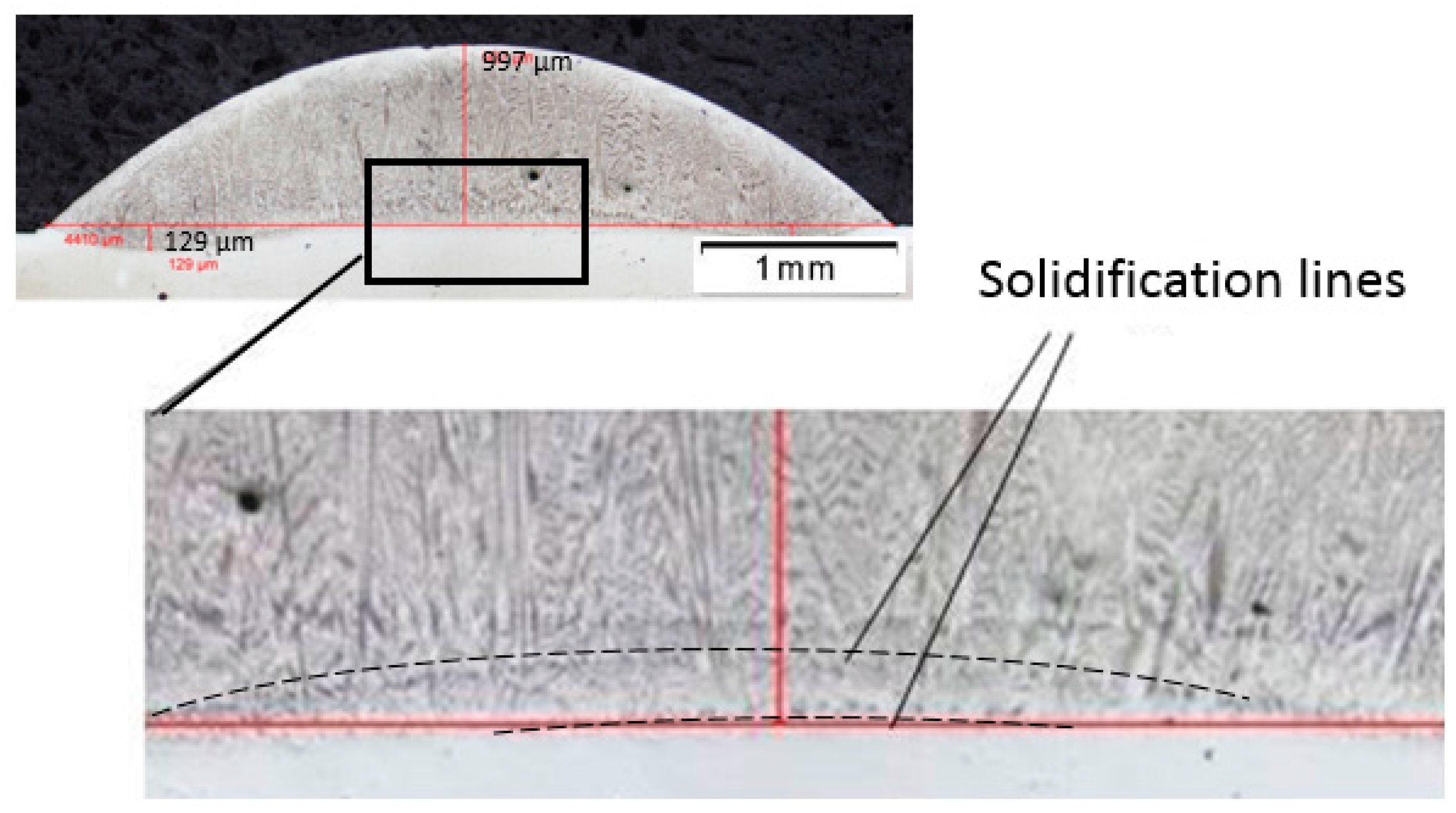
One optical micrograph with higher resolution that shows the interface of the track and the substrate is presented in Figure 8, where the solidification line can be identified.
In Figure 8, two solidification lines in the middle of the track can be seen, which should be caused by a repeated melting of an area that has been solidified before.
Further simulation has reproduced this observed detail in the microstructure: the solid/liquid interface shows a local maximum in the area beneath the sickle-like temperature distribution on the melt pool surface, as shown in Figure 9.
This local maximum on the solid/liquid interface, shown in Figure 9, indicates that a part of the already-solidified region is melted again, and the following solidification causes the second solidification line.
The transmitted LID projected onto the track geometry shows that the track width is approximately the same as the beam diameter, as can be seen in Figure 10.
This result explains the sickle-like temperature distribution observed in Figure 6.
According to the simulated and experimental results, 98% of the particles hit the melt pool surface (Figure 10b), although the measured powder efficiency for the three-jet nozzle is about 80.5%. Therefore, a substantial part of the powder particles that hit the melt pool surface must have been rebounded, as has been reported by Tan [33]. This result contradicts the general belief that all particles that hit the melt pool surface are incorporated into it. A more detailed discussion is given in Section 4.2.
4.2. Particle Adsorption
Since the mechanism for particle rebounding is not well understood, the powder efficiency needs to be considered in the model, similarly to the absorptivity of the laser radiation.
Particle adsorption for LMD has been investigated by de Hosson et al. [34] and they concluded that adsorption occurs if the kinetic energy is higher than the interfacial energy for a complete wetting. Hosson derived a formula for the penetration depth by integration of the momentum balance for spherical particles under consideration of the Stokes force and the buoyancy force. The theoretical predictions concerning the penetration depth for SiC particles in the TiAl6V4 melt have been experimentally verified. Hosson achieved penetration depths up to 1.4 mm, whereby the particles have to exceed a velocity limit of about 2 m/s to avoid rebounding from the melt.
The median particle velocity can be derived from the average particle intensity in a lighted layer, the average particle diameter, the specific intensity and the powder mass flow. The median particle velocity determined for the coaxial nozzle is 11.28 m/s, and for the three-jet nozzle 3.76 m/s. These can be put into the following formula from Hosson:
with:
- : particle penetration depth;
- : reduced particle velocity;
- : a constant that is decided by , , and ;
- : dynamic viscosity;
- : particle radius; and
- : density.
In order for the particles to penetrate the melt, they must overcome the interfacial forces. The energy necessary for this is taken from the kinetic energy; what still remains is the reduced particle velocity . This is then the starting condition for a differential equation for a spherical particle which has already been immersed in the melt and whose velocity is reduced by the Stokes frictional force and buoyancy force. is a constant which is derived from the integration of the differential equation and is determined by the boundary conditions. Under identical experimental conditions, IN718 powder fed by three-jet and coaxial nozzles have the same kinetic energy loss for the complete wetting of the particles. With the estimation that has been made, the expected penetration depth for the three-jet nozzle and the coaxial nozzle are 26 and 500 μm, respectively. For the given particle diameters and a theoretical continuum (not particle-resolved modeling), the 26 µm penetration depth in relation to the melting depth means a surface source.
For the coaxial nozzle, the boundary condition for heat exchange between the heated particles and the melt pool used in the model for the three-jet nozzle needs to be changed from a surface boundary condition to a volumetric boundary condition.
4.3. HDR-LMD with a Coaxial Nozzle
Based on the adapted model, with the volumetric boundary condition for the process with the coaxial nozzle, the temperature distribution and the track geometry are calculated, and the results are shown in Figure 11.
In Figure 11a, the simulated temperature distribution shows that there is a large region in the beam interaction zone where the temperature is higher than the evaporating temperature of IN718. In addition, as can be seen in Figure 11b, the dilution profile in the y-z view is not symmetric, and it shows a local maximum located away from the middle of the track, which must be caused by the non-symmetric PID.
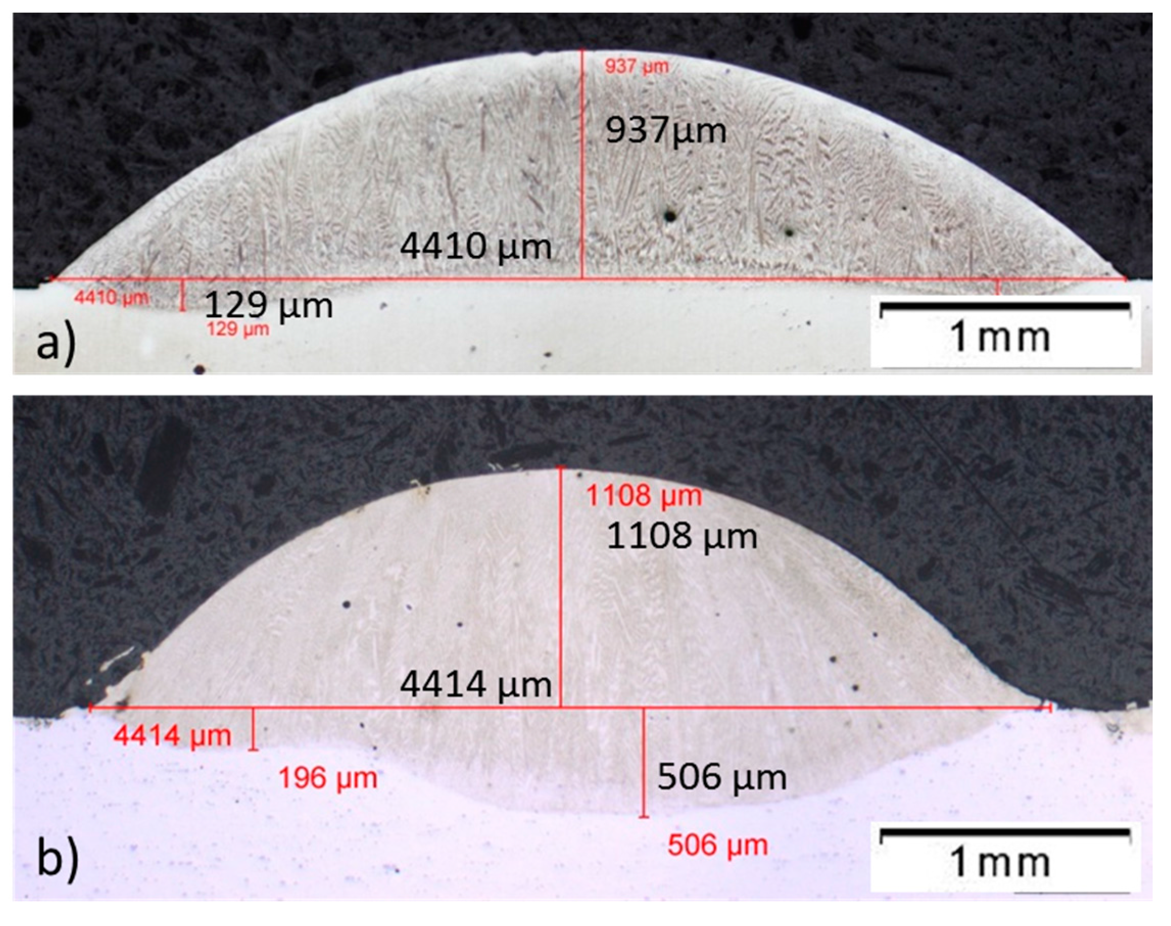
Figure 12 shows two metallographic prepared cross-sections of the track deposited with the coaxial nozzle.
As is shown in Figure 12a, the calculated dilution profile shown in Figure 11b fits well with the metallographic prepared cross-section at this position—this proves that the adapted model is suitable and effective for simulating the process with the coaxial nozzle.
The cross-section shown in Figure 12b illustrates that the local maximum has shifted to the other side, which means the PID is not stationary and probably time-dependent.
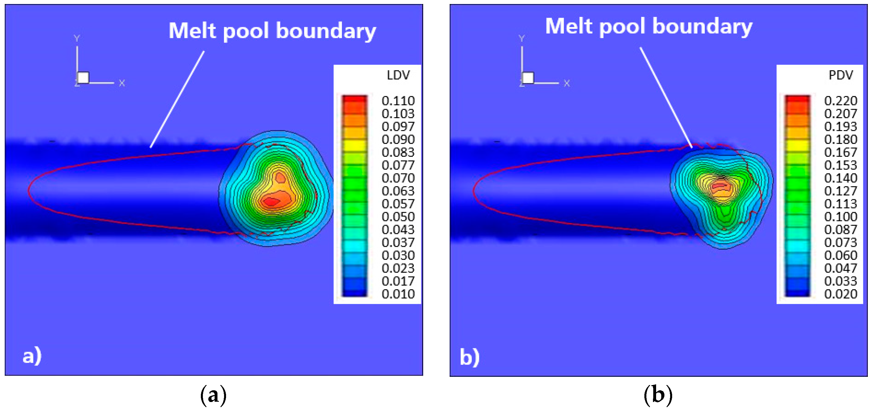
The transmitted LID and PID for the coaxial nozzle projected onto the track geometry are shown in Figure 13.
It can be seen from Figure 13a that the transmitted LID for the coaxial nozzle projected onto the track geometry shows that the track width is approximately the same as the beam diameter. As shown in Figure 13b, for the process with the coaxial nozzle, 94% of the particles hit the melt pool surface, and the calculated powder efficiency based on the experimental results is 92% (see Section 3.3). This means that almost all the particles that hit the melt pool surface have been caught and absorbed, which agrees well with the model from Lin et al. [35] for particle catchment.
The melt pool surface shows a large region where the temperature is higher than the evaporating temperature of IN718, and thereby the interfacial energy for wetting the particles vanishes, which is probably the physical reason for the high particle efficiency.
5. Conclusions
In this work we have investigated the effects of the powder stream on high-deposition-rate laser metal deposition (HDR-LMD) with Inconel 718 (IN718).
Initially, LMD experiments with a coaxial nozzle and a three-jet nozzle under identical experimental conditions were performed. The used nozzles deliver different powder streams according to their different feeding principles. Afterwards, metallographic analysis was carried out: the cross-sections of the deposited single tracks were analyzed and the results have been evaluated. The laser beam and the powder streams have been characterized using the data acquired from a PRIMES Focus Monitor and an ILT particle intensity measurement system, respectively. Furtherly, the characterized laser beam and powder streams were used to simulate the processes. In correlation with the experimental results, suitable models for simulating processes with different powder streams have been identified, and the mechanism of the effects of the powder stream on HDR LMD with IN718 have been found. Based on the results, the following conclusions can be drawn:
- With the three-jet nozzle, a substantial part of the powder particles that hit the melt pool surface are rebounded; with the coaxial nozzle, almost all the particles that hit the melt pool surface have been caught and absorbed.
- Different particle velocity must be the main reason for this result since, with similar PID, the particle velocity determines the penetration depth of the powder particle into the melt pool.
- Due to the different penetration depth, the model used for simulating the processes with different power streams should be adapted, using different boundary conditions.
- The powder stream affects the heat exchange between the heated particles and the melt pool: a surface boundary condition applies for a powder stream with lower particle velocities, in this experiment, provided by a three-jet nozzle, and a volumetric boundary condition applies for a powder stream with higher particle velocities, provided here by a coaxial nozzle.
Acknowledgments
All presented investigations were conducted in the context of the Collaborative Research Centre SFB1120 “Precision Melt Engineering” at RWTH Aachen University and funded by the German Research Foundation (DFG). For the sponsorship and the support we wish to express our sincere gratitude.
Author Contributions
The experimental part was conducted by Chongliang Zhong and the simulation part by Norbert Pirch. The manuscript was corrected by Andres Gasser. Reinhart Poprawe and Johannes Henrich Schleifenbaum supervised the whole work.
Conflicts of Interest
The authors declare no conflict of interest.
References
- Singh, A.; Ramakrishnan, A.; Dinda, G.P. Direct Laser Metal Deposition of Eutectic Al-Si Alloy for Automotive Applications. In Proceedings of the TMS 2017, 146th Annual Meeting & Exhibition Supplemental Proceedings, San Diego, CA, USA, 26 February–2 March 2017; pp. 71–80. [Google Scholar]
- Payne, G.; Ahmad, A.; Fitzpatrick, S.; Xirouchakis, P.; Ion, W.; Wilson, M. Remanufacturing H13 steel moulds and dies using laser metal deposition. In Advances in Manufacturing Technology XXX; IOS Press: Amsterdam, The Netherlands, 2016; p. 93. [Google Scholar]
- Petrat, T.; Graf, B.; Gumenyuk, A.; Rethmeier, M. Laser metal deposition as repair technology for a gas turbine burner made of Inconel 718. Phys. Proc. 2016, 83, 761–768. [Google Scholar] [CrossRef]
- Yilmaz, O.; Ugla, A.A. Shaped metal deposition technique in additive manufacturing: A review. Proc. Inst. Mech. Eng. B J. Eng. Manuf. 2016, 230, 1781–1798. [Google Scholar] [CrossRef]
- Boisselier, D.; Sankaré, S.; Engel, T. Improvement of the Laser Direct Metal Deposition Process in 5-axis Configuration. Phys. Proc. 2014, 56, 239–249. [Google Scholar] [CrossRef]
- Mahamood, R.M.; Akinlabi, E.T. Laser metal deposition of functionally graded Ti6Al4V/TiC. Mater. Des. 2015, 84, 402–410. [Google Scholar] [CrossRef]
- Shamsaei, N.; Yadollahi, A.; Bian, L.; Thompson, S.M. An overview of Direct Laser Deposition for additive manufacturing; Part II: Mechanical behavior, process parameter optimization and control. Addit. Manuf. 2015, 8, 12–35. [Google Scholar] [CrossRef]
- Ponche, R.; Kerbrat, O.; Mognol, P.; Hascoet, J.-Y. A novel methodology of design for Additive Manufacturing applied to Additive Laser Manufacturing process. Robot. Comput. Integr. Manuf. 2014, 30, 389–398. [Google Scholar] [CrossRef]
- Calleja, A.; Tabernero, I.; Fernández, A.; Celaya, A.; Lamikiz, A.; de Lacalle, L.L. Improvement of strategies and parameters for multi-axis laser cladding operations. Opt. Lasers Eng. 2014, 56, 113–120. [Google Scholar] [CrossRef]
- Hofman, J.T.; Lange, D.F.; de Pathiraj, B.; Meijer, J. FEM modeling and experimental verification for dilution control in laser cladding. J. Mater. Process. Technol. 2011, 2, 187–196. [Google Scholar] [CrossRef]
- Angelastro, A.; Campanelli, S.L.; Casalino, G.; Ludovico, A.D.; Ferrara, S. A methodology for optimization of the Direct Laser Metal Deposition process. Key Eng. Mater. 2011, 473, 75–82. [Google Scholar] [CrossRef]
- Farahmand, P.; Kovacevic, R. An experimental–numerical investigation of heat distribution and stress field in single- and multi-track laser cladding by a high-power direct diode laser. Opt. Laser Technol. 2014, 63, 154–168. [Google Scholar] [CrossRef]
- Tabernero, I.; Lamikiz, A.; Martinez, S.; Ukar, E.; De Lacalle, L.L. Modelling of energy attenuation due to powder flow-laser beam interaction during laser cladding process. J. Mater. Process. Technol. 2012, 212, 516–522. [Google Scholar] [CrossRef]
- Kamara, A.M.; Marimuthu, S.; Li, L. Finite Element Modeling of Microstructure in Laser-Deposited Multiple Layer Inconel 718 Parts. Mater. Manuf. Process. 2014, 29, 1245–1252. [Google Scholar] [CrossRef]
- Hong, C.; Gu, D.; Dai, D.; Gasser, A.; Weisheit, A.; Kelbassa, I.; Zhong, M.; Poprawe, R. Laser metal deposition of TiC/Inconel 718 composites with tailored interfacial microstructures. Opt. Laser Technol. 2013, 54, 98–109. [Google Scholar] [CrossRef]
- Sun, G.; Bhattacharya, S.; Dinda, G.P.; Dasguptac, A.; Mazumder, J. Microstructure evolution during laser-aided direct metal deposition of alloy tool steel. Scr. Mater. 2011, 64, 454–457. [Google Scholar] [CrossRef]
- Lu, Y.; Tang, H.B.; Fang, Y.L.; Liu, D.; Wang, H.M. Microstructure evolution of sub-critical annealed laser deposited Ti–6Al–4V alloy. Mater. Des. 2012, 37, 56–63. [Google Scholar] [CrossRef]
- Raju, R.; Duraiselvam, M.; Petley, V.; Verma, S.; Rajendran, R. Microstructural and mechanical characterization of Ti6Al4V refurbished parts obtained by laser metal deposition. Mater. Sci. Eng. A 2015, 643, 64–71. [Google Scholar] [CrossRef]
- Ren, H.-S.; Tian, X.-J.; Liu, D.; Liu, J.; Wang, H.-M. Microstructural evolution and mechanical properties of laser melting deposited Ti–6.5Al–3.5Mo–1.5Zr–0.3Si titanium alloy. Trans. Nonferrous Met. Soc. China 2015, 25, 1856–1864. [Google Scholar] [CrossRef]
- Anderson, M.; Patwa, R.; Shin, Y.C. Laser-assisted machining of Inconel 718 with an economic analysis. Int. J. Mach. Tools Manuf. 2006, 46, 1879–1891. [Google Scholar] [CrossRef]
- Rahman, M.; Seah, W.; Teo, T.T. The machinability of inconel 718. J. Mater. Process. Technol. 1997, 63, 199–204. [Google Scholar] [CrossRef]
- Parimi, L.L.; Ravi, G.A.; Clark, D.; Attallah, M.M. Microstructural and texture development in direct laser fabricated IN718. Mater. Charact. 2014, 89, 102–111. [Google Scholar] [CrossRef]
- Tabernero, I.; Lamikiz, A.; Martínez, S.; Ukar, E.; Figuera, J. Evaluation of the mechanical properties of Inconel 718 components built by laser cladding. Int. J. Mach. Tools Manuf. 2011, 51, 465–470. [Google Scholar] [CrossRef]
- Lambarri, J.; Leunda, J.; Navas, V.G.; Soriano, C.; Sanz, C. Microstructural and tensile characterization of Inconel 718 laser coatings for aeronautic components. Opt. Lasers Eng. 2013, 51, 813–821. [Google Scholar] [CrossRef]
- Liu, F.; Lin, X.; Leng, H.; Cao, J.; Liu, Q.; Huang, C.; Huang, W. Microstructural changes in a laser solid forming Inconel 718 superalloy thin wall in the deposition direction. Opt. Laser Technol. 2013, 45, 330–335. [Google Scholar] [CrossRef]
- Zhong, C.; Gasser, A.; Kittel, J.; Schopphoven, T.; Pirch, N. Study of process window development for high deposition-rate laser material deposition by using mixed processing parameters. J. Laser Appl. 2015, 27, 032008. [Google Scholar] [CrossRef]
- Zhong, C.; Gasser, A.; Schopphoven, T.; Poprawe, R. Experimental study of porosity reduction in high deposition-rate Laser Material Deposition. Opt. Laser Technol. 2015, 75, 87–92. [Google Scholar] [CrossRef]
- Zhong, C.; Biermann, T.; Gasser, A.; Poprawe, R. Experimental study of effects of main process parameters on porosity, track geometry, deposition rate, and powder efficiency for high deposition rate laser metal deposition. J. Laser Appl. 2015, 27, 042003. [Google Scholar] [CrossRef]
- Zhong, C.; Gasser, A.; Kittel, J.; Fu, J.; Ding, Y.; Poprawe, R. Microstructures and tensile properties of Inconel 718 formed by high deposition-rate laser metal deposition. J. Laser Appl. 2016, 28, 022010. [Google Scholar] [CrossRef]
- Pirch, N.; Linnenbrink, S.; Gasser, A.; Wissenbach, K.; Poprawe, R. Analysis of track formation during laser metal deposition. J. Laser Appl. 2016, 29, 022506. [Google Scholar] [CrossRef]
- FocusMonitor FM+. PRIMES. Available online: https://www.primes.de/en/products/beam-distribution/focus-measurement/focusmonitor-fm.html (accessed on 9 October 2017).
- Pirch, N.; Zielinski, J. Spatial resolved laser beam diagnostics for material processing. In Proceedings of the 6th Primes Workshop, Darmstadt, Germany, 10–11 September 2014. [Google Scholar]
- Tan, H.; Hu, G.; Zhang, F.; Fan, W.; Hou, W.; Huang, W. Formation mechanism of adhering powder and improvement of the surface quality during laser solid forming. Int. J. Adv. Manuf. Technol. 2016, 86, 1329–1338. [Google Scholar] [CrossRef]
- Vreeling, J.A.; Ocelík, V.; Pei, Y.T.; van Agterveld, D.T.; De Hosson, J.T. Laser melt injection in aluminum alloys: On the role of the oxide skin. Acta Mater. 2000, 48, 4225–4233. [Google Scholar] [CrossRef]
- Lin, J.M. A simple model of powder catchment in coaxial laser cladding. Opt. Laser Technol. 1999, 31, 233–238. [Google Scholar] [CrossRef]
Figure 1.
(a) Metallographic prepared cross-sections and (b) scanning electron microscope (SEM) micrograph of the used IN718 powder.
Figure 1.
(a) Metallographic prepared cross-sections and (b) scanning electron microscope (SEM) micrograph of the used IN718 powder.
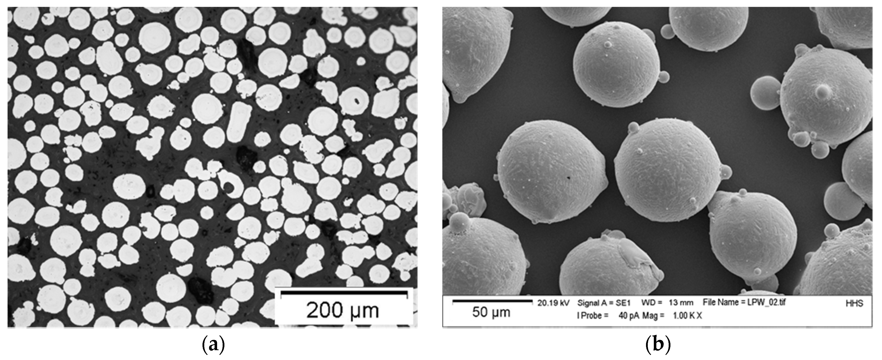
Figure 2.
Powder-gas-jets of the three-jet nozzle (a) and the coaxial nozzle (b) with a powder feeding rate of approx. 2.7 kg/h.
Figure 2.
Powder-gas-jets of the three-jet nozzle (a) and the coaxial nozzle (b) with a powder feeding rate of approx. 2.7 kg/h.

Figure 3.
3D colored pictures that show the PIDs: three-jet nozzle (a); coaxial nozzle (b); and the overlap of them (c). The PID on the working plane of the three-jet nozzle (a) and the coaxial nozzle (b) are superimposed in transparency mode with different colors in the two side views (c), and the used powder mass flow rate is approx. 2.7 kg/h.
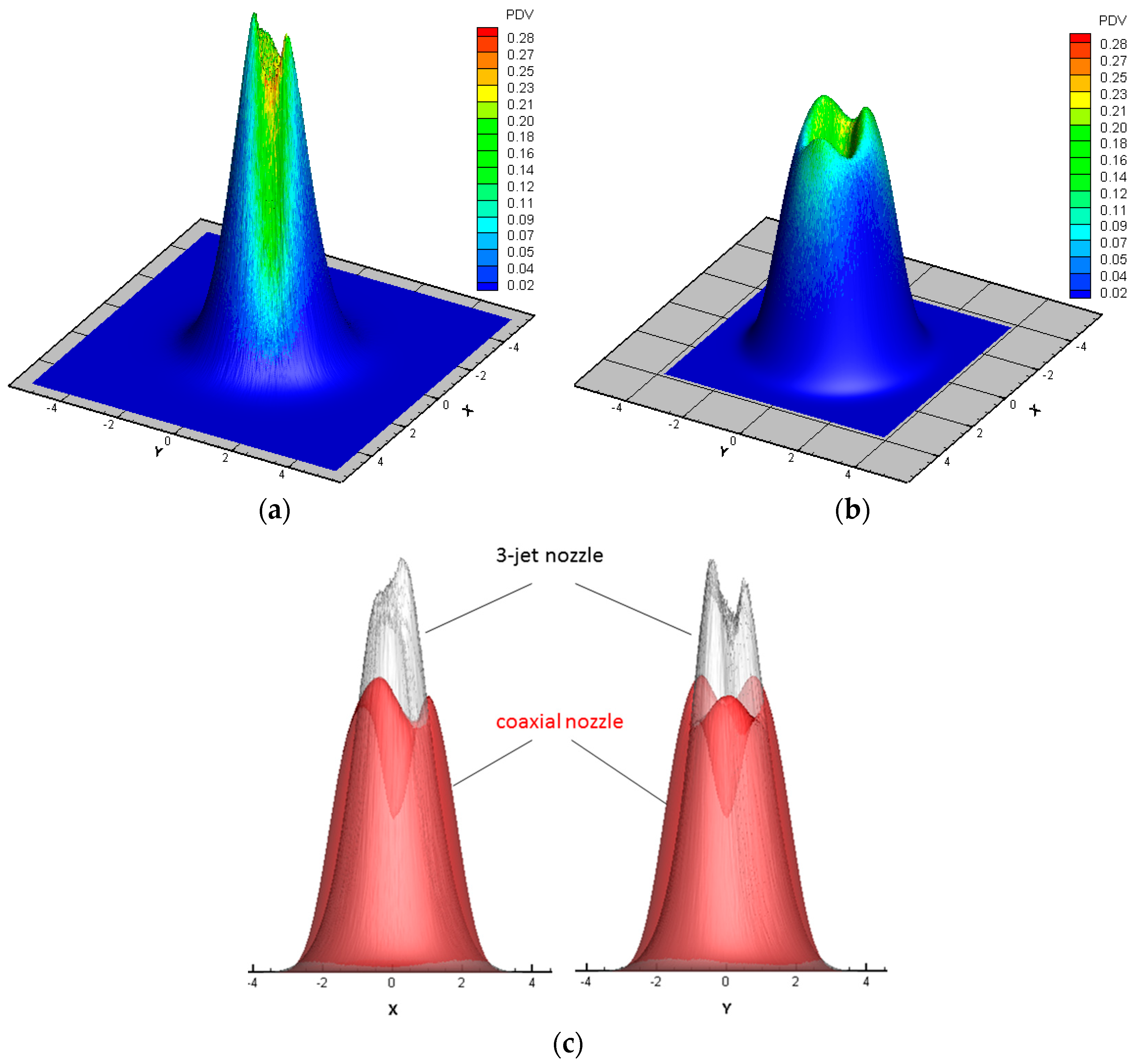
Figure 4.
(a) LID of the used 12 kW diode laser on the working plane; (b) approximation by a Super Gauss fit using an in-house software.
Figure 4.
(a) LID of the used 12 kW diode laser on the working plane; (b) approximation by a Super Gauss fit using an in-house software.
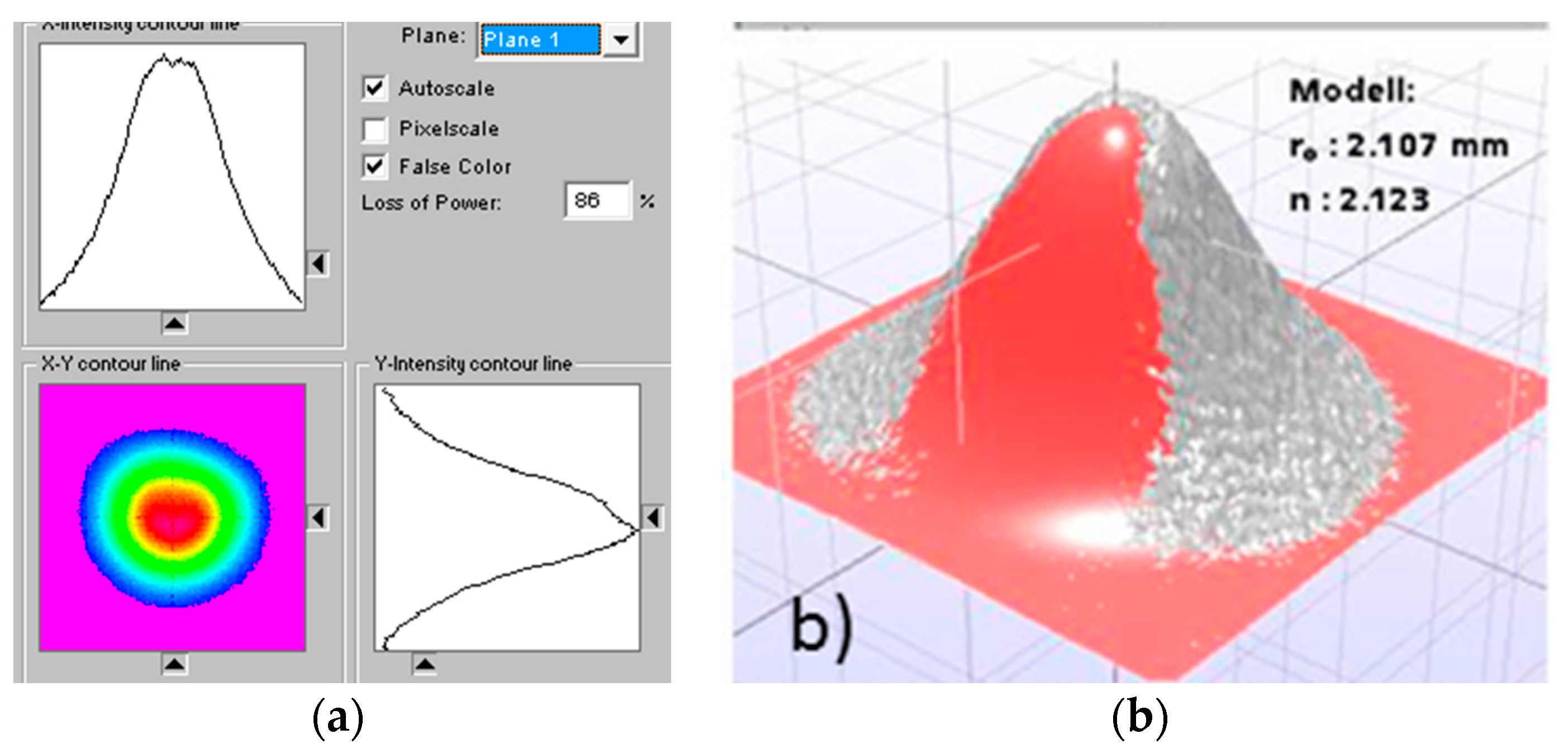
Figure 5.
Metallographic prepared cross-sections of a track processed with: (a) three-jet nozzle; and (b) coaxial nozzle.
Figure 5.
Metallographic prepared cross-sections of a track processed with: (a) three-jet nozzle; and (b) coaxial nozzle.

Figure 6.
Temperature distribution and track geometry for the three-jet nozzle.
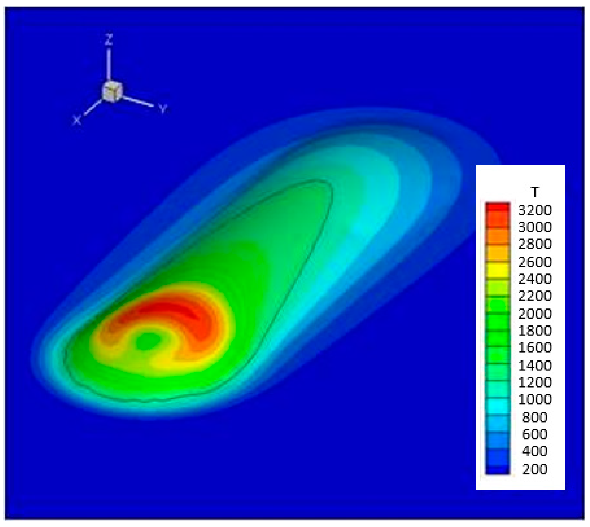
Figure 7.
Comparison of the calculated cross-section with a metallographic prepared cross-section of a track deposited with the three-jet nozzle.
Figure 7.
Comparison of the calculated cross-section with a metallographic prepared cross-section of a track deposited with the three-jet nozzle.

Figure 8.
Metallographic prepared cross-sections of a track processed with a three-jet nozzle in higher resolution.
Figure 8.
Metallographic prepared cross-sections of a track processed with a three-jet nozzle in higher resolution.

Figure 9.
Temperature distribution, track geometry, solid liquid interface, and cutting line of the interface with the symmetry plane for the process with the three-jet nozzle.
Figure 9.
Temperature distribution, track geometry, solid liquid interface, and cutting line of the interface with the symmetry plane for the process with the three-jet nozzle.
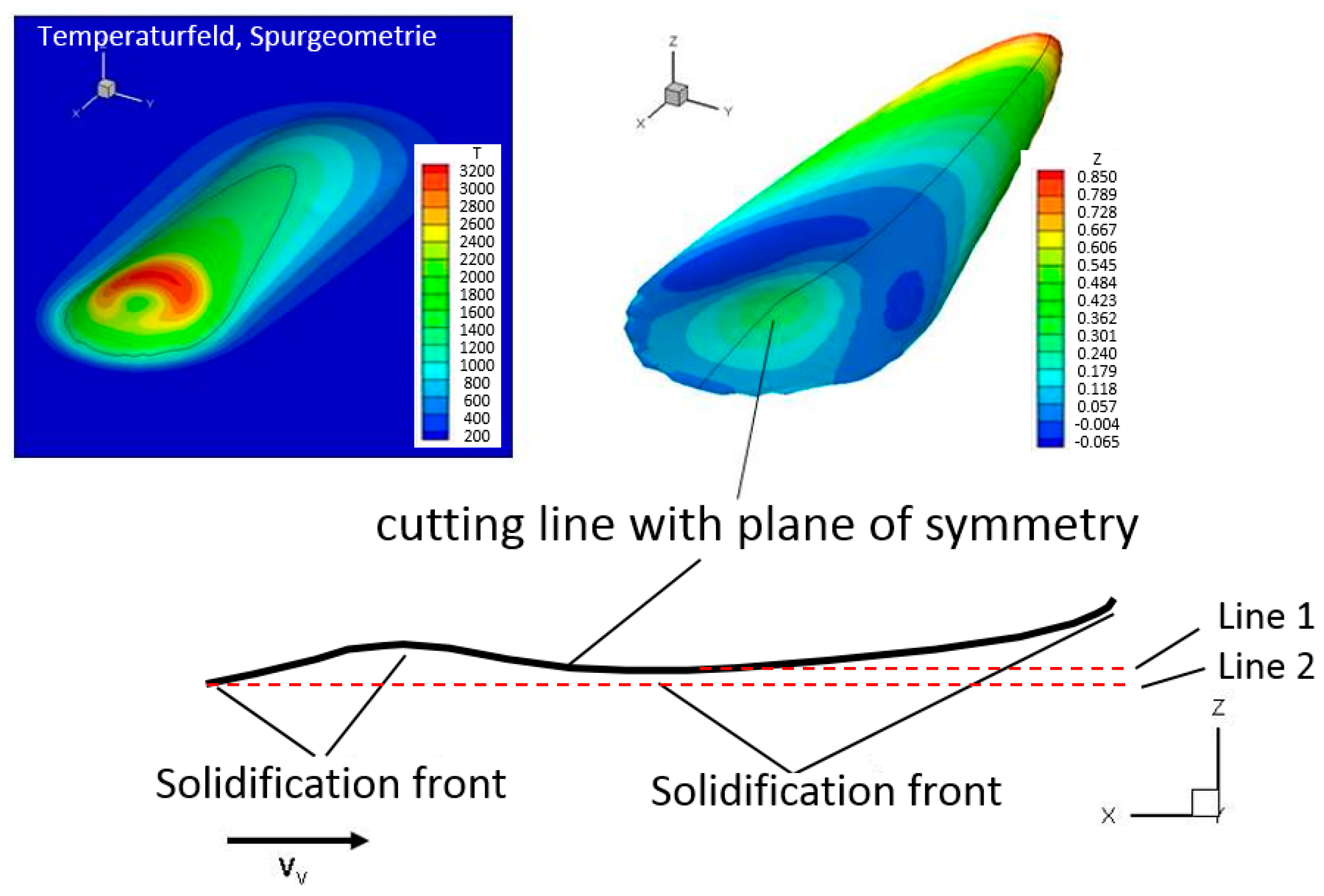
Figure 10.
Transmitted LID (a) and PID (b) for the three-jet nozzle projected onto the track geometry.
Figure 10.
Transmitted LID (a) and PID (b) for the three-jet nozzle projected onto the track geometry.
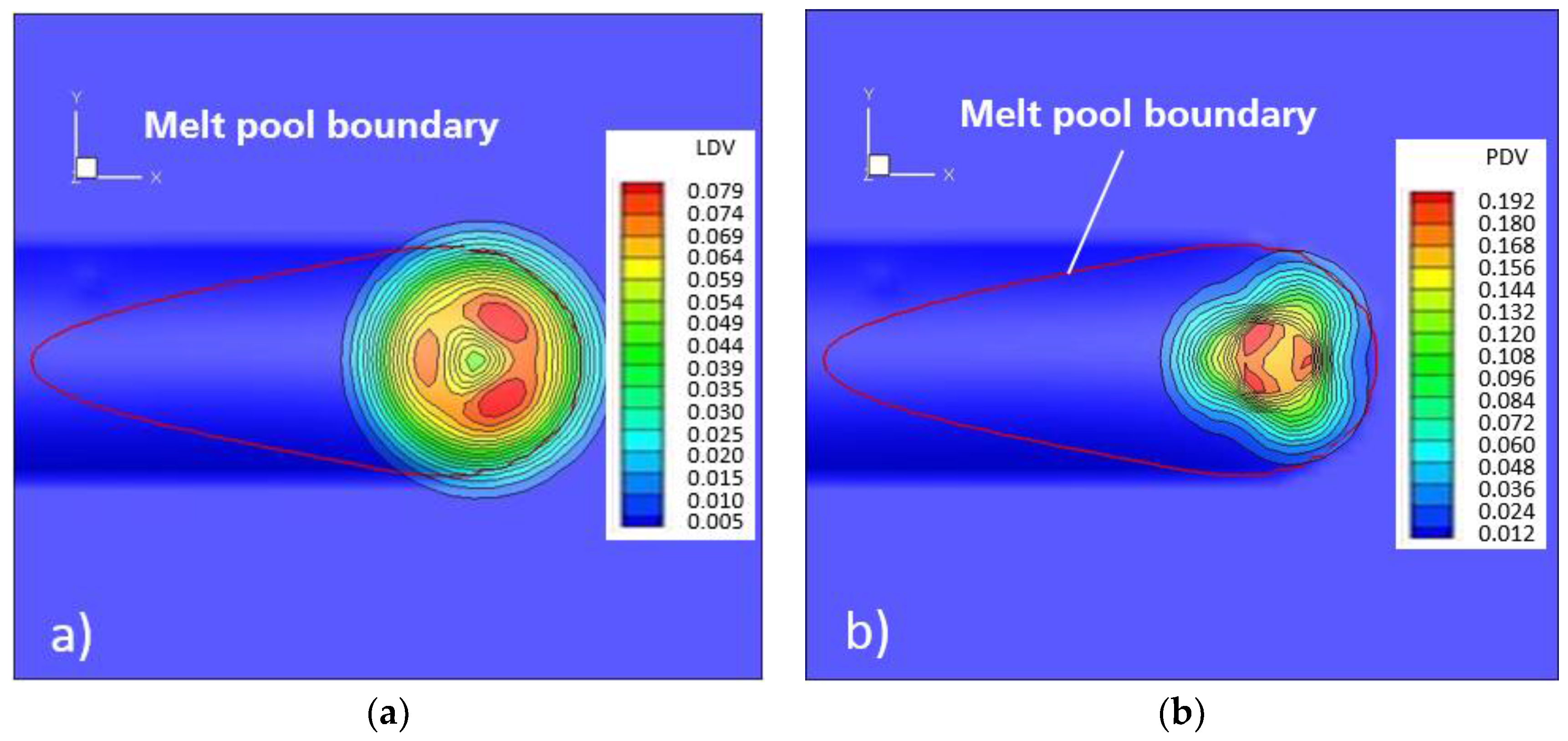
Figure 11.
(a) Temperature distribution and track geometry in a 3D view and (b) track geometry and solid liquid interface in a y-z view in transparency mode for the process with the coaxial nozzle.
Figure 11.
(a) Temperature distribution and track geometry in a 3D view and (b) track geometry and solid liquid interface in a y-z view in transparency mode for the process with the coaxial nozzle.
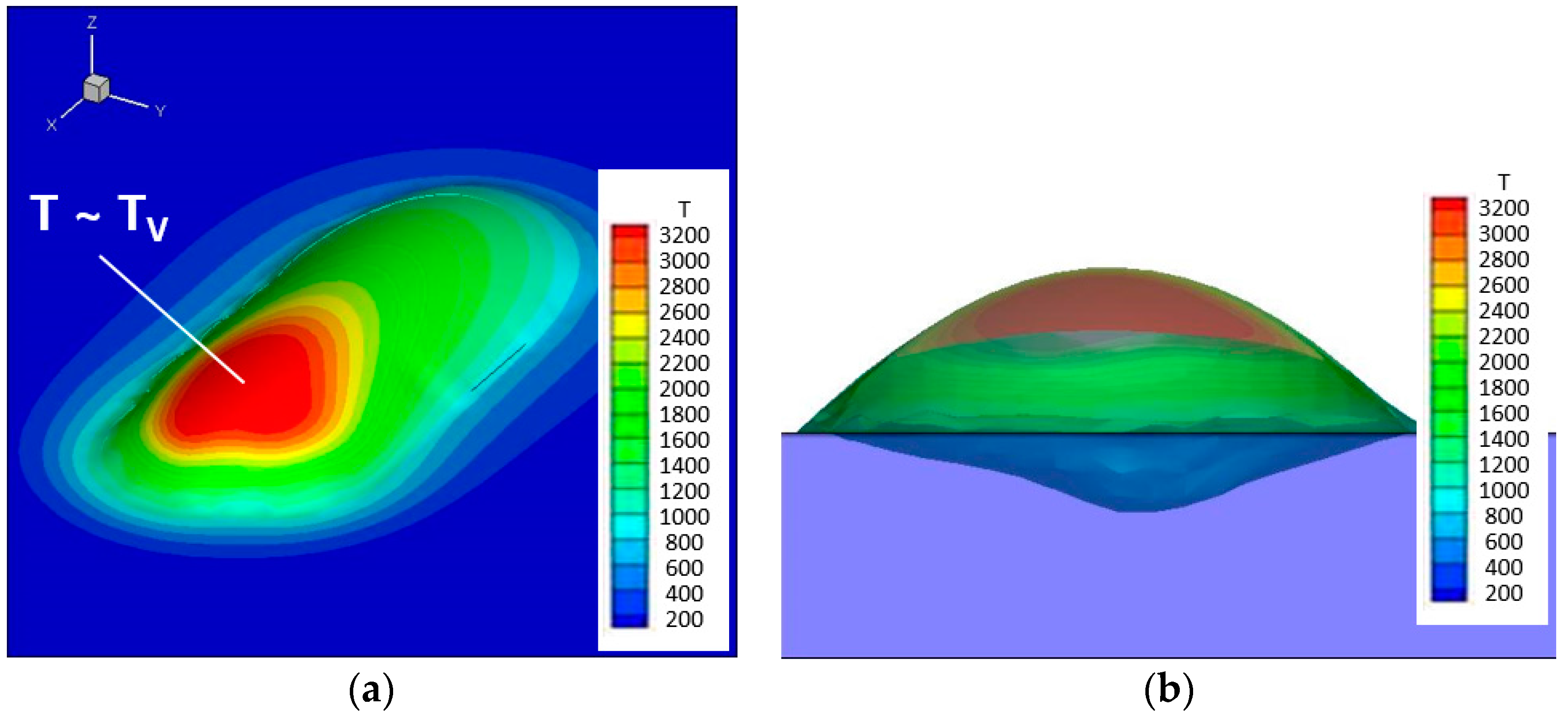
Figure 12.
Metallographic prepared cross-sections of a track processed with the coaxial nozzle at two randomly-selected positions, which are labeled in the Figure as (a,b).
Figure 12.
Metallographic prepared cross-sections of a track processed with the coaxial nozzle at two randomly-selected positions, which are labeled in the Figure as (a,b).
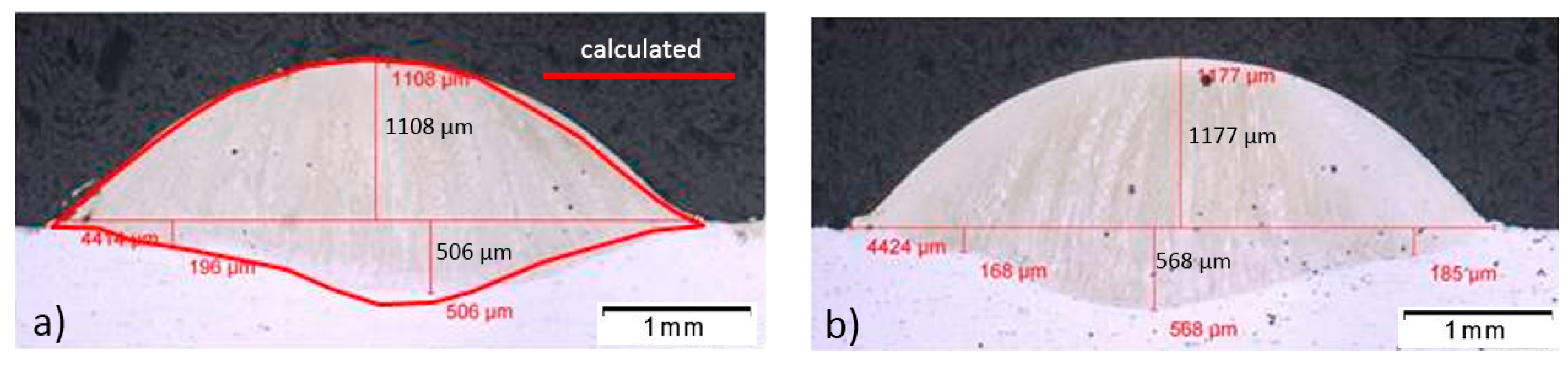
Figure 13.
Transmitted LID (a) and PID (b) for the coaxial nozzle projected onto the track geometry.
Figure 13.
Transmitted LID (a) and PID (b) for the coaxial nozzle projected onto the track geometry.

Table 1.
Tested chemical composition of the used IN718 powder in wt %.
| Element | Ni | Cr | Nb (+Ta) | Mo | Ti | Al |
|---|---|---|---|---|---|---|
| Tested results | 53.51 | 19.08 | 4.89 | 2.98 | 0.99 | 0.68 |
© 2017 by the authors. Licensee MDPI, Basel, Switzerland. This article is an open access article distributed under the terms and conditions of the Creative Commons Attribution (CC BY) license (http://creativecommons.org/licenses/by/4.0/).
Share and Cite
MDPI and ACS Style
Zhong, C.; Pirch, N.; Gasser, A.; Poprawe, R.; Schleifenbaum, J.H. The Influence of the Powder Stream on High-Deposition-Rate Laser Metal Deposition with Inconel 718. Metals 2017, 7, 443. https://doi.org/10.3390/met7100443
AMA Style
Zhong C, Pirch N, Gasser A, Poprawe R, Schleifenbaum JH. The Influence of the Powder Stream on High-Deposition-Rate Laser Metal Deposition with Inconel 718. Metals. 2017; 7(10):443. https://doi.org/10.3390/met7100443
Chicago/Turabian StyleZhong, Chongliang, Norbert Pirch, Andres Gasser, Reinhart Poprawe, and Johannes Henrich Schleifenbaum. 2017. "The Influence of the Powder Stream on High-Deposition-Rate Laser Metal Deposition with Inconel 718" Metals 7, no. 10: 443. https://doi.org/10.3390/met7100443
Note that from the first issue of 2016, this journal uses article numbers instead of page numbers. See further details here.