Development and Application of SKSSIM Simulation Software for the Oxygen Bottom Blown Copper Smelting Process


1
School of Minerals Processing and Bioengineering, Central South University, Changsha 410083, China
2
School of Metallurgy and Environment, Central South University, Changsha 410083, China
3
School of Chemical Engineering, University of Queensland, Brisbane, QLD 4702, Australia
*
Authors to whom correspondence should be addressed.
Metals 2017, 7(10), 431; https://doi.org/10.3390/met7100431
Submission received: 16 September 2017
/
Revised: 2 October 2017
/
Accepted: 3 October 2017
/
Published: 16 October 2017
Abstract
:The oxygen bottom blown copper smelting process (SKS process) is a newly developed intense smelting process, which has been widely applied to copper production in China. A multiphase equilibrium model for the SKS process was established based on its mechanism characteristics and the principle of Gibbs energy minimization, and an efficient simulation software—SKSSIM (SKS Simulation)—was developed based on the model. Industrial data from the SKS process were used to compare with the calculated data from the SKSSIM software. The calculated data on the compositions of slag and matte as well as the distribution ratios of minor elements (such as Pb, Zn, As, Sb and Bi) among the slags, mattes and off-gases were in good agreement with the actual plant data. Accordingly, the SKSSIM simulation software has the potentail to be used for the prediction of smelting production and for optimizing the operating parameters of the SKS process.
1. Introduction
The oxygen bottom blown bath smelting process is a newly developed intensifying smelting process, which has been widely applied to copper [1,2], lead [3,4], and antimony [5] production in China. The first industrial test of the oxygen bottom blown copper smelting process was carried out in the Shuikoushan (SKS) smelter in 1990 and was thus named the SKS process. Later, the process was also called the BBS (bottom blown smelting) or BBF (bottom blown furnace) process. As has been widely discussed in recent years [1,2,6], fundamental studies related to the SKS process are required urgently. Shui et al. [7,8] studied the bath surface wave and mixing phenomena in a SKS furnace. Zhang et al. [9] and Yan et al. [10] studied gas-liquid multi-phase flows in an SKS furnace. Wang et al. [11] studied the mechanism of the oxygen bottom-blown copper smelting process. Néron et al. [12], Rossi et al. [13], Wu [14], Shimpo et al. [15], Tan et al. [16], Chaubal et al. [17] and Nagamori et al. [18] studied multiphase equilibrium thermodynamic modelling approaches for complex chemical reaction systems including the copper metallurgy process. However, no work has been reported on the multiphase equilibrium simulation software based on the mechanism of the SKS process.
In the present study, an efficient thermodynamic simulation software has been developed for the SKS process that is based on its thermodynamic mechanism and the principle of Gibbs energy minimization and is called SKSSIM (SKS Simulation). This work is part of the comprehensive research program to gain a deeper understanding of this new technology.
2. Theoretical Basis of SKSSIM
2.1. Mechanism of the SKS Process
The SKS smelting furnace is a horizontal cylindrical reactor similar to the Noranda or Teniente furnaces, as shown in Figure 1. The oxygen lances are installed at the bottom of the furnace and blow oxygen-enriched air into the molten bath. The oxygen lances are arranged in two rows on the bottom, in the length direction. Oxygen-enriched air is constantly blown into the matte layer from the bottom of the furnace through the lance, is split into tiny flows at high speed and then dispersed in melt mass [11]. When the gas and liquid come into contact a sufficient amoung, this strengthens the efficiency of the reaction in the smelter. Vigorous oxidizing and slagging reactions occur in the furnace.
We developed the mechanism model of the SKS copper smelting process [11], which is the basis of the multiphase equilibrium model of the SKSSIM software. In the mechanism model, the SKS furnace is divided into seven functional layers from top to bottom and three functional regions along the length direction, as shown in Figure 2 and Figure 3. After the copper sulfide concentrates and flux are fed from the top of furnace, the concentrates decompose into Cu2S, FeS, S2, etc. in the mineral decomposition transitioning layer. The Cu2S and FeS sink to form the matte layer and the decomposed S2 goes directly into the gas phase layer. Oxygen-enriched air is blown from the bottom of the furnace into the matte layer by the oxygen lances and almost all oxygen is consumed in the bath. Almost no S2 can make contact and react with the oxygen. As a result, S2 passes directly into the flue and then reacts with secondary supplied oxygen in the flue rather than reacting inside the furnace [11]. Theoretically, the chemical multiphase equilibrium calculations should be based upon the assumption that all the substances are included. However, the S2 from the concentrate—which passes directly into the flue without reaction in the SKS furnace—has been taken into consideration in the multiphase equilibrium model in order to achieve more precise and reliable computational results.
2.2. Thermodynamic Model
The SKS process is a typical multiphase and multicomponent system, coupled with various chemical reactions. According to the second law of thermodynamics, the spontaneous reaction is always conducted towards the direction in which the total Gibbs free energy decreases. An isothermal and isobaric chemical system is at equilibrium when the total Gibbs free energy is at a minimum [12]. It is assumed that the SKS process is under isothermal and isobaric conditions and reaches its thermodynamic equilibrium so that the total Gibbs free energy of the SKS system attains its minimum.
The total Gibbs free energy function [12] for a multiphase and multicomponent system can be expressed as Equation (1):
where Np and Nc are, respectively, the number of phases and number of components in the system. nij is the mole fraction of component i in phase j. μij is the partial molar Gibbs free energy, i.e., the chemical potential of component i in phase j in the system, which is comprised of two parts in order to modify its non-ideality. One part is , the standard Gibbs free energy of the formation of component i in phase j under the system’s temperature and standard pressure. It modifies the impact of temperature on standard Gibbs free energy and can be calculated by Equation (2).
The other part is RTln(), which accounts for the influence of pressure and concentration under non-ideal conditions on the standard Gibbs free energy; R is the ideal gas constant and T is the temperature in Kelvin. fij is the partial fugacity of component i in the phase j, and is the fugacity of component i in the phase j at the reference state. The value of fugacity is dependent on the temperature and pressure of the system. In the SKS process, the gas phase is treated as an ideal gas. The high temperature melts are considered to be the non-ideal liquid solutions. Therefore, an activity coefficient is introduced to substitute fugacity to modify the chemical potential of the constituents in the real solution against the inapplicability of the ideal solution. So the fugacity of the components in the molten phase and the gas phase can be expressed by the Equations (3) and (4) respectively [12,13].
where λij and xij are, respectively, the activity coefficient and mole fraction of component i in the phase j. yij is the partial pressure of component i in the gas phase and P is the total pressure of the gas phase.
At the same time, according to the element conservation law, the inputs of the elements to the system should be equal to the outputs and the mole number of each component should be above zero. So the multiphase equilibrium model is established and the concentrations of the components at equilibrium can be obtained by finding the minimum value of the total Gibbs free energy under a specific operation condition with the elements input and output constraints.
In the SKS process, the elements of Cu, Fe, S, O, N, H, Si, As, Sb, Bi, Pb, Zn, Mg, Ca and Al are taken into consideration in the multiphase equilibrium calculations. When the system is close to equilibrium, three independent stable phases—matte, slag and gas—are formed. The chemical components formed during the attainment of equilibrium are listed in Table 1 [14].
The SKS system is approximated under isothermal and isobaric airtight conditions. The smelting temperature used in the calculation is fixed at 1473 K (1200 °C).
2.3. Thermodynamic Data
2.4. Physical Entrainment
In the period of copper concentrate smelting and further copper matte converting, slag is produced containing copper in the dissolved form as well as the mechanically entrained form. Usually the dissolved copper is much less than the mechanically entrained matte. It is worth mentioning that the mechanically entrained matte is influenced by many factors, such as the operation parameters, the sizes of the matte droplets, the specific gravity and viscosity of the melt, the settling time, etc. Because the multiphase equilibrium model does not involve the mechanically entrained matte, from the model by Nagamori et al. [18], a copper mechanical entrainment model was established to predict the physically entrained copper in the SKS process as follows: Equation (5) for the slag entrainment in the matte phase and Equation (6) for the matte entrainment in the slag phase.
In Equations (5) and (6), Mslag and Mmatte are the calculated mass of slag and matte phase at equilibrium respectively. The and are the calculated apparent slag mass in the matte phase and matte mass in the slag phase respectively. The and are the entrainment coefficient for the slag in matte phase and the matte in slag phase respectively, which are derived based on the actual plant production data [19]. The entrainment coefficients for the slag in the matte phase and the matte in the slag phase are listed in Table 4.
3. Application of SKSSIM
3.1. SKSSIM Software
The particle swarm optimization algorithm, C# computer programming language and Microsoft Visual Studio were used to develop the SKSSIM software (version 1.0, Central South University, Changsha, China), and Figure 4a,b shows the login screen and navigation interface of SKSSIM. SKSSIM is an efficient simulation software for the SKS process, which is based on the SKS smelting mechanism and theory of Gibbs free energy minimization. SKSSIM has been successfully used in the actual production in Dongying Fangyuan Nonferrous Metals Co. Ltd. (Dongying, China) and Minmetals copper (Hunan) Co. Ltd. (Hengyang, China). The main function of the SKSSIM software is to simulate and optimize the SKS process. The interfaces of SKSSIM in the steady and variable working conditions are present in Figure 5 and Figure 6 respectively. The calculation results can be saved in the Microsoft Excel spreadsheet format.
3.2. Application of SKSSIM Software
The initial conditions and operation parameters, which are crucial for the software calculations, were taken from Dongying Fangyuan Nonferrous Metals Co. Ltd. The compositions of the mixed concentrates charged into the furnace are listed in Table 5, and the operation parameters are listed in the Table 6.
3.3. Calculated Results
Dongying Fangyuan Nonferrous Metals Co. Ltd. is producing a high grade matte with above 70% Cu and the smelting process achieves the autogenous smelting. The calculation is based on its initial conditions and operation parameters. The industrial data under the stable operation conditions are compared with the calculated data as shown in Table 7 and Table 8.
Table 7 shows that the calculated matte and slag compositions are in good agreement with the industrial values. The calculated and industrial matte grades are 70.31% and 70.77% respectively. The calculated and industrial Fe in matte are 4.80% and 5.52% respectively.
The calculated and actual plant data on the minor element distributions among matte, slag and gas phases are shwon in Table 8 and agree well. The calculated minor elements in matte, slag and gas phases are arsenic 6.23%, 11.06%, 82.71%, antimony 12.58%, 72.30%, 15.12%, bismuth 18.74%, 11.13%, 70.13%, lead 56.71%, 23.47%, 19.82% and zinc 17.35%, 66.46%, 16.19%, respectively. The calculated results clearly show the varying trends of minor elements in the matte, slag and gas phases.
The above comparisons demonstrate that the SKSSIM software can well reproduce the industrial data. Consequently, the reliability of SKSSIM software is validated. The SKSSIM software contains important practical values, and can be further used to predict the element distributions, as well as optimize the operating parameters for the SKS process.
4. Conclusions
An efficient simulation software for the SKS process, named SKSSIM, was developed based on the thermodyanamic mechanism of SKS process and the theory of Gibbs energy minimization. Good agreements were obtained between the calculated results by SKSSIM and the actual plant data, which validates the reliability of the SKSSIM software for the SKS process. The software can be used to predict the tendencies of compositions of smelting products and the distribution ratios of minor elements (such as Pb, Zn, As, Sb and Bi) among slag, matte and gas phases in the SKS furnace. The software deepens the understanding of the SKS process and is of great significance for further optimizing operation parameters and regulating the production if the SKS process is dealing with complex copper concentrates.
Acknowledgments
The authors would like to acknowledge the National Nature Science Foundation of China (No. 51620105013) for financial support, and Dongying Fangyuan Nonferrous Metals Co., Ltd. for providing the industrial production data.
Author Contributions
Xueyi Guo, Tao Jiang and Baojun Zhao designed the research. Qinmeng Wang carried out the research and wrote the paper. Xueyi Guo, Qinghua Tian, Mao Chen, and Baojun Zhao reviewed and contributed to the final manuscript.
Conflicts of Interest
The authors declare no conflict of interest.
References
- Coursol, P.; Mackey, P.J.; Kapusta, J.P.T.; Valencia, N.C. Energy consumption in copper smelting: A new Asian horse in the race. JOM 2015, 67, 1066–1074. [Google Scholar] [CrossRef]
- Wang, Q.M.; Guo, X.Y.; Tian, Q.H.; Chen, M.; Zhao, B.J. Reaction mechanism and distribution behavior of arsenic in the bottom blown copper smelting process. Metals 2017, 7, 302. [Google Scholar] [CrossRef]
- Li, W.F.; Zhan, J.; Fan, Y.Q.; Wei, C.; Zhang, C.F.; Hwang, J.Y. Research and industrial application of a process for direct reduction of molten high-lead smelting slag. JOM 2017, 69, 784–789. [Google Scholar] [CrossRef]
- Chen, L.; Hao, Z.D.; Yang, T.Z.; Liu, W.F.; Zhang, D.C.; Zhang, L.; Bin, S.; Bin, W.D. A comparison study of the oxygen-rich side blow furnace and the oxygen-rich bottom blow furnace for liquid high lead slag reduction. JOM 2015, 67, 1123–1129. [Google Scholar] [CrossRef]
- Liu, W.F.; Yang, T.Z.; Zhang, D.C.; Chen, L.; Liu, Y.F. A new pyrometallurgical process for producing antimony white from by-product of lead smelting. JOM 2014, 66, 1694–1700. [Google Scholar] [CrossRef]
- Qu, S.L.; Dong, Z.Q.; Chen, T. Distribution of minor elements in complex copper concentrates in oxygen-enriched bottom blown smelting process. China Nonferrous Metall. 2016, 3, 22–24. [Google Scholar]
- Shui, L.; Cui, Z.X.; Ma, X.D.; Rhamdhani, M.A.; Nguyen, A.V.; Zhao, B.J. Mixing phenomena in a bottom blown copper smelter: A water model study. Metall. Mater. Trans. B 2015, 46, 1218–1225. [Google Scholar] [CrossRef]
- Shui, L.; Cui, Z.X.; Ma, X.D.; Rhamdhani, M.A.; Nguyen, A.V.; Zhao, B.J. Understanding of bath surface wave in bottom blown copper smelting furnace. Metall. Mater. Trans. B 2016, 47, 135–144. [Google Scholar] [CrossRef]
- Zhang, Z.Y.; Chen, Z.; Yan, H.J.; Liu, F.K.; Liu, L.; Cui, Z.X.; Shen, D.B. Numerical simulation of gas-liquid multi-phase flows in oxygen enriched bottom-blown furnace. Chin. J. Nonferrous Met. 2012, 22, 1826–1834. (In Chinese) [Google Scholar]
- Yan, H.J.; Liu, F.K.; Zhang, Z.Y.; Gao, Q.; Liu, L.; Cui, Z.X.; Shen, D.B. Influence of lance arrangement on bottom-blowing bath smelting process. Chin. J. Nonferrous Met. 2012, 22, 2393–2400. (In Chinese) [Google Scholar]
- Wang, Q.M.; Guo, X.Y.; Tian, Q.H. Copper smelting mechanism in oxygen bottom-blown furnace. Trans. Nonferrous Met. Soc. China 2017, 27, 946–953. [Google Scholar] [CrossRef]
- Néron, A.; Lantagne, G.; Marcos, B. Computation of complex and constrained equilibria by minimization of the Gibbs free energy. Chem. Eng. Sci. 2012, 82, 260–271. [Google Scholar] [CrossRef]
- Rossi, C.; Filho, L.C.; Guirardello, R. Gibbs free energy minimization for the calculation of chemical and phase equilibrium using linear programming. Fluid. Phase. Equilibr. 2009, 278, 117–128. [Google Scholar] [CrossRef]
- Wu, W. Mathematical Model Research and System Development of Multiphase Equilibrium in Copper Flash Smelting. Master’s Thesis, Jiangxi University of Science and Technology, Ganzhou, China, June 2007. [Google Scholar]
- Shimpo, R.; Goto, S.; Ogawa, O. An improved computer program for equilibrium calculations. Metall. Trans. A 1993, 24, 1882–1889. [Google Scholar] [CrossRef]
- Tan, P.; Zhang, C. Computer model of copper smelting process and distribution behaviors of accessory elements. J. Cent. South Univ. Technol. 1997, 4, 36–41. [Google Scholar] [CrossRef]
- Chaubal, P.C.; Sohn, H.Y.; George, D.B.; Bailey, L.K. Mathematical modeling of minor-element behavior in flash smelting of copper concentrates and flash converting of copper mattes. Metall. Trans. B 1989, 20, 39–51. [Google Scholar] [CrossRef]
- Nagamori, M.; Mackey, P.J. Thermodynamics of copper matte converting: Part I. Fundamentals of the noranda process. Metall. Trans. B 1978, 9, 255–265. [Google Scholar] [CrossRef]
- Liao, L. Development and Application of Simulation Platform in the Oxygen Bottom Blowing Copper Smelting Process. Master’s Thesis, Central South University, Changsha, China, June 2016. [Google Scholar]
Figure 1.
Schematic diagram of an SKS (Shuikoushan) smelting furnace.

Figure 2.
SKS mechanism model-I.
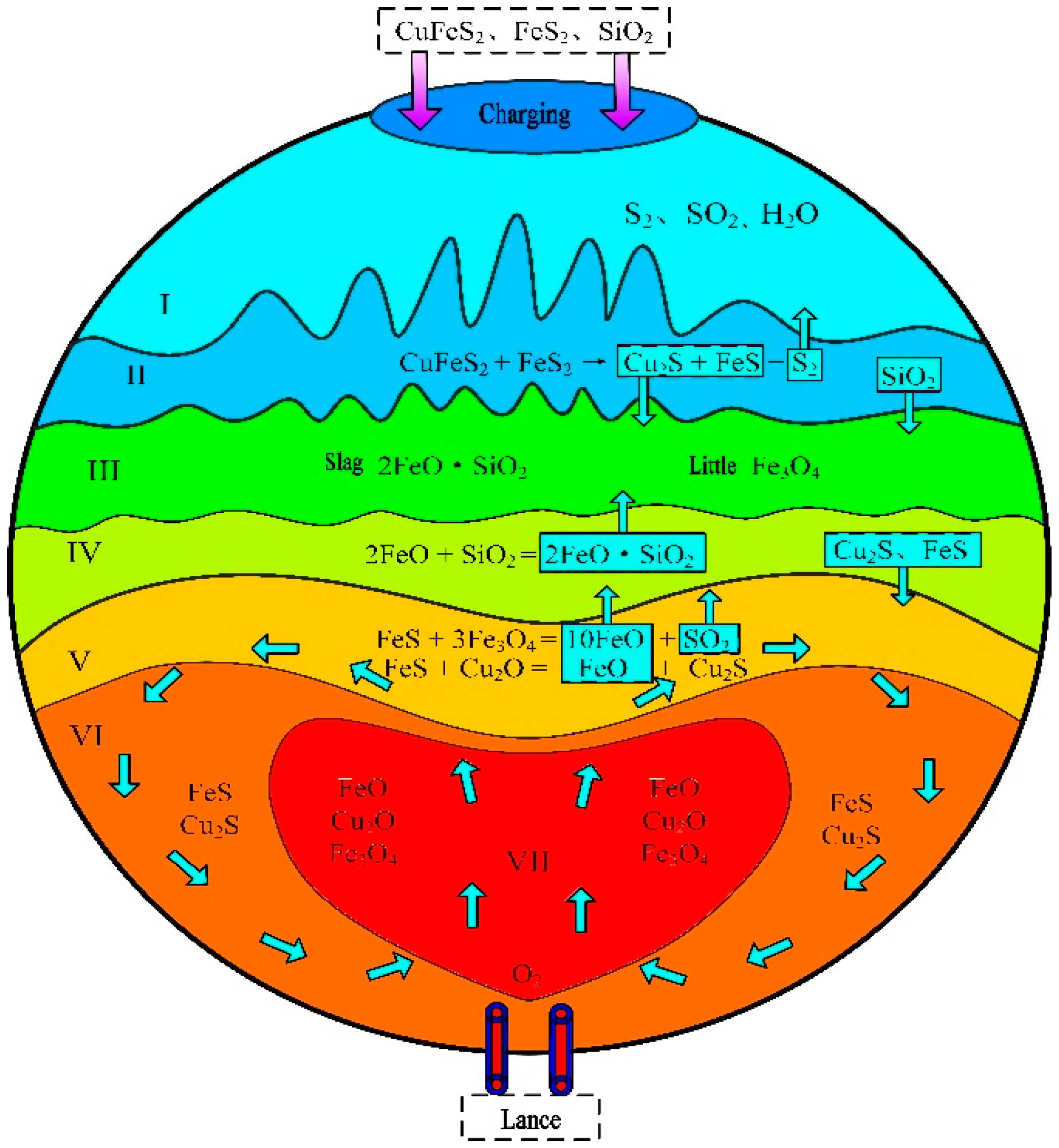
Figure 3.
SKS mechanism model-II.
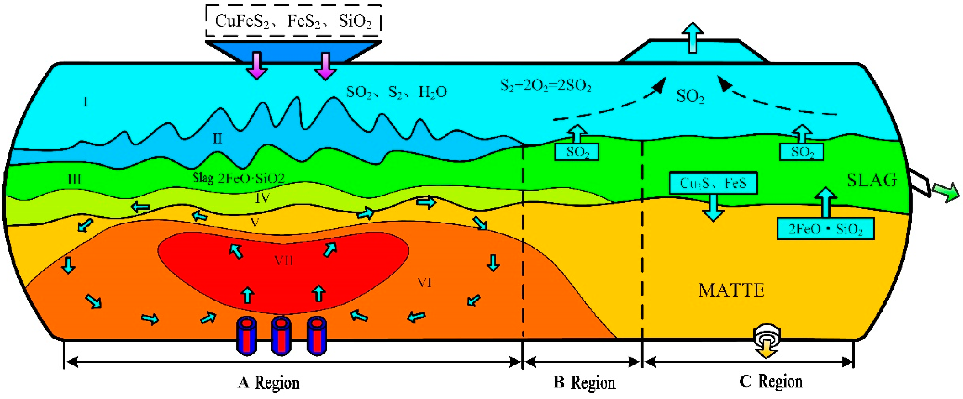
Figure 4.
Login screen and navigation interface of SKSSIM: (a) login screen; (b) navigation interface.
Figure 4.
Login screen and navigation interface of SKSSIM: (a) login screen; (b) navigation interface.
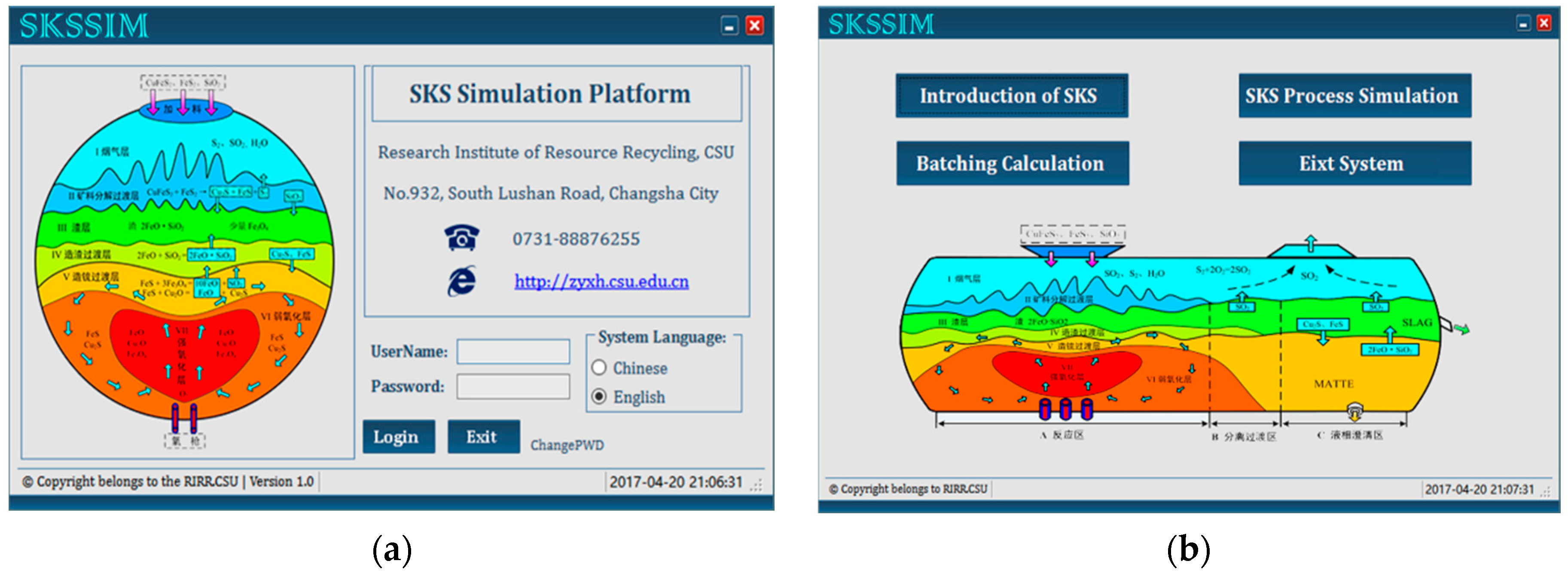
Figure 5.
Input interfaces in the steady working condition: (a) calculation condition; (b) algorithm parameters.
Figure 5.
Input interfaces in the steady working condition: (a) calculation condition; (b) algorithm parameters.
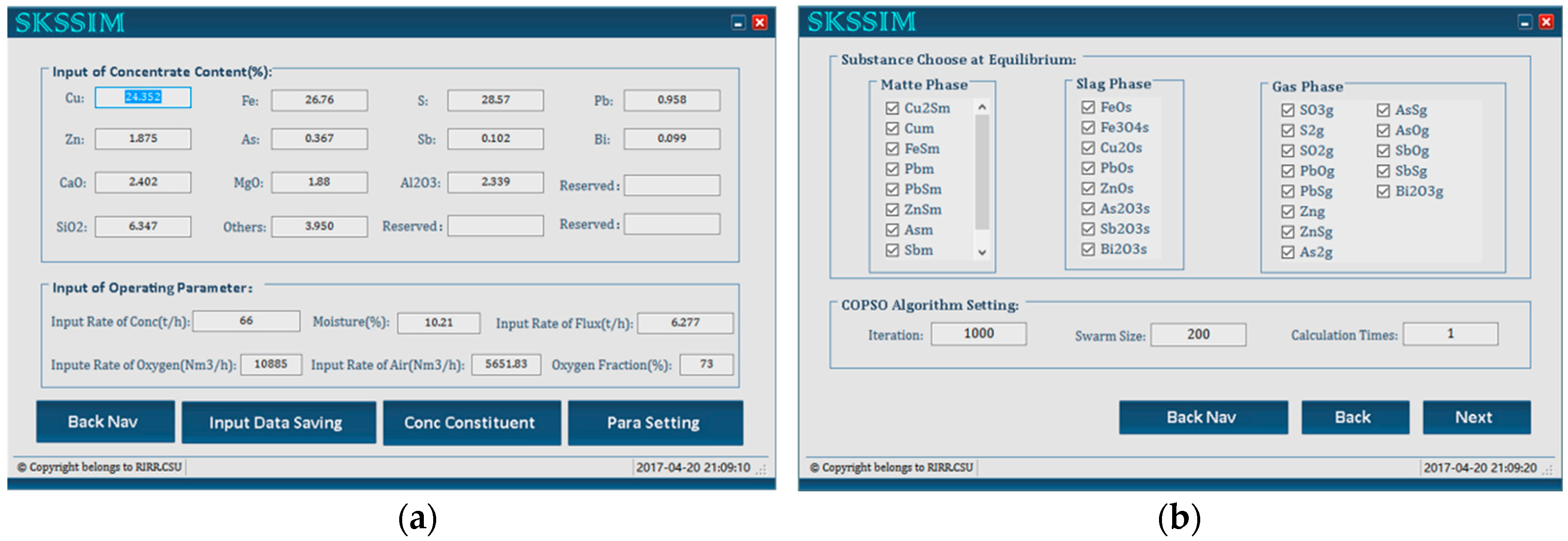
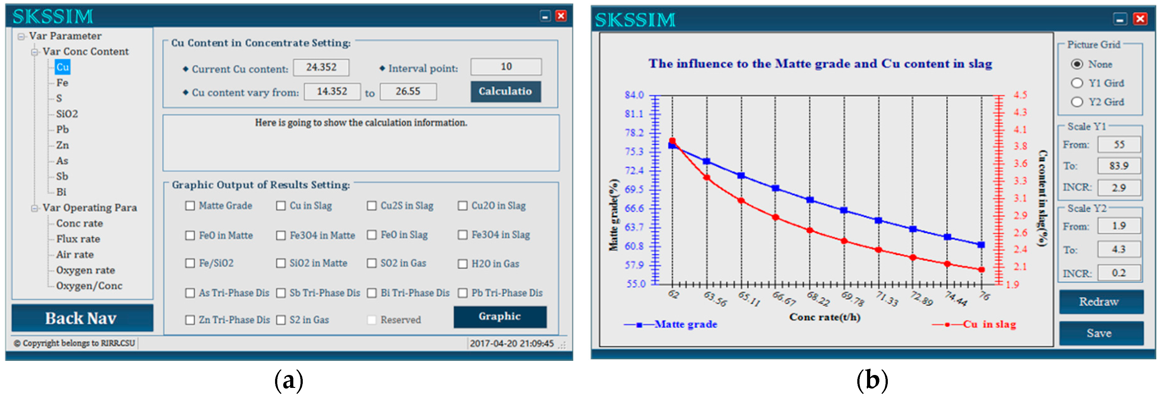
Figure 6.
Interfaces in the variable working condition: (a) input interface; (b) output interface.


Table 1.
Chemical components in SKS copper smelting process.
| Phases | Chemical Components |
|---|---|
| Gas | SO2, SO3, S2, O2, N2, H2O, PbO, PbS, Zn, ZnS, As2, AsO, AsS, SbO, SbS, BiS |
| Slag | FeO, Cu2S, Cu2O, Fe3O4, FeS, PbO, ZnO, As2O3, Sb2O3, Bi2O3, SiO2, CaO, MgO, Al2O3 |
| Matte | Cu2S, Cu, FeS, FeO, Fe3O4, Pb, PbS, ZnS, As, Sb, Bi |
Table 2.
Phase entrainment coefficient in the SKS process.
| Components | Phase | Activity Coefficient |
|---|---|---|
| Cu2S | Matte | 1 |
| FeS | Matte | |
| Cu | Matte | 14 |
| FeO | Matte | |
| Fe3O4 | Matte | |
| Pb | Matte | 23 |
| PbS | Matte | |
| ZnS | Matte | |
| As | Matte | |
| Sb | Matte | |
| Bi | Matte | |
| FeO | Slag | |
| SiO2 | Slag | 2.1 |
| Fe3O4 | Slag | |
| Cu2O | Slag | |
| FeS | Slag | 70 |
| Cu2S | Slag | |
| PbO | Slag | |
| ZnO | Slag | |
| As2O3 | Slag | |
| Sb2O3 | Slag | |
| Bi2O3 | Slag |
Table 3.
Standard Gibbs free energy (J·mol−1) of formation of each component.
| Components | State | ||
|---|---|---|---|
| Cu2S | liquid | −145,349 | 43.06 |
| FeS | liquid | −135,556 | 43.06 |
| PbS | liquid | −151,881 | 79.67 |
| ZnS | solid | −391,434 | 203.08 |
| Cu2O | liquid | −137,139 | 54.25 |
| FeO | liquid | −259,244 | 62.38 |
| Fe3O4 | solid | −1,097,693.74 | 305.93 |
| As2O3 | liquid | −1,215,325.18 | 457.37 |
| Sb2O3 | liquid | −687,438 | 237.86 |
| Bi2O3 | liquid | −563,470 | 257.66 |
| PbO | liquid | −196,818 | 79.15 |
| ZnO | solid | −475,260 | 208.63 |
| SiO2 | liquid | −912,677 | 180.92 |
| SO3 | gas | −459,543 | 165.15 |
| SO2 | gas | −361,500 | 72.49 |
| As2 | gas | −415,418 | 113.24 |
| AsS | gas | −184,465 | 45.88 |
| AsO | gas | −257,759 | 46.12 |
| SbO | gas | −126,601 | −60.35 |
| SbS | gas | 103,194 | −59.91 |
| BiS | gas | −0.057 | 96.74 |
| PbO | gas | 60,860 | −54.39 |
| PbS | gas | 57,812 | −53.83 |
| ZnS | gas | 13,200 | 32.15 |
Table 4.
Phase entrainment coefficient in the SKS process.
| Matte Grade | Phase Entrainment Coefficient | |
|---|---|---|
| (%) | (%) | |
| 50 | 2.2 | 2.8 |
| 65 | 2.9 | 3.2 |
| 75 | 3.2 | 3.8 |
Table 5.
Compositions of the mixed concentrates into the furnace.
| Compositions | Cu | Fe | S | Pb | Zn | As | Sb | Bi | SiO2 | MgO | CaO | Al2O3 | Others |
|---|---|---|---|---|---|---|---|---|---|---|---|---|---|
| Content (wt %) | 24.4 | 26.8 | 28.6 | 0.96 | 1.9 | 0.37 | 0.10 | 0.10 | 6.4 | 1.9 | 2.4 | 2.3 | 3.9 |
Table 6.
Industrial operation parameters in SKS process.
| Operation Parameters | SKS Plant Data |
|---|---|
| Charging rate of dry mixed concentrates (t/h) | 66 |
| Water percent in the mixed concentrates (%) | 10.21 |
| Charging rate of flux (t/h) | 5.277 |
| Smelting temperature (K) | 1473 |
| Negative pressure in furnace (Pa) | 50–200 |
| Flowrate of pure oxygen (Nm3/h) | 10,885 |
| Flowrate of air (Nm3/h) | 5651 |
| Volume of O2 in oxygen-enriched air (%) | 73 |
| Matte grade (%) | 70 |
| Oxygen efficiency (%) | 99 |
Table 7.
Comparison of predicted data with actual plant data of matte and slag compositions in SKS process.
Table 7.
Comparison of predicted data with actual plant data of matte and slag compositions in SKS process.
| Compositions (wt %) | Cu | Fe | S | Pb | Zn | As | Sb | Bi | SiO2 | |
|---|---|---|---|---|---|---|---|---|---|---|
| Plant Data | matte | 70.77 | 5.52 | 20.22 | 1.73 | 1.07 | 0.07 | 0.04 | 0.06 | 0.51 |
| slag | 3.16 | 42.58 | 0.86 | 0.43 | 2.19 | 0.08 | 0.13 | 0.02 | 25.24 | |
| This Work | matte | 70.31 | 4.80 | 20.38 | 1.69 | 1.02 | 0.07 | 0.04 | 0.06 | 0.82 |
| slag | 2.93 | 42.07 | 0.73 | 0.37 | 2.08 | 0.07 | 0.12 | 0.02 | 25.18 | |
Table 8.
Comparison of predictions with actual plant data of the minor elements distributions in SKS process.
Table 8.
Comparison of predictions with actual plant data of the minor elements distributions in SKS process.
| Phases | Plant Data (%) | This Work (%) | ||||||||
|---|---|---|---|---|---|---|---|---|---|---|
| As | Sb | Bi | Pb | Zn | As | Sb | Bi | Pb | Zn | |
| Matte | 5.91 | 12.31 | 19.10 | 55.61 | 17.76 | 6.23 | 12.58 | 18.74 | 56.71 | 17.35 |
| Slag | 12.08 | 71.05 | 11.40 | 24.91 | 64.86 | 11.06 | 72.30 | 11.13 | 23.47 | 66.46 |
| Gas | 82.01 | 16.64 | 69.50 | 19.48 | 17.38 | 82.71 | 15.12 | 70.13 | 23.47 | 16.19 |
© 2017 by the authors. Licensee MDPI, Basel, Switzerland. This article is an open access article distributed under the terms and conditions of the Creative Commons Attribution (CC BY) license (http://creativecommons.org/licenses/by/4.0/).
Share and Cite
MDPI and ACS Style
Wang, Q.; Guo, X.; Tian, Q.; Jiang, T.; Chen, M.; Zhao, B. Development and Application of SKSSIM Simulation Software for the Oxygen Bottom Blown Copper Smelting Process. Metals 2017, 7, 431. https://doi.org/10.3390/met7100431
AMA Style
Wang Q, Guo X, Tian Q, Jiang T, Chen M, Zhao B. Development and Application of SKSSIM Simulation Software for the Oxygen Bottom Blown Copper Smelting Process. Metals. 2017; 7(10):431. https://doi.org/10.3390/met7100431
Chicago/Turabian StyleWang, Qinmeng, Xueyi Guo, Qinghua Tian, Tao Jiang, Mao Chen, and Baojun Zhao. 2017. "Development and Application of SKSSIM Simulation Software for the Oxygen Bottom Blown Copper Smelting Process" Metals 7, no. 10: 431. https://doi.org/10.3390/met7100431
Note that from the first issue of 2016, this journal uses article numbers instead of page numbers. See further details here.