Development of Metallographic Etchants for the Microstructure Evolution of A6082-T6 BFSW Welds


1
Department of Mechanical Engineering, University of Canterbury, Christchurch 8140, New Zealand
2
Advanced Manufacturing Centre, Faculty of Manufacturing Engineering, Universiti Teknikal Malaysia Melaka, Durian Tunggal 76100, Melaka, Malaysia
*
Author to whom correspondence should be addressed.
Metals 2017, 7(10), 423; https://doi.org/10.3390/met7100423
Submission received: 4 September 2017
/
Revised: 3 October 2017
/
Accepted: 6 October 2017
/
Published: 11 October 2017
/
Corrected: 16 February 2024
(This article belongs to the Special Issue Recent Achievements in Rotary, Linear and Friction Stir Welding of Metals Alloys)
Abstract
:BACKGROUND—The solid-phase joining of A6082-T6 plates by bobbin friction stir welding (BFSW) is problematic. Better methods are needed to evaluate the microstructural evolution of the weld. However, conventional Al reagents (e.g., Keller’s and Kroll’s) do not elucidate the microstructure satisfactorily, specifically regarding grain size and morphology within the weld region. APPROACH—We developed innovative etchants for metallographic observations for optical microscopy. RESULTS—The macrostructure and microstructure of A6082-T6 BFSW welds were clearly demonstrated by optical microscopy analysis. The microetching results demonstrated different microstructures of the Stir Zone (S.Z) distinct from the Base Metal (B.M) and Heat Affected Zone (HAZ) & Thermo-mechanical Affected Zone (TMAZ). The micrographs showed a significant decrease in grain size from 100 μm in B.M to ultrafine 4–10 μm grains for the S.Z. Also, the grain morphology changed from directional columnar in the B.M to equiaxed in the S.Z. Furthermore, thermomechanical recrystallization was observed by the morphological flow of the grain distortion in HAZ and TMAZ. The etchants also clearly show the polycrystalline structure, microflow patterns, and the incoherent interface around inclusion defects. ORIGINALITY—Chemical compositions are identified for a suite of etchant reagents for metallographic examination of the friction-stir welded A6082-T6 alloy. The reagents have made it possible to reveal microstructures not previously evident with optical microscopy.
1. Introduction
1.1. Context
Friction stir welding (FSW) was introduced by the welding institute (TWI) [1,2] as a solid-state joining process whereby a rapidly rotating tool is physically moved along the interface of two plates [3,4]. As the weld-line bond is formed, the material from the advancing side (A.S) and retreating side (R.S) mix together to form the bonding layer [5], in a solid phase mixing process. A material that would be attractive to weld with the FSW method is aluminium A6082-T6. This is a useful marine grade aluminium alloy with excellent mechanical properties, good thermal weldability, good machinability, and excellent corrosion resistance [6]. It is suitable for structural applications including bridges, shipbuilding, and marine superstructures [7,8,9]. However, the material suffers from poor weldability using FSW [10]. One of the obstacles to better understanding the poor weldability is the difficulty of visualizing the microstructure of the weld region [10,11,12,13]. This is problematic as the material responds poorly to known etchants, hence it is difficult to visualize the grain boundaries and the internal flow features [7,8,10].
This work presents a new set of etchants and related processes for etching A6082-T6. We show that these are able to show multiple features of the microstructure.
1.2. Background to Friction Stir Welding
To increase the productivity of FSW and decreasing of structural defects, various modifications have been progressed on Conventional-FSW (CFSW) [3,14]. Bobbin friction stir welding (BFSW) is a variant where a symmetrical tool (consisting of two shoulders, one on each side of the workpiece connected by the tool pin) creates a fully penetrated butt joint by stirring and mixing of the plasticised material [9,15,16]. The schematic of the BFSW process for the butt-joint position is shown in Figure 1a. The process has demonstrated capabilities in industrial applications such as fabrication of spacecraft fuel tanks [1], pressure vessels [5], shipbuilding [9], and marine superstructures [17,18].
1.3. Characteristics of Aluminium 6082-T6 in BFSW
A6082-T6 is a metallurgically stabilized Al-Si-Mg alloy which is grain-refined by addition of manganese (Mn) [19]. The standard element composition is presented in Table 1. An aging or tempering heat treatment is used to stabilize the microstructure and increase the mechanical properties [17].
The most common temper for A6082 is the T6 heat treatment process, which is a precipitation hardening procedure including three time/temperature cycles; solutionising, quenching, and artificial aging [11,21]. For details of the T6 heat treatment for A6082 see [22,23]. Solid solution strengthening involves formation of a single-phase supersaturated solid solution via quenching [24]. Unlike ordinary tempering, alloys must be kept at elevated temperature for some hours to achieve uniform precipitation [8], hence “ageing”. Since A6082 is a heat treatable alloy, strength is reduced in the weld region [25].
1.4. Visualising the Cross Section of BFSW Welds
1.4.1. Zones within the Weld
The transverse section of a BFSW weld-line reveals three typical zones. The stir zone (S.Z) is the centre region of the weld and is distinguished by an hourglass pattern at the A.S and the R.S borders of the cross section [1,26,27,28]. In this region, the thermomechanically distorted grains are plasticized and then recrystallized by the stirring action of the tool [27]. The adjacent region is the thermo-mechanical affected zone (TMAZ), created by the thermal and mechanical effects of the friction and stirring [28]. Similar to other welding processes, the heat affected zone (HAZ), an area of the base metal (B.M) which has an altered microstructure by heat flux effects during the process, is located between the TMAZ and B.M [29]. The welding process may introduce defects at macro- or microscopic level, and these affect weld quality. Microstructure observation of the weld texture typically shows a transition in morphology and grain size distribution [11,30].
1.4.2. Metallography
Metallographic measurement is an effective technique to characterize the microstructural details of the various metals or alloys in cross section [24,31]. In comparison with electron microscopy, the etching method is fast and inexpensive. In principle, it is able to show grain size, morphology, and distribution [32]. There are different macro-etchant or micro-etchant solutions which can be used by immersion, swabbing, or electrolytic processes [33,34]. Other techniques like electron backscatter diffraction (EBSD) can be used for microstructural-crystallographic characterization to study any crystalline or polycrystalline material, but preparation of the aluminium sample for EBSD is time consuming and the equipment is considerably more expensive than optical microscopes [35].
1.5. Issues with the Metallography of Aluminium Alloys
In the case of aluminium alloys, the most common etchants are Keller’s etchant (95 mL H2O, 2.5 mL HNO3, 1.5 mL HCl, 1.0 mL HF) and Kroll's reagent (92 mL H2O, 6.0 mL HNO3, 2.0 mL HF) [32,36]. Also, anodizing using Barker’s reagent (5 mL HBF4, 200 mL H2O) and colour etching by Weck’s reagent (4 g KMnO4, 1 g of NaOH, 100 mL H2O) are widely applied to reveal the microstructure and grain boundaries (G.B) [37].
A significant obstacle to metallographic measurement of weld characterisation of BFSW A6082-T6 is the low efficacy of existing reagents. Keller’s reagent has been unsuccessful for observing the microstructure [10,13]. Also, Kroll’s reagent only showed some narrow lines at the borders of the weld region [15]. More specifically, thermomechanical evaluation requires that the fine structure of A6082-T6 alloy be delineated in grain-refined regions; and this necessitates that other etchants be used to improve the microstructural observations.
The problem has two causes [38,39]. First, the tempered structure of A6082-T6 base metal has a uniform and stabilized solid solution [38]. The T6 condition retains the hardening particles in the solid solution as opposed to precipitating them on the grain boundaries where they would increase the contrast. This makes it hard to distinguish the grain boundaries from the grains. Second, the solid phase plastic deformation of the welding process fragments the grains to ultrafine size (in the range of 10 μm or below). This further reduces the ability to detect grain boundaries [39].
2. Materials and Methods
2.1. Purpose
There is a need to develop better etching methods for A6082-T6. Specifically, the etching process needs to distinguish grain boundaries down to the ultrafine size, show the morphological flow originated from the grain fragmentation during the stirring process (which is important for processes involving internal flow), preferably reveal some thermomechanical features at higher magnification (for studying recrystallization), and ideally not require electro-polishing or anodising. The objective was to develop such an etching solution and process.
2.2. Approach
We started with the idea that it is necessary to improve the contrast at grain boundaries, and that this might be achieved by a chemical attack followed by a doping process. The details of the doping mechanism need to be described by transition state theory and the activated complex, which are beyond the scope of this paper, but as a brief explanation: using some multi-stage reactions, the unstable reagents can create an activation of the surface using the metal ions and consequently the ion migration into the grain boundaries can improve the contrasting patterns there.
To make the etchant solution, a trial and error procedure was applied. Different compositions of the chemical solutions were developed specifically, and results compared regarding the resolution of the grain size and morphology. HNO3 is common between the majority of Al reagents [36,37,40]. Also, HF is one of the strongest acids for chemical attack on silicon-containing compounds [37,40]. Dissolution of the Al2O3 film on the Al surface can be progressed by H3PO4 [37]. Furthermore, using an alkaline developer (NaOH) can improve the grain boundary contrast [36,37].
The etching process may be accelerated by higher temperature or immersion in a solution under ultrasonic fields. Depending on chemical composition of the etchants, compounds of solutions can be applied in one-step or multi-step processes. This set of arrangements gives the boundaries a rougher and darker appearance than inside the grain when viewed under the optical microscope.
After completion of the etching process, the macrostructure and microstructure of the weld can be studied by using a stereomicroscope and light-optical microscopy analysis, respectively. In this part, besides demonstrating the recrystallized microstructure of the weld region in the S.Z, we focus on a thermomechanical comparison of grain size, morphology, and flow distribution in B.M, HAZ and TMAZ and S.Z different regions of the weld. Also, by showing the results related to the recrystallization and a morphological flow gradient for the grain distortion from the B.M towards the S.Z, the thermo-mechanical behaviour of the BFSW process can be explained.
2.3. Experimental Welding Process
In this study, the BFSW process was done on 6 mm thick A6082-T6 Al alloy plates for the base metal. The plates were cut into two pieces of 250 (length) mm × 75 mm (width) and set for a butt joint.
Figure 1b demonstrates the geometric details of the fixed bobbin tool utilized for this research. The geometry and process parameters were based on welding trials in the literature [41]. The threaded pin was modified by adding three symmetrical flat surfaces (tri-flat) to provide a more homogenized stirring condition. Also, a 360 degree inward-flowing spiral pattern was inscribed on both shoulders surfaces, i.e., a scroll feature. Diameter (D) ratio (DShoulder/DPin) was 3, and the compression ratio (difference between the biting gap of the bobbin tool and thickness of the workpiece plate) was 3.75%, per [41]. These features are believed to assist the flow during welding [42]. The bobbin tool was made from H13 Hot Work Tool Steel with hardness 560 HV. The rotational speed and feed rate were 600 rpm and 400 mm/min, respectively, which were selected to give a successful weld per [41]. The direction of tool rotation was chosen clockwise, similar to the scrolled features on the shoulder surfaces. Table 2 gives details of the geometry and process parameters.
The trials were run using a CNC milling machine (OKUMA brand, model MX-45VAE). The weld workpieces were rigidly fixed between clamped bars. The temperature of the tool and workpiece was 18 °C at the beginning of the test, and there were no preheating or post-weld processes before or after the welding process. For more details of the BFSW process for A6082-T6 plates see [15,16]. After welding the joint was cross sectioned by wire cut in the middle of the weld locus, to provide specimens for the metallographic measurements.
2.4. Metallography and Etchants
For optical metallography (OM), the preparation procedure was to mount the aluminium samples in a thermoplastic hot-pressed resin. The mounting material was chosen for its resistance to physical distortion and it is chemically inactive to lubricants, solvents, and etchants. Next, the grinding and polishing of the specimens was performed via standard metallographic techniques to achieve a fine smooth surface for etching [37,40]. For uniform polishing, the grinder consisted of a rotating wheel fitted with a series of 400-grit, 600-grit, 800-grit, and 1200-grit silicon carbide (SiC) papers revolving at 200 rpm and 5 lbs/specimen for 15 min/wheel. Samples were lubricated with a stream of water and were rotated in 90 degree increments until all the scratches from the previous grinding direction had been removed. For micropolishing, specimens were polished first on a Microcloth pad with a series 6 to 0.5 μm diamond pastes and finally finished using 0.05 μm Struers brand OPS colloidal silica at 150 rpm and 5 lbs/specimen for 5 min. The lubrication was white spirit (paraffin oil) during the micropolishing. After each polishing wheel, the specimens were rinsed with cold water and ethyl alcohol and dried with warm air.
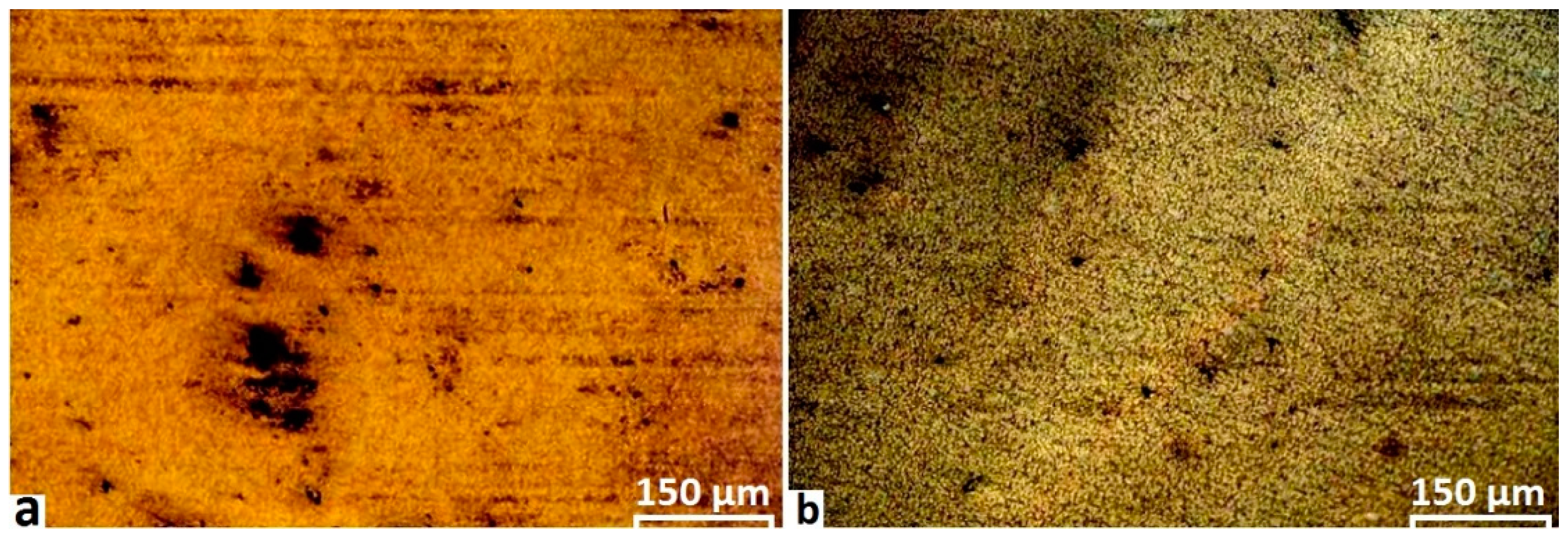
After polishing, samples were at first etched with conventional Keller’s and Kroll’s reagents (prepared per composition above) as an early comparison. The etching involved immersion of the polished specimens for 15 s at room temperature. Inspection showed that neither of these reagents clearly delineated the grain boundaries. This failing is consistent with the literature for this material. Despite increasing temperature and immersion time, there was no significant improvement in microstructure definition. As shown in Figure 2, even in severe chemical attacking of the surface and emergence of pitting, Keller’s and Kroll’s reagents could not produce good grain contrast for the weld samples.
The second part of the metallography method was focused on modification of reagents for macroetching and microetching.
We developed a number of candidate etchants, or more accurately a set of specific chemical solutions each with a sequence of application (process). The chemical perspective considered the following factors:
- NaOH is used to reveal grain structure. Likewise, HF.
- H3PO4 dissolves the Al2O3 oxide layer.
- CH3COOH is used to dilute the solution and reduce pitting attack. CH3COOH also has a positive effect in delineation of fine features (e.g., in stirring zone).
The process perspective considered the multiple steps. There is a need for a stage to remove the oxide film, followed by another stage to delineate the grain boundaries. Temporal or sequence factors that were considered were:
- Duration of immersion.
- Increasing the temperature up to 70 °C during etching.
- Immersion in ultrasonic bath can improve the uniform etching and also help remove the oxide layer. However, in our case, conventional immersion was used for all etchants.
Our optimisation method involved setting the chemical composition first, then etching until reaching an over-etched surface. We then progressively reduced the etching time and temperature until the surface features become clear.
The results are shown in Table 3, which describes the composition and other conditions of chemical solutions for different applications.
After etching, the samples were washed under a distilled water stream, rinsed in ethanol, and then dried with warm air. The macrostructure and microstructure of the etched samples were studied using stereographic and optical microscopy respectively. Results are reported below. The images are all for one welded sample, that has been re-polished and re-etched each time. We show that these various etchants are useful in elucidating different aspects of the microstructure.
3. Results
3.1. Macrostructure
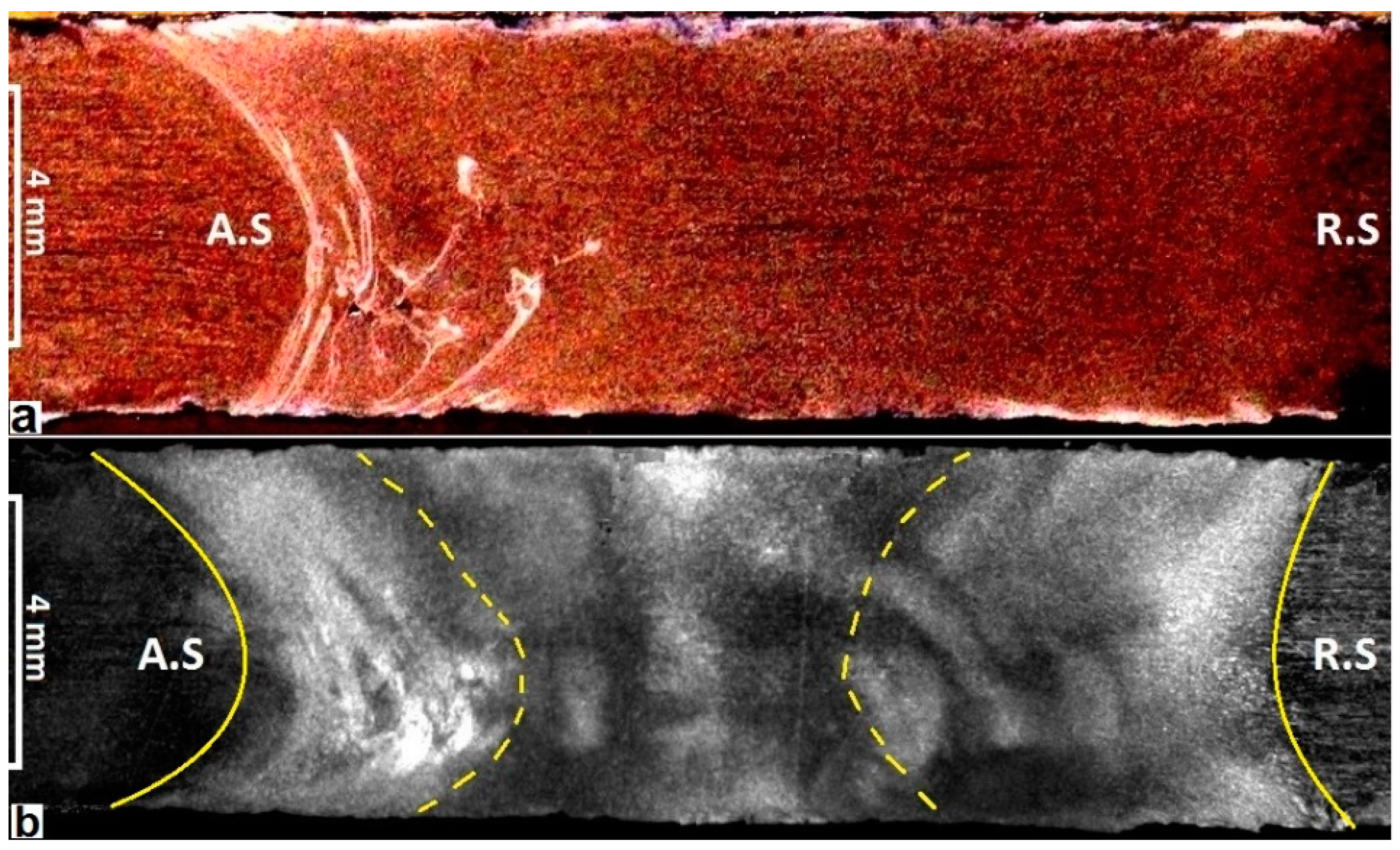
The macrostructure in the cross-section of a BFSW joint, processed by etchants A and etchant B are shown in Figure 3. The etchants readily reveal the S.Z hourglass pattern for the cross-section of the weld and the flow patterns. In Figure 3a the A.S border is more visible rather than the R.S side. Employing etchant B makes the position of the R.S border more visible, see Figure 3b. Even so, there is a blurring of the R.S border. This is attributed to the tendency for the tool to aggressively remove substrate material from the A.S and subsequently backfill the region with heavily worked material, hence making the A.S more defined by comparison with the R.S.
The flow eddies are best seen with etchant A, see Figure 3a. These features are attributed to the transportation mechanism inside the weld. The transportation mechanism is proposed to be as follows, extending on [16]. The flats on the tool scour out packets of material from the substrate—this work is most aggressive when conducted on the advancing side because this is where the combined linear and rotation motion is greatest relative to the substrate, hence this is also the hottest side. However, material is also scoured from the leading edge and the retreating side, as this is necessary for linear tool progression through the substrate. The rotation of the tool (clockwise from above), moves the material in the same rotational direction, which corresponds to a horizontal flow from right to left in the wake of the tool (which is always where the post-weld section is taken). Consequently, packets of material are moved round the weld from the advancing side, through the retreating side and back to the advancing side where the flow stalls. The stall occurs because the packets move into a region immediately downstream of the scouring action, while the flats scour out fresh material. The packets are thus packed into the downstream A.S, and the boundaries between these packets are believed to correspond to the bright lines in Figure 3a. According to this explanation, the flow of material is orthogonal to the bright lines, not along them. Hence, it is incorrect to call them flow lines—rather they are boundaries between flattened packets of material. It is generally evident, in this and other samples not shown here, that the lines are primarily vertical, which is consistent with the above explanation. Also, the spacing between lines is observed to be smaller closer to the advancing side wall, and this too is consistent with the packet transportation mechanism. An additional complexity is introduced by the threads on the tool. These transport the material downward [16], hence explaining why the packet boundaries are preferentially located at the bottom of the A.S.
We attribute the internal void defects, which are evident in the figure, to intermittent stalling of the flow. This is explained as the periodic passage of the flats on the tool causing momentary vacuum—hence the horizontal flow sometimes stalls into a low pressure situation, i.e., the packing pressure is absent.
The macroscopic aspects of the BFSW joint show no grain structure in the macro-etch. As subsequent results show, this is because of the fine grain size that arises in this material. However, to see these grains requires one of the micro-etch processes, which we describe next.
3.2. Microstructure
The etchant C was found to be effective at revealing the optical microstructure. Figure 4 shows the BFSW weld cross-section from B.M towards the S.Z for both of A.S and R.S. The etchant differentiates between the grains of the HAZ and TMAZ. In both cases the grain morphologies show a change in grain direction from columnar in the B.M, to an ultrafine structure in the S.Z.
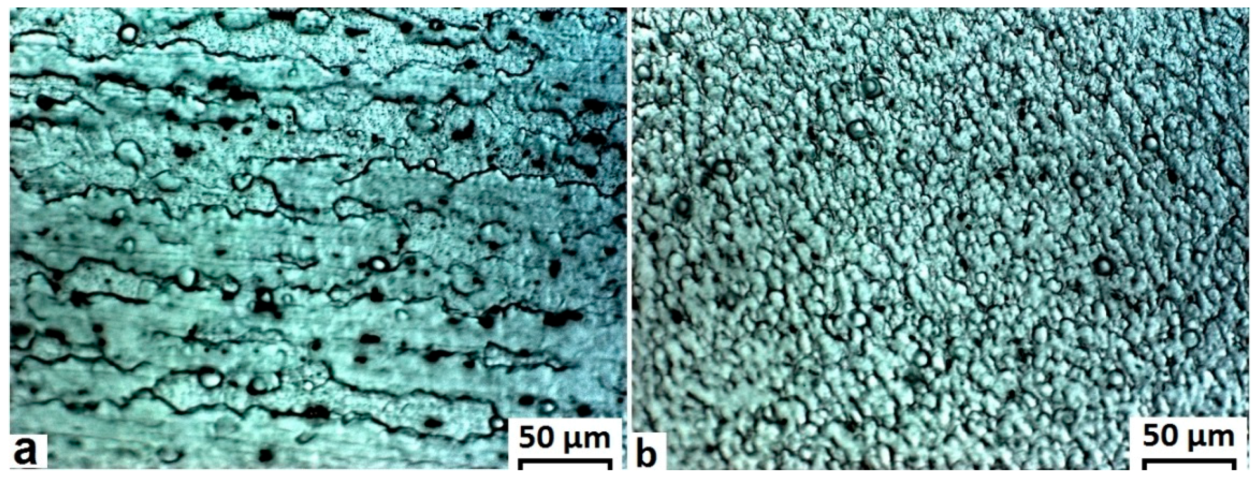
Higher magnification of the B.M and S.Z regions show the differences in grain morphology and size distribution, see Figure 5. Fine grains of the S.Z have spherical morphology with an average size less than 10 μm, while the grain size for the B.M is in the range of 100 μm. Also, the directional grains in the B.M (as a result of the primary rolling process on the sheets) have changed into equiaxed grains in the S.Z with a narrow range distribution. These features are indicative of dynamic recrystallization during the thermo-mechanical regime experiences in the welding process.
3.3. Grain Boundaries
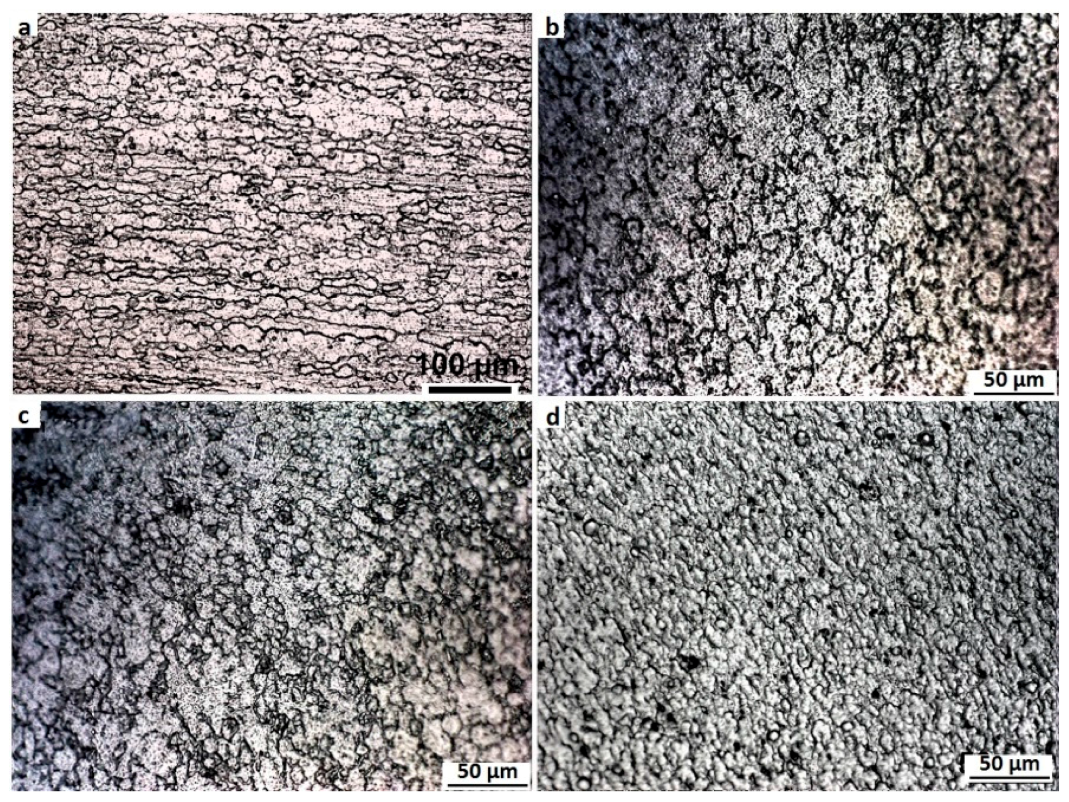
To obtain better contrast of the grain boundaries we developed etchant D. The microstructure of different regions of the BFSW weld are shown in Figure 6. Here the grain recrystallization and transition gradient of the morphological flow are more visible. A parallel columnar grain distribution indicating the rolling process in the base material is clear in Figure 6a. The HAZ shows a recrystallization of grains in Figure 6b. The TMAZ in Figure 6c shows a significant grain distortion which is attributed to the strain field.
It should be noted that there are some dark areas in the micrographs of Figure 6b,c in the HAZ and TMAZ, respectively. During the etching process, some stains are visible in the HAZ and the TMAZ. At first glance these might be assumed to be artefacts of over-etching. However, these are instead representative of flow features with different grain morphologies and sub-grain boundaries. They are unlikely to be precipitates, as precipitation in the stabilised microstructure of A6082-T6 alloy needs more temperature and time, higher than that provided by the BFSW process.
In the S.Z, Figure 6d, there is a fine homogeneity to the grain structure. This is a consequence of the recrystallization caused by the mechanical stirring mechanism. The stirring reduces grain size to less than 10 microns (see below) with low anisotropy (equiaxed grain structure).
3.4. Morphological Flow of Grains (Thermomechanical Distortion, Fragmentation, and Recrystallization)
For a finer scaled study of recrystallization and transition of grain morphology for the microstructure of A6082-T6, we developed several additional etchants.
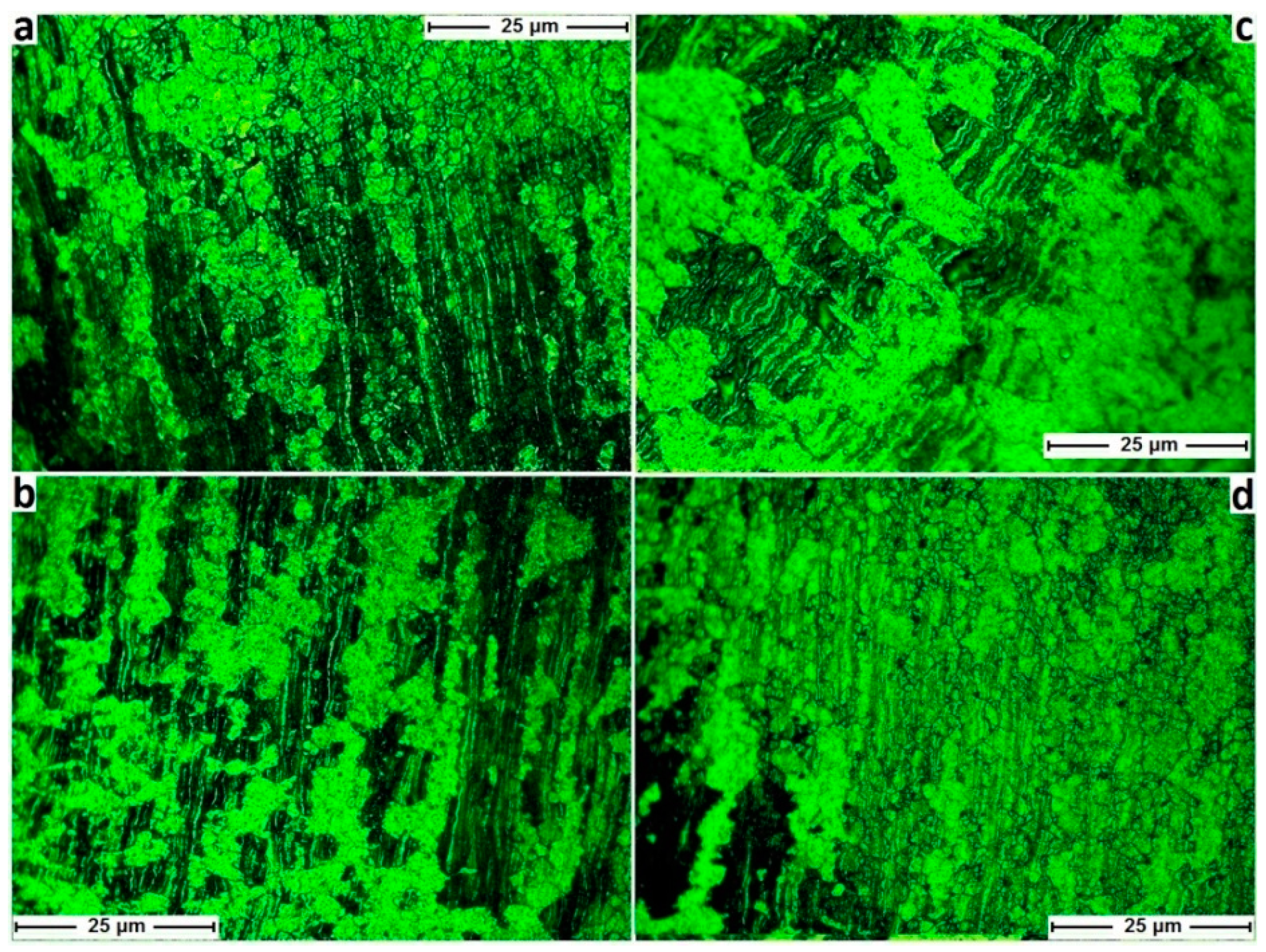
Etchant E is effective for microetching of the HAZ. Using a colour etchant can demonstrate the morphological flow of grain in an inhomogeneous transitional microstructure. Results are shown in Figure 7 for four different regions; A.S and R.S, and adjacent to the top shoulder and bottom shoulder. The micrographs show a layered structure with the colour contrast representing different gradients of the morphological flow for the grain distortion between the layers.
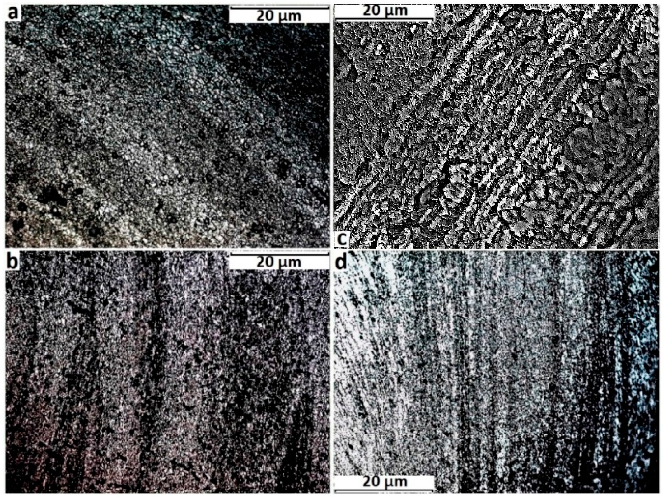
Etchant F was developed for microetching of the TMAZ. As before results are shown for four different regions; A.S and R.S, and adjacent to the top shoulder and bottom shoulder. See Figure 8. The dynamic nature of the mechanical and thermal trajectories causes each layer to have a different recrystallization history in comparison with the neighbouring layers.
Both in the HAZ and TMAZ, the micrographs show a layered structure. Comparison between different regions of the HAZ or TMAZ shows that generally the grains in the R.S are coarse and the layers are interwoven, while in A.S the layers have a more uniform structure. For further characterization of the grain orientation it would be appropriate to use X-ray diffraction (XRD) analysis or EBSD.
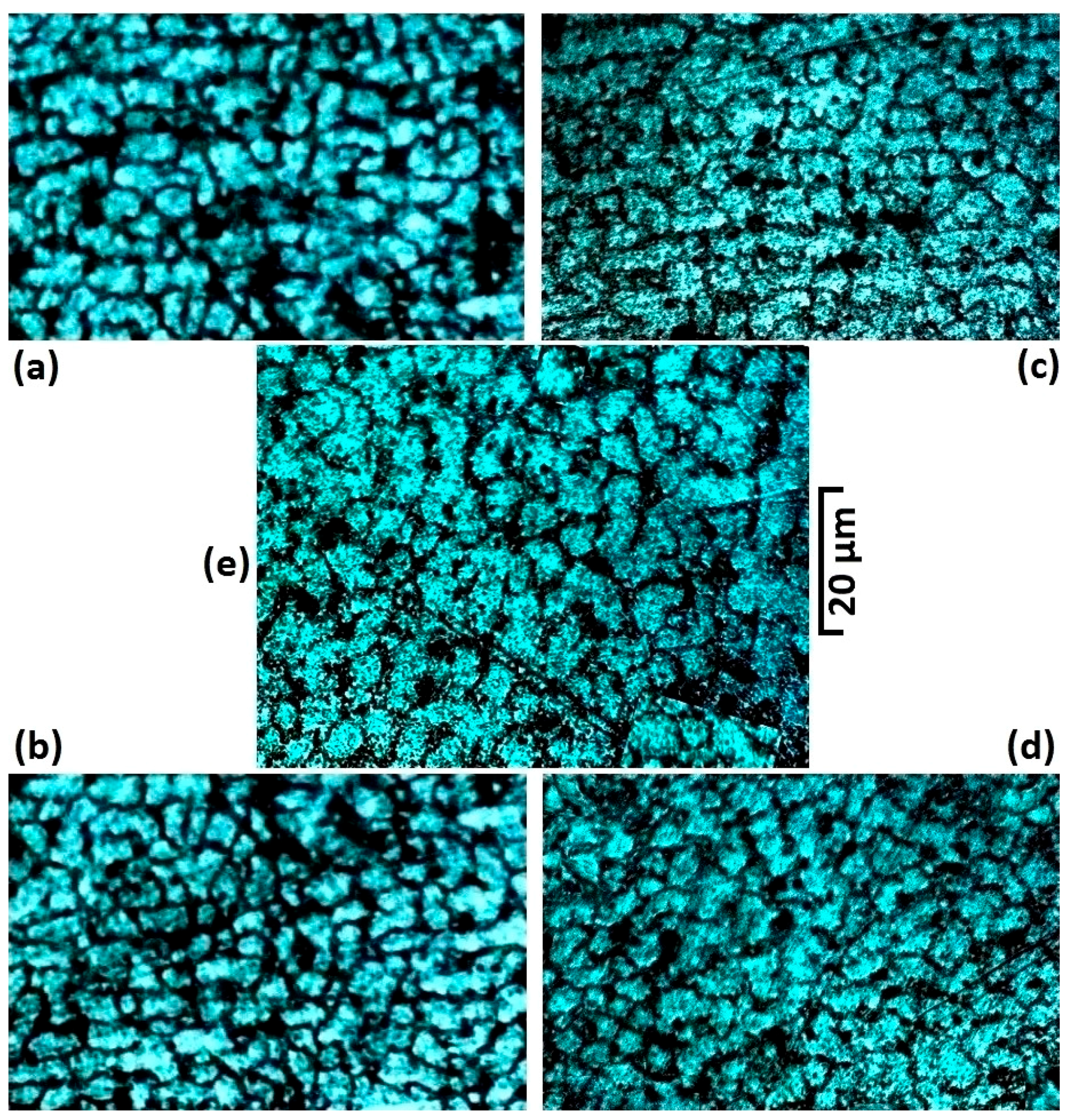
Etchant G was developed to reveal finer details about the individual grain boundaries, as opposed to the grain morphology. Results for different areas of the S.Z are shown in Figure 9. For all these micrographs, the equiaxed polycrystalline structure are visible with a narrow grain size range of distribution. The ultrafine equiaxed structure of the grains is attributed to the plasticisation and stirring of the welding process.
3.5. High Magnification Observations: Microflow Patterns, Polycrystalline Grain Distribution
We are interested in elucidating the microflow patterns for this material, which have not previously been shown in the literature. As shown above, the grains are of a fine size of 4–10 microns, which makes etching difficult. To address this problem, we developed etchants H and I. These are able to reveal the microflow patterns of the stirring (etchant H) and then the polycrystalline distribution of the microstructure for the same position (etchant I), see Figure 10. The microflow patterns are provided by etchant H being designed to have a high sensitivity to the stress-strain fields. The vortex style of the microflow shows the stirring motion of the process. The plasticised material is solidified after severe deformation under rotation and movement of the tool.
Figure 10c reveals a cusp pattern to the microflow, though this is only evident at higher magnification. The micrograph of Figure 10d processed by etchant I shows the polycrystalline patterns of the grain distribution for the same area and magnification as Figure 10c. This demonstrates that the different etchants selectively enhance different features in the material.
Figure 10d emphasises the polycrystalline morphology, and the results are interpreted as the grains having the same crystalline arrangement and grain size distribution. The cusp patterns of Figure 10c are resolved into grain boundaries in Figure 10d, indicating a coherent interface between the crystallites.
3.6. Coherent Interfaces
Inclusion particles are not uncommon in FSW [43]. These particles can be external inclusions which entered the weld region, probably by breaking of the oxide surface layer during the stirring process [43,44]. Sometimes the crushed particles from breaking of the oxide surface layer cannot escape from the shoulder’s rotation and are sucked into the stirring region. Slag inclusions in fusion welding likewise cause local interruptions in the microstructure [40,45]. These defects are distinguishable inside the weld region underneath the surface and can be identified by micro-cracks and streak-like segregation, with gas blisters in their immediate proximity [43,44,45]. As a result, these defects can be harmful for the structural integrity and may decrease the strength characteristics of the weld. However, the formation of a viable interface layer can provide a means for them to remain in the structure [43]. Accurate quantification of the interface layer is usually performed by means of electron microscopy and composition analysis; however here we used optical methods to examine two such interface layers in the sample.
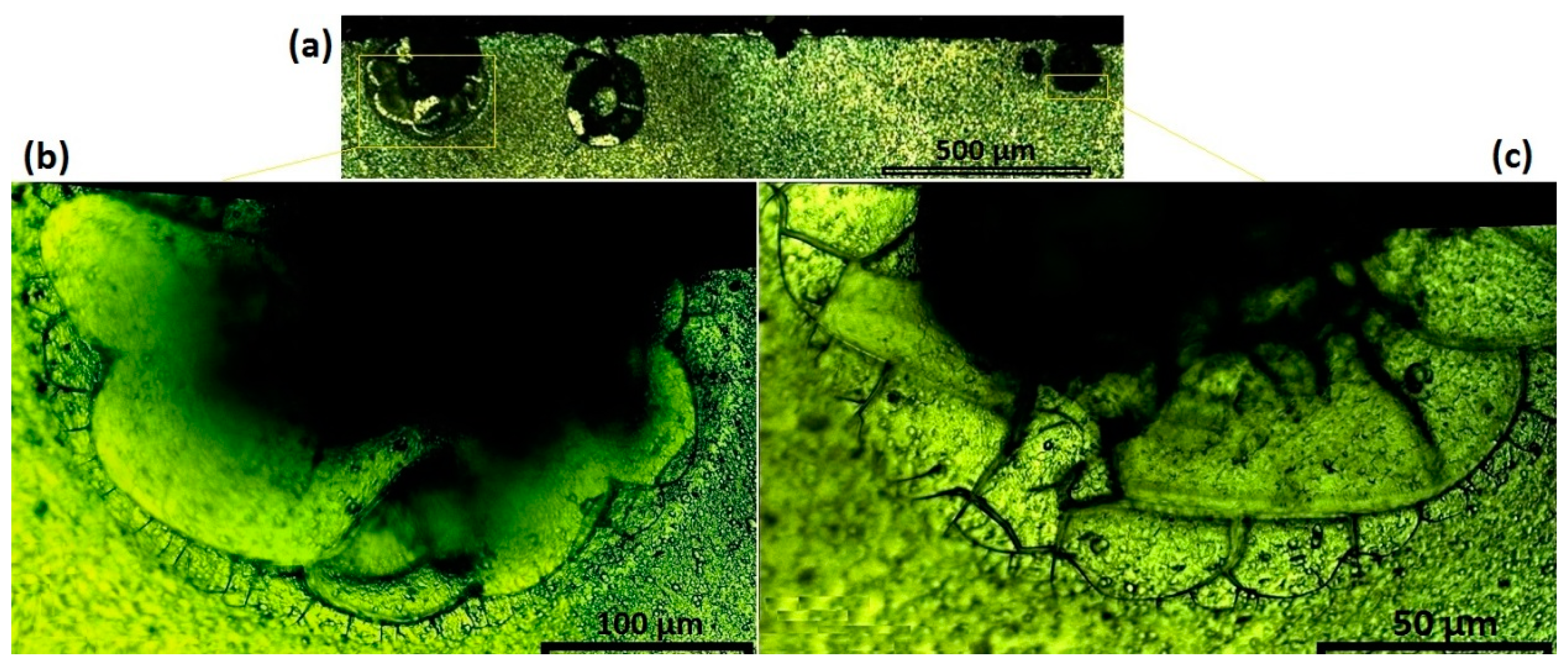
Using etchant I, Figure 11 reveals the coherent–incoherent interface for a defect at the surface of the welded region. This shows a clear lattice mismatch within the S.Z, close to the top shoulder position, see Figure 11a. Figure 11b,c show a higher magnification in the interface of the defect (dark mass) with the S.Z microstructure.
Our interpretation is that the defect comprises an inclusion combined with a gas blister. As the lattice parameter of the Al2O3 is different to Al solid solution, these oxide particles form non-metal inclusions [44]. The dark area in the figures is the gas blister, and is in some cases also associated with an inclusion in the centre (not easily evident).
In the specific case represented in Figure 11b,c, the interface comprises two sub-layers. Obviously, the defect itself has an incoherent interface with the parent phase (S.Z mass). Initially, the broad and curved layers surround the defect as the incoherent interface layer. This is similar to a primary adjustment between the external particle (oxide inclusion) and the solid solution lattice during the solidification. However, the interface bonding is non-uniform and can create discontinuity e.g., microcracks, during cooling. To increase the conformity, during the recrystallization process a secondary semi-coherent layer is formed between the wavy-shaped incoherent layer and the stirred mass to make a compromise between the S.Z microstructure and the external inclusion and gas blister. Microstructural study of the coherent/incoherent interfaces usually needs to be analysed by the transmission electron microscopy (TEM) technique, but here etchant I provides a quick measurement using optical microscopy.
4. Discussion
This work makes several novel intellectual contributions. The first is the development of a suite of etchant reagents for metallographic measurement of the friction-stir welded A6082-T6 alloy. The reagents have made it possible to reveal the grain boundaries and grain distribution with an ultrafine size within a BFSW weld region. This has not previously been shown to be possible in the literature for optical microscopy.
Observation of these micropatterns for FSW has not previously been shown using metallography methods, especially not for this grade of material. Development of these innovative etchants provides a means to create a high contrast between grains and grain boundaries; and this reveals micrographs which are usually visible only by electron microscope technology. Being able to show these with conventional optical microscopy is a novel contribution.
Another contribution is the elucidation of the grain size distribution and morphology for the BFSW weld, particularly the identification of polycrystalline structure. We found ultrafine grain microstructure with a narrow range of distribution in the stirring zone, and were able to visualise this at high magnifications. The grains in the stirring zone show a reduction up to 10 times finer than the base material grain size.
The present work shows that it is feasible to use optical microscopy, with suitable reagents, to inspect multiple aspects of the thermomechanical nature of the BFSW process, e.g., dynamic recrystallization, morphological flow of the grain distortion, and degree of interface coherency in solid solutions. Naturally, these phenomena can be comprehensively examined with the EBSD and electron microscopy techniques, nonetheless there is value in the simpler and less expensive optical methods shown here.
One issue is regarding the T6 heat treatment process and how it may be affected by the thermomechanical behaviour of BFSW. Our results show that the A6082-T6 columnar structure in the base material is changed to ultrafine equiaxed grains in the stirred zone. Since the microstructure has been changed with a massive increase in density of grain boundaries (the preferable position for hardening participates), there is uncertainty about the stability or otherwise of the T6 properties. The present work does not answer that question, though it does show that the BFSW process significantly affected the microstructure of the T6 heat treatment at the HAZ, TMAZ, and S.Z. Further work would be required to address this question, possibly using EBSD, phase characterization of participates in grain boundaries, or microhardness evaluation of different regions of the weld. This is left for future research.
Although the new etchants have demonstrably improved capability for microscopic observations, the process does require a fine surface polishing to show the microstructure details at higher magnifications. On its own, this is not a detriment as such finishes are generally expected for such magnifications. It will be noted that the etchants and associated procedures obviate the need for electropolishing or anodising, and hence provide a significant economy over those processes.
Warning—it should be noted that the etchants are more toxic than typical Al reagents. Hot immersion of samples may cause emission of toxic vapours, so the operator is advised to use a proper ventilation system and apply personal protective equipment (e.g., mask, polymer gloves, and safety glasses) to protect the skin, eyes, and respiratory system. The waste chemicals after etching should not be put down the drain because they can be hazardous for the environment.
A number of lines of enquiry for future research have been identified above, to which we can add additional ideas such as develop new reagents for colour metallography with sensitivity to the material flow and heat flux. Such reagents could provide a better understanding about the thermo-mechanical aspects of the process and reveal the failure mechanism of the flow regimes around defects, such as the tunnel void or kissing bond that is so prevalent in this grade of material.
5. Conclusions
A new suite of etchants has been developed for macro- and micro-etching of A6082-T6 bobbin welds. The etching provided microstructures reasonably free from pitting and observable with high magnification using optical microscopy. The microstructure of the grain boundaries was revealed for the different regions within the weld: HAZ, TMAZ, and S.Z. Results showed the grain size variation with distinct morphological patterns. This is an advancement on the level of detail apparent in the published literature, and makes it possible to conduct optical microscopy where previously only more expensive methods were suitable.
The polycrystalline structure of the S.Z showed a large decrease in grain size in comparison with the B.M. While the columnar grains of the B.M are about 100 micrometers, this is changed in S.Z to an equiaxed structure with average grain size under 10 microns. The grain boundaries and morphological flow gradient of grains from the B.M towards S.Z indicated a past recrystallization process which was attributed to the thermo-mechanical regime of the BFSW process. Etchants were able to elucidate microflow patterns and crystalline coherency of the interface. These etchants successfully supported optical visualisation that was capable of resolving structures at the ultrafine scale (~10 to micrometers, or 1000× magnification), with good contrast between grain and grain boundary.
Acknowledgments
The authors thank technical staff at the University of Canterbury for assistance with use of facilities, particularly Kevin Stobbs and Mike Flaws.
Author Contributions
The development of the etchants and determination of the sequence of application was carried out by Abbas Tamadon. The microscopy was performed by Abbas Tamadon, Dirk Pons, Kamil Sued, and Don Clucas supervised. The first draft of the paper was written by Abbas Tamadon, major edits by Dirk Pons. All authors contributed to writing the subsequent drafts, with Abbas Tamadon and Dirk Pons doing the final edits and D.P. the editorial correspondence.
Conflicts of Interest
The authors declare no conflict of interest.
References
- Martin, J.; Wei, S. Friction stir welding technology for marine applications. In Friction Stir Welding and Processing Viii; Springer: Berlin, Germany, 2015; pp. 219–226. [Google Scholar]
- Thomas, W.; Nicholas, E. Friction stir welding for the transportation industries. Mater. Des. 1997, 18, 269–273. [Google Scholar] [CrossRef]
- Thomas, W.; Wiesner, C. In Recent developments of FSW technologies: Evaluation of root defects, composite refractory tools for steel joining and one-pass welding of thick sections using self-reacting bobbin tools, Trends in Welding Research. In Proceedings of the 8th International Conference, Callaway Gardens Resort, Pine Mountain, GA, USA, 1–6 June 2008; p. 25. [Google Scholar]
- Thomas, W.; Wiesner, C.; Marks, D.; Staines, D. Conventional and bobbin friction stir welding of 12% chromium alloy steel using composite refractory tool materials. Sci. Technol. Weld. Join. 2009, 14, 247–253. [Google Scholar] [CrossRef]
- Threadgill, P.L.; Ahmed, M.; Martin, J.P.; Perrett, J.G.; Wynne, B.P. The Use of Bobbin Tools for Friction Stir Welding of Aluminium Alloys; Materials Science Forum; Trans Tech Publ: Stafa-Zurich, Switzerland, 2010; pp. 1179–1184. [Google Scholar]
- Chen, J.; Fujii, H.; Sun, Y.; Morisada, Y.; Ueji, R. Fine grained Mg–3Al–1Zn alloy with randomized texture in the double-sided friction stir welded joints. Mater. Sci. Eng. A 2013, 580, 83–91. [Google Scholar] [CrossRef]
- Moreira, P.; De Jesus, A.; Ribeiro, A.; De Castro, P. Fatigue crack growth in friction stir welds of 6082-T6 and 6061-T6 aluminium alloys: A comparison. Theor. Appl. Fract. Mech. 2008, 50, 81–91. [Google Scholar] [CrossRef]
- Moreira, P.; Santos, T.; Tavares, S.; Richter-Trummer, V.; Vilaça, P.; De Castro, P. Mechanical and metallurgical characterization of friction stir welding joints of AA6061-T6 with AA6082-T6. Mater. Des. 2009, 30, 180–187. [Google Scholar] [CrossRef]
- Sued, M.K. Fixed Bobbin Friction Stir Welding of Marine Grade Aluminium. Ph.D. Thesis, University of Canterbury, Christchurch, New Zealand, 2015. [Google Scholar]
- Adamowski, J.; Szkodo, M. Friction stir welds (FSW) of aluminium alloy AW6082-T6. J. Achiev. Mater. Manuf. Eng. 2007, 20, 403–406. [Google Scholar]
- Scialpi, A.; De Filippis, L.; Cavaliere, P. Influence of shoulder geometry on microstructure and mechanical properties of friction stir welded 6082 aluminium alloy. Mater. Des. 2007, 28, 1124–1129. [Google Scholar] [CrossRef]
- De Giorgi, M.; Scialpi, A.; Panella, F.; De Filippis, L. Effect of shoulder geometry on residual stress and fatigue properties of AA6082 FSW joints. J. Mech. Sci. Technol. 2009, 23, 26–35. [Google Scholar] [CrossRef]
- Gopi, S.; Manonmani, K. Microstructure and mechanical properties of friction stir welded 6082-T6 aluminium alloy. Aust. J. Mech. Eng. 2013, 11, 131–138. [Google Scholar] [CrossRef]
- Nandan, R.; Roy, G.; Lienert, T.; Debroy, T. Three-dimensional heat and material flow during friction stir welding of mild steel. Acta Mater. 2007, 55, 883–895. [Google Scholar] [CrossRef]
- Sued, M.; Pons, D.; Lavroff, J.; Wong, E.-H. Design features for bobbin friction stir welding tools: Development of a conceptual model linking the underlying physics to the production process. Mater. Des. (1980–2015) 2014, 54, 632–643. [Google Scholar] [CrossRef]
- Sued, M.K.; Pons, D.J. Dynamic interaction between machine, tool, and substrate in bobbin friction stir welding. Int. J. Manuf. Eng. 2016, 2016, 14. [Google Scholar] [CrossRef]
- Sharma, M.; Singh, A.; Singh, P.; Pathak, K.; Agnihotri, G. Experimental investigation of the effect of die angle on extrusion process using plasticine. Exp. Tech. 2011, 35, 38–44. [Google Scholar] [CrossRef]
- Neumann, T.; Zettler, R.; Vilaca, P.; Dos Santos, J.; Quintino, L. Analysis of self-reacting friction stir welds in a 2024-T351 alloy. Frict. Stir Weld. Process. IV 2007, 55–72. [Google Scholar]
- Dai, Q.; Wang, X.; Hou, Z.; Wu, J.; Shi, Q. Microcavities accompanying a zigzag line in friction stir welded A6082-T6 alloy joint. Sci. Technol. Weld. Join. 2015, 20, 68–74. [Google Scholar] [CrossRef]
- Davis, J.R. Aluminum and Aluminum Alloys; ASM International: Materials Park, OH, USA, 1993. [Google Scholar]
- Sasabe, S.; Matsumoto, T. Mechanical properties of A6082 welded joints with Nd–YAG laser. Weld. Int. 2012, 26, 351–359. [Google Scholar] [CrossRef]
- Aginagalde, A.; Gomez, X.; Galdos, L.; García, C. Heat treatment selection and forming strategies for 6082 aluminum alloy. J. Eng. Mater. Technol. 2009, 131, 044501. [Google Scholar] [CrossRef]
- Mohamed, A.; Samuel, F. A review on the heat treatment of Al-Si-Cu/Mg casting alloys. In Heat Treatment-Conventional and Novel Applications; InTech: Rijeka, Croatia, 2012. [Google Scholar]
- Svensson, L.-E.; Karlsson, L.; Larsson, H.; Karlsson, B.; Fazzini, M.; Karlsson, J. Microstructure and mechanical properties of friction stir welded aluminium alloys with special reference to AA 5083 and AA 6082. Sci. Technol. Weld. Join. 2000, 5, 285–296. [Google Scholar] [CrossRef]
- Esmaily, M.; Mortazavi, N.; Osikowicz, W.; Hindsefelt, H.; Svensson, J.; Halvarsson, M.; Martin, J.; Johansson, L. Bobbin and conventional friction stir welding of thick extruded AA6005-T6 profiles. Mater. Des. 2016, 108, 114–125. [Google Scholar] [CrossRef]
- Hilgert, J.; Schmidt, H.; Dos Santos, J.; Huber, N. Thermal models for bobbin tool friction stir welding. J. Mater. Process. Technol. 2011, 211, 197–204. [Google Scholar] [CrossRef]
- Hilgert, J.; dos Santos, J.F.; Huber, N. Investigation of the material shear layer in bobbin tool friction stir welding. Frict. Stir Weld. Process. VI 2011, 187–193. [Google Scholar]
- Hejazi, I.; Mirsalehi, S.E. Effect of pin penetration depth on double-sided friction stir welded joints of AA6061-T913 alloy. Trans. Nonferr. Metals Soc. China 2016, 26, 676–683. [Google Scholar] [CrossRef]
- Heurtier, P.; Jones, M.; Desrayaud, C.; Driver, J.H.; Montheillet, F.; Allehaux, D. Mechanical and thermal modelling of friction stir welding. J. Mater. Process. Technol. 2006, 171, 348–357. [Google Scholar] [CrossRef]
- Shen, J.; Wang, F.; Suhuddin, U.F.; Hu, S.; Li, W.; Dos Santos, J.F. Crystallographic texture in bobbin tool friction-stir-welded aluminum. Metall. Mater. Trans. A 2015, 46, 2809–2813. [Google Scholar] [CrossRef]
- Mrówka-Nowotnik, G.; Sieniawski, J. Influence of heat treatment on the microstructure and mechanical properties of 6005 and 6082 aluminium alloys. J. Mater. Process. Technol. 2005, 162, 367–372. [Google Scholar] [CrossRef]
- Panagopoulos, C.; Georgiou, E.; Gavras, A. Corrosion and wear of 6082 aluminum alloy. Tribol. Int. 2009, 42, 886–889. [Google Scholar] [CrossRef]
- Birol, Y.; Seracettin, A. Cooling slope casting to produce EN AW 6082 forging stock for manufacture of suspension components. Trans. Nonferr. Met. Soc. China 2014, 24, 1674–1682. [Google Scholar] [CrossRef]
- Xu, H.; Tang, H.; Liu, Z.; Xie, M.; Jiao, J. Microstructure and mechanical properties of 6082 aluminum alloy joints welded by MIG. Hot Work. Technol. 2010, 1, 042. [Google Scholar]
- Frigaard, Ø.; Grong, Ø.; Midling, O. A process model for friction stir welding of age hardening aluminum alloys. Metall. Mater. Trans. A 2001, 32, 1189–1200. [Google Scholar] [CrossRef]
- Vander Voort, G.; Manilova, E.P. Metallographic Etching of Aluminum and Its Alloys. Available online: http://www.georgevandervoort.com/metallography/specific/aluminum/20001307-metallographic-etching-of-aluminum-and-its-alloys.html (accessed on 10 October 2017).
- Vander Voort, G.F.; Lampman, S.R.; Sanders, B.R.; Anton, G.J.; Polakowski, C.; Kinson, J.; Muldoon, K.; Henry, S.D.; Scott, W.W., Jr. Asm Handbook; ASM International: Material Park, OH, USA, 2001. [Google Scholar]
- Myhr, O.; Klokkehaug, S.; Grong, O.; Fjær, H.; Kluken, A. Modeling of microstructure evolution, residual stresses and distortions in 6082-T6 aluminum weldments. Weld. J. 1998, 77, 286–292. [Google Scholar]
- Airod, A. Fundamental Analysis of the Deformation Behaviour of 5083 and 6082 Aluminium Alloys. Ph.D. Thesis, Ghent University, Gent, Belgium, 2006. [Google Scholar]
- Zipperian, D.C. Metallographic Handbook; Chief Technical Officier PACE Technologies: Tucson, AZ, USA, 2011. [Google Scholar]
- Sued, M.; Pons, D.; Lavroff, J. Compression Ratio Effects in Bobbin Friction Stir Welding. In Proceedings of the 10th International Friction Stir Welding Symposium, Beijing, China, 20–22 May 2014; pp. 1–19. [Google Scholar]
- Sued, M.; Tamadon, A.; Pons, D. Material flow visualization in bobbin friction stir welding by analogue model. In Proceedings of Mechanical Engineering Research Day 2017; Centre for Advanced Research on Energy: Melaka, Malaysia, 2017; pp. 368–369. [Google Scholar]
- Schneider, J.; Chen, P.; Nunes, A.C., Jr. Formation of oxides in the interior of friction stir welds. In Proceedings of the 11th International Friction Stir Welding Symposium, Cambridge, UK, 17–19 May 2016. [Google Scholar]
- Schneider, J.; Nunes, A.C., Jr. Origins of Line Defects in Self-Reacting Friction Stir Welds and Their Impact on Weld Quality. 2016. Available online: https://ntrs.nasa.gov/search.jsp?R=20160011068 (accessed on 1 January 2016).
- Kah, P.; Rajan, R.; Martikainen, J.; Suoranta, R. Investigation of weld defects in friction-stir welding and fusion welding of aluminium alloys. Int. J. Mech. Mater. Eng. 2015, 10, 26. [Google Scholar] [CrossRef]
Figure 1.
(a) Schematic of the bobbin friction stir welding (BFSW) process, (b) Geometric features of the bobbin tool.
Figure 1.
(a) Schematic of the bobbin friction stir welding (BFSW) process, (b) Geometric features of the bobbin tool.
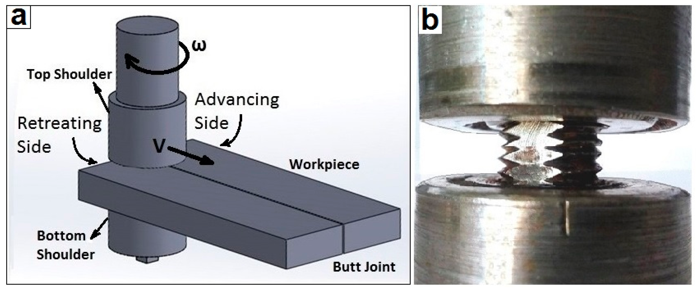
Figure 2.
Etched surface of the A6082-T6 weldments, (a) the Keller’s reagent and (b) Kroll’s reagent. These reagents are unsuccessful at elucidating the microstructure for this material.
Figure 2.
Etched surface of the A6082-T6 weldments, (a) the Keller’s reagent and (b) Kroll’s reagent. These reagents are unsuccessful at elucidating the microstructure for this material.

Figure 3.
Macrostructure of the cross-section of the BFSW joint for two different etchants, (a) etchant A, and (b) etchant B. The pictures belong to the same sample and the same location of the cross section, after re-polishing and re-etching the surface. The solid yellow lines demarcate the base material, and the dashed lines denote the approximate location of the zone directly affected by the pin and shoulder.

Figure 4.
Microstructure of the grain distribution in the advancing side (A.S, top) and the retreating side (R.S, bottom) of the A6082-T6 weld (processed by etchant C).
Figure 4.
Microstructure of the grain distribution in the advancing side (A.S, top) and the retreating side (R.S, bottom) of the A6082-T6 weld (processed by etchant C).
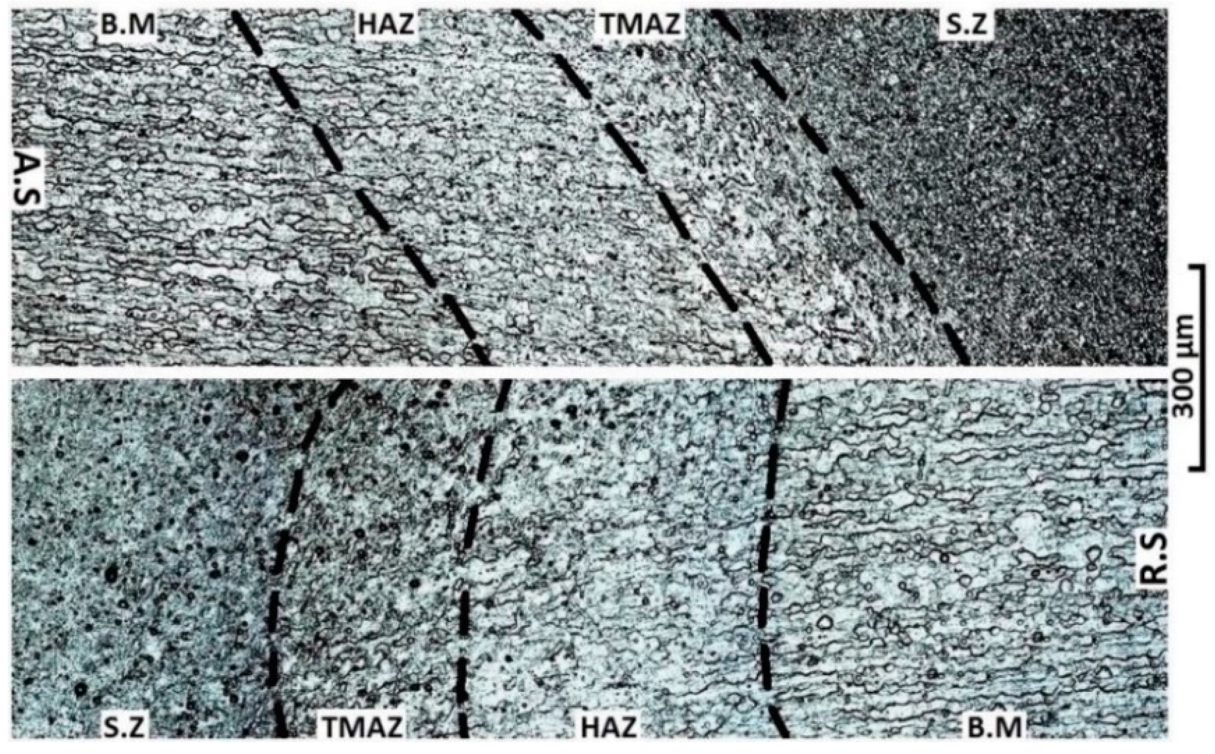
Figure 5.
A comparison between (a) the Base Metal (B.M) and (b) the Stir Zone (S.Z) for the A6082-T6 weld cross-section (processed by etchant C).
Figure 5.
A comparison between (a) the Base Metal (B.M) and (b) the Stir Zone (S.Z) for the A6082-T6 weld cross-section (processed by etchant C).

Figure 6.
Microstructure of different regions of a BFSW A6082-T6 weld processed by etchant D; (a) B.M; (b) Heat Affected Zone (HAZ); (c) Thermo-mechanical Affected Zone (TMAZ); (d) S.Z.
Figure 6.
Microstructure of different regions of a BFSW A6082-T6 weld processed by etchant D; (a) B.M; (b) Heat Affected Zone (HAZ); (c) Thermo-mechanical Affected Zone (TMAZ); (d) S.Z.

Figure 7.
Morphological transition of grain flow in the HAZ processed by etchant E: (a) top shoulder-A.S; (b) bottom shoulder-A.S; (c) top shoulder-R.S; and (d) bottom shoulder-R.S.
Figure 7.
Morphological transition of grain flow in the HAZ processed by etchant E: (a) top shoulder-A.S; (b) bottom shoulder-A.S; (c) top shoulder-R.S; and (d) bottom shoulder-R.S.

Figure 8.
Morphological transition of grain flow in the TMAZ processed by etchant F: (a) top shoulder-A.S; (b) bottom shoulder-A.S; (c) top shoulder-R.S; and (d) bottom shoulder-R.S.
Figure 8.
Morphological transition of grain flow in the TMAZ processed by etchant F: (a) top shoulder-A.S; (b) bottom shoulder-A.S; (c) top shoulder-R.S; and (d) bottom shoulder-R.S.

Figure 9.
Equiaxed polycrystalline microstructure in different areas of the S.Z, (a) top shoulder-A.S; (b) bottom shoulder-A.S; (c) top shoulder-R.S; (d) bottom shoulder-R.S; and (e) middle of S.Z (all processed by etchant G). The average grain size in the S.Z is smaller than 10 μm, but in the centre of the S.Z the grains are larger.

Figure 10.
The micro-patterns in the stirring zone for BFSW A6082-T6 at progressive magnification (a–c) using etchant H, and (d) the mosaic crystallites for the same location of (c) processed by etchant I. The yellow rectangles show the progressive area of magnification from (a) to (b) and then (c,d).
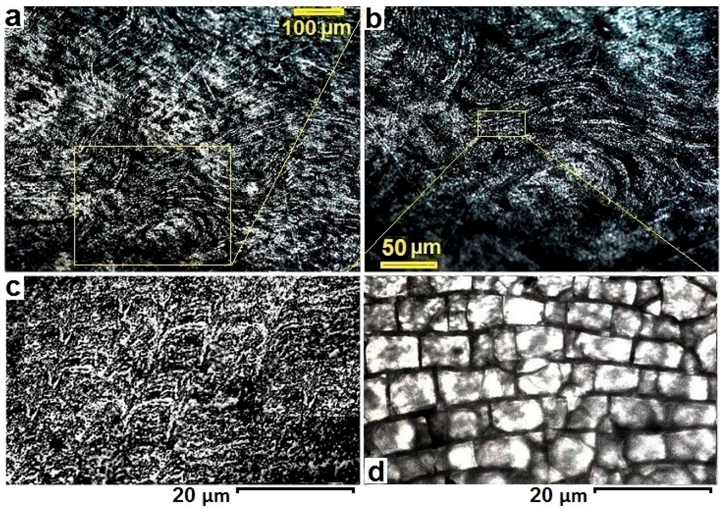
Figure 11.
Interface layer between the inclusion defect (external oxide particles) and the parent phase of the weld (S.Z mass). (a) Oxide inclusions at the sub-shoulder location of the S.Z. (b,c) Enlarged details of yellow rectangles in (a) showing the crystalline incoherent-semicoherent interfaces of the oxide inclusions with the S.Z lattice. All images processed by etchant I.

Table 1.
Element composition of the A6082 Al alloy (wt %) [20].
Table 1.
Element composition of the A6082 Al alloy (wt %) [20].
| Chemical Element | % Present |
|---|---|
| Silicon (Si) | (0.70–1.30) |
| Magnesium (Mg) | (0.60–1.20) |
| Manganese (Mn) | (0.40–1.00) |
| Iron (Fe) | (0.0–0.50) |
| Chromium (Cr) | (0.0–0.25) |
| Zinc (Zn) | (0.0–0.20) |
| Titanium (Ti) | (0.0–0.10) |
| Copper (Cu) | (0.0–0.10) |
| Other (Each) | (0.0–0.05) |
| Other (total) | (0.0–0.15) |
| Aluminium (Al) | Balance |
Table 2.
Parameters of the welding process for the A6082-T6 samples.
| Parameter | Value |
|---|---|
| DShoulder (mm) | 21 |
| DPin (mm) | 7 |
| DShoulder/DPin | 3 |
| Plate Thickness (mm) | 6 |
| Compression Ratio | 3.75% |
| Spindle rotational speed ω (rpm) | 600 |
| Feed rate V (mm/min) | 400 |
| Thread Pitch (mm) | 1.75 |
| Number of Threads | 4 |
Table 3.
Different groups of reagents with separate sequences of processing.
| Name of Etchant | Etching Type | Pre-Etching | Etchant Composition |
|---|---|---|---|
| A | General Macrostructure | - | 30.0 g NaOH + 100 mL ethanol (3 min, 50 °C) |
| B | General Macrostructure | - | 2.5 mL HF + 2.5 mL HCl + 95 mL H2O (30 s, 50 °C) |
| C | General Microstructure | - | 0.5 g (NH4)2MoO4 + 3.0 g NH4Cl + 1 mL HF + 18 mL HNO3 + 80 mL H2O (90 s, 70 °C) |
| D | G.B Microstructure | 20 g NaOH + 80 mL H2O (20 s, 50 °C), | Etchant C (60 s, 70 °C) |
| E | HAZ Microstructure | 20 g NaOH + 80 mL H2O (20 s, 50 °C), then: 30 mL H3PO4 + 70 mL ethanol (20 s, 50 °C) | 10 g CrO3 + 2 g Na2SO4 + 10 mL HNO3 + 10 mL CH3COOH + 1 mL HF + 80 mL H2O (60 s, 70 °C) |
| F | TMAZ Microstructure | 20 g NaOH + 80 mL H2O (20 s, 50 °C), then: 30 mL H3PO4 + 70 mL ethanol (20 s, 50 °C) | Etchant E (60 s, 70 °C), then: 15 mL CH3COOH + 85 mL H2O (15 s, 70 °C), then: 15 mL H3PO4 + 85 mL H2O (15 s, 70 °C), |
| G | S.Z Microstructure | 20 g NaOH + 80 mL H2O (40 s, 50 °C) | 10 mL HCl + 40 mL HNO3 + 2.5 mL HF + 12 g CrO3 + 10 mL CH3COOH + 50 mL H2O (60 s, 70 °C), then: 20 mL CH3COOH + 80 mL H2O (20 s, 70 °C), then: 20 mL H3PO4 + 80 mL H2O (20 s, 70 °C), |
| H | Micro-flow Patterns | - | 2 mL HF + 2 mL HBF4 + 10 mL HNO3 + 20 mL CH3COOH + 33 mL H2O + 33 mL ethanol (90 s, 70 °C) |
| I | Polycrystalline Structure | 20 g NaOH + 80 mL ethanol (20 s, 50 °C), then: 20 mL H3PO4 + 80 mL ethanol (20 s, 50 °C) | 2 mL HF + 2 mL HBF4 + 5 mL HNO3 + 30 mL CH3COOH + 60 mL ethanol (90 s, 70 °C) |
© 2017 by the authors. Licensee MDPI, Basel, Switzerland. This article is an open access article distributed under the terms and conditions of the Creative Commons Attribution (CC BY) license (http://creativecommons.org/licenses/by/4.0/).
Share and Cite
MDPI and ACS Style
Tamadon, A.; Pons, D.J.; Sued, K.; Clucas, D. Development of Metallographic Etchants for the Microstructure Evolution of A6082-T6 BFSW Welds. Metals 2017, 7, 423. https://doi.org/10.3390/met7100423
AMA Style
Tamadon A, Pons DJ, Sued K, Clucas D. Development of Metallographic Etchants for the Microstructure Evolution of A6082-T6 BFSW Welds. Metals. 2017; 7(10):423. https://doi.org/10.3390/met7100423
Chicago/Turabian StyleTamadon, Abbas, Dirk J. Pons, Kamil Sued, and Don Clucas. 2017. "Development of Metallographic Etchants for the Microstructure Evolution of A6082-T6 BFSW Welds" Metals 7, no. 10: 423. https://doi.org/10.3390/met7100423
Note that from the first issue of 2016, this journal uses article numbers instead of page numbers. See further details here.