Article

The Effect of Vibration during Friction Stir Welding on Corrosion Behavior, Mechanical Properties, and Machining Characteristics of Stir Zone

1
Faculty of Engineering, University of Kashan, Kashan 8731753153, Iran
2
School of Engineering, Faculty of Science, Engineering and Built Environment, Deakin University, Geelong 3216, Australia
*
Author to whom correspondence should be addressed.
Metals 2017, 7(10), 421; https://doi.org/10.3390/met7100421
Submission received: 10 July 2017 / Revised: 18 September 2017 / Accepted: 26 September 2017 / Published: 10 October 2017

Abstract

:
Different methods have been applied to refine various characteristics of the zone (or nugget) obtained by friction stir welding (FSW). In the current research, joining components are vibrated normal to the weld line during FSW to refine the zone microstructure. This process is described as friction stir vibration welding (FSVW). The effect of FSVW on mechanical properties, corrosion behavior, and machining characteristics of the zone are investigated. Al5052 alloy specimens are welded using FSW and FSVW processes and their different characteristics are compared and discussed. The results show that the strength and ductility of the welded parts increase when the vibration is applied. The outcomes also show that corrosion resistance of the nugget for FSV-welded specimens is lower than FS welded samples, and machining force of the former specimens is higher than the latter ones. These are related to smaller grain size in the zone of FSV-welded specimens compared to FS welded parts. Smaller grain size leads to a greater volume fraction of grain boundaries and, correspondingly, higher strength and hardness, as well as lower corrosion resistance.

1. Introduction

Friction stir welding (FSW) is a solid-phase joining process which has the various applications in industry such as aerospace and automotive. In this process a rotating welding tool is traversed along the joint path between the workpieces to be joined [1]. The rotation of the tool generates frictional heat, which softens the joining materials around the weld line. The combined transverse and rotation motions of the tool mix the softened material in the joining area and a high-quality welded joint is obtained [2,3]. FSW is especially suitable for the welding of non-ferrous metals with low melting points, such as aluminum, magnesium, copper and brass. However, this process has also been applied for welding of high melting point metals, like titanium and steel [4].
The temperature during FSW is low and below the melting point of the parts being joined. In this regard, mechanical defects, such as pores and cracks which are normally observed during fusion welding and solidification of the weld pool are avoidable [5,6]. However, the geometrical features of some FSW processes, such as the formation of hooks and keyholes are unavoidable. FSW is an environmentally-friendly welding process. The energy consumption in this method compared to other welding processes is low, and no specific chemical pretreatment of the material is needed. No filler materials or shielding gasses are needed in this method which is another advantage [7,8]. FSW has a great applicability for joining of dissimilar materials especially those with a high difference in melting point and thermal expansion-contraction coefficient. Consideration of different requirements for the joining of dissimilar metals has encouraged the researchers and industries to apply friction techniques, such as friction welding, FSW, friction drilling, and form tapping [9,10,11].
Inappropriate values of FSW parameters, namely, traverse speed, rotational speed, and tilt angle, normally lead to defect formation in weldments. In this regard, determining the appropriate values of these welding parameters is imperative. Process parameter optimization through trial and error is time and cost consuming. Different methods were applied for optimization. According to these methods, a design for experiments is done and based on statistical analyses optimized values are obtained. Elanchezhian et al. [12] applied a Taguchi L9 orthogonal array for the design of experiments and finally used ANOVA statistical tool to reveal the optimum values of parameters for FS welding of AA6061 and AA8011 aluminum alloys. Jafari et al. [13] applied the Taguchi method for experiment design and RSM for determining the optimum values of process parameters. Characteristics of joints made by FSW are the subject of numerous studies. Peel et al. [14] evaluated the microstructure, mechanical properties of aluminum AA5083 FS welds produced under varying conditions, and found that the weld properties were governed mainly by the thermal input into the weld region rather than mechanical deformation. Kwon et al. [15] studied the effect of tool rotation speed on mechanical properties of joints developed between 5052 aluminum alloys. They found that the grain size in the FSW zone (also known as the nugget) is smaller than that of the base metal and it increases with an increase of the tool rotation speed. They also found that hardness in the FSW zone was higher than that of base metal. Kumar et al. [16] studied the effect of retrogression and re-aging (RRA) post weld heat treatment and B4C nanoparticle addition on the microstructure, hardness, and pitting corrosion of the FSW zone during the friction stir welds of AA7075 alloy. They found that RRA improved the pitting corrosion resistance, but hardness was slightly decreased. The results also showed that significant improvement in pitting corrosion resistance was achieved with the addition of boron carbide powder. Maggiolino and Schmid [17] compared the corrosion resistance of AA6082T6 and AA6060T5 joints made by FSW and metal inert gas welding processes. Tests were conducted putting the welded and polished samples in an acid salt solution. The attack was localized and an index referred to the pit density was used for the comparison. They found that the friction stir welded samples had better pitting corrosion resistance than the metal inert gas welded samples. This was related to gas porosity formation in the weld bead and more activity of the thermally-affected zone. They also observed that no large differences in the corrosion resistance between the base material and the welded joints existed for the FSW.
Serio et al. [18,19] studied the FSW process and evaluated the effect of process parameters, as well as the welding tool rotation speed and the welding tool traverse speed on the thermal and mechanical behavior of 5754-H111 plates joined by FSW. They correlated the process parameters and the thermal and mechanical properties of joints by statistical analysis and found that infrared thermography can be used to on-line monitoring of the FSW process to evaluate the quality of joints. Kim et al. [20] studied the fatigue behavior of FSW and gas metal arc welding (GMAW) butt welded joints of AA6005-T5 extruded sheets. They found that the strength of the FSW joints was notably better than GMAW ones and the fatigue resistance increased by decreasing tool welding speed and tool rotating speed and increasing the tilt angle. Urso et al. [21] studied the fatigue behavior of FS welded butt joints of AA6060-T6 by using crack growth tests. Their results showed that the fatigue crack growth rate of welded specimens was lower than the base material. This was related to the effect of compressive residual internal stress induced by FSW.
Different studies have been carried out to modify the microstructure and various properties of the zone formed by FSW. FSW assisted by laser [22], ultrasonic vibration [23], and electrical current [24] are some of the modifications which increase the FSW tool life and refine the zone microstructure. In the current research, grain size in the zone is refined through friction stir vibration welding (FSVW). In this process, joining parts are vibrated normal to the weld line during FSW. Formability, corrosion resistance, and machining behavior of joints made by FSVW are compared with FSW parts and the mechanical and materials view points of the differences are comprehensively discussed.

2. Materials and Methods

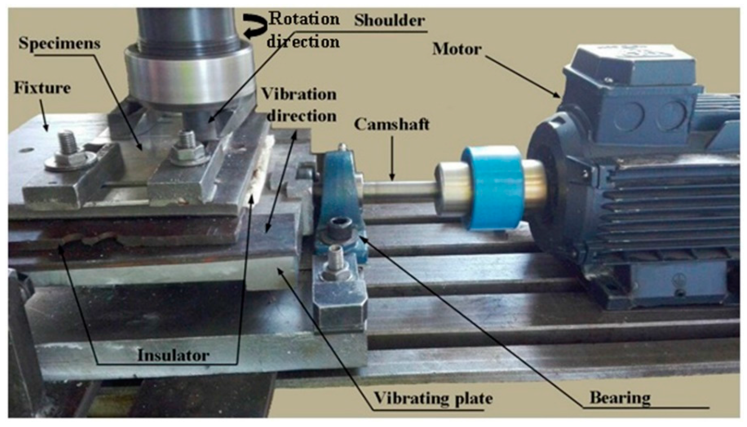
2.1. Welding Process

Al5052 alloy sheet with 3 mm in thickness was cut into rectangular specimens with dimensions of 150 mm × 50 mm. The longitudinal edges of the specimens were deburred and cleaned of oil and grease and the specimens were fixed on a fixture in a butt position.
The machine used for FSVW is shown in Figure 1. The power of electrical motor is transformed into linear motion by a vibrating plate through the camshaft. The workpieces were vibrated through the vibrating plate in a direction normal to the weld line with a movement amplitude of 0.5 mm.
The welding tool (Figure 2) consists of two parts, pin and shoulder made by tungsten carbide and M2 steel with 65 HRC hardness, respectively. A schematic design and the geometry for the applied tool are presented in Figure 2.
Welding conditions for FSW and FSVW processes are presented in Table 1. It is observed that, except the presence of vibration for FSVW, the welding conditions are the same for both processes. Vibration frequency for FSVW process was 33 Hz. Tilt angle and tool plunge depth for all welding conditions were considered 2° and 2.7 mm, respectively.
The microstructure was characterized using metallography based on ASTM-E3-11 [25] and application of light optical microscopy (LOM, Olympus, Tokyo, Japan). The etchant consisted of 2.58 vol % picric acid, 10.82 vol % acetic acid, 10.82 vol % water, and 75.78 vol % ethanol was applied for 5 s to reveal the microstructure.
The mechanical properties of the joints were assessed using a uniaxial tensile test according to ASTM-E8 [25]. Sub-sized tensile test samples normal to the weld line were prepared from the welded specimens using electro discharge machining (wire cut), while the FSW zone was in the middle of the dog bone samples. To check the repeatability and precision for each welding condition, three tensile test samples were prepared. Figure 3 shows schematic design of tensile test specimen with dimensions and Figure 3b,c present tensile test specimens for FS- and FSV-welded specimens, respectively. Tensile tests were carried out using the Instron 5582 Universal tester (Instron, Boston, MA, USA) with a 100 kN load frame and equipped with an extensometer. The cross speed during tensile testing was 1 mm/min.

2.2. Corrosion Test

Corrosion behaviors of the samples were studied using electrochemical impedance spectroscopy (EIS) and polarization techniques. The tests were performed on the cross-sections of the welded samples with a surface area of 0.15 cm2. A platinum electrode and an Ag/AgCl electrode were used as the counter and reference electrodes, respectively. The electrochemical tests were performed in a 3.5% NaCl distilled water solution at a temperature of 25 °C using a µ-AUTOLAB III potentiostat (Metrohm, Utrecht, The Netherlands). The scan rate in the polarization tests was 0.2 mV/s. EIS tests were performed in a frequency range from 100 kHz to 10 MHz with a voltage amplitude of 20 mV in the open circuit potential.

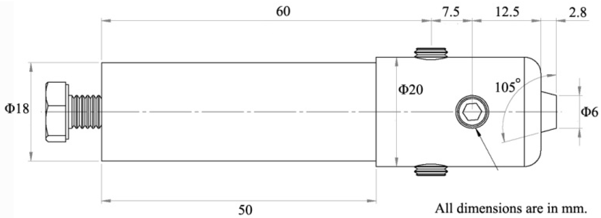
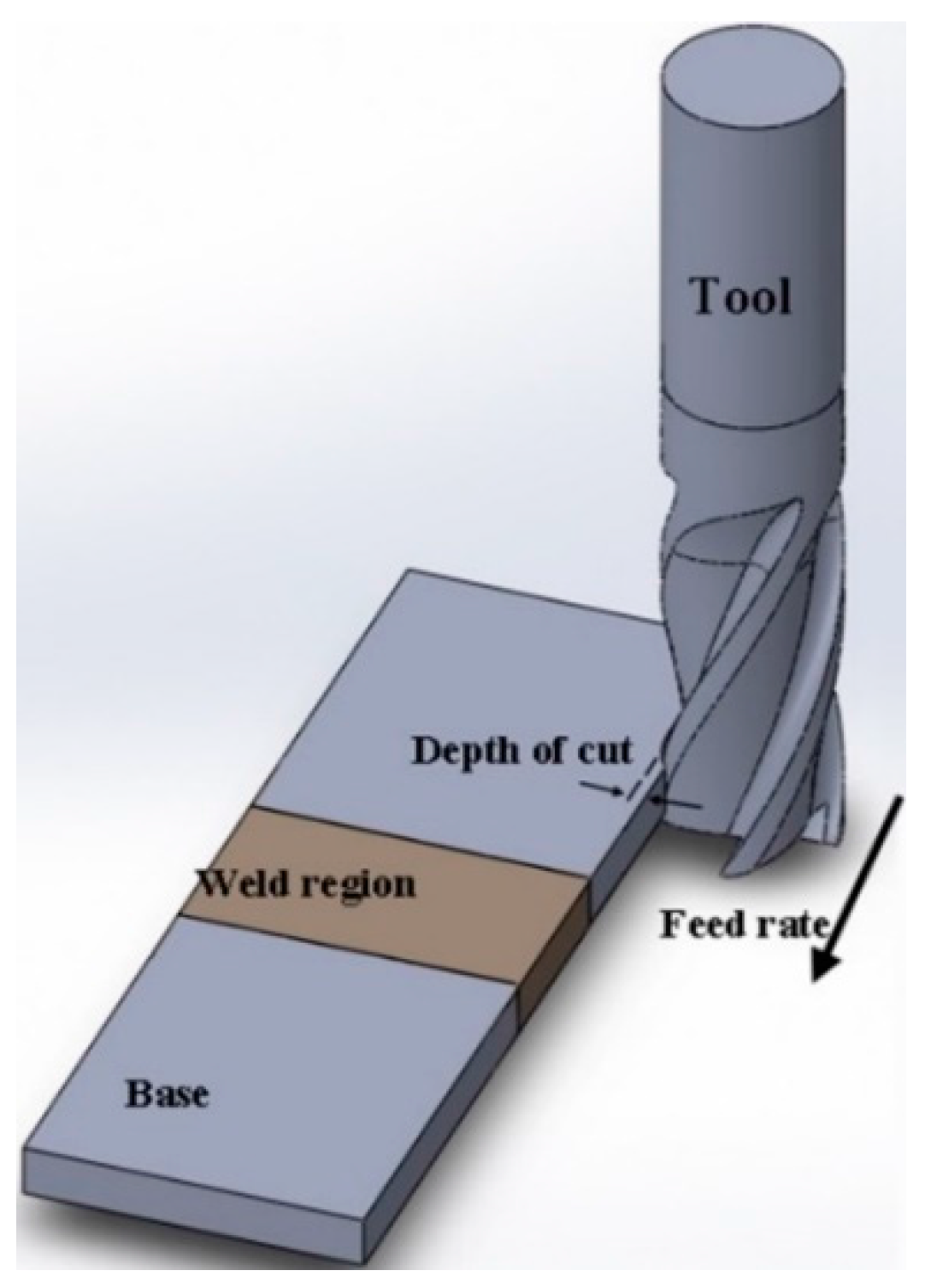
2.3. Machining Setup

Machining characteristics of three samples, namely base material, zones of FS welded and FSV-welded samples were studied. Longitudinal grooves along the edge of the samples were machined and cutting forces were measured. The rectangular samples with dimensions of 100 mm × 50 mm and thickness of 3 mm were clamped on the fixture to perform stable cutting along the longitudinal edge and avoid machining vibration that may affect the cutting force and machining process. For welded specimens, the longitudinal edge was normal to the weld line. A schematic design for the cutting process is presented in Figure 4. Cutting forces were measured during milling at a sampling rate of 5 µs by using a Kistler 5070 dynamometer (Kistler, Winterthur, Switzerland) mounted on the machine table. A helical end-mill made from high speed machining (HSM) steel was used as a cutting tool. The specifications of the mill tool are provided in Table 2 and the milling conditions are presented in Table 3.

3. Results and Discussion
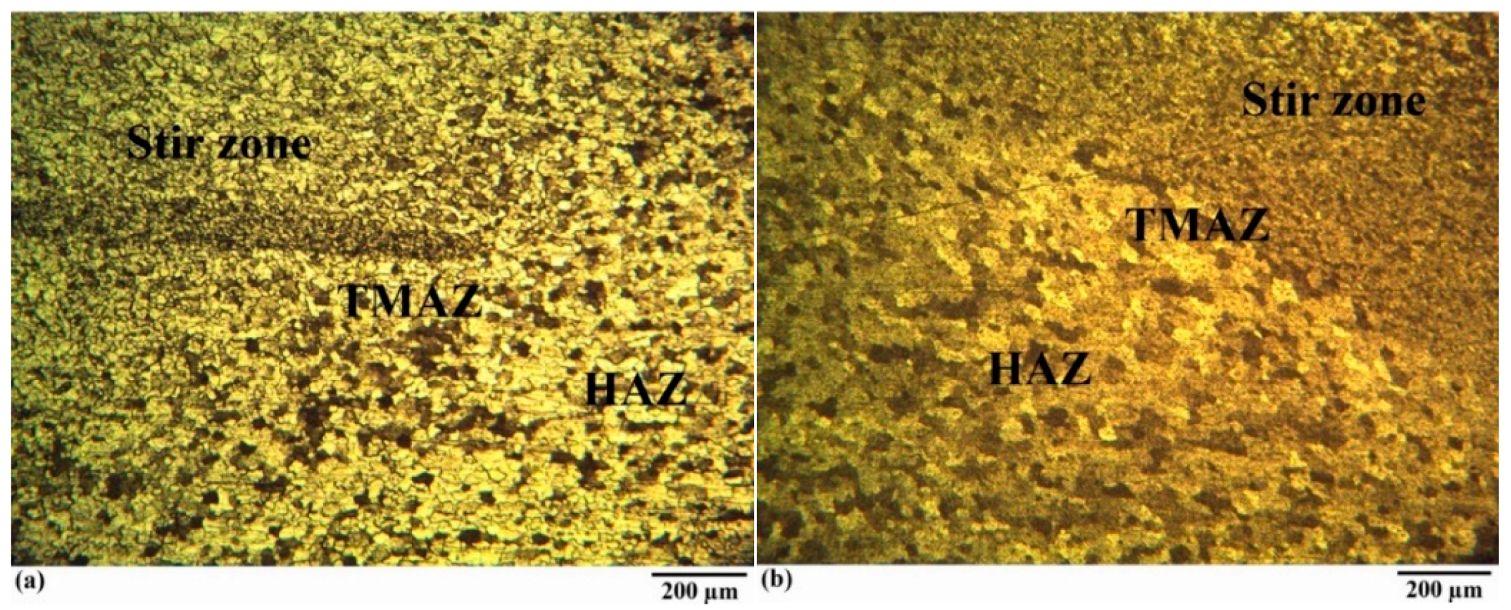
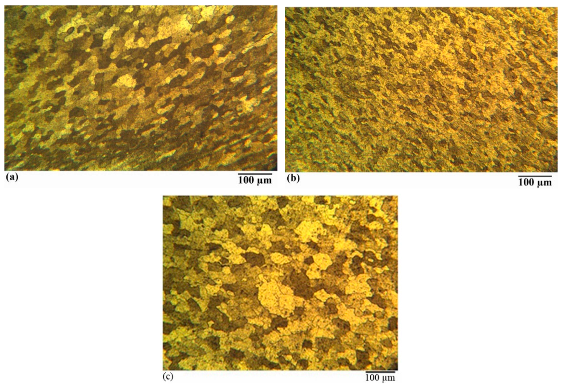
3.1. Microstructure

Microstructures of welded regions consisting of FSW zone, TMAZ, and HAZ for FS- and FSV-welded specimens are presented in Figure 5. Microstructures of zones for both welded specimens, as well as base material, are represented in Figure 6 with more magnification.
It is observed that the FSW zone grain size for welded specimens are smaller than the base material and zone grain size in FSV-welded samples is smaller than that in FS welded samples. These both can be related to the effect of dynamic recovery and recrystallization. It is known [26,27] that dynamic recovery and recrystallization are the main mechanisms for grain refinement during FSW; although, it seems that presence of vibration enhances these phenomena. According to Kaibyshev [26,27], with increase of strain, dislocations are generated and a rapid multiplication of dislocations occurs. A progressive increase in dislocation density with increasing strain leads to three-dimensional arrays of low-angle grain boundaries (LABs) which transform to high-angle grain boundaries (HABs) during FSW. Individual segments of HABs replace sub-grains evolved at small strains and accordingly grain size refinement occurs. Presence of vibration partially increases the temperature in the weld region [28] and additionally enhances the work hardening and leads to more strain in the zone. FSW is a severe plastic deformation process. During this process, due to the friction between the tool and the workpiece, the material is soft and can be deformed easily. The rotation of tool transfers the material from the advancing side to the retreating side and, thus, deforms the material. The presence of vibration, in addition to stirring, increases deformation because it adds an additional movement to the material. In this regard, the material deforms more and more strain occurs in the FSW zone.
It has been known that when annealed crystals are deformed, a rapid multiplication of dislocations and a progressive increase in dislocation density with increasing strain is observed [29]. The increment of dislocation density, by applying the vibration, enhances the dynamic recrystallization and decreases the zone grain size in FSV-welded samples [30].

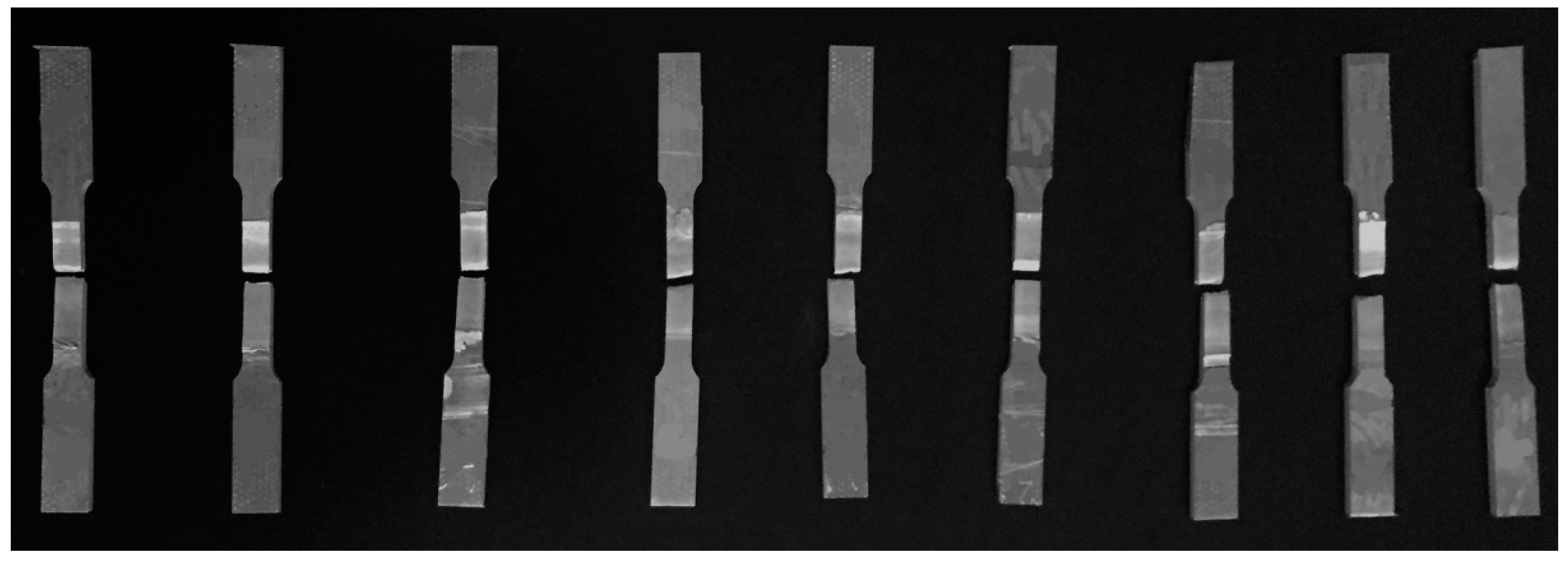
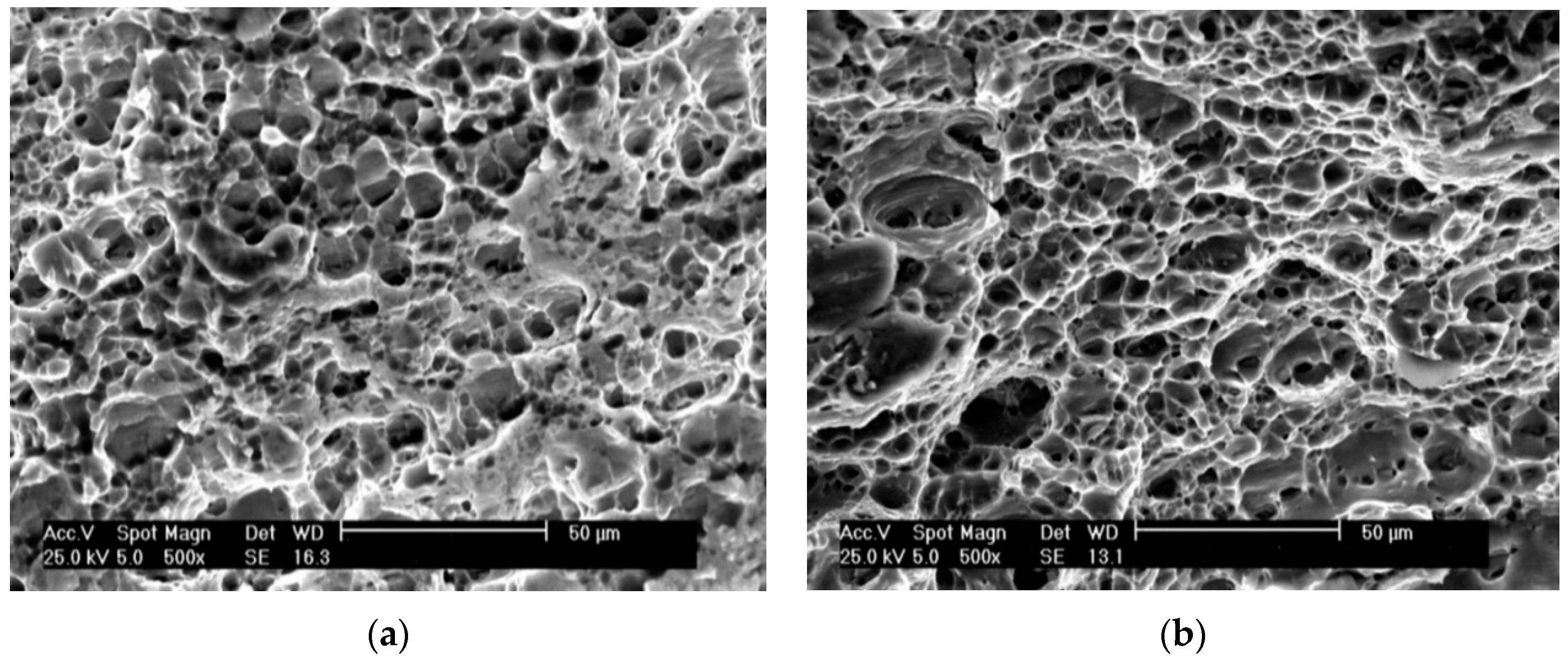
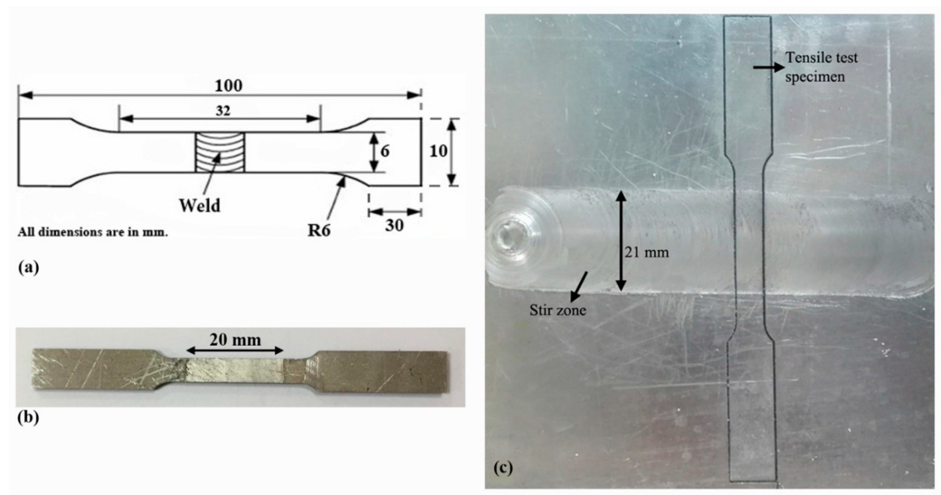
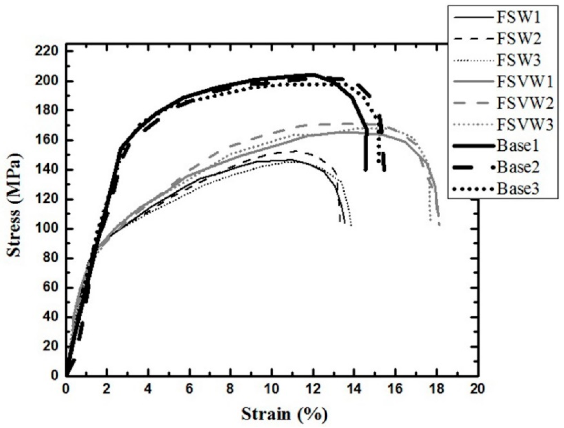
3.2. Mechanical Properties

As the method used to obtain the tensile test specimens can affect the mechanical properties, all test specimens were manufactured utilizing the EDM method. EDM is a proper alternative to milling in tensile specimen manufacturing. It meets the geometric-dimensional requirements, does not affect the ductility of the edge, and does not change the mechanical properties significantly [31]. Tensile test specimens after uniaxial tensile testing are shown in Figure 7. It is observed that for all welding conditions the fracture happens in the FSW zone. In this regard, the mechanical properties of zone are significant for a proper weld.
Stress-strain curves of FS- and FSV-welded specimens are shown in Figure 8. It is observed that strength and ductility of the FSV-welded samples are higher than FS welded specimens. This can be related to grain size effect. It was observed in Figure 6 that FSW zone grain size is smaller in FSV-welded specimens than the FS welded parts. According to the Hall and Petch equation (Equation (1)) [32], strength (σ) increases as grain size (d) decreases:
σ = σ i + k d 1 2
As the grain size decreases, the volume fraction of grain boundaries increases and dislocation movement decreases, which leads to an increase in strength [32]. Grain size refinement has been numerated as one of the strengthening mechanisms [33].
The higher ductility of FSV-welded specimens may also be related to grain size effect in the FSW zone. Various studies have been carried out to determine the effect of grain size on ductility. Some findings have shown that ductility increases as grain size decreases [34,35]. It is believed that a high dislocation density allows a higher degree of plastic deformation and, thus, it provides a high ductility. Transmission electron microscopy images showed that the grain boundaries increase the dislocations density through the generation of new dislocations called geometrically necessary dislocations (GNDs) [36,37] and ductility increased as the grain size decreased. Spittle [38] noted that small grains have a higher resistance to crack propagation due to strain distribution between a greater number of grain boundaries. Ductility enhances in AZ31 magnesium alloy due to the transition in the fracture mechanism from intergranular fracture to transgranular fracture as grain size decreases [39]. SEM pictures of fracture surfaces for FS- and FSV-welded specimens are presented in Figure 9. Both samples show fracture surfaces consisted of voids which is a characteristic of a ductile fracture. Void formation, void coalescence, and crack propagation are three steps which result in fracture in ductile materials and more voids in fracture surface of a ductile material indicate in more ductility [40,41]. Based on Figure 9, the voids for the FSV-welded specimen are more than the other specimen. This indicates that the former specimen has strained more than the latter one before fracture. This agrees well with tensile test results presented in Figure 8.

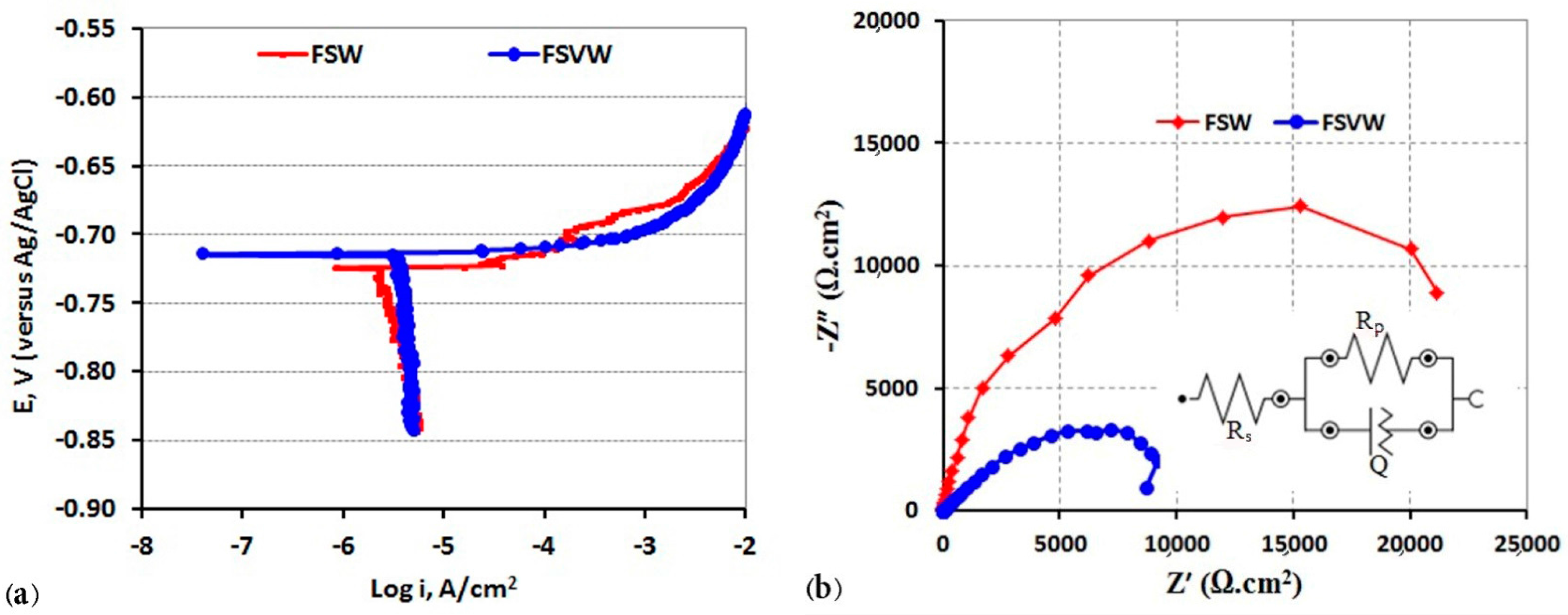
3.3. Corrosion Resistance

The polarization and Nyquist diagrams of two FSW and FSVW samples are illustrated in Figure 10. Considering the polarization curves in Figure 10a and using the Tafel extrapolation method, corrosion rates of about 2.7 µA/cm2 and 5.3 µA/cm2 were obtained for FSW and FSVW samples, respectively. This indicated the better corrosion resistance of FSW samples as compared with FSVW. The larger Nyquist semicircle for the FSW sample in Figure 10b confirms the lower corrosion rate of this sample. According to the Stern-Geary equation (Equation (2)), the corrosion current density and, therefore, the corrosion rate is inversely related to the polarization resistance:
i corr   =   β a β c 2.3   R p ( β a   +   β c )
In Equation (2), i corr is the corrosion current density, R p is the polarization resistance of the electrode, and β a and β c are the anodic and cathodic Tafel slopes, respectively. A simple equivalent circuit shown in Figure 6b was used to calculate the polarization resistance of the samples. Rs, Rp, and Q represent the solution resistance, polarization resistance and constant phase element, respectively. Values of 28,000 Ω·cm2 and 13,500 Ω·cm2 were obtained for the polarization resistance of FSW and FSVW samples, respectively. Therefore, considering the EIS and polarization results it could be concluded that the vibration process resulted in an increase of about 100% in the corrosion rate of the welded samples.
The higher corrosion rate of FSVW samples could be attributed to higher volume fraction of grain boundaries in comparison with FSW samples and this is related to grain size refinement (Figure 6). Lower grain size establishes more grain boundaries. Grain boundaries have high irregularity and energy, which leads to a higher corrosion rate [42]. Increasing the susceptibility to corrosion by decreasing the grain size of the weld regions was also reported by Gharavi et al. [43]. They studied the corrosion behavior of AA6061-T6 aluminum alloy produced by FSW using cyclic polarization and electrochemical impedance spectroscopy tests. Their results indicated that the welding process had a major effect on the corrosion resistance due to dissolution of intermetallic particles that increased the galvanic corrosion couples. They also found that by decreasing the grain size in the weld regions, the corrosion rate increased.
Crack growth rate increased with vibrations during FSVW. Vibration results in more straining and work hardening in the FSW zone and, therefore, grain size decreases and the corrosion rate increases [44].

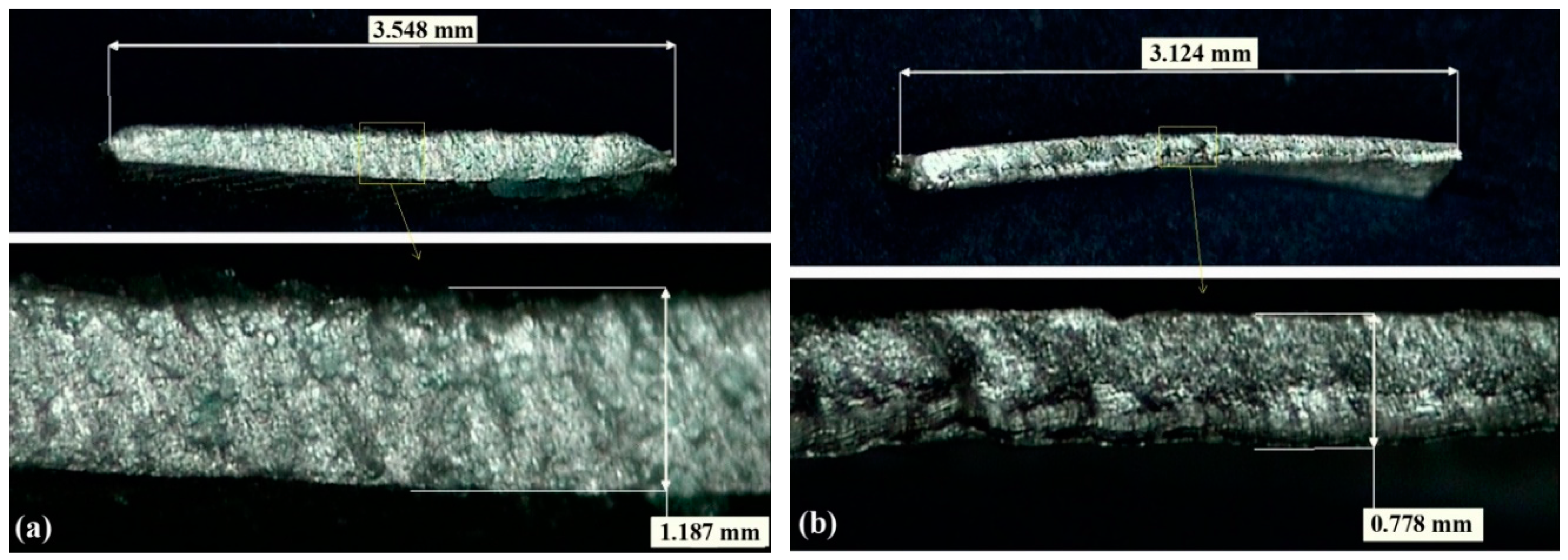
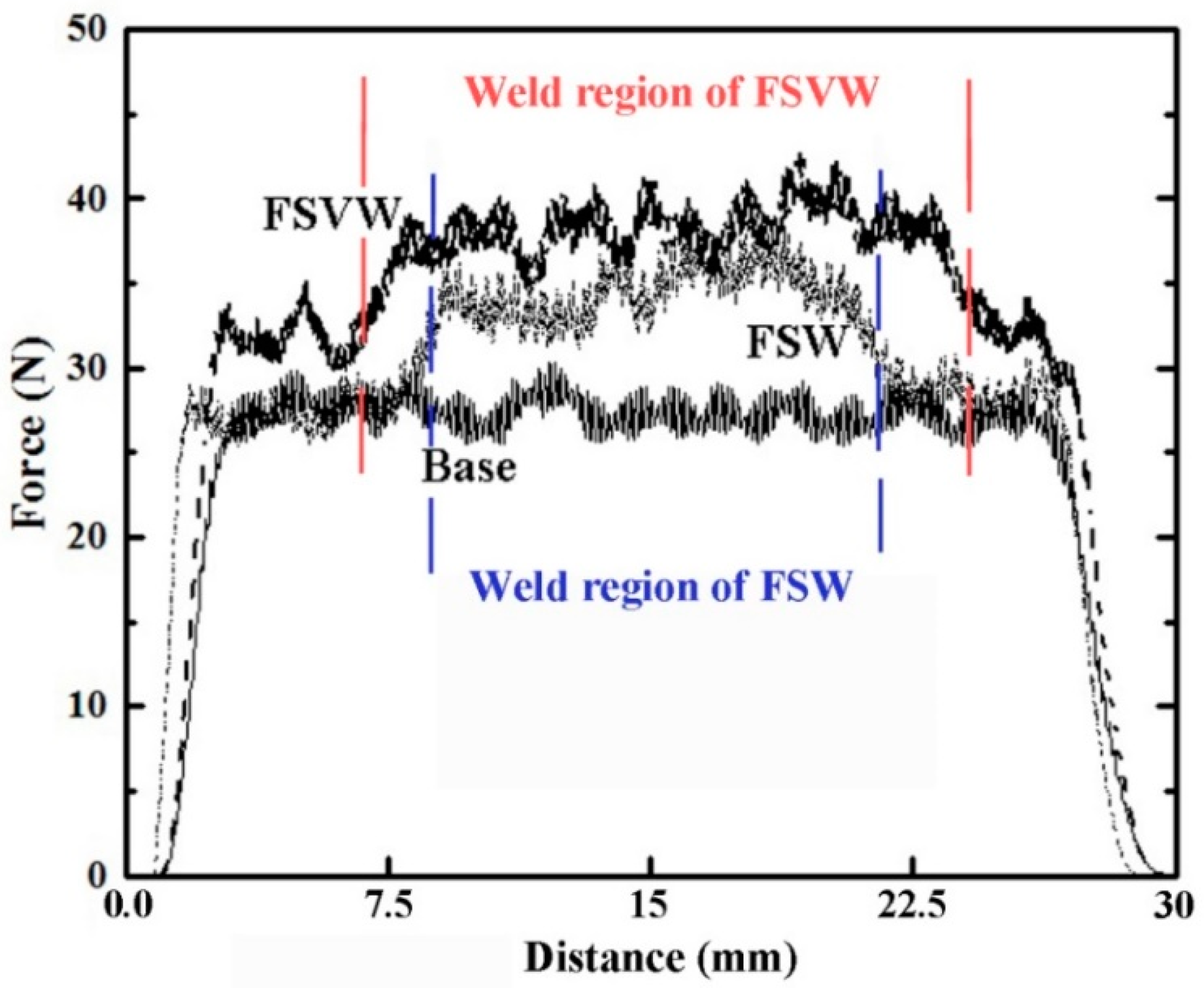
3.4. Machining Characteristics

Cutting force measurements along the cutting path for base material, and FS- and FSV-welded specimens are shown in Figure 11. It is observed that the cutting force for base zones of three samples are about the same, but the force increases in the welded region. It is also observed that the cutting force for welded region of FSV-welded samples is higher than the FS welded samples. These observations can be related to grain size changes during the welding process [45,46].
It was observed (Figure 6) that grain size decreased in the FSW zone because of dynamic recrystallization during the FSW process. Additionally, the presence of vibration during the FSVW process decreased the grain size of the zone. Grain boundaries act as barriers to movement of dislocations and, correspondingly, the greater volume fraction of grain boundaries results in a greater strength of the material [32]. The grain size of FSV-welded is smaller than the FS welded specimen, therefore, higher cutting force was observed during machining.
Chip cross-sections of the cutting process for the welded region of FSV and FS welded specimens are presented in Figure 12. It is observed that the chip length for the FSV-welded specimen is shorter than that for the FS welded specimen and with greater deformation. These observations can be related to higher ductility of material in the zone of the FSV-welded specimens to FS welded specimens (Figure 8). Higher ductility, due to grain refinement, results in more straining of material prior to fracture [47]. As the zone grain size of FSV-welded specimens is lower than the FS welded specimens, its ductility is higher and, correspondingly, the chip is deformed and strained more before removal.

4. Conclusions

In the current research, FSVW as a modified version of FSW is presented. In this process, the joining workpieces were vibrated normal to the weld line during FSW. Al5052 alloy specimens were joined using FSW and FSVW processes and the microstructure, mechanical properties, corrosion resistance, and machining characteristics of both FSW zones were all compared. It is observed that the presence of vibration decreases the grain size in the FSW zone. It is also concluded that:
Strength and ductility of FSV-welded specimens are higher than FS welded specimens.
The corrosion resistance of FSV-welded specimens is lower than FS welded specimens.
The machining force for FSV-welded specimens is higher than that for FS welded specimens.
Chip length of FSV-welded specimens is lower than that relating to FS welded specimens and chips are deformed more after removal.
Further work to monitor temperature variation during both FSW and FSVW processes for different combination of process parameters as well as an investigation into the effect of presence of vibration during FSW on fatigue behavior, residual stress development and microhardness is recommended.

Author Contributions

Mahmoud Abbasi and Morteza Abedini conceived and designed the experiments; Sajad Fouladi and Amir H. Ghasemi performed the experiments; Amir Mahyar Khorasani and Ian Gibson analyzed the data; Mahmoud Abbasi, Morteza Abedini, Amir Mahyar Khorasani and Ian Gibson wrote the paper.

Conflicts of Interest

The authors declare no conflict of interest.

References

  1. Besharati-Givi, M.-K.; Asadi, P. Advances in Friction-Stir Welding and Processing; Elsevier: Amsterdam, The Netherlands, 2014. [Google Scholar]
  2. Abbasi, M.; Abdollahzadeh, A.; Bagheri, B.; Omidvar, H. The effect of SiC particle addition during FSW on microstructure and mechanical properties of AZ31 magnesium alloy. J. Mater. Eng. Perform. 2015, 24, 5037–5045. [Google Scholar] [CrossRef]
  3. Çam, G. Friction stir welded structural materials: Beyond Al-alloys. Int. Mater. Rev. 2011, 56, 1–48. [Google Scholar] [CrossRef]
  4. Keivani, R.; Bagheri, B.; Sharifi, F.; Ketabchi, M.; Abbasi, M. Effects of pin angle and preheating on temperature distribution during friction stir welding operation. Trans. Nonferr. Met. Soc. China 2013, 23, 2708–2713. [Google Scholar] [CrossRef]
  5. Çam, G.; Mistikoglu, S. Recent developments in friction stir welding of Al-alloys. J. Mater. Eng. Perform. 2014, 23, 1936–1953. [Google Scholar] [CrossRef]
  6. Abbasi, M.; Bagheri, B.; Keivani, R. Thermal analysis of friction stir welding process and investigation into affective parameters using simulation. J. Mech. Sci. Technol. 2015, 29, 861–866. [Google Scholar] [CrossRef]
  7. Mishra, R.S.; Ma, Z. Friction stir welding and processing. Mater. Sci. Eng. R Rep. 2005, 50, 1–78. [Google Scholar] [CrossRef]
  8. Lienert, T.; Mishra, R.; Mahoney, M. Friction Stir Welding and Processing; ASM International: Materials Park, OH, USA, 2007; pp. 123–154. [Google Scholar]
  9. Watanabe, T.; Takayama, H.; Yanagisawa, A. Joining of aluminum alloy to steel by friction stir welding. J. Mater. Process. Technol. 2006, 178, 342–349. [Google Scholar] [CrossRef]
  10. Kalaki, A.; Ketabchi, M.; Abbasi, M. Thixo-joining of D2 and M2 tool steels: Analysis of microstructure and mechanical properties. Int. J. Mater. Res. 2014, 105, 764–769. [Google Scholar] [CrossRef]
  11. Urbikain, G.; Perez, J.M.; López de Lacalle, L.N.; Andueza, A. Combination of friction drilling and form tapping processes on dissimilar materials for making nutless joints. Proc. Inst. Mech. Eng. Part B J. Eng. Manuf. 2016. [Google Scholar] [CrossRef]
  12. Elanchezhian, C.; Ramnath, B.V.; Venkatesan, P.; Sathish, S.; Vignesh, T.; Siddharth, R.; Vinay, B.; Gopinath, K. Parameter optimization of friction stir welding of AA8011-6062 using mathematical method. Procedia Eng. 2014, 97, 775–782. [Google Scholar] [CrossRef]
  13. Jafari, M.; Abbasi, M.; Poursina, D.; Gheysarian, A.; Bagheri, B. Microstructures and mechanical properties of friction stir welded dissimilar steel-copper joints. J. Mech. Sci. Technol. 2017, 31, 1135–1142. [Google Scholar] [CrossRef]
  14. Peel, M.; Steuwer, A.; Preuss, M.; Withers, P. Microstructure, mechanical properties and residual stresses as a function of welding speed in aluminium AA5083 friction stir welds. Acta Mater. 2003, 51, 4791–4801. [Google Scholar] [CrossRef]
  15. Yong-Jai, K.; Seong-Beom, S.; Dong-Hwan, P. Friction stir welding of 5052 aluminum alloy plates. Trans. Nonferr. Met. Soc. China 2009, 19, s23–s27. [Google Scholar]
  16. Kumar, P.V.; Reddy, G.M.; Rao, K.S. Microstructure and pitting corrosion of armor grade AA7075 aluminum alloy friction stir weld nugget zone—Effect of post weld heat treatment and addition of boron carbide. Def. Technol. 2015, 11, 166–173. [Google Scholar] [CrossRef]
  17. Maggiolino, S.; Schmid, C. Corrosion resistance in FSW and in MIG welding techniques of AA6XXX. J. Mater. Process. Technol. 2008, 197, 237–240. [Google Scholar] [CrossRef]
  18. Serio, L.; Palumbo, D.; Galietti, U.; De Filippis, L.; Ludovico, A. Monitoring of the friction stir welding process by means of thermography. Nondestruct. Test. Eval. 2016, 31, 371–383. [Google Scholar] [CrossRef]
  19. Serio, L.M.; Palumbo, D.; De Filippis, L.A.C.; Galietti, U.; Ludovico, A.D. Effect of friction stir process parameters on the mechanical and thermal behavior of 5754-H111 aluminum plates. Materials 2016, 9, 122. [Google Scholar] [CrossRef] [PubMed]
  20. Kim, S.; Lee, C.G.; Kim, S.-J. Fatigue crack propagation behavior of friction stir welded 5083-H32 and 6061-T651 aluminum alloys. Mater. Sci. Eng. A 2008, 478, 56–64. [Google Scholar] [CrossRef]
  21. D’Urso, G.; Giardini, C.; Lorenzi, S.; Pastore, T. Fatigue crack growth in the welding nugget of FSW joints of a 6060 aluminum alloy. J. Mater. Process. Technol. 2014, 214, 2075–2084. [Google Scholar] [CrossRef]
  22. Casalino, G.; Campanelli, S.L.; Contuzzi, N.; Angelastro, A.; Ludovico, A.D. Laser-assisted friction stir welding of aluminum alloy lap joints: Microstructural and microhardness characterizations. In Proceedings of the SPIE LASE—International Society for Optics and Photonics, San Francisco, CA, USA, 20 February 2014. [Google Scholar]
  23. Amini, S.; Amiri, M. Study of ultrasonic vibrations’ effect on friction stir welding. Int. J. Adv. Manuf. Technol. 2014, 73, 127–135. [Google Scholar] [CrossRef]
  24. Liu, X.; Lan, S.; Ni, J. Electrically assisted friction stir welding for joining Al 6061 to TRIP 780 steel. J. Mater. Process. Technol. 2015, 219, 112–123. [Google Scholar] [CrossRef]
  25. ASTM E3-11, Standard Guide for Preparation of Metallographic Specimens; ASTM International: West Conshohocken, PA, USA, 2011. [CrossRef]
  26. Kaibyshev, R.; Shipilova, K.; Musin, F.; Motohashi, Y. Continuous dynamic recrystallization in an Al–Li–Mg–Sc alloy during equal-channel angular extrusion. Mater. Sci. Eng. A 2005, 396, 341–351. [Google Scholar] [CrossRef]
  27. Rahmi, M.; Abbasi, M. Friction stir vibration welding process: Modified version of friction stir welding process. Int. J. Adv. Manuf. Technol. 2016, 90, 1–11. [Google Scholar] [CrossRef]
  28. Barooni, O.; Abbasi, M.; Givi, M.; Bagheri, B. New method to improve the microstructure and mechanical properties of joint obtained using FSW. Int. J. Adv. Manuf. Technol. 2017, 1–8. [Google Scholar] [CrossRef]
  29. Hull, D.; Bacon, D.J. Introduction to Dislocations; Elsevier: Amsterdam, The Netherlands, 2011; Volume 37. [Google Scholar]
  30. Fouladi, S.; Abbasi, M. The effect of friction stir vibration welding process on characteristics of SiO2 incorporated joint. J. Mater. Process. Technol. 2017, 243, 23–30. [Google Scholar] [CrossRef]
  31. Krahmer, D.M.; Polvorosa, R.; de Lacalle, L.L.; Alonso-Pinillos, U.; Abate, G.; Riu, F. Alternatives for specimen manufacturing in tensile testing of steel plates. Exp. Tech. 2016, 40, 1555–1565. [Google Scholar] [CrossRef]
  32. Dieter, G. Mechanical Metallurgy, 1988, SI Metric Edition; McGraw-Hill: New York, NY, USA, 2005; ISBN 0-07-100406-8. [Google Scholar]
  33. Callister, W.D.; Rethwisch, D.G. Materials Science and Engineering; John Wiley & Sons: New York, NY, USA, 2011. [Google Scholar]
  34. Naderi, M.; Abbasi, M.; Saeed-Akbari, A. Enhanced mechanical properties of a hot-stamped advanced high-strength steel via tempering treatment. Metall. Mater. Trans. A 2013, 44, 1852–1861. [Google Scholar] [CrossRef]
  35. Ma, Z.; Pilchak, A.; Juhas, M.; Williams, J. Microstructural refinement and property enhancement of cast light alloys via friction stir processing. Scr. Mater. 2008, 58, 361–366. [Google Scholar] [CrossRef]
  36. Schempp, P.; Cross, C.; Häcker, R.; Pittner, A.; Rethmeier, M. Influence of grain size on mechanical properties of aluminium GTA weld metal. Weld. World 2013, 57, 293–304. [Google Scholar] [CrossRef]
  37. Hansen, N. The effect of grain size and strain on the tensile flow stress of aluminium at room temperature. Acta Metall. 1977, 25, 863–869. [Google Scholar] [CrossRef]
  38. Spittle, J.; Cushway, A. Influences of superheat and grain structure on hot-tearing susceptibilities of AI–Cu alloy castings. Met. Technol. 1983, 10, 6–13. [Google Scholar] [CrossRef]
  39. Estrin, Y.Z.; Zabrodin, P.; Braude, I.; Grigorova, T.; Isaev, N.; Pustovalov, V.; Fomenko, V.; Shumilin, S. Low-temperature plastic deformation of AZ31 magnesium alloy with different microstructures. Low Temp. Phys. 2010, 36, 1100–1106. [Google Scholar] [CrossRef]
  40. Ramazani, A.; Abbasi, M.; Prahl, U.; Bleck, W. Failure analysis of DP600 steel during the cross-die test. Comput. Mater. Sci. 2012, 64, 101–105. [Google Scholar] [CrossRef]
  41. Münstermann, S.; Uthaisangsuk, V.; Prahl, U.; Bleck, W. Experimental and numerical failure criteria for sheet metal forming. Steel Res. Int. 2007, 78, 762–770. [Google Scholar] [CrossRef]
  42. Davis, J.R. Corrosion of Weldments; ASM International: Geauga County, OH, USA, 2006. [Google Scholar]
  43. Gharavi, F.; Matori, K.A.; Yunus, R.; Othman, N.K.; Fadaeifard, F. Corrosion behavior of Al6061 alloy weldment produced by friction stir welding process. J. Mater. Res. Technol. 2015, 4, 314–322. [Google Scholar] [CrossRef]
  44. Masuoka, T.; Mayuzumi, M.; Tani, J.-I.; Arai, T. Effect of work hardening on stress corrosion cracking propagation in SUS316L stainless steel. Zair. Kankyo 2007, 56, 93–98. [Google Scholar] [CrossRef]
  45. Zhao, Z.L.; Ai, C.H.; Liu, L. The effect of grain size on cutting force in end milling of inconel 718C. In Materials Science Forum; Trans Tech Publications: Zürich, Switzerland, 2010; pp. 484–487. [Google Scholar]
  46. Komatsu, T.; Yoshino, T.; Matsumura, T.; Torizuka, S. Effect of crystal grain size in stainless steel on cutting process in micromilling. Procedia CIRP 2012, 1, 150–155. [Google Scholar] [CrossRef]
  47. Del Valle, J.; Carreño, F.; Ruano, O.A. Influence of texture and grain size on work hardening and ductility in magnesium-based alloys processed by ECAP and rolling. Acta Mater. 2006, 54, 4247–4259. [Google Scholar] [CrossRef]
Figure 1. The machine designed and manufactured for FSVW process.
Metals 07 00421 g001
Figure 2. Schematic design and geometry of the tool used for FSW and FSVW processes.
Metals 07 00421 g002
Figure 3. (a) Schematic design of the tensile test specimen, and (b) tensile test specimen for FS- and (c) FSV-welded specimens.
Metals 07 00421 g003
Figure 4. Schematic design of cutting process for welded specimens.
Metals 07 00421 g004
Figure 5. Weld region microstructures of (a) FS- and (b) FSV-welded specimens.
Metals 07 00421 g005
Figure 6. Microstructures of (a) the FSW zone of the FS welded specimen, (b) the FSW zone of thre FSV-welded specimen, and (c) the base material.
Metals 07 00421 g006
Figure 7. Tensile test specimens after uniaxial tensile testing.
Metals 07 00421 g007
Figure 8. Stress-strain curves of FS- and FSV-welded specimens, as well as the base material.
Metals 07 00421 g008
Figure 9. SEM pictures from fracture surfaces of (a) FS- and (b) FSV-welded specimens.
Metals 07 00421 g009
Figure 10. Polarization (a) and Nyquist (b) curves of FSW and FSVW samples.
Metals 07 00421 g010
Figure 11. Force values measured during cutting process for different samples, and FS- and FSV-welded samples, as well as the base material.
Metals 07 00421 g011
Figure 12. Presentation of chip cross section for different samples, (a) FSW zone of FS welded sample, and (b) FSW zone of FSV-welded sample.
Metals 07 00421 g012
Table 1. Welding conditions for applied experiments.
ExperimentVibrationRotation Speed (rpm)Transverse Speed (mm/min)
FSW120030
FSVW+120030
Table 2. Specifications of end mill tool.
ItemsSpecifications
Tool materialHSS
Number of Flutes4
Helical angle (°)35
Diameter (mm)10
Rake angle (°)7
Gash angle (°)40
Dish angle (°)4
Radial primary clearance angle (°)8
Radial secondary clearance angle (°)15
Table 3. Cutting conditions applied during machining.
ItemsSpecifications
Spindle speed (rpm)360
Feed per tooth (mm/edge)0.033
Feed rate (mm/min)45
Depth of cut (mm)1
Tool and work engagement (mm)3
Cutting length (mm)30 ± 2

