Article

Designing of Synergistic Waste Mixtures for Multiphase Reactive Smelting

by
Vaso Manojlović
1,*,
Željko Kamberović
2,
Miroslav Sokić
1,*,
Milorad Gavrilovski
3 and
Marija Korać
2
1
Institute for Technology of Nuclear and Other Mineral Raw Materials, 86 Franchet d’ Esperey St., Belgrade 11000, Serbia
2
Faculty of Technology and Metallurgy, University of Belgrade, 4 Carnegie St., Belgrade 11000, Serbia
3
The Innovation Center at Faculty of Technology and Metallurgy, University of Belgrade, 4 Carnegie St., Belgrade 11000, Serbia
*
Authors to whom correspondence should be addressed.
Metals 2016, 6(6), 138; https://doi.org/10.3390/met6060138
Submission received: 29 March 2016 / Revised: 20 May 2016 / Accepted: 24 May 2016 / Published: 8 June 2016
(This article belongs to the Special Issue Recycling of Metals)

Abstract

:
Electric arc furnace (EAF) dust, together with a mill scale and coke were smelted in a laboratory electric arc furnace. These metallurgical wastes consist of a many different phases and elements, making the reaction process complex. Thermo-chemical analysis of the reactions in metal, slag, and gas phases was done, and used for modeling of the mixture composition and energy consumption required for smelting. Modelling was performed with the software named RikiAlC. The crude ZnO, slag, and metal phase were analyzed using the atomic absorption spectrometry (AAS), the optical emission spectrometry with inductively coupled plasma (ICP-OES), the X-ray diffraction (XRD), the scanning electron microscopy (SEM) equipped with energy dispersive spectrometry (EDS), and reflected and transmitted light microscopy. Also, in order to follow the behavior of this process the exhausted gases were monitored. The synergetic effects of the designed mixture may be recognized in minimizing energy consumption for the smelting process, improving the product yield efficiency, and reducing the negative environmental effects.

Graphical Abstract

1. Introduction

In a secondary steelmaking process 15–20 kg of the EAF dust is generated per ton of produced steel [1,2]. The EAF dust consists usually of zinc, iron, lead, cadmium and halogens (chlorine and fluorine), and in some cases nickel and chromium [3]. Both the pyro and hydro-metallurgical processes have technical and technological limitations in the processing of EAF dust. The pyrometallurgical methods for treatment of the EAF dust are preferred, because of the difficulty in leaching of the Franklinite (ZnFe2O4) [3,4,5]. Carbon reduces the leaching residue into iron and zinc at high temperatures, so the combination of these two methods can be applied [6]. Mill scale is generated in steelmaking industry; it mainly consists of iron oxides and relatively small amounts of the sulfur, phosphorus, and alkalis [7].
The chemical energy provided by an optimized carbon/oxygen ratio can replace the part of electrical energy for recovery of iron and zinc in an EAF dust. The semi-empirical thermo-chemical model was developed and verified to determine the carbon/oxygen ratio as well as to calculate overall needed or released process energy [8]. This model can be solved with the help of developed discrete non-commercial software RikiAlC [8,9].
The final products from the reduction process of the prepared mixture are the iron, the slag, and the crude ZnO dust. In addition, carbon monoxide, as by-product, can serve as energy source or for treating the pellets before smelting. Calculation of the mixture composition was performed to achieve good energy efficiency and higher yields of the Fe, ZnO, Pb, and Cd from the input materials. The mixture composition was designed taking into account:
  • the optimal amount of reducing agent,
  • the energy of reactions,
  • the final composition of dust and slag.

2. Experimental Section
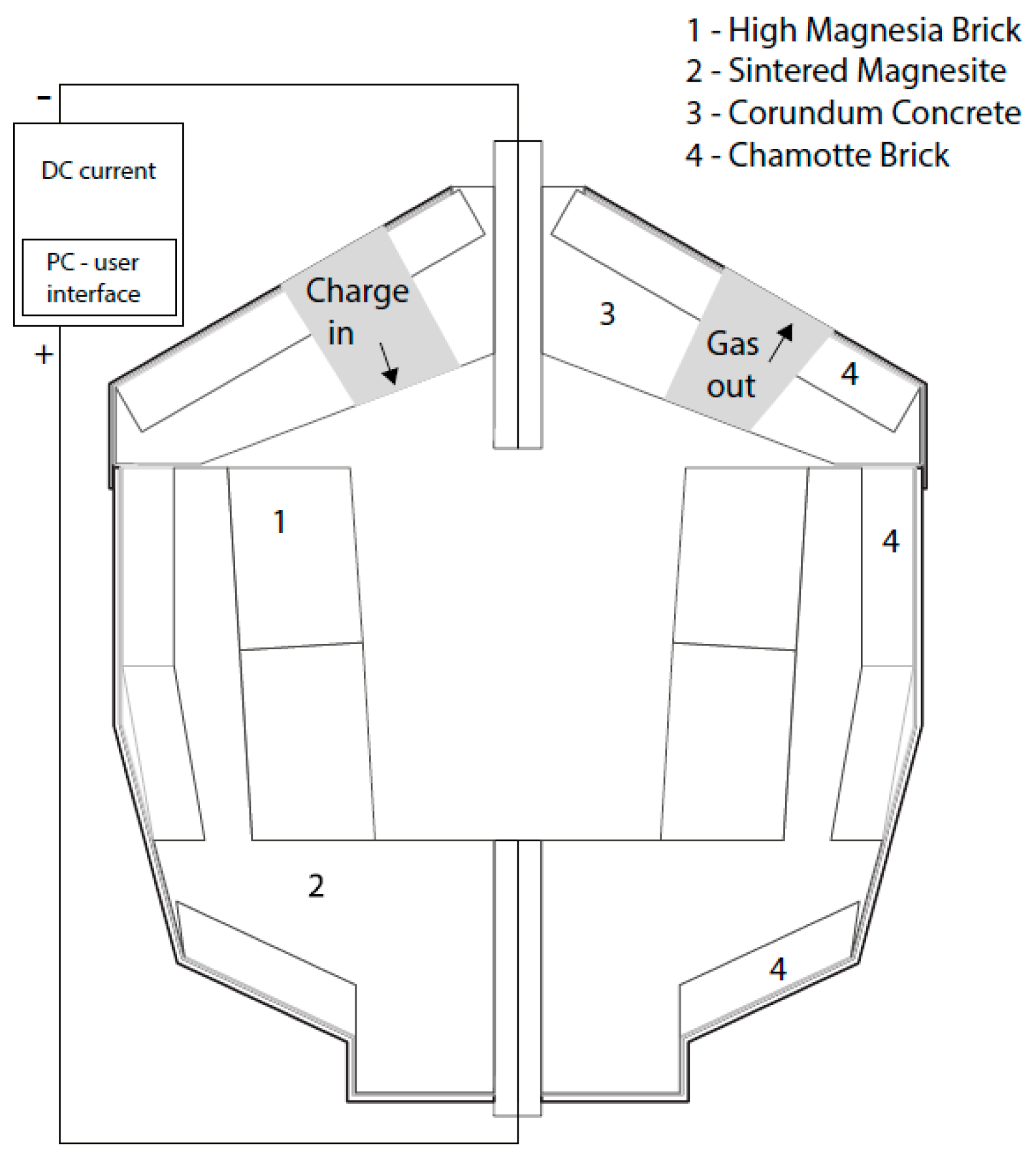
2.1. Set-up

The EAF dust, mill scale, coke, and lime were agglomerated on the semi-industrial pelletizing disk at an angle of 45° and with rotation of 15 rpm. The mixture composition was previously modelled based on thermodynamic calculations, using RikiAlC software (Version 1.0, 2015, The Innovation Center at Faculty of Technology and Metallurgy, Belgrade, Serbia) [8,9]. The pellet size was in a range between 6 and 10 mm. The green pellets were dried at 353 K for 24 h, with 7.8% of weight loss, which is attributed to the moisture content. The weight of dried pellets, prepared for the melting process in the furnace was 85 kg.
The laboratory scale DC electric arc furnace (EL-100, Eling, Loznica, Serbia) with a maximal power of 100 kW and working capacity of 0.4 m3 was used for the melting of prepared pellets (Figure 1).
Pellets were charged in the furnace, manually, at several time steps until depleting the prepared amount of pellets. The operating power of furnace was 45 kW and a time step was between 10 and 15 min. At the beginning of the melting process 15 kg of starting slag was added to ensure the liquid bath for melting the pellets. The composition of the starting slag is given in Table 1.
After leaving the furnace, the hot gas was mixed with air and cooled with a water cooling system. Dust was collected in the bag filter; immediately after leaving the bag filter, the gas emission was measured.

2.2. Materials and Methods

Input materials mixture consists of the EAF dust, the mill scale, the coke, and the lime. The chemical compositions of the input materials and products were determined by AAS (Perkin-Elmer model AANALYST 300, Perkin-Elmer, Norwalk, CT, USA) and by ICP-OES (Thermo Scientific iCAP Qc, Thermo Scientific, Waltham, MA, USA). Chemical composition of the EAF dust is given in Table 2.
Phase compositions of the EAF dust, the mill scale, the slag and the zinc-oxide dust were determined using XRD (PHILIPS PW-1710, Philips, Eindhoven, The Netherland) with a graphite monochromator, using Cu-Kα radiation. This EAF dust was generated in the melting process of the steel scrap; the selected smelting plant was situated at Sirmium Steel Ltd., Sremska Mitrovica, Serbia.
Some of the relevant phases detected with XRD of the EAF dust were: zincite (ZnO), spinels ((Fe, Zn) Fe2O4), garnets, pyroxenes, laurionite (PbCl(OH)), wurtzite (Zn0.9Fe2+0.1S) and sylvite (KCl) (Figure 2).
A spinel like phase determined franklinite (ZnFe2O4), magnetite (Fe3O4), and hausmannite (Mn3O4), marked as S-Spinel on Figure 1. Further on, the Ca and Mn can replace the Fe ion in the magnetite spinel phase to form Ca0.15Fe2.85O4, and MnFe2O4 [10,11]. A pyroxene phase family is presented with hedenbergite (CaFeSi2O6), which forms a continuous series of solid solutions with diopside (CaMgSi2O6). A garnet phase family, based on chemical analysis, may contain pyrope (Mg3Al2(SiO4)3), almandine (Fe3Al2(SiO4)3), andradite (Ca3Fe2(SiO4)3) and similar. Although halite (NaCl), with its low composition was not detected in the XRD spectra, some researchers have reported this phase in the EAF dust [4,10,12,13].
The mill scale was, also, generated in Metalfer Steel Mill Ltd., Sremska Mitrovica, Serbia. The chemical composition is given in Table 3. The iron in the mill scale was bound as magnetite (about 40 wt. %), wustite (57 wt. %), and hematite (3 wt. %).
The lime and the coke compositions are presented in Table 4 and Table 5, respectively.
The EAF dust agglomerate size was approximately 100 μm, with mean particle size in the range from 0.05 to 10 μm [14]. The mean mill scale particle size was 1.32 mm (85%). The mean coke particle size was 1 mm (85%) [14].
A microscopic analysis of crude ZnO dust was done on SEM connected with INCA energy-dispersive X-ray analysis unit EDX (JEOL JSM-5800, JEOL, Tokyo, Japan). Mineralogical microscopic investigation of the slag was performed in reflected and transmitted light, JENAPOL-U microscope (Carl Zeiss, Jena, Germany), using parallel profile method (interval 1 mm). The chemical composition of the metal phase was determined by Spectromaxx arc/spark optical emission spectrometer (SPECTRO Analytical Instruments GmbH, Kleve, Germany).
Temperature of the slag and the molten iron was measured with a Pt/Pt-10 wt. %Rh thermocouple, which was placed at the end of the probe.
Gas emission was measured with Testo 340 flue gas analyzer (Testo INC, Lenzkirch, Germany) on CO, NOx, and SO2, with a temperature of 315 K.

3. Designing Mixture Composition and Energy Consumption

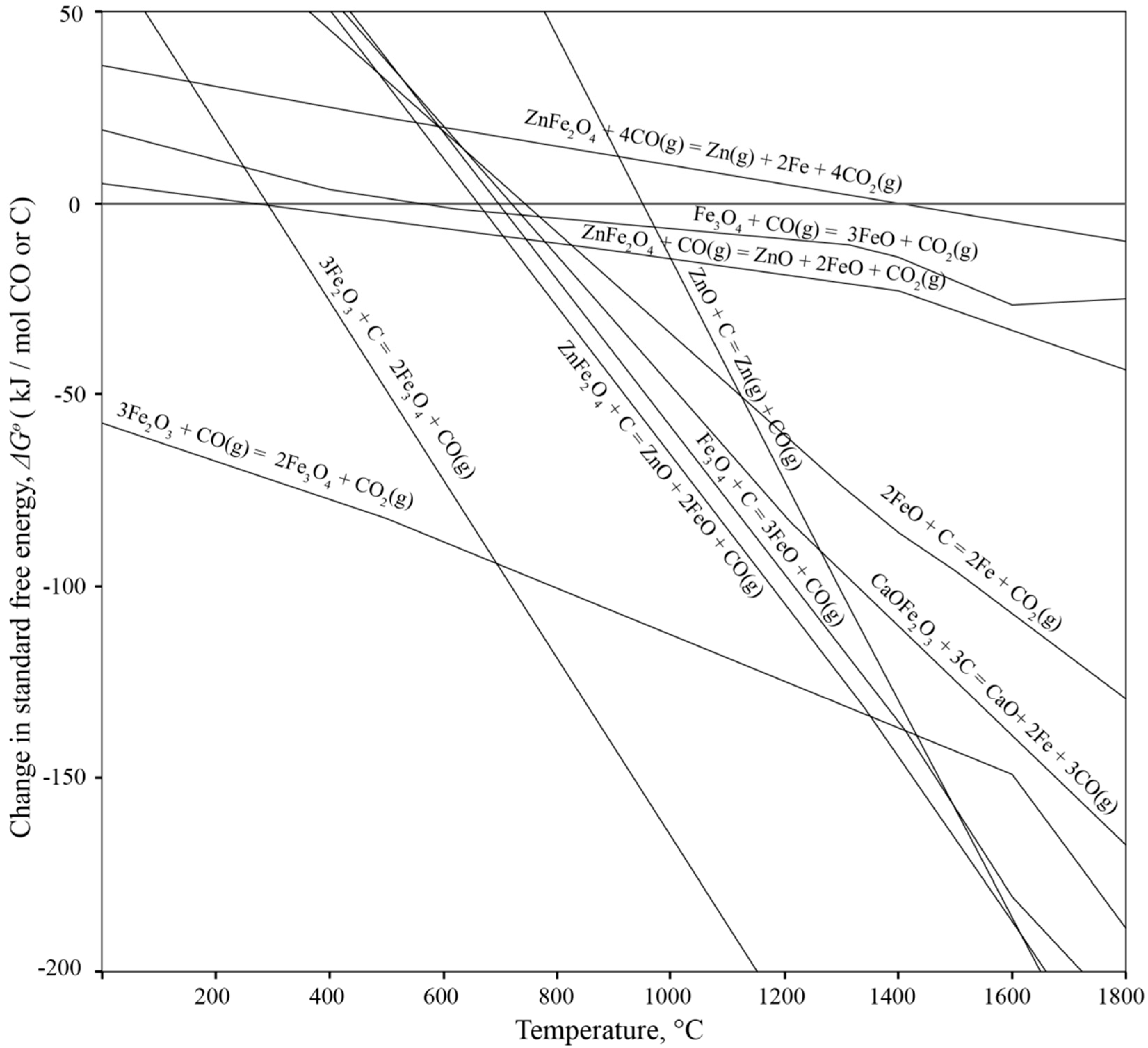
3.1. Thermo-Chemical Considerations

3.1.1. Processes inside the Furnace

When the pellet reaches the process temperature in the range 1673–1873 K, after several minutes, the reduction processes become completed. The gaseous phases, released from the reduction processes, migrate, relatively fast, through the layer of non-reduced pellets. Hence, in electro reductive furnaces, the reduction of ferrous ores with carbon monoxide occurs in the range 10%–15% compared to the reduction with carbon [15,16,17].
At 1873 K the carbon and the carbon monoxide will reduce a majority of the oxides in the mixture; it is shown following the values of Gibbs free energy changes, in Figure 3 [8,9,17].
The reduction of ferrous-oxides are [17,18,19]:
3 Fe 2 O 3 + C = 2 Fe 3 O 4 + CO ( g )   Δ H 298 θ = 127.4 KJ
3 F e 2 O 3 +   C O ( g )   =   2 F e 3 O 4 +   C O 2 ( g )   Δ H 298 θ =   44.9   k J
F e 3 O 4 +   C   =   3 F e O   +   C O ( g )   Δ H 298 θ =   203.0   k J
F e 3 O 4 +   C O ( g )   =   3 F e O   +   C O 2 ( g )   Δ H 298 θ =   30.7   k J
2 F e O   +   C   =   2 F e   +   C O 2 ( g )   Δ H 298 θ =   141.1   k J
F e O   +   C O ( g )   =   F e   +   C O 2 ( g )   Δ H 298 θ =   15.6   k J
These reactions occur below process temperature, at temperature range of 1373–1673 K. The reactions of ferric oxides with carbon (Equations (1), (3) and (5)) are more favorable (in DC electric arc furnace), and they contribute to 85%–90% of overall ferric oxides reduction [17]. The direct reduction with carbon at solid-solid and solid-liquid interface depends on carbon diffusion in the solid phase and/or in the liquid phase. The intermediate phases or spinel of Ca, Mg, and Si-oxides can form layer between ferro-oxides and carbon, creating a barrier for carbon diffusion and reduction processes. A diffusion rate of carbon increases by increasing the temperature and the contact surface between the carbon and the metal-oxides [20]. It is important that the Equation (1) takes place with a higher rate, otherwise the following reactions could occur [21]:
F e 2 O 3 +   C a O   =   C a O F e 2 O 3   Δ H 298 θ =   21.5   k J
F e 2 O 3 +   2 C a O   =   2 C a O F e 2 O 3   Δ H 298 θ   =   40.9   k J
In the slag phase CaO∙Fe2O3 and 2CaO∙Fe2O3 together with Si and Mg can form the spinel structures which inhibit the diffusion of carbon to ferric ions so their reduction to metallic iron is prevented [20,21]. At temperatures higher than 1053 K, the CaO∙Fe2O3 and 2CaO∙Fe2O3 can react with carbon according to the following reactions [21]:
C a O F e 2 O 3 +   3 C   =   C a O   +   2 F e   +   3 C O ( g )   Δ H 298 θ =   512.9   k J
2 C a O F e 2 O 3 +   3 C   =   2 C a O   +   2 F e   +   3 C O ( g )   Δ H 298 θ =   532.3   k J
The intense conditions in DC electric arc furnace and the sufficient amount of carbon favor the Equations (9) and (10) rather than (7) and (8), particularly in the zone of electric arc where the temperatures are high. Therefore, the pellets have to be introduced in the furnace at the zone close to the electric arc.
The reduction of franklinite is very important due to its high amount in the EAF dust. There are two main reactions for franklinite reduction:
Z n F e 2 O 4 +   C   =   Z n O   +   2 F e O   +   C O ( g )   Δ H 298 θ =   183.3   k J
Z n F e 2 O 4 +   C O ( g )   =   Z n O   +   2 F e O   +   C O 2 ( g )   Δ H 298 θ =   11.0   k J
In the DC electric arc furnace, the formed carbon-monoxide quickly passes through the pellets and fills the chamber of the furnace. Hence, the Equation (12) participates to a lesser extent than the Equation (11), although it is kinetically favorable due to the higher rate of mass transfer between solid-gas phases [20].
The franklinite can react with the calcium-oxide according to the exothermic reaction, which has negative value of free energy change at elevated temperature [3]:
Z n F e 2 O 4 +   2 C a O   =   Z n O   +   2 C a O F e 2 O 3   Δ H 298 θ =   35.4   k J
The 2CaO∙Fe2O3 phase can be incorporated into the slag phase and so forms the spinel phase, which is not convenient for recovery of iron. Despite that, at relatively high temperatures, this phase can be decomposed by the Equation (10).
Zincite (ZnO) from the EAF dust is reduced with the carbon and carbon-monoxide, which can be described by equations:
Z n O   +   C   =   Z n ( g )   +   C O ( g )   Δ H 298 θ =   370.4   k J
Z n O   +   C O ( g )   =   Z n ( g )   +   C O 2 ( g )   Δ H 298 θ =   198.0   k J
The carbon will first reduce the less stable oxides, such as ZnO, then ferrous oxides. In the literature data, the influence of the mill scale, hematite, and calcium carbonate on kinetics of zincite reduction was studied [15]. It was shown that calcium carbonate accelerates the reduction of zincite, significantly reducing the activation energy of Equations (14) and (15) [15]. That is not significant in the case of the electric arc furnace, because the carbon is the main reducing agent. The CO2(g) formed from the above reactions react with the carbon at temperatures above 1173 K according to Boudouard equation:
C O 2 ( g )   +   C   =   2 C O ( g )   Δ H 298 θ =   172.4   k J
Considering the above reactions, the atmosphere in the furnace chamber will mainly contain carbon-monoxide with small amount of a carbon-dioxide.

3.1.2. Processes outside of the Furnace Chamber

After leaving the chamber of the furnace, the gas mixes with the air. The zinc in gaseous phase reacts with the carbon-monoxide and carbon-dioxide if the temperature is below 1173 K, and with oxygen when leaving the furnace chamber according to the Equations [8,9]:
Z n ( g ) + C O ( g ) = Z n O + C   Δ H 298 θ = 370.4   k J
Z n ( g ) + C O 2 ( g ) = Z n O + C O ( g )   Δ H 298 θ = 198.0   k J
2 Z n ( g ) + O 2 ( g ) = 2 Z n O   Δ H 298 θ = 961.8   k J
The obtained ZnO is collected in the bag filter in powdered form. The carbon-monoxide will be oxidized to the carbon-dioxide, releasing the heat as it is shown in:
2 C O ( g ) + O 2 ( g ) = 2 C O 2 ( g )   Δ H 298 θ = 565.8   k J
Chlorine in the EAF dust is mainly in the form of sylvite (KCl) and PbCl2 dissociated from laurionite. The sylvite and halite react above 873 K with PbO by equations [13]:
2 KCl + PbO + 2 Si O 2 + Al 2 O 3 = PbCl 2 ( g ) + 2 KAlSi O 4   Δ H 298 θ = 172.2   k J
2 NaCl + PbO + 2 Si O 2 + Al 2 O 3 = PbCl 2 ( g ) + 2 NaAlSi O 4   Δ H 298 θ = 174.4   k J
Therefore, chlorine has a major role in the evaporation mechanism of lead from the mixture. When leaving the furnace, PbCl2 will react with the oxygen and carbon-monoxide, which become more energy favorable by decreasing the temperature, this is presented by equations:
PbCl 2 ( g ) + C O ( g ) + O 2 ( g ) = PbO + Cl 2 ( g ) + C O 2 ( g )   Δ H 298 θ = 326.9   k J
PbO + C O ( g ) + O 2 ( g ) = Pb O 2 + C O 2 ( g )   Δ H 347.7 θ = 347.7   k J
Lee and Song studied the effect of chlorine on Zn, Pb, and Cd evaporation from the EAF dust [12]. They showed that at temperatures higher than 873 K, the evaporation of these elements through chlorides rapidly increases and will finish at 1273 K [12]. Based on the thermodynamic calculations, a diagram of vapor pressure for various components was constructed as shown in Figure 4 [8,9]. Due to the low vapor pressure of FeCl3, a certain amount of the iron can be expected in the crude ZnO dust.
The cadmium will evaporate in a pure metal form rather than in a chloride form, as it can be seen in Figure 4. If the cadmium is in oxide form then its reduction by carbon will occur at 873 K, and then it will evaporate in a metallic form and oxidize when leaving the furnace chamber by reactions [9]:
CdO + C = Cd ( g ) + C O ( g )   Δ H 298 θ = 260.3   k J
Cd = Cd ( g )   Δ H 298 θ = 111.8   k J
2 Cd ( g ) + O 2 ( g ) = 2 CdO   Δ H 298 θ = 741.7   k J
The zinc sulphide from wurtzite will react with the liquid copper at temperatures above 1362 K, because it has the highest affinity toward the sulfur [9]. In addition, lead can form sulfides and evaporate at 1643 K, together with the sulfur dioxide, which originates from the coke and the mill scale [9]. If there is an excess of sulfur in the input materials, the matte phase with Cu and Ni can form [22].

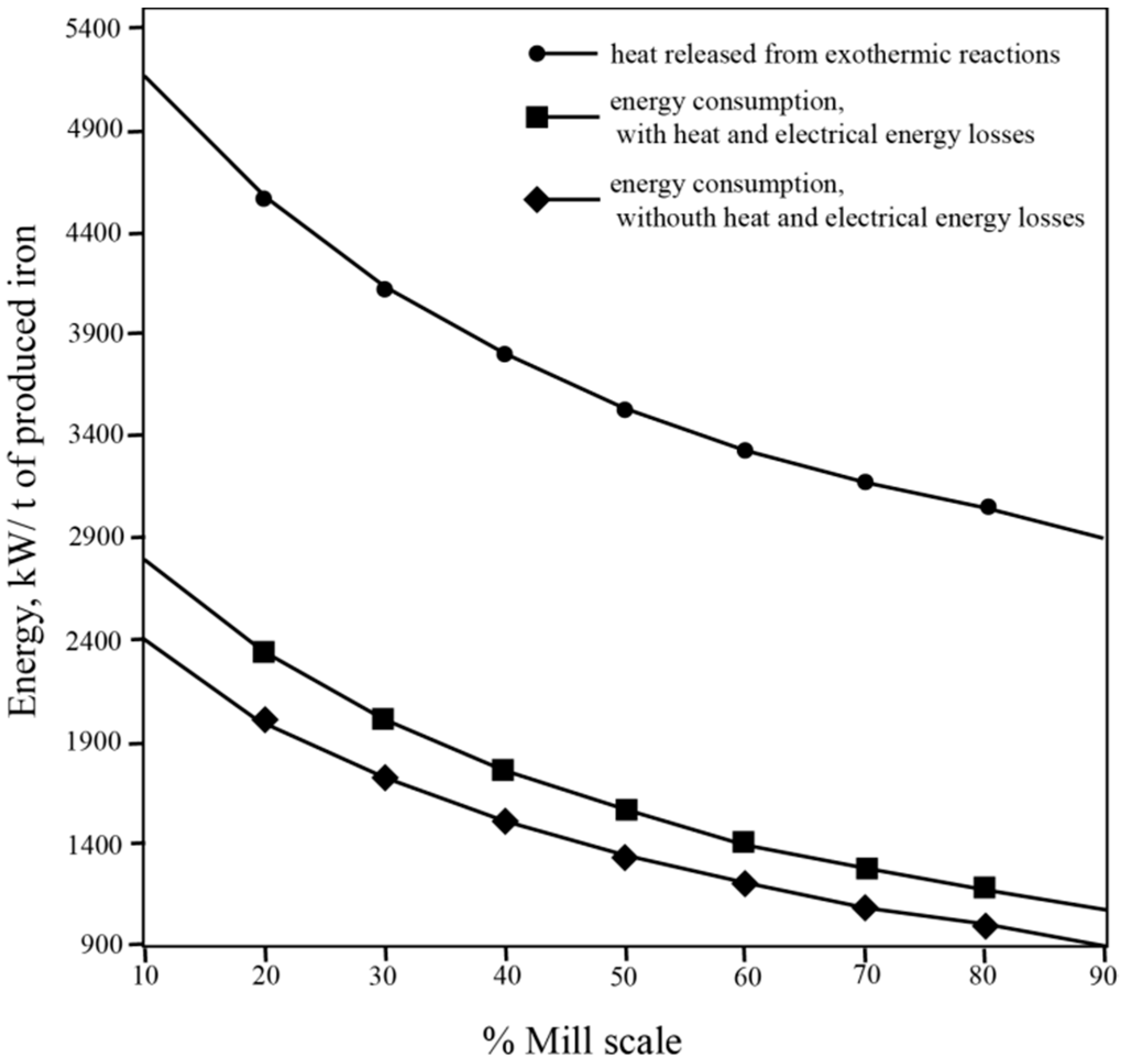
3.2. Mixture Composition and Energy Consumption
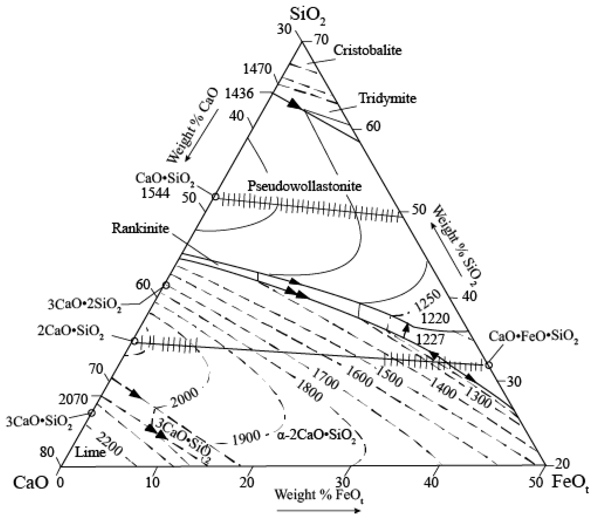
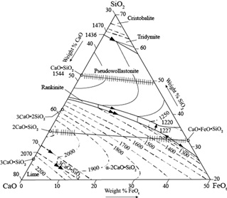
The simulation of the process energy consumption and material balance was realized using RikiAlC software on the mixture of mill scale and EAF dust with the required quantity of coke. The energy consumption was calculated based on the enthalpies of Equations (1)–(27), which are stored in a software database together with chemical compositions and amounts of input materials. Calculations of ∑∆Hi for all reactions were evaluated at 298 K and the maximum temperature was 1873 K. For the selected multicomponent system, the heat needed for analyzed reactions is:
Q = ∑ΔHi
where ∆Hi refers to the heat needed by each reaction that occurs in the system, and can be calculated by:
Δ H i = Δ H th × m p r m p th
where ∆Hth is a change of theoretical enthalpy for each reaction that occur in the system with the products mass of Σ m p th ; the Σ m p r is a real mass of products calculated based on the mass of input materials related to the given reaction. The energy consumption results are given in Figure 5, where different amounts of the mill scale and the EAF dust were analyzed. A higher share of the EAF dust will increase energy consumption for each ton of produced iron. The increase of EAF dust will slow down the rates of all reactions, because dispersed particles in the dust will inhibit contact between reductant and oxides in the mill scale. Further on, the production of the crude zinc oxide will increase. The optimal ratio was chosen as 55% of the mill scale and 45% of the EAF dust, which corresponds to the energy consumption below 1660 kW/t of produced iron, including heat and electrical energy losses. The values of heat and electrical energy losses are 9% and 8%, respectively, which is applicable for electric arc furnaces with a low body and capacity of below 15 MVA [23].
This mixture will consume 11.79% of carbon for reduction of all reducible oxides. That is the stoichiometric amount calculated using the software, based on Gibbs free energies of reactions in Section 3.1 in relation with the input material amounts. The calculated carbon amount was multiply by excess coefficient of 1.2 that takes into account the losses of carbon in real terms. The designed mixture composition for pellet production based on the above simulations is: 37.0% of the EAF dust; 45.1% of the mill scale; 16.2% of the coke (Cfix = 87%); and 1.7% of the lime.
The carbon in the electro-reduction processes serves as reducing agent, while electrical energy as a heat source. That heat is consumed by the endothermic reactions, and for the heating of the ferrous, the slag, and the gas components. The lost part of the heat is lost by radiation and convection, while part of electrical energy is loosed in the furnace electrical circuit. The carbon converts to carbon monoxide, reacting with the oxygen outside of the furnace by reaction (20) and releasing a significant amount of heat (Figure 5). The released heat can be used in a different ways, for example for production of electrical energy, or for reduction of pellets before charging [24,25]. For designed mixture, heat released from exothermic reactions (mainly reaction 20) is 3471 kW/t of produced iron. According to the literature data, this heat can generate power by turbine up to 1673 kW/t of produced iron [24]. Theoretically, all electrical energy consumption can be supplied by this source of energy, so only the coke costs enter into the process economy. Further, the carbon monoxide can reduce and heat pellets before charging, which will replace a part of electrical consumption. These two cases can be combined to achieve optimal conditions to achieve economic efficiency. To analyze these cases, the exergy calculations, probably, may be convenient [24,25]. These calculations are not done here, because the focus is on achieving the synergy of input materials. This synergy is achieved by improving products valorization, minimizing energy consumption for a given input material (as it is shown in Figure 5), and reducing negative environmental effects. In the proposed process, three main products appear: crude zinc oxide, the slag from heavy metals, and iron. The crude zinc oxide could further processed with hydro-metallurgical procedures, to remove Pb and Cd. In addition, the carbon monoxide can be used for reduction of pellets or for energy recovery. Although, in practice, the energy recovery from a high dust-loaded off-gas is quite difficult due to the dust sticking on the heat equipment leading to the heavy dust settlements.

Slag Composition

The slag interacts with the molten metal, the gases, the coke, and the furnace wall, hence the slag composition, its basicity, and viscosity is both complex and important. The basicity index of the slag was determined using the relation [17]:
B = % CaO + % MgO % SiO 2 + % Al 2 O 3
In the slag, according to designed mixture the content of CaO is in the range 39%–48%, content of SiO2 is in the range 30%–38%, content of FeO is 10% and higher, content of MgO is in the range 8%–15%, content of Al2O3 is in the range 5%–8%, and finally, the content of MnO is not greater than 3%.
Figure 6 shows the melting points of this slag system, and they are situated between 1573 and 1773 K [26].
The determined basicity index is set to be higher than 1.2 for two main reasons to avoid the reaction between the furnace wall and the slag, and to provide the optimal viscosity of the slag at the process temperature. This basicity can be achieved by adding a higher amount of lime with 5%–7%. Slag liquid viscosity was estimated using Urbain model by Mills et al. [27,28]. The calculated slag viscosity is 1.19 Poise for temperature of 1873 K and 3.03 Poise for temperature of 1673 K. The designed composition of the slag has to provide a foaming of the slag and the required viscosity in order to achieve optimal refining capabilities, higher metal yield, and lower energy consumption. A higher amount of carbon in the slag layer can enable good foaming, better arc stability, and better electrical efficiency.
The presence of zincite and wustite in the liquid slag can imply formation of the spinels as it was indicated in literature [29], but at temperatures higher than 1673 K the zinc will evaporate according to Equations (11)–(15). The low viscosity of liquid slag will enable good fuming of gaseous zinc through the slag.

4. Discussion

The melting process of the pellets with designed mixture composition lasted 80 min with an operating power of 45 ± 2 kWh, which corresponds to the energy consumption of 1930 ± 40 kWh/t of the produced iron. Comparing this energy consumption with the calculated energy consumption of 1660 kWh/t of produced iron, it is obvious that 270 ± 40 kW will be lost, mainly as heat and electrical energy losses. This difference is expected, and occurred because a laboratory scale furnace was used.
Slag, metal, and dust phases were carefully collected, however certain material losses is inevitable, mainly due to the adhesion of material to the furnace walls. The modeled and experimental material balance is given in Table 6.

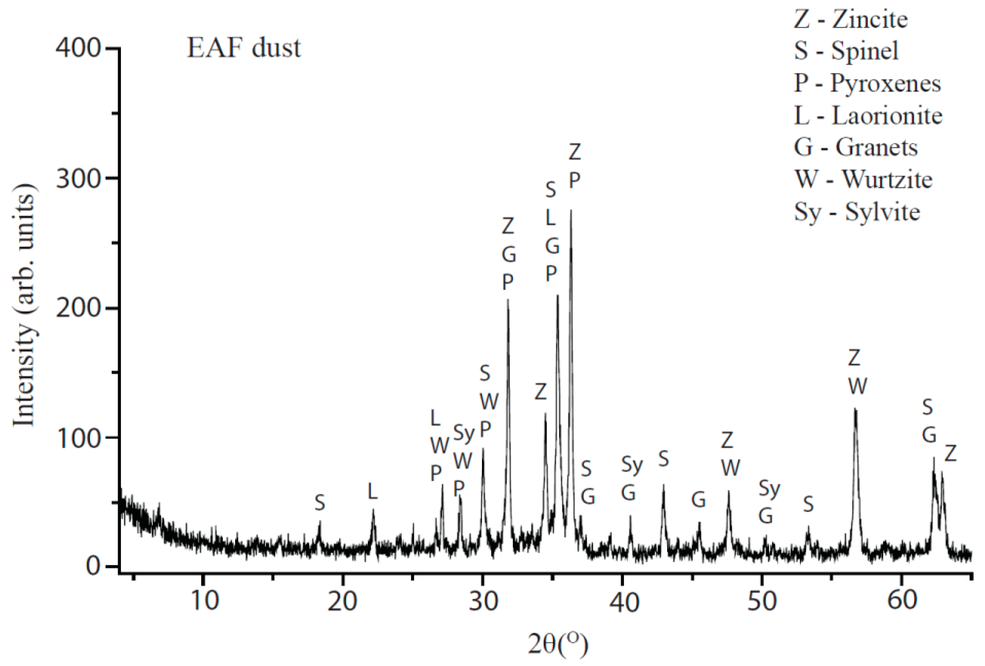
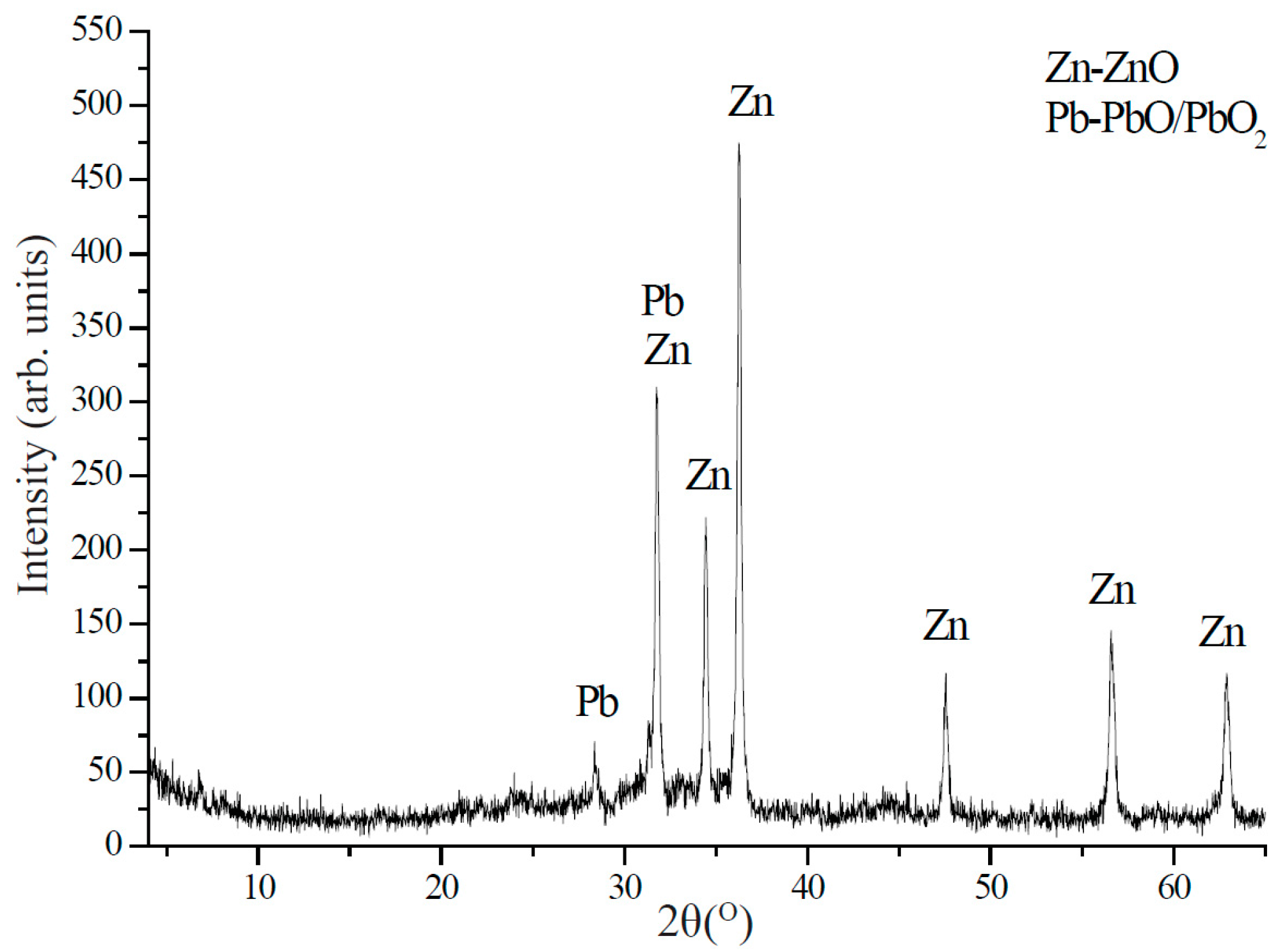
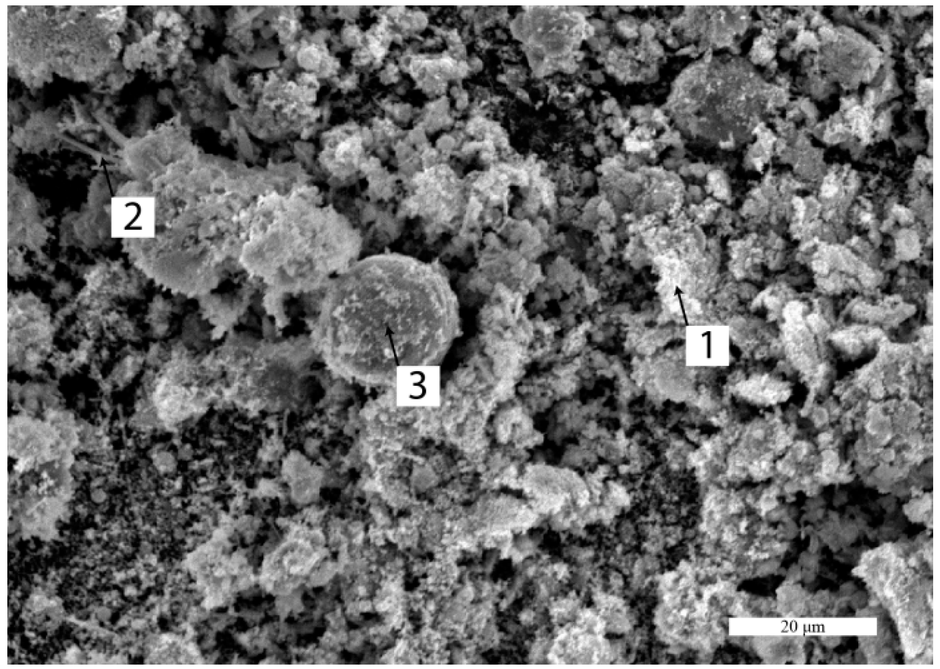
4.1. Dust Characterization

The dynamic conditions in the furnace provide a good fuming effect, as evidenced from a high transition of Zn, Pb, and Cd into the dust. The dust weight was 13.1% ± 0.3% of the input materials weight. Transition of zinc was 97 ± 1.9 wt. %, lead 96 ± 1.2 wt. %, and cadmium 95 ± 1.8 wt. %. The chemical composition of the dust is given in Table 7.
With XRD analysis, ZnO and PbO/PbO2 phases were found, as it is shown in Figure 7.
The phases, based on Fe and Cd, were not found due to their low content in the dust. With SEM-EDS analysis, a high content of lead was found in needle-like formations (Figure 8, item 2). According to the EDS analysis, the chemical composition in item 2 is 14.9 wt. % Pb; 43.1 wt. % Zn; 4.3 wt. % Fe; 4.1 wt. % Cl; 33.1 wt. % O. The high content of Fe was found on the spherical shapes covered with Zincite (Figure 8, item 3). The chemical composition in item 3 is 7.6 wt. % Fe; 55.3 wt. % Zn; 0.1 wt. % Pb; 17.1 wt. % Cl; 19.3 wt. % O. The small particles of ZnO form larger agglomerates in a range from few microns to 20 μm (Figure 8, item 1). The chemical composition in item 1 is 71.1 wt. % Zn; 0.4 wt. % Pb; 0.1 wt. % Fe; 0.2 wt. % Cl; 27.8 wt. % O.

4.2. Metal Composition

Since the iron weight was 31.1% ± 0.6% of the overall input materials weight that indicates that the transition of Fe from the input materials to the iron is 84 ± 1.3 wt. %. The chemical composition of the produced material obtained from the melting process is given in Table 8. The relatively high Cu-content reduces the quality of the iron product. The tolerable content of copper in the deep draw quality steel plate is 0.6%, in the bar steel is 0.4%, in the shape steel 0.3%, in the hot or cold rolled sheet is 0.1% [30].

4.3. Slag Characterization

The weight of the slag was 23.0% ± 0.5% of the input material weight. Chemical composition, optical microscopy in polarized light and XRD analysis confirmed the presence of mineral phases, characteristic for the basic slag, as it was modeled. Based on equation 3 and chemical composition from the Table 9, basicity of the slag is 1.25.
A diffraction pattern (Figure 9) clearly shows that the most common phase is gehlenite; minor phases are magnetite, granets, and quartz. The presence of jacobsite (MnFe2O4) and hercynite (FeAl2O4) is questionable because there are no independent reflections.
Microscopic studies with polarized light confirm that the gehlenite (2CaOAl2O3SiO2) is the most dominant phase, which was isolated in the regular short prismatic crystals forms (Figure 10a, item 1) from a vitreous basis with the same composition (Figure 10a, item 2). Magnetite is also present, formed by the reduction of the primary hematite and by decay of wustite during the cooling of the slag (Figure 10, item 3). With the transmitted light method, the dendritic phases of merwinite (3CaOMgO2SiO2) (Figure 10b, item 1) and melilite (Figure 10b, item 2) which represents a solid solution of akermanite (2CaOMgO2SiO2) and gehlenite, are clearly observed. From silicate mineral, the larnite (β2CaOSiO2) formed by dissociation of rankinite (3CaO2SiO2) (Figure 10a, item 4 and Figure 10b, item 3) is present.
Slags based on the gehlenite phase are completely stable and insoluble in a basic and neutral environment, thus they are a good replacement for traditional raw materials in civil engineering applications [31]. On the other hand, the gehlenite phase inhibits formation of larnite, preventing disintegration of this soluble phase in the environment [31].

4.4. Monitoring of Exhaust Gases

The gas emission monitoring from the multiphase reactive smelting process is a good way for indirect monitoring of the process behavior. The emissions of CO, NOx, and SO2 were measured inside the three periods of the smelting process: (1) introducing the input materials in the batch at low temperatures in the furnace; (2) melting the batch by increasing the furnace temperature; (3) introducing the materials in the batch at high temperatures in the furnace. Results are shown in Figure 11. In the beginning of a smelting process, temperatures were relatively low (under 973 K), therefore, the carbon monoxide was not produced. In this period of the process, a higher share of NOx and SO2 was recorded. The sulphur from the input materials was released and reacted with oxygen, but soon was exhausted due to its low content in the pellets, as it is shown in the period two, Figure 11. In the second period the temperature was increased, the carbon-monoxide was detected and its content was increased with time. The reduction atmosphere in the furnace does not allow formation of NOx. At the third period, a temperature over 1773 K was achieved, and a new amount of materials was introduced into the furnace. The sulphur content is much lower than in the first period, indicating that some of the sulphur reacts in the furnace, probably with the copper and the iron. Due to the rapid carbon reaction with metal oxides, content of CO(g) was high, it was decreased with time in this period because the carbon content in the pellets was reduced. At the end of this period new materials were introduced, and until the end of the process the emission graph behaved as in the third period. The emission graph is a good indicator for adjusting the material introduction periods.
As it can be seen from Figure 11 in the third period, which is the typical process period, just before the sulphur is burned and CO is at a low level the new input materials should be introduced.

5. Conclusions

The designed mixture was pelletized and smelted in the laboratory scale DC electric arc furnace with the energy consumption of 1930 kWh/t Fe. Transition of the Fe from waste to the metallic iron was 84 wt. %, and transition of the Cd, Zn, and Pb to the dust was 95, 97, and 96 wt. %, respectively. The quality of iron is poor due to the relatively high copper content, and some additional steps are required for dust treatment [32]. The slag composition indicates that basicity was above 1.2 as it was proven with microstructure analysis. The microstructure analysis of the slag indicates that the gehlenite phase is dominant, which makes it favorable for use in civil engineering applications. Monitoring of the exhausted gases was done during the three periods of material introduction; that was shown as a good method for tracking the process flow and indicating the optimal material introduction times. The validity of the model for multiphase reactive smelting of synergistic wastes was confirmed.
Detailed thermo-chemical analysis of major compounds from the EAF dust and the mill-scale with reducing agent in the metal-slag-gas phases is essential for setting a model with good material management and energy efficiency. The chemistry of the slag was designed to provide basicity above 1.2, which will provide a good viscosity and improve the process efficiency. The optimal ratio in the mixture is 45% of the EAF dust and 55% of the mill scale, which will require energy consumption for its melting of 1660 kWh per ton of the produced iron. For complete reduction of oxides in this mixture, simulation using the RikiAlC software indicated that 16.2% of the coke is necessary.

Acknowledgments

The authors wish to acknowledge the financial support from the Ministry of Education and Science of the Republic of Serbia through the projects TR34033.

Author Contributions

V.M., Ž.K. conceived and designed the experiments; M.G. performed the experiments; M.K. analyzed the data; M.S. contributed reagents/materials/analysis tools; V.M. wrote the paper.

Conflicts of Interest

The authors declare no conflict of interest.

References

  1. Grabda, M.; Oleszek, S.; Shibata, E.; Nakamura, T. Study on simultaneous recycling of EAF dust and plastic waste containing TBBPA. J. Hazard. Mater. 2014, 278, 25–33. [Google Scholar] [CrossRef] [PubMed]
  2. Taheri, A.M.; Saidi, A.; Nourbakhsh, A.A. The effective parameters on thermal recovery and reduction of iron oxides in EAF slag. Int. J. ISSI 2010, 7, 25–29. [Google Scholar]
  3. Itoh, S.; Tsubone, A.; Yokoyama, K.M.; Nakajima, K.; Nagasaka, T. New EAF Dust Treatment Process with the Aid of Strong Magnetic Field. ISIJ Int. 2008, 48, 1339–1344. [Google Scholar] [CrossRef]
  4. Montenegro, V.; Oustadakis, P.; Tsakiridis, P.; Leonardou, S.A. Hydrometallurgical Treatment of Steelmaking Electric Arc Furnace Dusts (EAFD). Metall. Mater. Trans. B 2013, 44B, 1058–1069. [Google Scholar] [CrossRef]
  5. Santos, F.; Brocchi, E.; Araujo, V.; Souza, R. Behavior of Zn and Fe Content in Electric Arc Furnace Dust as Submitted to Chlorination Methods. Metall. Mater. Trans. B 2015. [Google Scholar] [CrossRef]
  6. Morcali, M.H.; Yucel, O.; Aydin, A.; Verin, B. Carbothermic reduction of electric arc furnace dust and calcination of waelz oxide by semi-pilot scale rotary furnace. J. Min. Metall. Sect. B Metall. 2012, 48, 173–184. [Google Scholar] [CrossRef]
  7. Shatokhaa, V.I.; Gogenko, O.O.; Kripak, S.M. Utilising of the oiled rolling mills scale in iron ore sintering process. Resour. Conserv. Recycl. 2011, 55, 435–440. [Google Scholar] [CrossRef]
  8. Gavrilovski, M.; Manojlovic, V.; Kamberovic, Z.; Korac, M.; Sokic, M. Semi-empirical software for the aluminothermic and carbothermic reactions. Metall. Mater. Eng. 2014, 20, 199–206. [Google Scholar] [CrossRef]
  9. Zivanovic, P.; Gavrilovski, M.; Stopic, S.; Matic, S.; Lajic, Z.; Tiano, A. The calculation and analysis of the adiabatic temperature of self-propagating high-temperature synthesis in CaWO4 + Mg(Al) system. Metall. Mater. Eng. 2005, 11, 339–344. [Google Scholar]
  10. Wu, C.C.; Chang, F.C.; Chen, W.S.; Tsai, M.S.; Wang, Y.N. Reduction behavior of zinc ferrite in EAF-dust recycling with CO gas as a reducing agent. J. Environ. Manag. 2014, 143, 208–213. [Google Scholar] [CrossRef] [PubMed]
  11. Machadoa, J.G.M.S.; Brehm, F.A.; Moraes, C.A.M.; Santos, C.A.; Vilela, A.C.F.; Cunha, J.B.M. Chemical, physical, structural and morphological characterization of the electric arc furnace dust. J. Hazard. Mater. 2006, 136, 953–960. [Google Scholar] [CrossRef] [PubMed]
  12. Lee, G.S.; Song, Y.J. Recycling EAF dust by heat treatment with PVC. Miner. Eng. 2007, 20, 739–746. [Google Scholar] [CrossRef]
  13. Yoo, J.M.; Kim, B.S.; Lee, J.C.; Kim, M.S.; Nam, C.W. Kinetics of the Volatilization Removal of Lead in Electric Arc Furnace Dust. Mater. Trans. 2005, 46, 323–328. [Google Scholar] [CrossRef]
  14. Issa, H.; Kamberovic, Z.; Gavrilovski, M.; Korac, M.; Andjic, Z. Modeling of metallurgical properties of sinter mixtures of nonstandard raw iron-bearing materials. Met. Int. 2013, 18, 5–8. [Google Scholar]
  15. Kim, B.S.; Yoo, J.M.; Park, J.T.; Lee, J.C. A kinetic study of the carbothermic reduction of zinc oxide with various additives. Mater. Trans. 2006, 47, 2421–2426. [Google Scholar] [CrossRef]
  16. Bafghi, M.S.; Karimi, M.; Adeli, M. A kinetic study on the carbothermic reduction of zinc oxide from electric arc furnace dust. Iranian J. Mater. Sci. Eng. 2013, 10, 18–30. [Google Scholar]
  17. Seetharaman, S.; McLean, A.; Guthrie, R.; Sridhar, S. Treatise on Process Metallurgy, Volume 1: Process Fundamentals; Elsevier: Oxford, UK, 2014. [Google Scholar]
  18. Lopez, F.A.; Delgado, A.L. Enhancement of electric arc furnace dust by recycling to electric arc furnace. J. Environ. Eng. 2002, 128, 1169–1174. [Google Scholar] [CrossRef]
  19. Pickles, C.A. Thermodynamic analysis of the selective carbothermic reduction of electric arc furnace dust. J. Hazard. Mater. 2008, 150, 265–278. [Google Scholar] [CrossRef] [PubMed]
  20. Zhang, H.; Li, J.; Xu, A.; Yang, Q.; He, D.; Tian, N. Carbothermic reduction of zinc and iron oxides in electric arc furnace dust. J. Iron. Steel Res. Int. 2014, 21, 427–432. [Google Scholar] [CrossRef]
  21. Li, X.; Xiao, W.; Liu, W.; Liu, G.; Peng, Z.; Zhou, Q.; Qi, T. Recovery of alumina and ferric oxide from Bayer red mud rich in iron by reduction sintering. Trans. Nonferrous Met. Soc. China 2009, 19, 1342–1347. [Google Scholar] [CrossRef]
  22. Pickels, C.A. Thermodynamic modelling of the multiphase pyrometallurgical processing of electric arc furnace dust. Miner. Eng. 2009, 22, 977–985. [Google Scholar] [CrossRef]
  23. Seetharaman, S.; McLean, A.; Guthrie, R.; Sridhar, S. Electric Furnace Steelmaking. In Treatise on Process Metallurgy, Volume 3: Industrial Processes, Part A; Elsevier: Oxford, UK, 2014. [Google Scholar]
  24. Ramakrishna, G.; Kadrolkar, A.; Srikakulapu, N.G. Exergy and its efficiency calculations in ferrochrome production. Metall. Mater. Trans. B 2015, 46B, 1073–1081. [Google Scholar] [CrossRef]
  25. Wang, H.; Yu, H.; Teng, L.; Seetharaman, S. Evaluation on Material and Heat Balance of EAF Processes with Introduction of CO2. J. Min. Metall. Sect. B Metall. 2016, 52, 01–08. [Google Scholar] [CrossRef]
  26. Kowalski, M.; Spencer, P.J.; Neuschutz, D. Phase Diagrams. In Verein Deutscher Eisenhuttenleute, Slag Atlas, 2nd ed.; Verlag Stahleisen GmbH: Dusseldorf, Germany, 1995; pp. 21–214. [Google Scholar]
  27. Muller, J.; Zietsman, J.H.; Pistorius, P.C. Modeling of Manganese Ferroalloy Slag Properties and Flow During Tapping. Metall. Mater. Trans. B 2015, 46B, 2015–2639. [Google Scholar] [CrossRef]
  28. Mills, K.C. Viscosities of Molten Slags. In Verein Deutscher Eisenhuttenleute, Slag Atlas, 2nd ed.; Verlag Stahleisen GmbH: Dusseldorf, Country, 1995; pp. 349–402. [Google Scholar]
  29. Degterov, S.A.; Jak, E.; Hayes, P.C.; Pelton, A.D. Experimental Study of Phase Equilibria and Thermodynamic Optimization of the Fe-Zn-O System. Metall. Mater. Trans. B 2001, 32B, 643–657. [Google Scholar] [CrossRef]
  30. Katayama, H.; Sano, N.; Sasabe, M.; Matsuoka, S. Research Activities on Removal of Residual Elements from Steel Scrap in Japan. Mem. Fac. Sci. Eng. Shimane Univ. 1997, 30, 99–144. [Google Scholar]
  31. Mombelli, D.; Mapelli, C.; Barella, S.; Gruttadauria, A.; le Saout, G.; Gracia-Diaz, E. The efficiency of quartz addition on electric arc furnace (EAF) carbonsteel slag stability. J. Hazard. Mater. 2014, 279, 586–596. [Google Scholar] [CrossRef] [PubMed]
  32. Joint Research Centre. Best Available Techniques (BAT) Reference Document for the Non-Ferrous Metals Industries; European Commission: Seville, Spain, 2014; pp. 700–704. [Google Scholar]
Figure 1. Cross-section of the laboratory scale DC electric arc furnace.
Metals 06 00138 g001
Figure 2. XRD analysis of the EAF dust.
Metals 06 00138 g002
Figure 3. The Gibbs free energy changes for the related reactions.
Metals 06 00138 g003
Figure 4. The vapor pressure changes with temperature.
Metals 06 00138 g004
Figure 5. Energy consumption during the reduction of the pellets.
Metals 06 00138 g005
Figure 6. Liquidus surface in the slag system of CaO-SiO2-FeOt.
Metals 06 00138 g006
Figure 7. XRD analysis of crude ZnO dust.
Metals 06 00138 g007
Figure 8. SEM analysis of crude ZnO dust.
Metals 06 00138 g008
Figure 9. XRD analysis of slag.
Metals 06 00138 g009
Figure 10. Microstructure of slag. (a) Reflected light; (b) transmitted light.
Metals 06 00138 g010
Figure 11. Emission of CO, NOx, and SO2 in three periods of the smelting process.
Metals 06 00138 g011
Table 1. The composition of the starting slag, in wt. %.
CaOSiO2FeOMgOAl2O3MnONa2OK2OCuSZnNi
36.926.612.59.69.81.60.600.600.100.200.100.30
Table 2. EAF dust chemical composition, in wt. %.
FeSiZnCCdMnCaAlNaKPbMgCu
20.781.6530.683.110.227.123.060.250.531.443.681.430.45
O (oxides)F (fluorides)Cl (chlorides)S (sulfides)Others
20.520.082.691.630.68
Table 3. Mill scale chemical composition, in wt. %.
FeSiCrSnNiCPSMnCaAlMgCuOLOIOthers
70.870.800.040.010.030.020.030.030.090.390.110.130.3025.21.800.12
Table 4. The Lime chemical composition, in wt. %.
CaOAl2O3MgOSiO2
95.71.12.40.60
Table 5. The Coke chemical composition, in wt. %.
CSiO2Al2O3CaOMgOFe2O3S
86.85.74.70.800.500.700.60
Table 6. Material balance of the melting process.
BalanceInput, kgOutput, kg
PelletsStarting SlagSlagMetalDustGas
Model851524.833.813.328.1
Experimental85 ± 0.515 ± 0.123.0 ± 0.531.1 ± 0.613.1 ± 0.3-
Table 7. Material balance of the melting process.
ElementZnFePbCdCl(Chlorides)O(Oxides)Others
wt. %71.10.48.50.51.118.10.3
Table 8. Chemical composition of iron.
ElementFeCMnSiCuSPNiCrSnZnOthers
wt. %90.32.75.40.750.300.100.120.050.030.060.030.16
Table 9. Chemical composition of the slag.
PhaseSiO2CaOFeOMgOAl2O3MnONa2OK2OCuSOthers
wt. %27.836.511.610.19.42.30.30.80.10.20.9

