
Experimental Verification of Statistically Optimized Parameters for Low-Pressure Cold Spray Coating of Titanium

Abstract
:
1. Introduction
2. Mathematical Modeling
2.1. Modeling Assumptions
- (1)
- Ideal gas law is obeyed by the carrier gas.
- (2)
- The gas flow is one-dimensional, frictionless, and adiabatic.
- (3)
- Steady-state conditions exist.
- (4)
- Gas expansion is uniform; no shocks or discontinuities.
- (5)
- Particles effect on gas conditions is negligible.
- (6)
- Inter-particle collision is negligible.
- (7)
- Particles effect on space charge is negligible.
2.2. Model Equations
2.2.1. The Continuity Equation
2.2.2. The Momentum Equation
2.2.3. The Energy Equation
2.2.4. The Constitutive Equation
2.2.5. The Discrete Equations
2.3. Thermo-Physical Properties and Boundary Conditions
2.4. Experimental Details
3. Results and Discussion
3.1. Exit Velocity
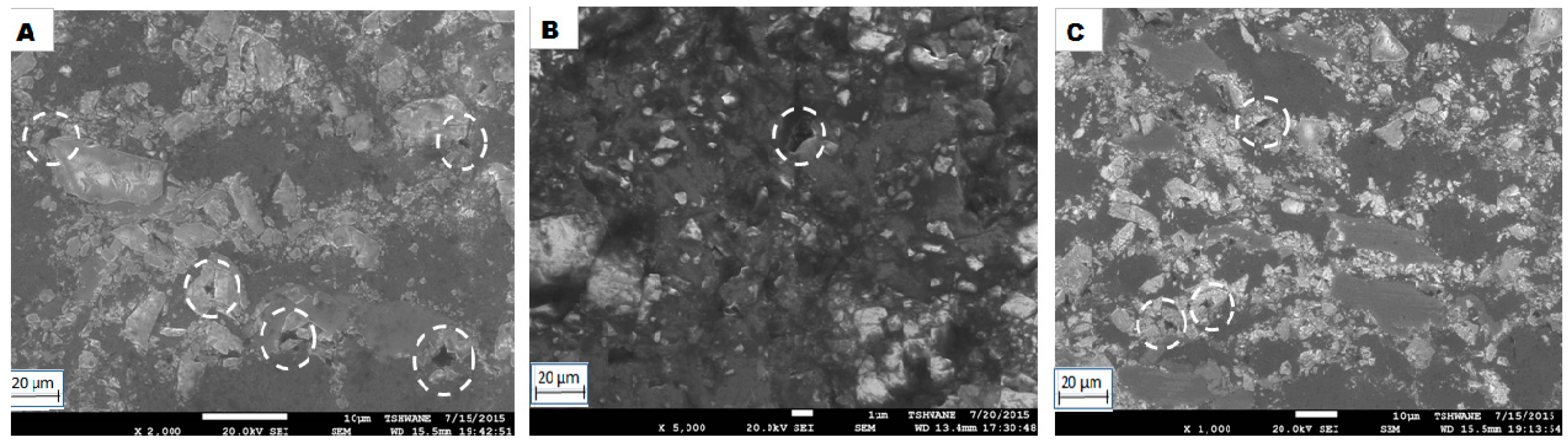
3.2. Microstructure and Porosity of the Coatings
3.3. Hardness of the Coatings
4. Conclusions
Acknowledgments
Author Contributions
Conflicts of Interest
Abbreviations
| ρg | gas (air) density |
| δg | Kronecker delta, which is a component of the identity tensor defined such that δij = 1 if i = j, otherwise δij = 0 |
| ν | velocity vector |
| τ | stress tensor |
| μ | molecular viscosity |
References
- Adebiyi, D.I.; Popoola, A.P.I.; Pityana, S.L. Phase constituents and microhardness of laser alloyed Ti-6Al-4V alloy. J. Laser Appl. 2015, 27, S29104. [Google Scholar] [CrossRef]
- Adebiyi, D.I.; Popoola, A.P.I. Mitigation of abrasive wear damage of Ti-6Al-4V by laser surface alloying. Mater. Des. 2015, 74, 67–75. [Google Scholar] [CrossRef]
- Sahasrabudhe, H.; Soderlind, J.; Bandyopadhyay, A. Laser processing of in situ TiN/Ti composite coating on titanium. J. Mech. Behav. Biomed. Mater. 2016, 53, 239–249. [Google Scholar] [CrossRef] [PubMed]
- Ravindra, D.; Patten, J. Ductile regime single point diamond turning of CVD-SiC resulting in an improved and damage-free surface. In Proceedings of the 4th International Conference on Recent Advances in Materials, Minerals & Environment and 2nd Asian Symposium on Materials & Processing, Penang, Malaysia, 1–3 June 2009.
- Tului, M.; Giambi, B.; Lionetti, S.; Pulci, G.; Sarasini, F.; Valente, T. Silicon carbide based plasma sprayed coatings. Surf. Coat. Technol. 2012, 207, 182–189. [Google Scholar] [CrossRef]
- Moridi, A.; Hassani-Gangaraj, S.M.; Guagliano, M.; Dao, M. Cold spray coating: Review of material systems and future perspectives. Surf. Eng. 2014, 30, 369–395. [Google Scholar] [CrossRef]
- Villafuerte, J. Recent trends in cold spray technology: Looking at the future. Surf. Eng. 2010, 26, 393–394. [Google Scholar] [CrossRef]
- Goyal, T.; Prince, S.; Walia, R.S.; Sidhu, T.S. Effect of nozzle geometry on exit velocity, temperature and pressure for cold spray process. Int. J. Mat. Sci. Eng. 2011, 2, 65–72. [Google Scholar]
- Tria, S.; Elkedim, O.; Li, W.Y.; Liao, H. Ball milled Ni-Ti powder deposited by cold spraying. J. Alloy. Compd. 2009, 483, 334–336. [Google Scholar] [CrossRef]
- Champagne, V. The Cold Spray Materials Deposition Process: Fundamentals and Application; Woodhead: Cambridge, UK, 2007. [Google Scholar]
- Ghelichi, R.; Bagherifard, S.; Guagliano, M.; Verani, M. Numerical simulation of cold spray coating. Surf. Coat. Technol. 2011, 205, 5294–5301. [Google Scholar] [CrossRef]
- Gartner, F. Advances in cold spraying. Surf. Eng. 2006, 22, 161–163. [Google Scholar] [CrossRef]
- Schmidt, T.; Gaurtner, F.; Assadi, H.; Kreye, K. Development of a generalized parameter window for cold spray deposition. Acta Mater. 2006, 54, 729–742. [Google Scholar] [CrossRef]
- Assadi, H.; Gaurtner, F.; Stoltenhoff, T.; Kreye, H. Bonding mechanism in cold gas spraying. Acta Mater. 2003, 51, 4379–4394. [Google Scholar] [CrossRef]
- Alkimov, A.P.; Kosarev, V.E.; Papyrin, A.N. A method of cold gas-dynamic deposition. Dokl. Akad. Nauk. SSSR 1990, 318, 1062–1065. [Google Scholar]
- Legoux, J.G.; Irissou, E.; Moreau, C. Effect of substrate temperature on the formation mechanism of cold-sprayed aluminum, zinc and tin coatings. J. Therm. Spray Technol. 2007, 16, 619–626. [Google Scholar] [CrossRef]
- Gao, P.; Li, C.; Yang, C.; Li, Y.; Li, C. Influence of substrate hardness on deposition behavior of single porous WC-12Co particle in cold spraying. Surf. Coat. Technol. 2008, 203, 384–390. [Google Scholar] [CrossRef]
- Li, C.J.; Wang, H.T.; Zhang, Q.; Yang, G.J.; Li, W.Y.; Liao, H.L. Influence of spray materials and their surface oxidation on the critical velocity in cold spraying. J. Therm. Spray Technol. 2010, 19, 95–101. [Google Scholar] [CrossRef]
- Yokoyama, K.; Watanabe, M.; Kuroda, S.; Gotoh, Y.; Schmidt, T.; Gartner, F. Simulation of solid particle impact behaviour for spray processes. J. Mater. Trans. 2006, 47, 1697–1702. [Google Scholar] [CrossRef]
- Henao, J.; Concustell, A.; Cano, I.G.; Cinca, N.; Dosta, S.; Guilemany, J.M. Influence of Cold Gas Spray process conditions on the microstructure of Fe-based amorphous coatings. J. Alloy. Compd. 2015, 622, 995–999. [Google Scholar] [CrossRef]
- Li, C.J.; Li, W.Y.; Liao, H. Examination of the Critical Velocity for Deposition of Particles in Cold Spraying. J. Therm. Spray Technol. 2006, 15, 213. [Google Scholar] [CrossRef]
- Sun, J.G.; Kim, H.D.; Park, J.O.; Jin, Y.Z. A Computational study of the gas-solid suspension flow through a supersonic nozzle. Open J. Fluid Dyn. 2012, 2, 242–247. [Google Scholar] [CrossRef]
- Dmitrienko, G.S.; Uvarova, L.A. Modeling of dendritic growth in two dimensions. Int. J. Pure Appl. Math. 2013, 82, 663–668. [Google Scholar] [CrossRef]
- Vutova, K.; Donchev, V. Electron beam melting and refining of metals: Computational modeling and optimization. Materials 2013, 6, 4626–4640. [Google Scholar] [CrossRef]
- Goyal, T.; Sidhu, T.S.; Walia, R.S. Taguchi Based Optimization for Micro Hardness of Cold Spray Coating Process. Intl. J. Surf. Eng. Interdiscip. Mat. Sci. 2014, 2, 23–33. [Google Scholar] [CrossRef]
- Papyrin, A.N. Cold Spray: State of the Art and Applications; Cold spray technology: Albuquerque, NM, USA, 2006; pp. 1–21. [Google Scholar]
- Lee, J.C.; Kang, H.G.; Chu, W.S.; Ahn, W.S. Repair of damaged mold surface by cold-spray method. CIRP Ann. Manuf. Technol. 2007, 56, 577–580. [Google Scholar] [CrossRef]
- Lin, J.; Ruan, X.; Chen, B. Fluid Mechanics; Tsinghua University Press: Beijing, China, 2005; pp. 72–91. [Google Scholar]
- Chuayjan, W.; Pothiphan, S.; Wiwatanapataphee, B.; Wu, Y.H. Numerical simulation of granular flow during filling and discharging of a silo. Int. J. Pure Appl. Math. 2010, 62, 347–364. [Google Scholar]
- Reddy, J.N.; Gartling, D.K. The Finite Element Method in Heat Transfer and Fluid Dynamics; CRC Press: London, UK, 1994. [Google Scholar]
- Lupoi, R. Current design and performance of cold spray nozzles: Experimental and numerical observations on deposition efficiency and particle velocity. Surf. Eng. 2014, 30, 316–322. [Google Scholar] [CrossRef]
- Lee, M.W.; Park, J.J.; Kim, D.Y.; Yoon, S.S.; Kim, H.Y.; Kim, D.H.; Park, D.S. Optimization of supersonic nozzle flow for titanium dioxide thin-film coating by aerosol deposition. J. Aerosol. Sci. 2011, 42, 771–780. [Google Scholar] [CrossRef]
- Li, C.J.; Li, W.Y.; Liao, H. Examination of the critical velocity for deposition of particles in cold spraying. J. Therm. Spray. Technol. 2006, 15, 212–222. [Google Scholar] [CrossRef]
- Motta, F.V.; Balestra, R.M.; Ribeiro, S.; Taguchi, S.P. Wetting behaviour of SiC ceramics: Part I. E2O3/Al2O3 additive system. Mater. Lett. 2004, 58, 2805–2809. [Google Scholar] [CrossRef]
- Adebiyi, D.I.; Botef, I.; Popoola, P.A. Computational technique for optimization of the process parameter for cold spray coating of titanium. In Proceedings of the 1st International Conference on Mathematical Methods & Computational Techniques in Science & Engineering, Athens, Greece, 28–30 November 2014; pp. 239–243.
- Geels, K.; Fowler, D.B.; Kopp, W.U.; Ruckert, M. Metallographic and Materialographic Specimen Preparation, Light Microscopy, Image Analysis, and Hardness Testing; ASTM International: West Conshohocken, PA, USA, 2007. [Google Scholar]
- ASTM Standard. E384-11E1, Standard Test Method for Knoop and Vickers Hardness of Materials; ASTM International: West Conshohocken, PA, USA, 2007. [Google Scholar] [CrossRef]
- ASTM Standard. C1327, Standard Test Method for Vickers Indentation Hardness of Advanced Ceramics; ASTM International: West Conshohocken, PA, USA, 2008. [Google Scholar] [CrossRef]
- Konecna, R.; Nicoletto, G.; Majerova, V. Largest extreme value determination of defect size with application to cast Al-Si alloys porosity. Metal 2007, 16, 94. [Google Scholar]
- Ganvir, A.; Curry, N.; Bjorklund, S.; Markocsan, N.; Nylen, P. Characterization of Microstructure and Thermal Properties of YSZ Coatings Obtained by Axial Suspension Plasma Spraying (ASPS). J. Therm. Spray Technol. 2015, 1, 1–10. [Google Scholar] [CrossRef]
- Moore, E.M.; Papavassiliou, D.V.; Shambaugh, R.L. Air velocity, air temperature, fiber vibration and fiber diameter measurements on a practical melt blowing die. Int. Nonwovens J. 2004, 13, 43–53. [Google Scholar]
- Huang, R.Z.; Fukanuma, H. The Influence of Spray Conditions on Deposition Characteristics of Aluminum Coatings in Cold Spraying. In Proceedings of the International Thermal Spray Conference, 4–7 May 2009; Marple, B.R., Hyland, M.M., Lau, Y.-C., Eds.; Thermal Spray 2009: Las Vegas, Nevada, USA, 2009; pp. 279–284. [Google Scholar] [CrossRef]
- Khalid, A.A. The effect of testing temperature and volume fraction on impact energy of composites. Mater. Des. 2006, 27, 499–506. [Google Scholar] [CrossRef]
- Triantou, K.I.; Pantelis, D.I.; Guipont, V.; Jeandin, M. Microstructure and tribological behavior of copper and composite copper+alumina cold sprayed coatings for various alumina contents. Wear 2015, 336, 96–107. [Google Scholar] [CrossRef]
- Medica, L.A. Guidelines for Safe Handling of Powders and Bulk Solids; Wiley: Hoboken, NJ, USA, 2004. [Google Scholar]
- Smith, G.T. Industrial Metrology: Surfaces and Roundness; Springer Science & Business Media: New York, NY, USA, 2013; p. 202. [Google Scholar]


| Carrier Gas (Air) | SiC Powder | ||
|---|---|---|---|
| Density | 1.205 kg/m3 | Density | 3160 kg/m3 |
| Specific heat capacity, Cp | 1.005 J/kg·K | Heat capacity, C | 675 J·kg−1·K−1 |
| Thermal conductivity, h | 0.0257 W/m·K | Thermal conductivity | 490 W·m−1·K−1 |
| Kinematic viscosity, v | 15.11 ×10⁻⁶ m2/s | Elastic modulus, E | 570 MPa |
| Expansion coefficient | 3.43 × 10⁻³ 1/K | Poisson ratio, μ | 0.17 |
| Prandtl’s number, Pr | 0.713 | ||
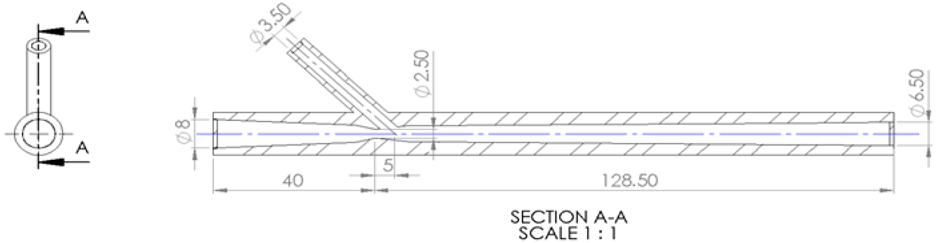
| Section of the Nozzle | (mm) |
|---|---|
| Throat diameter | 4 |
| Nozzle entrance diameter | 8 |
| Nozzle exit diameter | 6 |
| Length of converging section | 50 |
| Length of diverging section | 125 |
© 2016 by the authors; licensee MDPI, Basel, Switzerland. This article is an open access article distributed under the terms and conditions of the Creative Commons Attribution (CC-BY) license (http://creativecommons.org/licenses/by/4.0/).
Share and Cite
Adebiyi, D.I.; Popoola, A.P.; Botef, I. Experimental Verification of Statistically Optimized Parameters for Low-Pressure Cold Spray Coating of Titanium. Metals 2016, 6, 135. https://doi.org/10.3390/met6060135
Adebiyi DI, Popoola AP, Botef I. Experimental Verification of Statistically Optimized Parameters for Low-Pressure Cold Spray Coating of Titanium. Metals. 2016; 6(6):135. https://doi.org/10.3390/met6060135
Chicago/Turabian StyleAdebiyi, Damilola Isaac, Abimbola Patricia Popoola, and Ionel Botef. 2016. "Experimental Verification of Statistically Optimized Parameters for Low-Pressure Cold Spray Coating of Titanium" Metals 6, no. 6: 135. https://doi.org/10.3390/met6060135