Article

Effect of Friction Stir Welding Parameters on the Mechanical and Microstructure Properties of the Al-Cu Butt Joint

1
Department of Mechanical Engineering, Faculty of Engineering and Architecture, Balikesir University, Balikesir 10145, Turkey
2
Personnel Recruitment Resources, Turkish Land Forces, Ankara 06590, Turkey
*
Author to whom correspondence should be addressed.
Metals 2016, 6(6), 133; https://doi.org/10.3390/met6060133
Submission received: 7 April 2016 / Revised: 10 May 2016 / Accepted: 23 May 2016 / Published: 31 May 2016
(This article belongs to the Special Issue Aluminum Alloys)

Abstract

:
Friction Stir Welding (FSW) is a solid-state welding process used for welding similar and dissimilar materials. FSW is especially suitable to join sheet Al alloys, and this technique allows different material couples to be welded continuously. In this study, 1050 Al alloys and commercially pure Cu were produced at three different tool rotation speeds (630, 1330, 2440 rpm) and three different tool traverse speeds (20, 30, 50 mm/min) with four different tool position (0, 1, 1.5, 2 mm) by friction stir welding. The influence of the welding parameters on the microstructure and mechanical properties of the joints was investigated. Tensile and bending tests and microhardness measurements were used to determine the mechanical properties. The microstructures of the weld zone were investigated by optical microscope and scanning electron microscope (SEM) and were analyzed in an energy dispersed spectrometer (EDS). Intermetallic phases were detected based on the X-ray diffraction (XRD) analysis results that evaluated the formation of phases in the weld zone. When the welding performance of the friction stir welded butt joints was evaluated, the maximum value obtained was 89.55% with a 1330 rpm tool rotational speed, 20 mm/min traverse speed and a 1 mm tool position configuration. The higher tensile strength is attributed to the dispersion strengthening of the fine Cu particles distributed over the Al material in the stir zone region.

Graphical Abstract

1. Introduction

Friction Stir Welding (FSW), was invented and patented by The Welding Institute UK (TWI) in 1991 [1]. FSW as a solid-state process has gained a lot of importance due to its advantages such as providing good mechanical properties, especially with aluminum alloy, and quality joints [2,3]. This method has advantages compared to conventional welding methods since there is no distortion, porosity and cracks during the application [4,5]. Very good quality welds have been obtained using FSW in joining aluminum, magnesium, titanium, copper and steel materials. Recently, studies on joining dissimilar materials have been carried out [6,7,8]. The accurate joining of dissimilar materials is very important in terms of its use in important fields including the chemical, nuclear, aerospace, transportation, power generation, and electronics industries [9,10].
Copper and aluminum are important metals for the electrical industry due to their good electrical and thermal conductivity as well as high corrosion resistance and mechanical properties. Many studies for different welding methods have been conducted in order to joint these two materials in high-voltage, direct-current distribution lines; and the different techniques of joining copper/aluminum has become a research subject [11]. However, the welding of aluminum to copper by fusion welding is generally difficult because of the wide difference in their physical, chemical and mechanical properties and the tendency to form brittle intermetallic compounds (IMCs). Therefore, solid-state joining methods such as friction welding, roll welding and explosive welding have received much attention. These methods, however, have a few drawbacks. For example, friction welding and roll welding lack versatility, and there are safety problems involved in explosive welding [12].
Several studies have been carried out on the effects of dissimilar aluminum and copper welding parameters on the microstructure and mechanical properties in the weld zone and the detection of intermetallic phases that occurs in the weld zone [5,13,14,15,16,17]. In fact, several works have already addressed the dissimilar friction stir welding of these materials, in both butt and lap joint configurations. However, Al-Cu lap joining has been much more explored than friction stir butt welding, for which, so far, only a small number of studies have been conducted [8]. The studies have concluded with different results and could not achieve high strengths, yet very few studies have addressed tool positioning parameters. In particular, the effect of the tool positioning on the complex material flow pattern and the resultant properties have not yet been revealed in detail for Al-Cu materials.
In this study, AA1050 with a thickness of a 4 mm is friction stir welded to pure copper sheets at three different tool rotation speeds (630, 1330, 2440 rpm), three different tool traverse speeds (20, 30, 50 mm/min), and four different tool positions (0, 1, 1.5, 2 mm); finally, the mechanical and microstructural properties of the joint are evaluated.

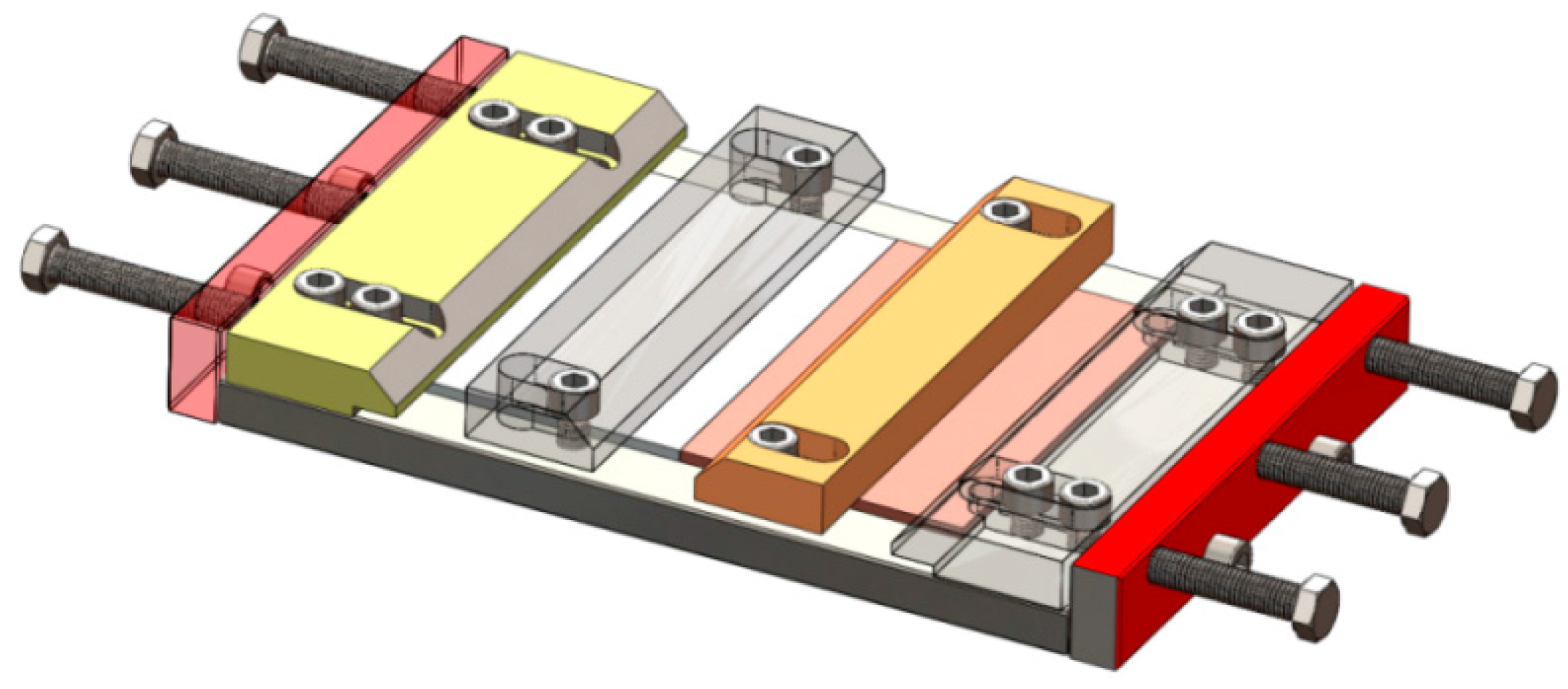
2. Materials and Methods

Pure copper (99.9%) and 1050 aluminum alloy plates with a thickness of 4 mm were joined by FSW. Aluminum and copper plates are prepared in 100 × 150 mm dimensions. The mechanical properties of aluminum and copper that are used in this study is shown in Table 1.
Two materials are positioned on the fixture and it is ensured that they do not draw apart; Cu is leaned to the advancing side, while Al is leaned to the retreating side as shown in Figure 1.
The tool material selected is high-speed steel in order to keep the hardness resistance and avoid corrosion on the stir pin during the process. Heat treatment is applied to the stir pin and a 62HRc value is achieved. A cylindrical tool of M4 × 3.87 mm with a shoulder of 18 mm is used. The welding parameters are determined by preliminary studies and literature. The constant parameters are as follows:
  • Direction of rotation of the tool: Clockwise
  • Tilt Angle: 1.5°
  • Standby Time: 60 s.
Experiments were performed with different sets of rotational and traverse speeds in order to achieve high strength in the welded parts. In these experiments, stir pin was positioned at “0” (zero) on both aluminum and copper plates. Although the welding surface appearance seems proper, gaps in microstructure were formed, as shown in Figure 2. The gaps and welding that was not fully formed cause low mechanical values in the welded parts, and low tensile strength. It was therefore concluded that the welding of the materials was not fully performed. Afterwards, the studies were continued by changing the position of the stir pin. It was positioned to the Al side from the butt center line since it is a softer material compared to Cu. After preliminary trials, with the understanding of the significant importance of the tool positioning, the welding parameters were determined as shown in Table 2. The nomenclature adopted in the text for labelling the different welds will identify the welding condition, i.e., 630/20/1 means 630 rpm of rotational speed, 20 mm·min−1 of traverse speeds and 1 mm of pin positions, respectively.
The tensile specimens were extracted from the weld joint and tested using an electromechanical controlled universal testing machine as per ASTM E8 M-04 guidelines. Three tensile tests have been performed for every welding sample and the average value has been obtained. The strain rate was 2 mm/min. Bending test specimens were prepared perpendicular to the welding direction in accordance with the ASTM E855-08 standard. Two rows of microhardness measurement were made from both the lower and the upper surface of specimens that were perpendicular to the welding section. The first measurement was taken at 0.5 mm below the surface, and the second measurement was taken at 0.5 mm above the lower surface. A sanding process with grit No. from 220 to 1200 according to CAMI grit designation sandpapers was performed on the samples that were taken from the cross section perpendicular to the welding direction in order to detect the microstructural changes at the weld zones after joining. The welded area was polished with 3 µm and 1 µm diamond paste and etched. In the etching process; 100 mL of distilled water, 4 mL of saturated sodium chloric, 2 g of potassium dichromate and an etching reagent consisting of 5 mL sulfuric acid were used for the Cu side; Keller’s solution was used for Al side, and the results were examined with a Nikon Eclipse MA100 optical microscope (Nikon, Tokyo, Japan) in the laboratories of Turkish Land Forces which is located Balikesir, Turkey. In addition, point and linear energy dispersed spectrometer (EDS) analyses were carried out after the examination of the weld zones with a scanning electron microscope (SEM) in the Scientific and Technological Research Council of Turkey (TUBITAK) that is located in Gebze, Turkey. X-ray diffraction (XRD) analysis was conducted to examine the phase occurring in the weld zone.

3. Results and Discussions

Cross sections perpendicular to the welding direction, and the bottom and top surfaces of joints that are formed with dissimilar welding parameters were photographed. Images from the welded parts are given in Figure 3 and Figure 4. By comparing the surface photographs in Figure 3a,b and Figure 4a,b, the differences in surface finishing can be easily observed. Welding defects such as gaps, holes and joint failure were not registered when the bottom and top surface of the welded part were examined. In fact, whereas the 1330/20/1 weld presents a very smooth surface composed of regular and well-defined striations, similar to those obtained in similar copper friction stir welding by Galvão et al. [8], signs of significant tool submerging and the formation of massive flash are observed at the surface of the 630/50/1 weld. It is important to stress that, although both welds have been carried out under the same welding conditions, the 630/50/1 weld surface presents defects usually associated with excessive heat input during friction stir welding. This result is in good agreement with Leitão et al. [18], who studied the influence of base materials properties on defect formation during AA5083 and AA6082 FSW.
Comparing the cross section macrographs of both welds, displayed in Figure 3c and Figure 4c, important differences in the structure and morphology of the bonding area can also be observed. The image of the cross section of the 630/50/1 weld shows that the Al-Cu interaction zone of this weld is restricted to the pin influence zone. Minor evidence of the material stirred by the pin can be observed in Figure 3c, that the total inefficient mixing between the aluminum and copper gave rise to a large discontinuity between both base materials, preventing the effective joining of the plates. In fact, according to Figure 3, the coupling between the two materials only occurred at the advancing side of the tool where the aluminum was pushed into the copper. The cross section macrographs of the 1330/20/1 weld are shown in Figure 4c. From the pictures, it can be concluded that the Cu/Al interaction volume for the 1330/20/1 weld is significantly larger than that observed for the 630/50/1 weld.
A full mixture could not be reached in “0” positioned Al-Cu joining; however, 1, 1.5 and 2 mm tool shifting led to a homogeneous mixture, increasing the mechanical values. Tensile specimens that were friction stir welded with tool shifting are given Figure 5, and the tensile strength test depending on the rotational speed results are given in Figure 6, Figure 7 and Figure 8. The tensile strength of Al and Cu were found to be 111.20 MPa and 231.38 MPa, respectively. As seen in the strength chart, the 1330/20/1 specimen has the highest tensile strength at 99.58 MPa, and the lowest tensile strength is 27.59 MPa in the 630/50/1 specimen. Analyzing the graph in Figure 6, an increment in tensile strength was observed when the tool shifted from 1 mm to 1.5 mm with the same tool speed (630 rpm) and traverse speed (20 mm/min). On the other hand, a slight decrease in strength value was seen when the tool was shifted to 2 mm from the center. Additionally, it is concluded that tensile strength values were increased with the increase of tool positioning in 30 mm/min and 50 mm/min tool speeds. Higher strength values were obtained in conditions with low speeds, high traverse rates and tool positioning since they lead to sufficient welding temperature and weld width.
The highest strength values in welded parts were reached in 1330 rpm rotational speeds as shown in Figure 7. Ideal temperatures occurred in Al-Cu FSW at this rotation speed, so that a thinly dispersed and homogeneous mixture is obtained. The strength of intermetallic phase increases with the effect of heat during FSW, however, it will not be brittle, and this conforms with the literature [13,14].
Figure 8 shows the trials with the highest rotation speed (2440 rpm), and it is observed that the tensile strength of the welded part is increases as the traverse speeds and tool positioning increase. High tensile strength was obtained as can be seen in Figure 8, and 92.91 MPa of tensile strength is reached with 30 mm/min traverse speed and 1 tool shifting condition. However, it is seen that the tensile strength value is decreased under the highest traverse speed (50 mm/min) and tool positioning (2 mm). The reasons for this are the lack of formation of any homogeneous mixture area in the weld zone and the fact that the adequate temperature is not supplied to the joint. Additionally, it is considered that the thickness of intermetallic phases is increased due to high heat input under low traverse speeds (20 mm/min).
The higher tensile strength of the Al-Cu weld joints mainly depends on the distribution of fine particles and the low intermetallic thickness formation and grain boundary strengthening in the nugget zone. Due to the stirring of the tool, the Cu particles were fragmented from the Cu side and distributed in the stir zone. These fine Cu particles were completely transformed into hard brittle intermetallic due to the interfacial reaction with the Al matrix [5,19]. The tensile tests as a whole shows that there is adequate temperature during FSW and so the homogeneous mixture conditions leading to an Al-Cu reaction are reached. As a result of tensile tests, ruptures usually occur in weld zone and heat affected zone (HAZ) in aluminum welds. In the literature, the reason for the rupture occurrences in Al side is explained with two factors; the first is that the formation of the weld zone happened to be on the Al side, and the second factor is that the tensile strength of the base material Al is lower than the other base material Cu [11]. Ruptured surfaces of the specimens that have the highest and the lowest tensile strength are considered for the evaluation. SEM images of the ruptured surfaces are shown in Figure 9 and Figure 10. When the SEM images are examined, it is concluded that the ruptured surface of specimens (Figure 9) that have higher mechanical properties are ductile, while the others’ surface (Figure 10) are brittle. Many dimples in Al side of the rupture surface are found in the 1330/20/1 specimen, and a small amount of dimples are found on the ruptured surface of the 630/50/1 specimen.
Three point bending tests are carried out on the specimens that are cut with a water jet from the welded joints in 20 × 100 mm dimensions. Additionally, base materials have been tested; images can be seen in Figure 11a. The welded specimens are loaded until they take a U-shape or a failure is observed. As shown in Figure 10b, no failure is found on the 1330/20/1 specimen after the bending test. On the other hand, fractures and failures are found in HAZ and welded zones, especially on the specimens that have low tensile strength.
Hardness values are evaluated on the transverse cross section of welded parts. Hardness results measured from the top and bottom plates of the weldments under different parameters are illustrated in Figure 12, Figure 13 and Figure 14. The microhardness values of the base metals were found to be 88 HV for Cu, and 41 HV for Al.
In Figure 12, in analyzing the hardness changes of the specimen 630/50/1, which has low rpm and high traverse speed, it is observed that the weld zone formed is considerably narrow. Similarly, in Figure 13 and Figure 14, the data show that specimens that have medium and high traverse speeds (1330/20/1 and 2440/30/1) have higher tensile strengths and formed larger weld zones compared to the 630/50/1 specimen. A wide weld zone shows the existence of the full mixture of materials. The sudden increase in hardness value in the weld zone, especially on the top plate, is considered to happen because of the intermetallic phases between Al-Cu under the influence of heat during welding. The hardness values in the composite structure were much higher than those of the Al side. This enhanced hardness of the Al matrix should be mainly attributed to the strengthening from the ultrafine grains. Moreover, the hardness of the layered structures was measured as high as 185 HV which was higher than that of the Cu bulk. Previous studies indicated that the hardness of the Al-Cu IMCs was very high compared to that of the Cu, and the maximum hardness value could reach 760 HV [14]. Therefore, the high hardness value of the layered structure originated mainly from the Al-Cu IMCs.
In this study, the microstructures of HAZ on the Al side, Cu side, and weld zones of all specimens are studied in details. Through these studies, it is found that the weld zone is formed on the Al side since the stir pin was positioned to the Al side in specific values (1, 1.5, 2 mm). Moreover, the composite structure between the aluminum and copper is remarkable in Al-Cu FSW joining.
The microstructure of the specimens that have the highest and lowest tensile strength are given in order to compare and evaluate the changes in strength and the structural changes in weld zones. The microstructure of base materials are illustrated in Figure 15a,b, 630/50/1 specimen’s microstructure is given in Figure 16 and Figure 17 represents the 1330/20/1 specimen’s microstructure.
The material is flowing from the advancing side to the retreating side at the front end of the tool. This creates a vacancy in the advancing side. At the rear end, the materials are transported from the retreating side to the advancing side. When the material transported is not large enough to fill the vacancy, a tunnel defect occurred. Under the 630/50/1 parameters, low material flow is observed due to less heat input. Cavities and insufficient mixture are observed as can be seen from Figure 16, and these are the reasons that explain the low strength values.
The microstructure image of the interface between the Al and the Cu is shown in Figure 17. The optimum range of heat was enough to plasticize the Cu material near the area of the interface. Thus, the fine discontinuous Cu particles were detached and distributed in the stir zone. An obvious interface existed between the Al matrix and the Cu bulk, and a layered structure could be observed in the Cu bulk under the Al-Cu interface. Figure 17a,d shows the magnified view of the interface between the Al matrix and the Cu bulk. As shown in Figure 17, a clearer nugget zone occurred which differs from the low tensile 630/50/1 specimen. Additionally, the homogenous distribution of Cu bulks in Al increased the mechanical properties of the 1330/20/1 specimen.
When the SEM images of welded zones are evaluated, as given in Figure 18a, the mixture was not fully formed, and only a very small portion of it occurred in the Al side for the 630/50/1 specimen. On the other hand, Figure 18b confirms that the mixture occurred at the desired level in the Al side for the 1330/20/1 specimen, which has a higher tensile strength value. After a linear EDS analysis shown in Figure 19, it is observed that Al and Cu concentration is low in 630/50/1 at the zone no. 1, which is shown in Figure 18a. In contrast with this, the concentration of Al and Cu was found to be dense in the 1330/20/1 specimen at zone no.1, which is shown in Figure 18b, and EDS analysis is illustrated in Figure 20. Comparing the EDS analysis of the 630/50/1 and the 1330/20/1 specimens, it is observed that the amount of copper was less and the blend of materials was not sufficient in the 630/50/1 specimen, which has a lower tensile strength. The lack of a full blend between Al-Cu and the low heat input are the reasons for the low tensile strength that was obtained from the joints with a 630 rpm rotational speed, compared to other tool rotational speeds (1330 and 2440 rpm). Moreover, adequate heat input and the generation of a composite structure between Al-Cu are the arguments for achieving a high tensile strength value after the welding with 1330 rpm tool rotational speed, compared to tensile values that were obtained from welding with speeds of 630 and 2440 rpm. The mechanical properties that resulted from 2440 rpm rotational speed are slightly lower compared to the 1330 rpm speed. Due to heat input incrementation and the formation of more intermetallic components at the Al-Cu interface, the brittleness is enhanced and it is considered that this caused a reduction in tensile strength. As introduced in other studies [5,12], a decrease in the tensile strength of the joint happens with the increase in the thickness of the intermetallic phases.
The literature shows that intermetallic phases such as Al2Cu, Al4Cu9, CuAl, Al2Cu3 and AlCu4 will occur with the increase in temperature between the aluminum and copper. Al2Cu phases occur at 150 °C, while Al4Cu9 phases occur at 350 °C. When the intermetallic phase reaches 10 µm in thickness, the strength of the bond indicates a sharp decrease [5,20]. XRD analysis was conducted in order to determine the intermetallic phases that may occur in the weld zone due to the high mechanical properties. The thickness of the intermetallic compound layer is a function of temperature and holding time. The atomic diffusion of Cu and Al through the intermetallic compound is the main controlling process for the intermetallic compound growth [12,21]. The analysis results in Figure 21 are analyzed and, in accordance with the literature, the CuAl2 and Al4Cu9 intermetallic phases are determined in the mixture region.
During the friction stir welding process, the average temperatures measured from the welding zones ranged between 300 and 461 °C, depending on welding parameters. In the majority of parameters, these temperature values are sufficient for the formation of Al2Cu and Al4Cu9 phases, as determined by XRD analysis. Changes in the strength values of welded specimens are explained by the temperature differences in the weld zone depending on welding parameters. The elasticity of the material at low temperatures cannot be achieved, so that a homogeneous mixture zone also cannot be formed. On the other hand, in high temperatures brittleness is formed due to the increase of intermetallic phases. In accordance with the literature, the lowest tensile strengths obtained under the 630/50/1 and 630/50/1.5 parameters which have the lowest temperature value (300 °C) at the welding zone. It is observed that adequate heat is not generated for the formation of Al4Cu9 phase. Additionally, a decrease in tensile strength is observed since the thickness of the intermetallic phases is enlarged under the parameter of 2440/50/2, which reaches the highest temperature (461 °C).

4. Conclusions

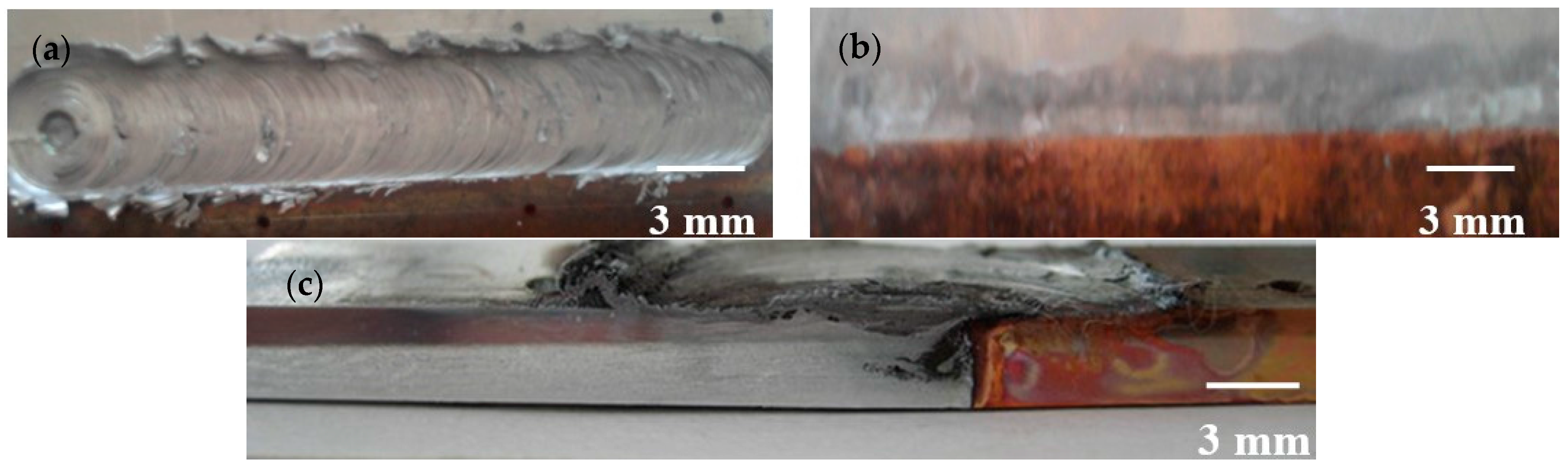
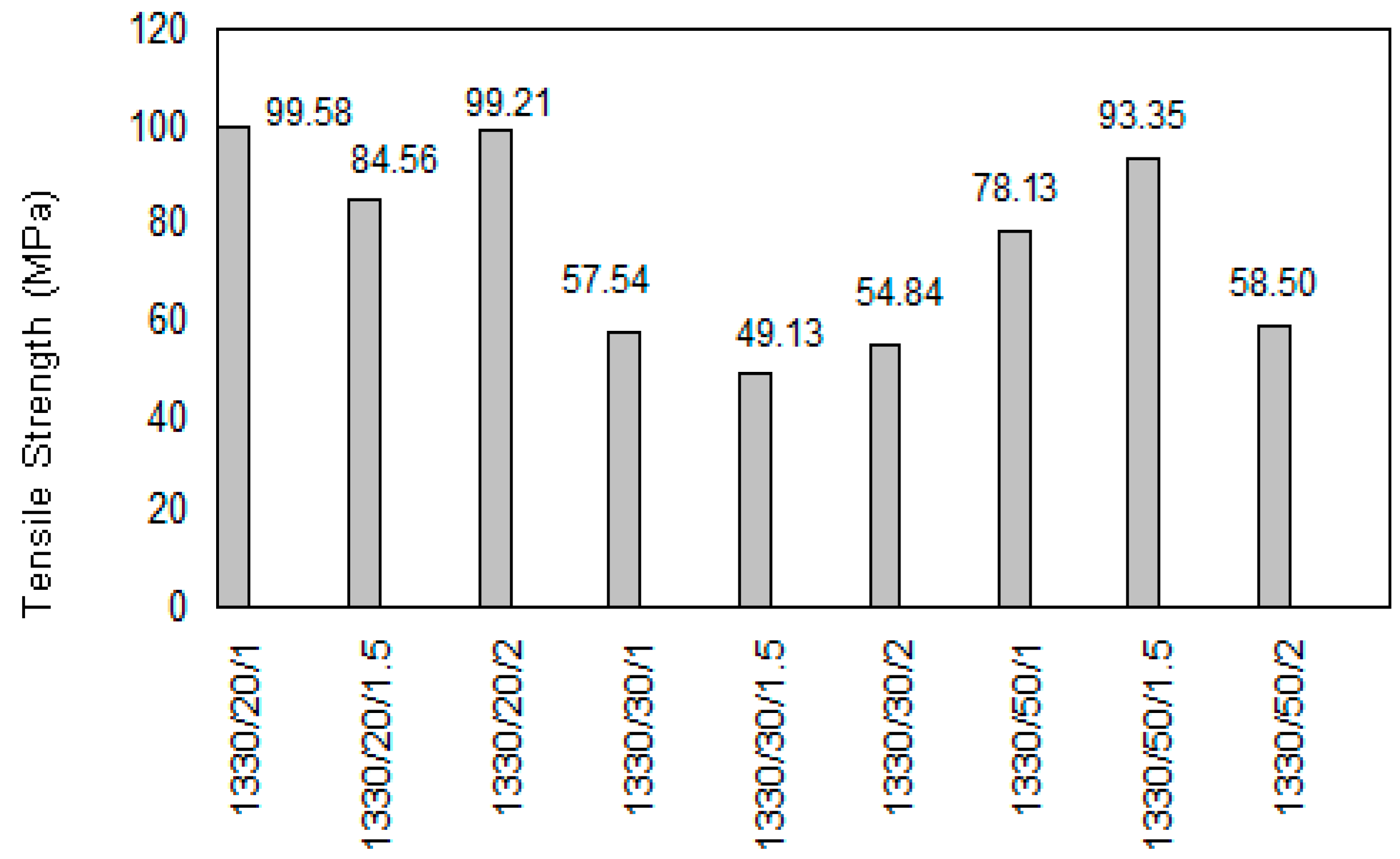
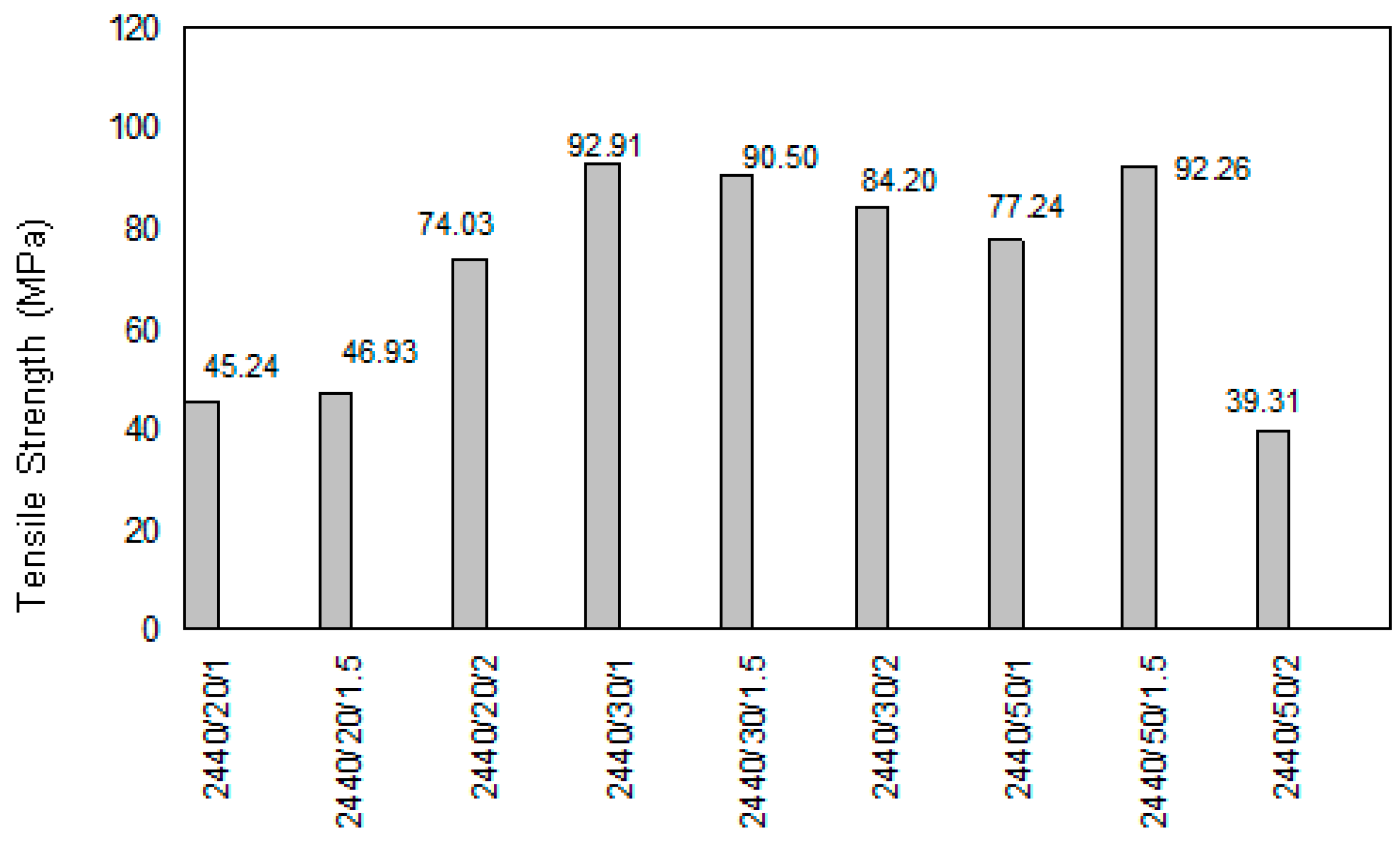
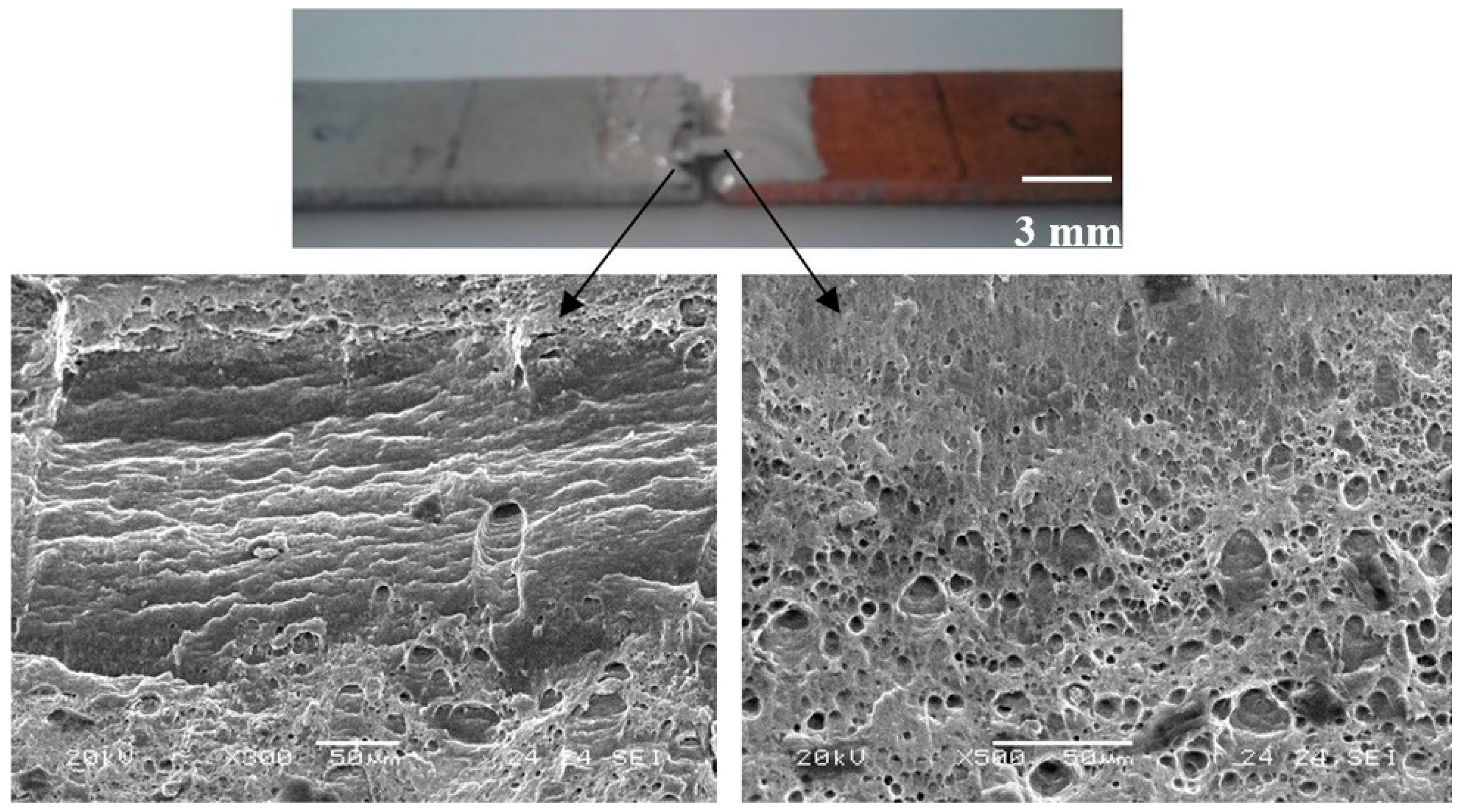
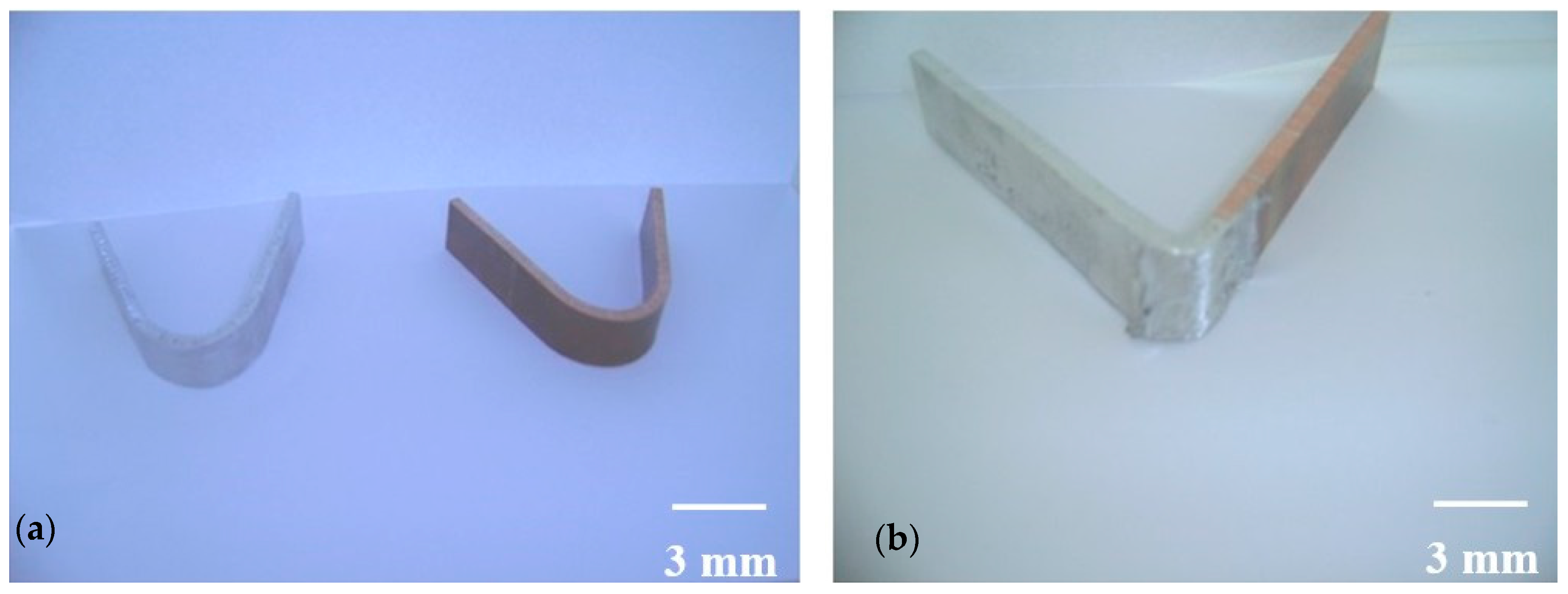
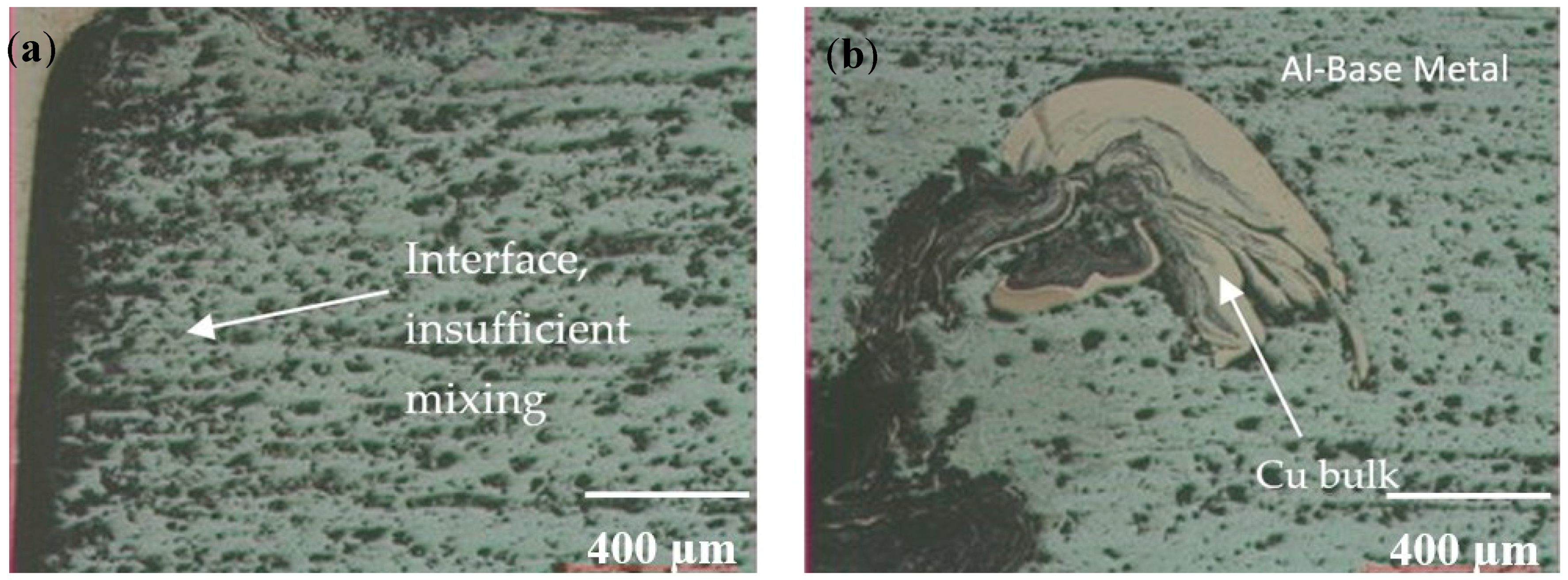
  • In this study, the friction stir butt weldability of pure Cu and 1050 Al alloy was examined, and it was successfully accomplished under different parameters by using a cylindrical pin tool. Failures were observed in the weldings that has none tool shifting (zero positioned tool). Macro-level welding defects were not observed on the welded surfaces in the case of joints for which the stir pin was positioned at 1, 1.5 and 2 mm to the Al side. However, micro-level gaps were observed in low tensile strength specimens.
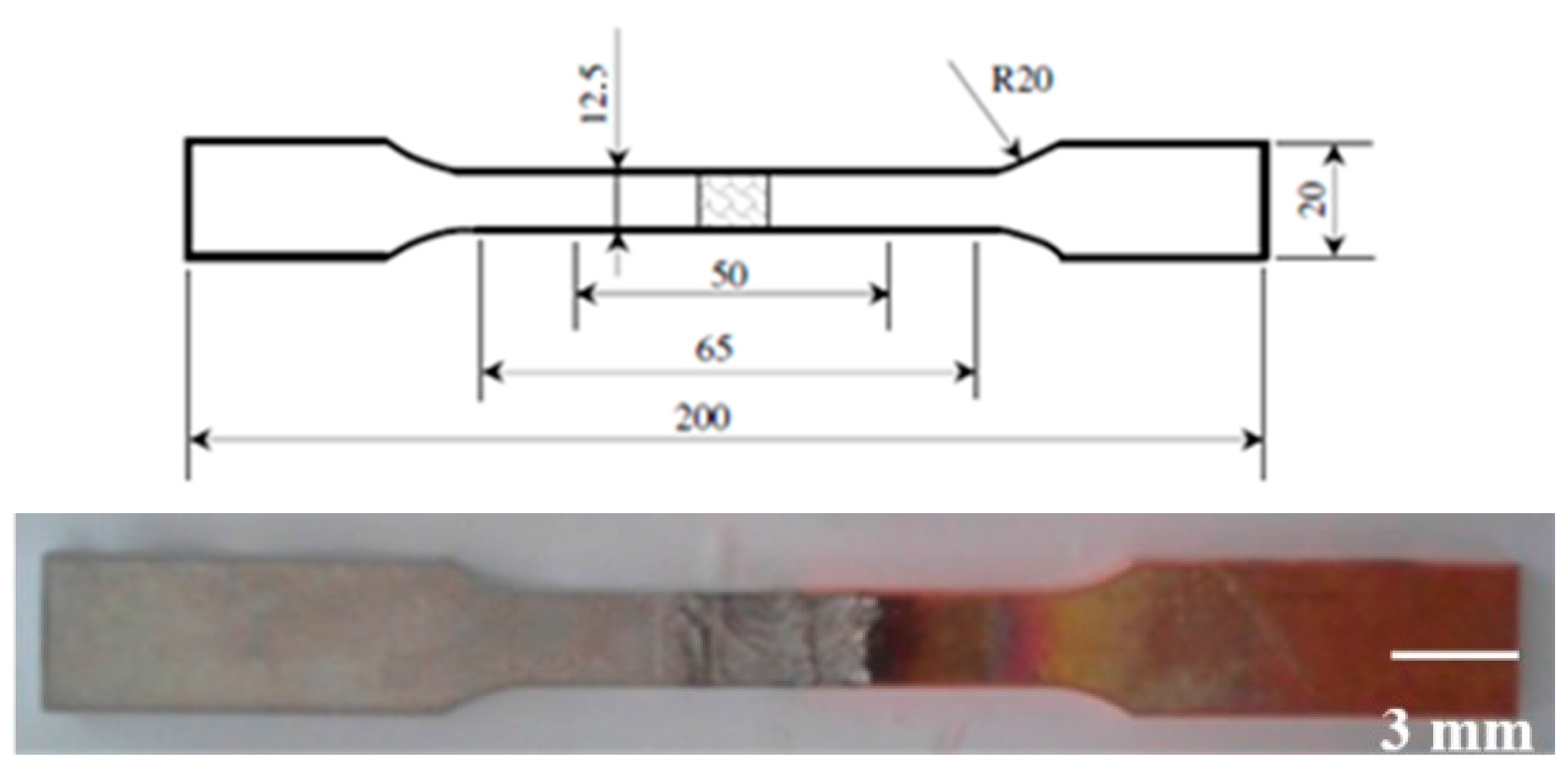
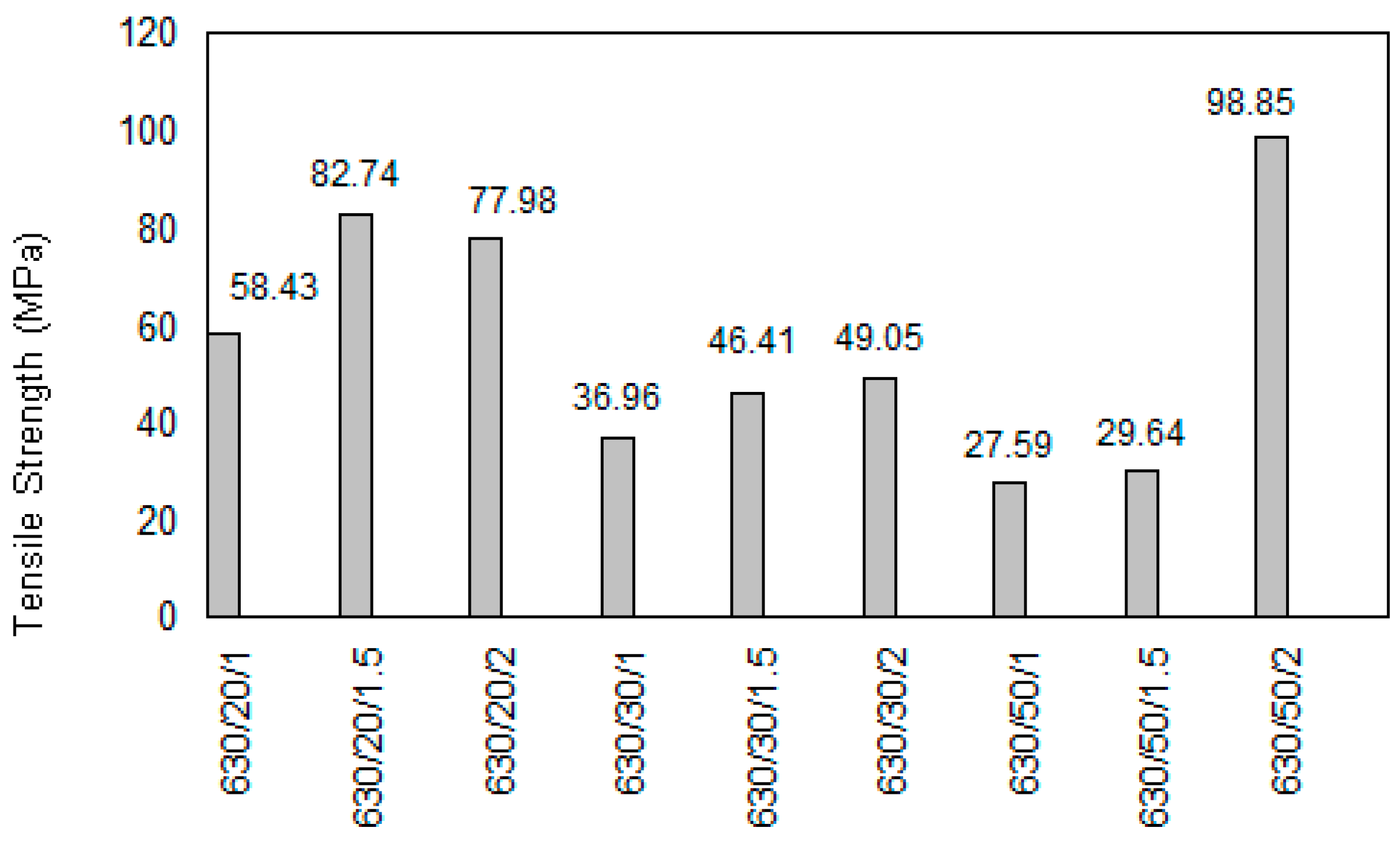
  • Tensile and bending tests, as well as hardness measurements were made in order to determine the mechanical properties of joints. When the welding performance of joints was evaluated, the maximum value was found to be 89.5% with a 1330 rpm tool rotational speed, a 20 mm/min traverse speed and a 1 mm tool position configuration. As a result of the tensile test it was observed that ruptures usually occurred in joint zones and heat-affected zones of aluminum.
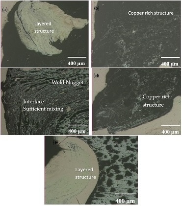
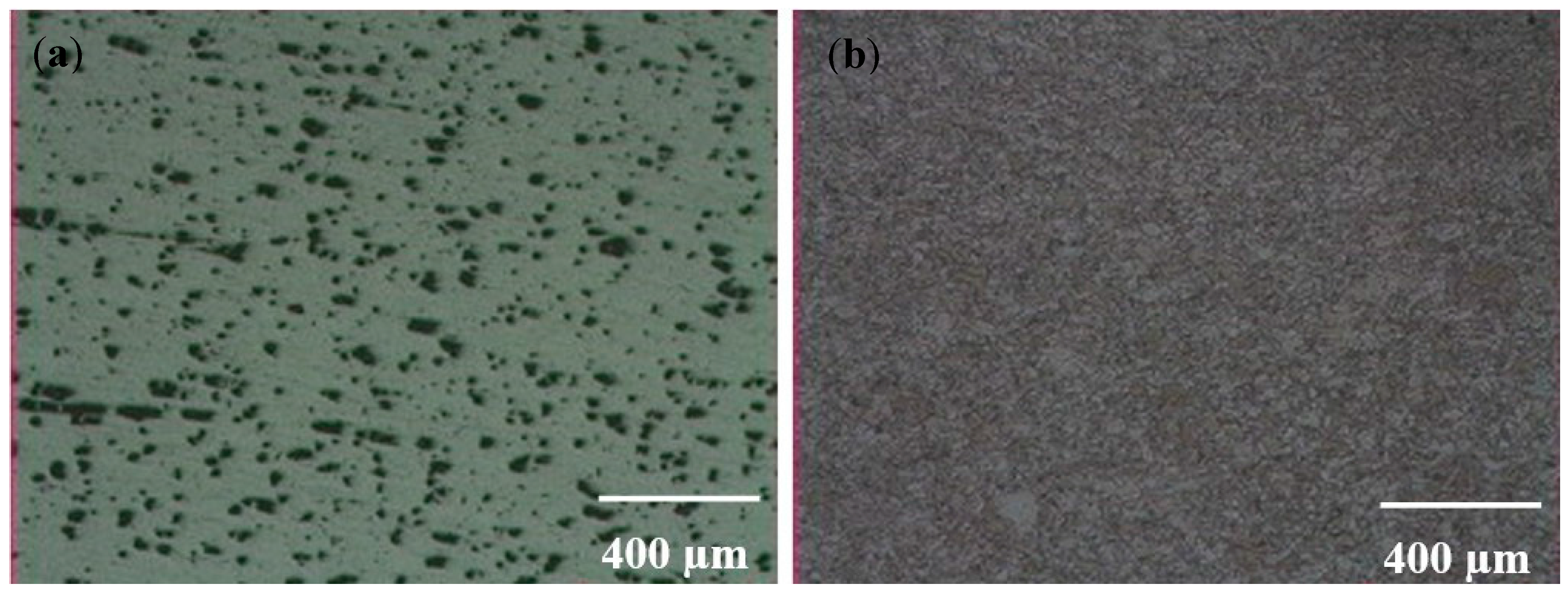
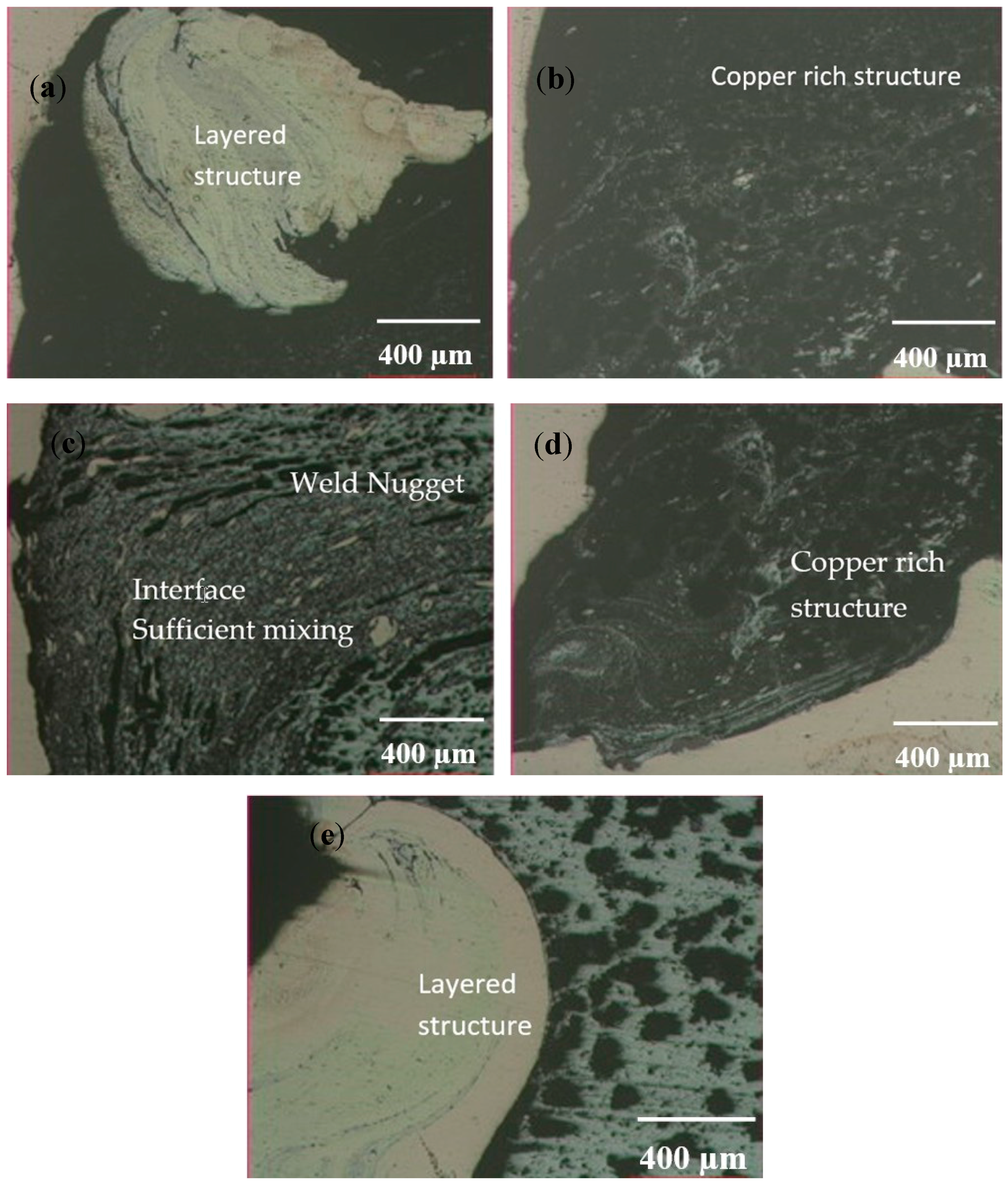
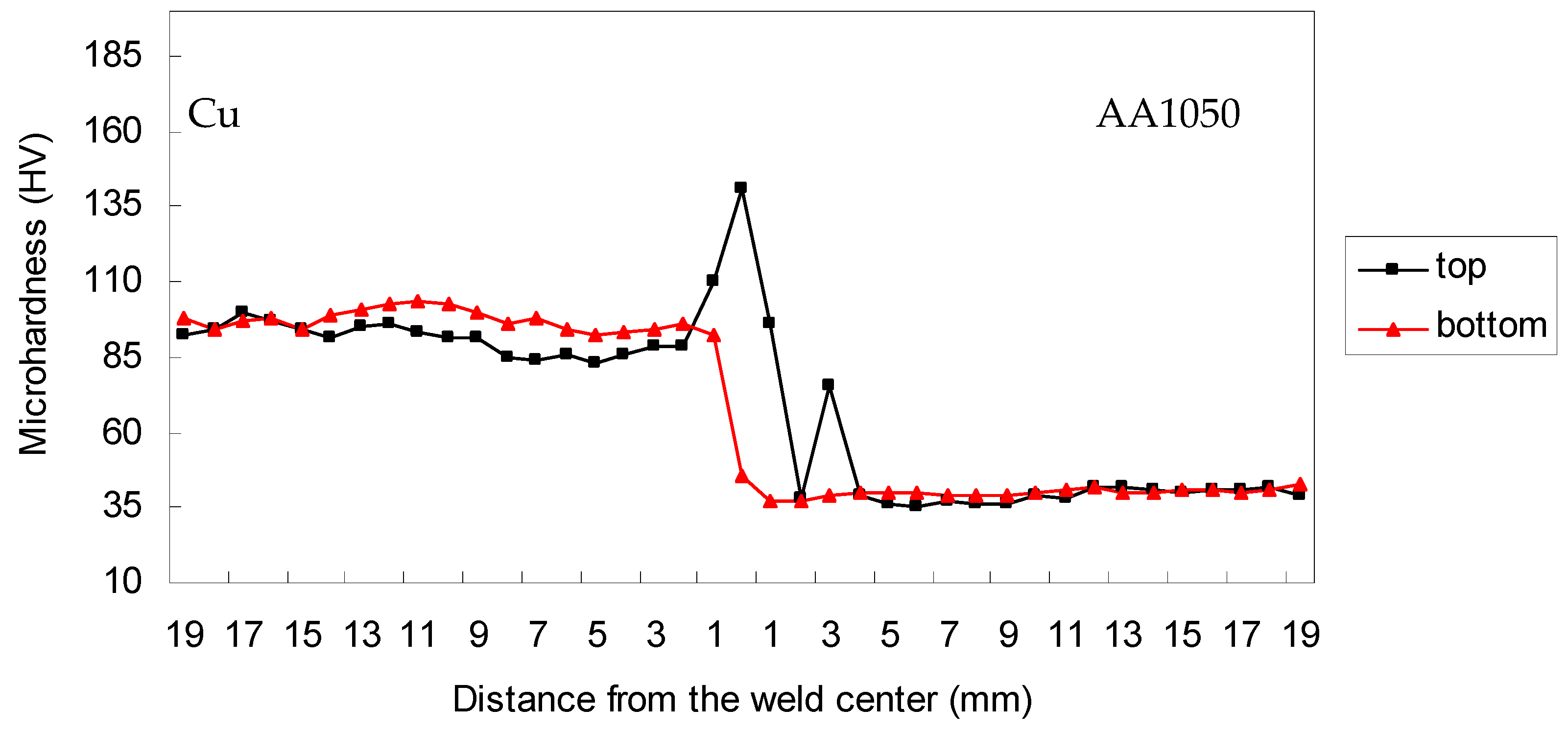
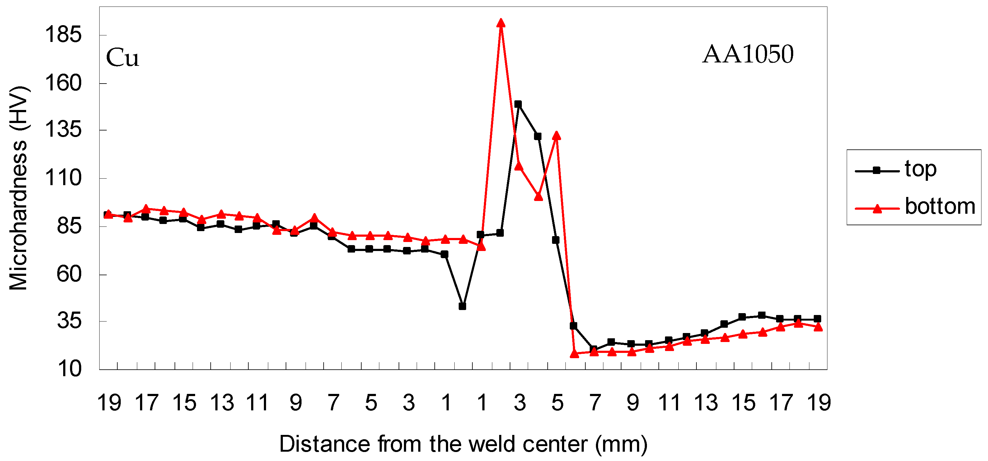
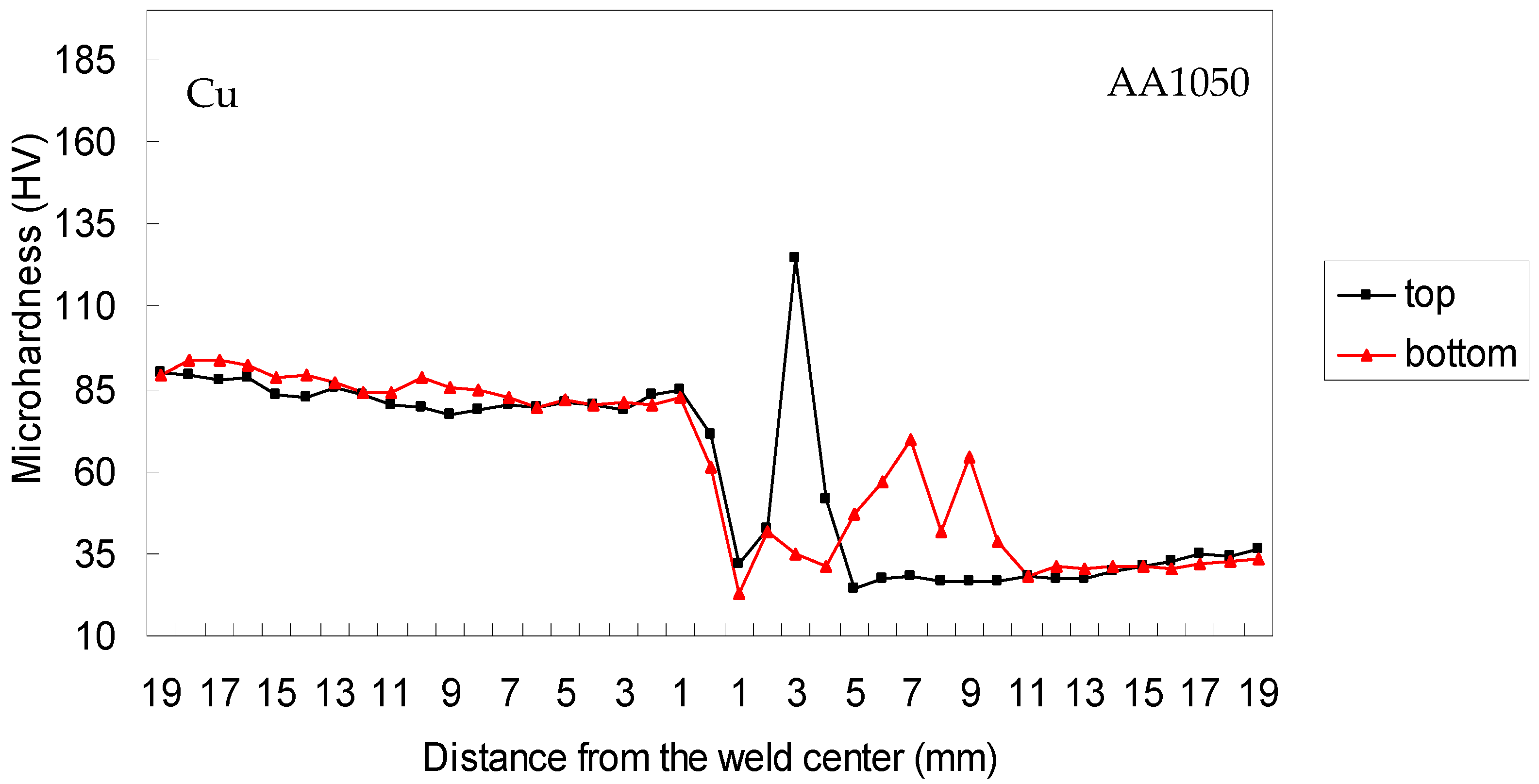
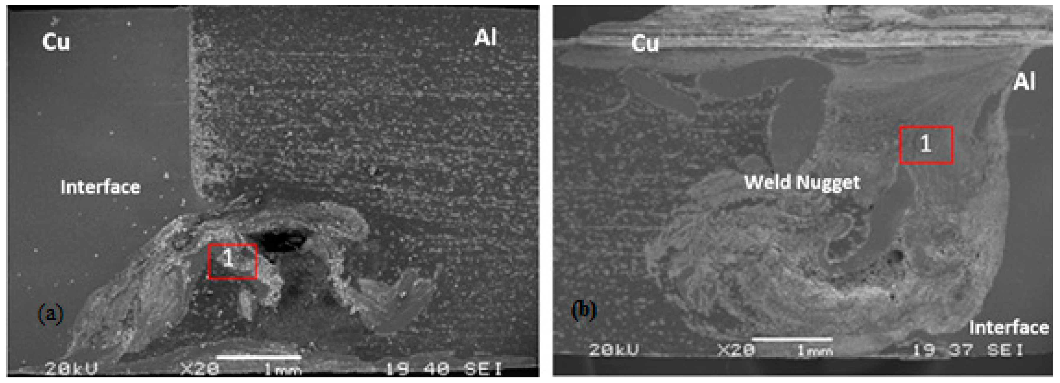
  • Due to the Al-Cu layered structure in the weld center and intermetallic phases, a hardness increase in weld zone was observed. This had the effect of mixing particles that break off from the copper in the advancing side being moved into the aluminum matrix in the retreating side. Since the weld zone was formed on the Al side, the Cu bulk in the Al matrix and intermetallic phases increased in hardness. In high tensile strength specimens, the weld zones were observed to be larger.
  • Microstructural analysis showed that the blending area happened to be on the Al side since the end of the stir pin was shifted to the Al side in proper values (1, 1.5, 2 mm). Higher strength values were obtained in a homogeneous composite structure.
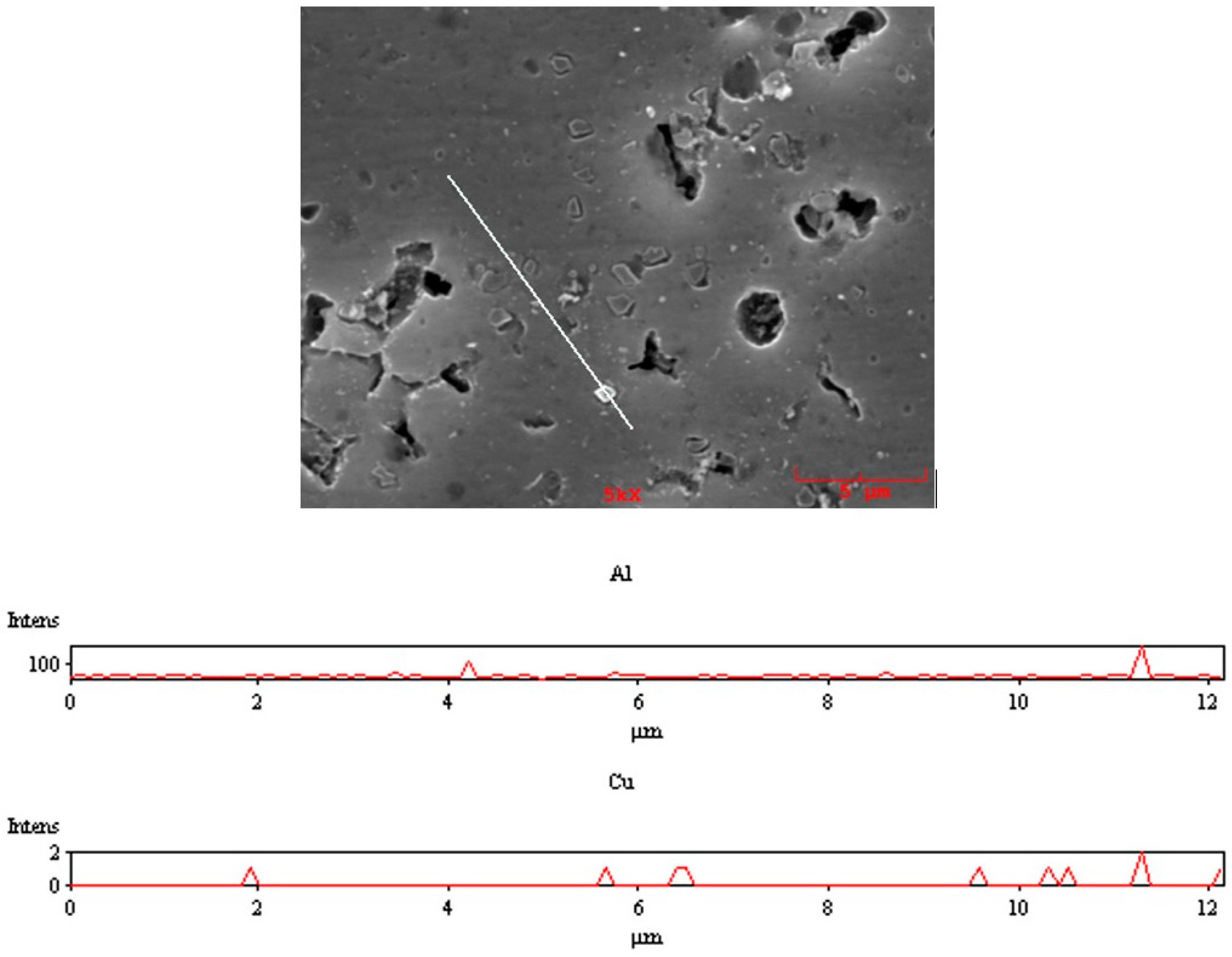
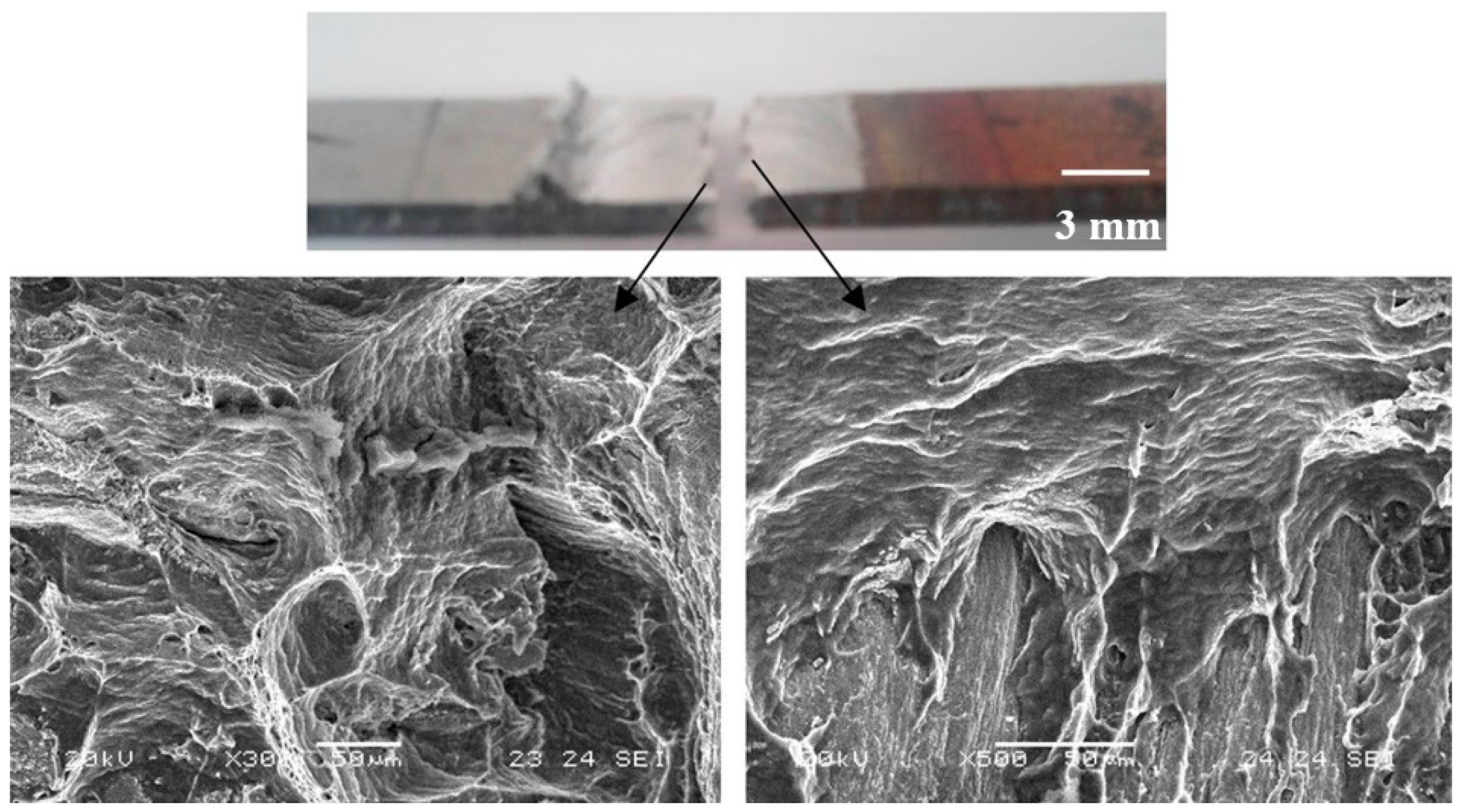
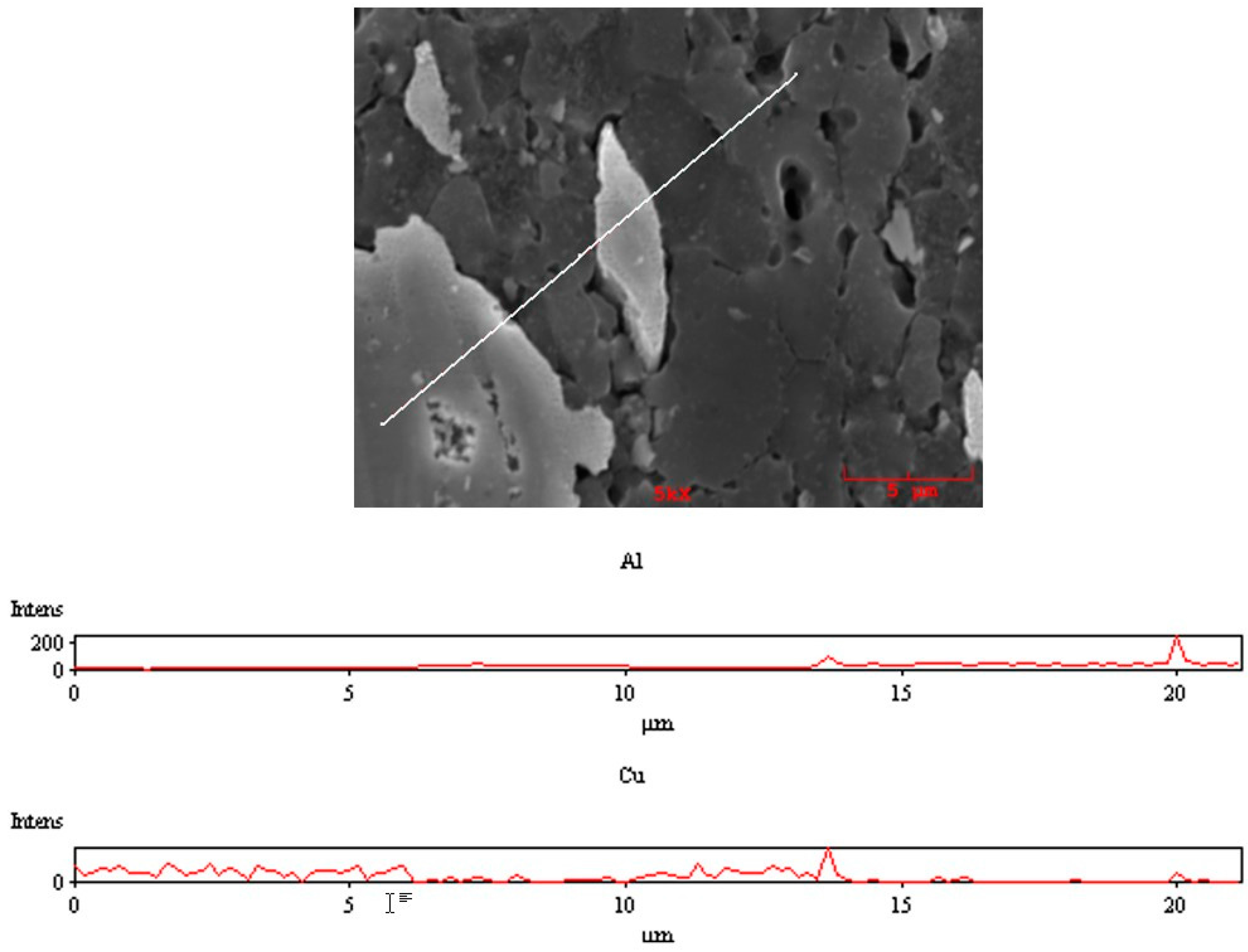
  • According to linear and point EDS analysis, Al and Cu were detected on the cross sections and fracture surfaces of joints that were obtained after tensile tests. It was observed that the Cu content in the weld zones was less in specimens with a low tensile strength compared to high tensile strength specimens.
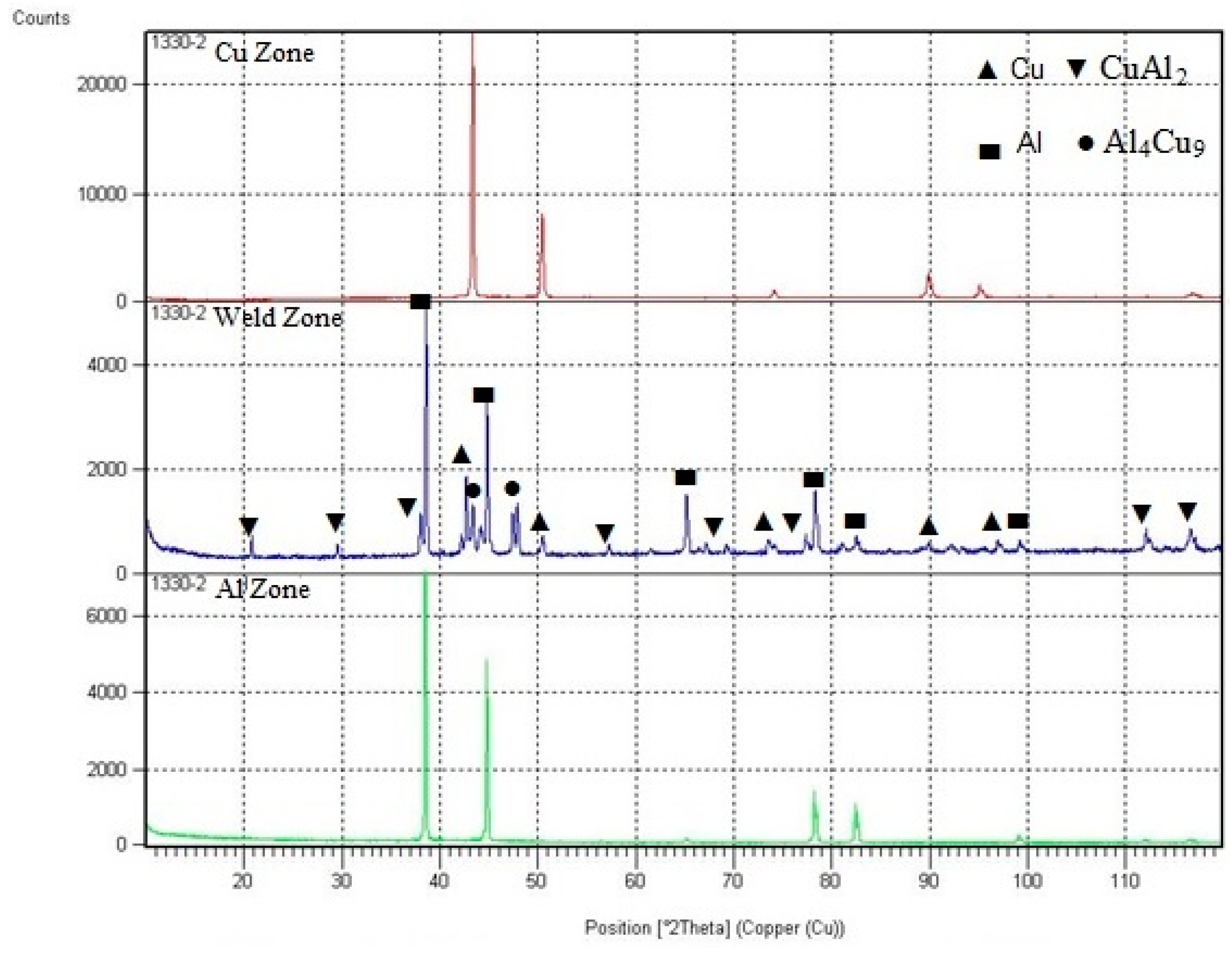
  • CuAl2 and Al4Cu9 intermetallic phases were determined in the phase analysis that was performed using X-ray diffraction (XRD). The increase of the intermetallic phase had a lowering effect on the fragility and strength.

Acknowledgments

This work was supported by the Balikesir University under Scientific Research Projects Program grant No. BAP.2012/49.

Author Contributions

S. Celik conceived, designed the experiments; R. Cakir performed the experiments under the supervision of S. Celik; both S. Celik. and R. Cakir analyzed the data; the microstructure analyses were performed in TUBITAK of Gebze Office (The Scientific and Technological Research Council of Turkey). S. Celik wrote the paper.

Conflicts of Interest

The authors declare no conflict of interest.

Abbreviations

The following abbreviations are used in this manuscript:
FSWFriction Stir Welding
EDSEnergy Dispersed Spectrometer
SEMScanning Electron Microscope
XRDX-ray Diffractometer
IMCsIntermetallic Compounds
HAZHeat Affected Zone

References

  1. Thomas, W.M.; Nicholas, E.D.; Needham, J.C.; Murch, M.G.; TempleSmith, P.; Dawes, C.J. International Patent Application No. PCT/GB92/02203 and GB Patent Application No. 9125978.8, 6 December 1991.
  2. Lee, W.B.; Jung, S.B. The joint properties of copper by friction stir welding. Mater. Lett. 2004, 58, 1041–1046. [Google Scholar] [CrossRef]
  3. Jata, K.V.; Semiatin, S.L. Continuous Dynamic Recrystallization during Friction Stir Welding of High Strength Aluminum Alloys. Scr. Mater. 2000, 43, 743–749. [Google Scholar] [CrossRef]
  4. Hwang, Y.M.; Fan, P.L.; Lin, C.H. Experimental study on Friction Stir Welding of copper metals. J. Mater. Process. Technol. 2010, 210, 1667–1672. [Google Scholar] [CrossRef]
  5. Muthu, M.F.X.; Jayabalan, V. Tool travel speed effects on the microstructure of friction stir welded aluminum–copper joints. J. Mater. Process. Technol. 2015, 217, 105–113. [Google Scholar] [CrossRef]
  6. Abdollah-Zadeh, A.; Saeid, T.; Sazgari, B. Microstructural and mechanical properties of friction stir welded aluminum/copper lap joints. J. Alloy. Compd. 2008, 460, 535–538. [Google Scholar] [CrossRef]
  7. Mubiayi, M.P.; Akinlabi, E.T. Friction Stir Welding of Dissimilar Materials between Aluminium Alloys and Copper—An Overview. In Proceedings of the World Congress on Engineering 2013 Vol III, WCE 2013, London, UK, 3–5 July 2013.
  8. Galvão, I.; Verdera, D.; Gesto, D.; Loureiro, A.; Rodrigues, D.M. Influence of aluminium alloy type on dissimilar friction stir lap welding of aluminium to copper. J. Mater. Process. Technol. 2013, 213, 1920–1928. [Google Scholar] [CrossRef] [Green Version]
  9. Saeid, T.; Abdollah-zadeh, A.; Sazgari, B. Weldability and mechanical properties of dissimilar aluminum-copper lap joints made by friction stir welding. J. Alloy. Compd. 2010, 490, 652–655. [Google Scholar] [CrossRef]
  10. Scialpi, A.; de Filippis, L.A.C.; Cavaliere, P. Influence of shoulder geometry on microstructure and mechanical properties of friction stir welded 6082 aluminium alloy. Mater. Des. 2007, 28, 1124–1129. [Google Scholar] [CrossRef]
  11. Barlas, Z.; Uzun, H. Sürtünme karıştırma kaynağı yapılmış Cu/Al-1050 alın birleştirmesinin mikroyapı ve mekanik özelliklerinin incelenmesi. Gazi Üniversity Mühendislik Mimarlik Fakkülltes Dergisi 2010, 25, 857–865. [Google Scholar]
  12. Xue, P.; Xiao, B.L.; Wang, D.; Ma, Z.Y. Achieving high property friction stir welded aluminium/copper lap joint at low heat input. Sci. Technol. Weld. Join. 2011, 16. [Google Scholar] [CrossRef]
  13. Xue, P.; Ni, D.R.; Wang, D.; Xiao, B.L.; Ma, Z.Y. Effect of friction stir welding parameters on the microstructure and mechanical properties of the dissimilar Al-Cu joints. Mater. Sci. Eng. A 2011, 528, 4683–4689. [Google Scholar] [CrossRef]
  14. Ouyang, J.; Yarrapareddy, E.; Kovacevic, R. Microstructural evolution in the friction stir welded 6061 aluminum alloy (T6-temper condition) to copper. J. Mater. Process. Technol. 2006, 172, 110–122. [Google Scholar] [CrossRef]
  15. Liu, P.; Shi, Q.; Wang, W.; Wang, X.; Zhang, Z. Microstructure and XRD analysis of FSW joints for copper T2/aluminium 5A06 dissimilar materials. Mater. Lett. 2008, 62, 4106–4108. [Google Scholar] [CrossRef]
  16. Xue, P.; Xiao, B.L.; Ni, D.R.; Ma, Z.Y. Enhanced mechanical properties of friction stir welded dissimilar Al-Cu joint by intermetallic compounds. Mater. Sci. Eng. A 2010, 527, 5723–5727. [Google Scholar] [CrossRef]
  17. Genevois, C.; Girard, M.; Huneau, B.; Sauvage, X.; Racineux, G. Interfacial Reaction during Friction Stir Welding of Al and Cu. Miner. Met. Mater. Soc. ASM Int. 2011, 42. [Google Scholar] [CrossRef]
  18. Leitão, C.; Loureiro, A.; Rodrigues, D.M. Influence of Base Material Properties and Process Parameters on Defect Formation during FSW. In Proceedings of the International Congress on Advances in Welding Science and Technology for Construction, Energy & Transportation Systems, Antalya, Turkey, 24–25 October 2011; pp. 177–184.
  19. Venkateswaran, P.; Reynolds, A.P. Factors affecting the properties of frictionstir welds between aluminum and magnesium alloys. Mater. Sci. Eng. A 2012, 545, 26–37. [Google Scholar] [CrossRef]
  20. Çelik, S. An Investigation of Diffusion Welding Parameters for Pure Aluminum and Copper in Inert Gas. Ph.D. Thesis, Balikesir University, Balikesir, Turkey, 1996. [Google Scholar]
  21. Kim, H.G.; Kim, S.M.; Lee, J.Y.; Choi, M.R.; Choe, S.C.; Kim, K.H.; Ryu, J.S.; Kim, S.; Han, S.Z.; Kim, W.Y.; et al. Microstructural evaluation of interfacial intermetallic compounds in Cu wire bonding with Al and Au pads. Acta Mater. 2014, 64, 356–366. [Google Scholar] [CrossRef]
Figure 1. Schematic representation of the fixture.
Metals 06 00133 g001
Figure 2. Weld cross section with “0” tool position.
Metals 06 00133 g002
Figure 3. Macrograph of the welded part under 630/50/1 conditions: (a) Upper surface; (b) Lower surface; (c) Cross section.
Metals 06 00133 g003
Figure 4. Welded part macro-images under 1330/20/1 condition (a) Upper surface; (b) Lower surface; (c) Cross section.
Metals 06 00133 g004
Figure 5. Dimension and macro imagine of the tensile specimen.
Metals 06 00133 g005
Figure 6. Tensile test results of 630 rpm.
Metals 06 00133 g006
Figure 7. Tensile test results of 1330 rpm.
Metals 06 00133 g007
Figure 8. Tensile test results of 2440 rpm.
Metals 06 00133 g008
Figure 9. Surface images after tensile tests and scanning electron microscope (SEM) images of ruptured surface of welded joints in the 1330/20/1 specimen.
Metals 06 00133 g009
Figure 10. Surface images after tensile tests and SEM images of ruptured surface of welded joints in the 630/50/1 specimen.
Metals 06 00133 g010
Figure 11. Bending test results of (a) base materials, (b) welded parts.
Metals 06 00133 g011
Figure 12. Hardness profile on the transverse cross section of the 630/50/1 specimen.
Metals 06 00133 g012
Figure 13. Hardness profile on the transverse cross section of the 1330/20/1 specimen.
Metals 06 00133 g013
Figure 14. Hardness profile on the transverse cross section of the 2440/30/1 specimen.
Metals 06 00133 g014
Figure 15. Microstructures of base materials: (a) Al-1050; (b) Cu.
Metals 06 00133 g015
Figure 16. Welded zone of the 630/50/1 specimen: (a) Al side; (b) Nugget Zone.
Metals 06 00133 g016
Figure 17. Welded zone of the 1330/20/1 specimen: (a) Al side top area; (b) Al side mid-area; (c) Weld Nugget; (d) Al side bottom area; (e) Al base material transition.
Metals 06 00133 g017
Figure 18. SEM images of (a) 630/50/1 specimen; (b) 1330/20/1 specimen.
Metals 06 00133 g018
Figure 19. Energy dispersed spectrometer (EDS) linear analysis (630/50/1 specimen, zone No. 1).
Metals 06 00133 g019
Figure 20. EDS linear analysis (1330/20/1 specimen, zone No. 1).
Metals 06 00133 g020
Figure 21. X-ray diffraction (XRD) graphs of base materials and weld zone.
Metals 06 00133 g021
Table 1. Mechanical properties of Al and Cu.
PropertiesAluminum (Al)Copper (Cu)
Tensile Strength (MPa)111.20231.38
Elongation (%)14.9841.03
Hardness (HV)4188
Table 2. Al-Cu Welding Parameters in Friction Stir Welding (FSW).
Tool Rotational Speed (rpm)Tool Traverse Speed (mm/min)Tool Positioning (to the Al Side (mm))
630–1330–2440201
1.5
2
301
1.5
2
501
1.5
2

