
Study on the Surface Integrity of a Thin-Walled Aluminum Alloy Structure after a Bilateral Slid Rolling Process


Abstract
:
1. Introduction
2. Materials and Methods
2.1. Experimental Materials
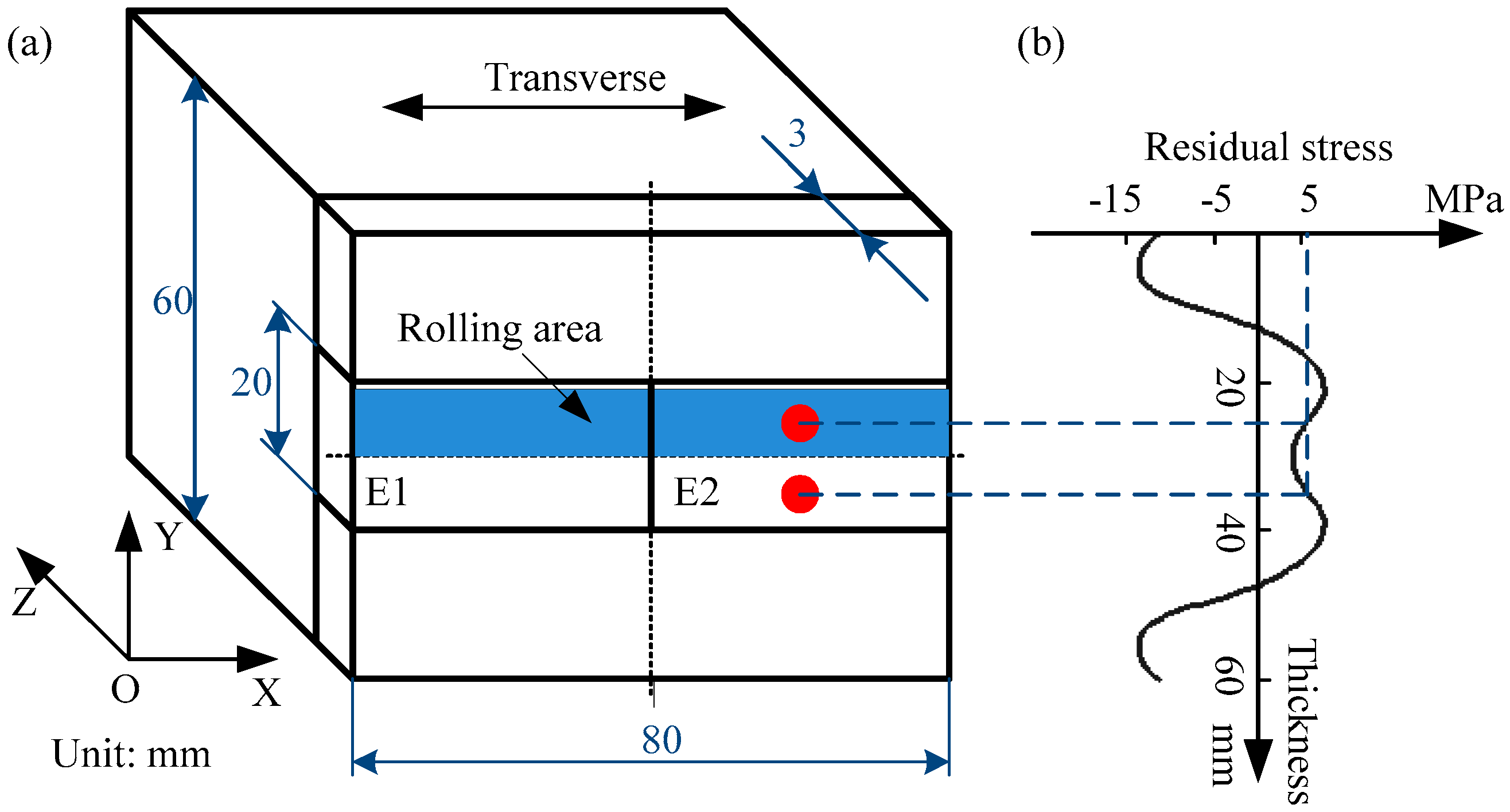
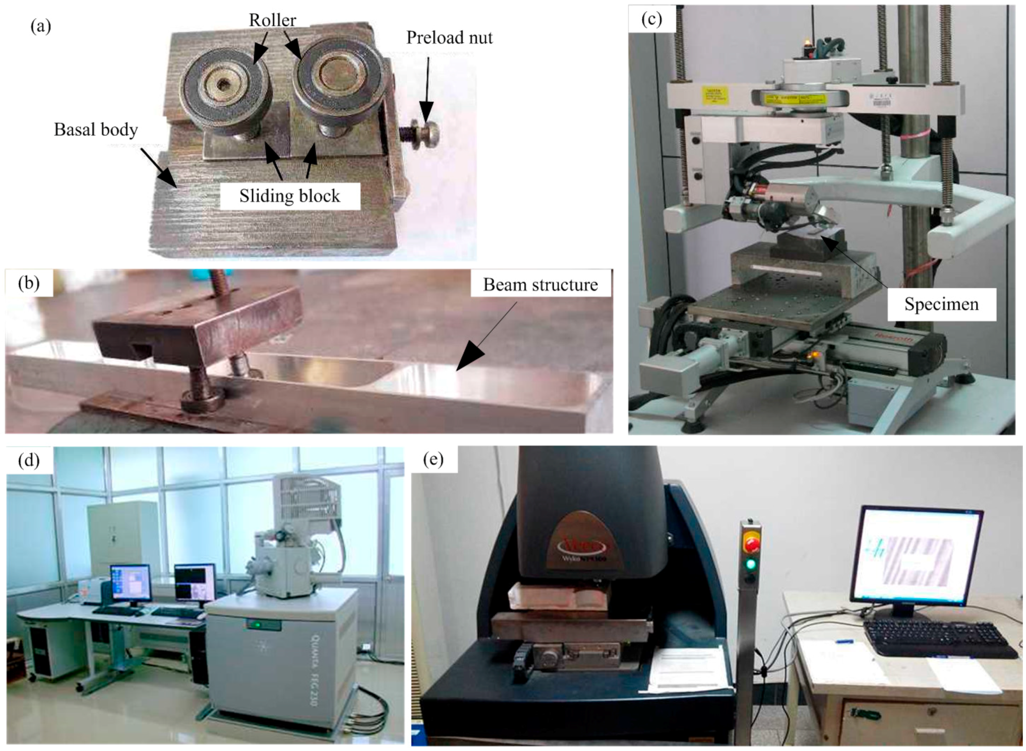
2.2. The BSRP Appliance and Experimental Design
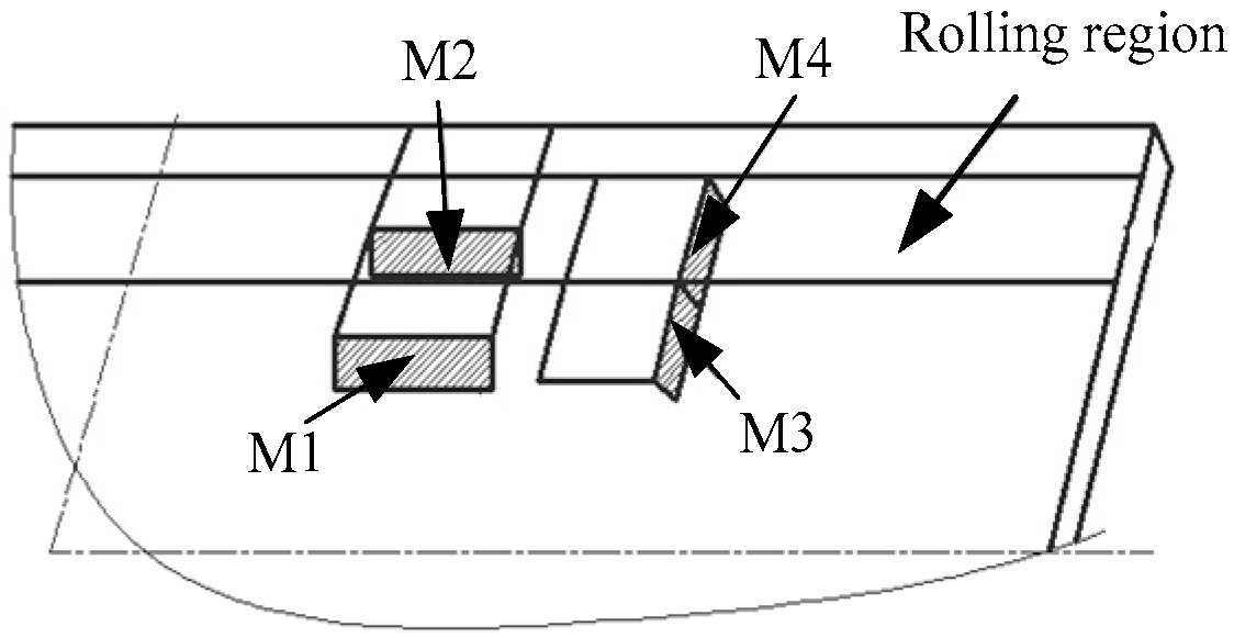
2.3. Measurement Equipment and Methods
3. Results
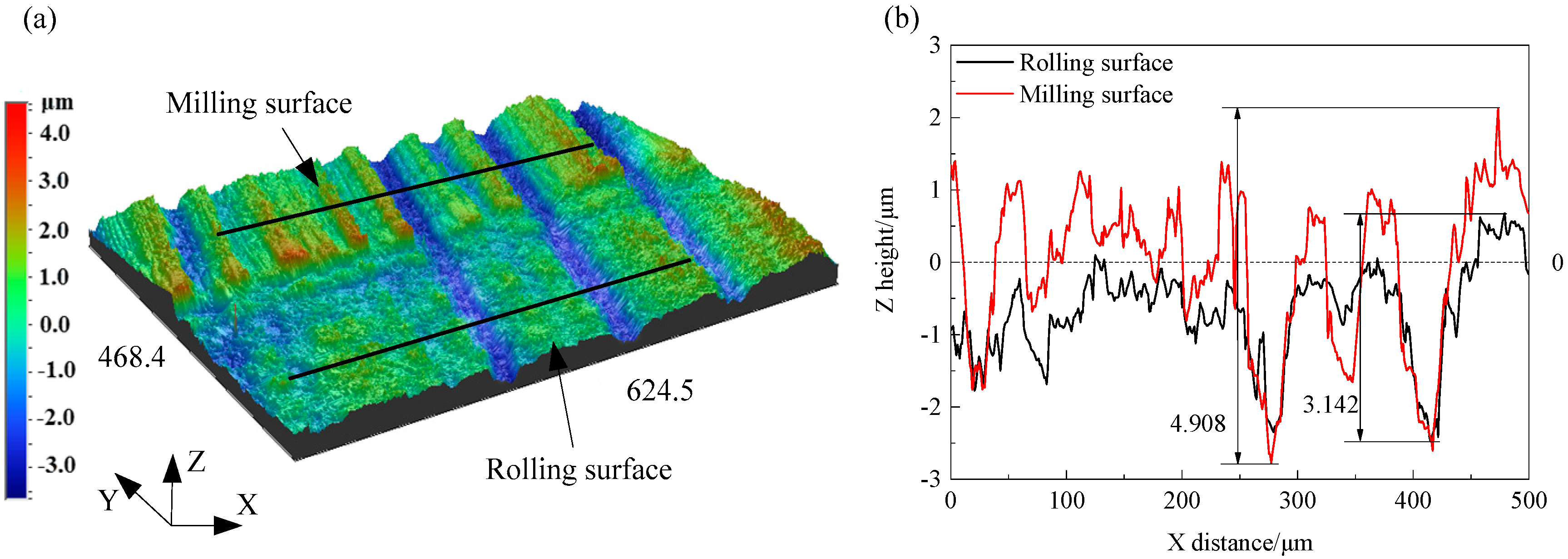
3.1. Surface Profile
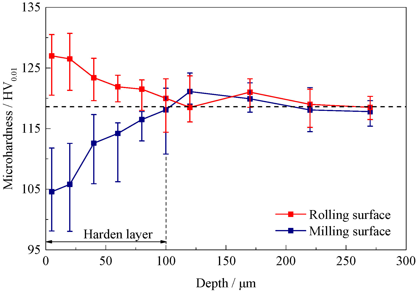
3.2. Microhardness
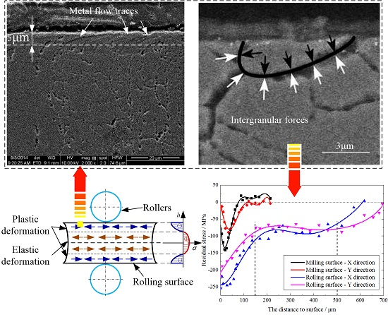
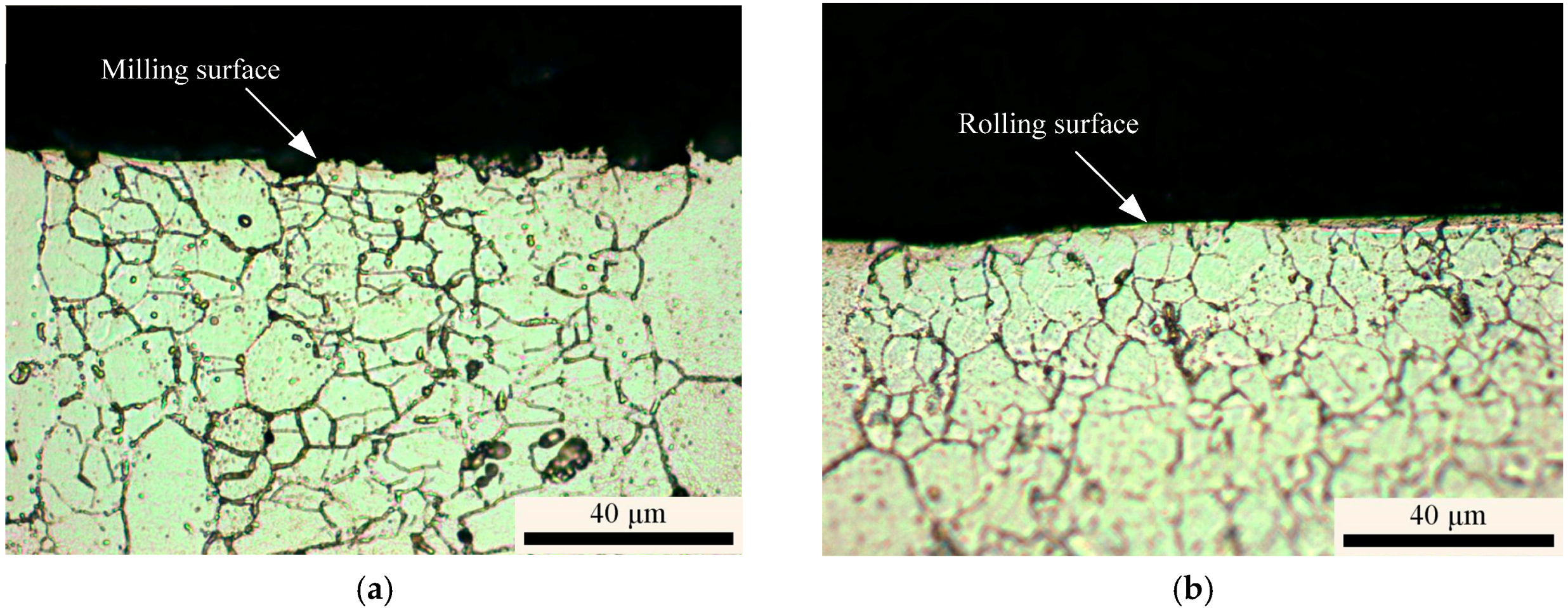
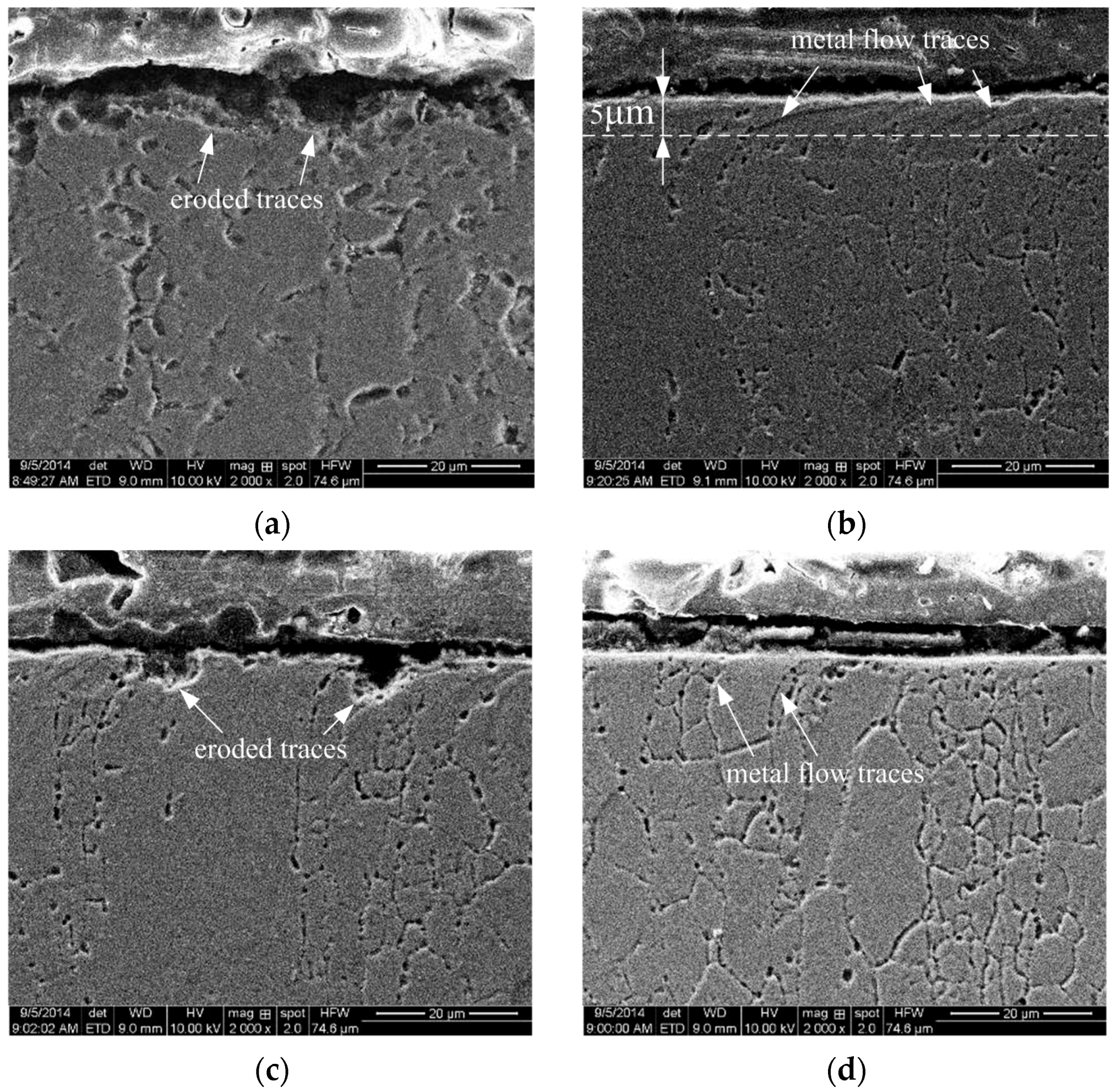
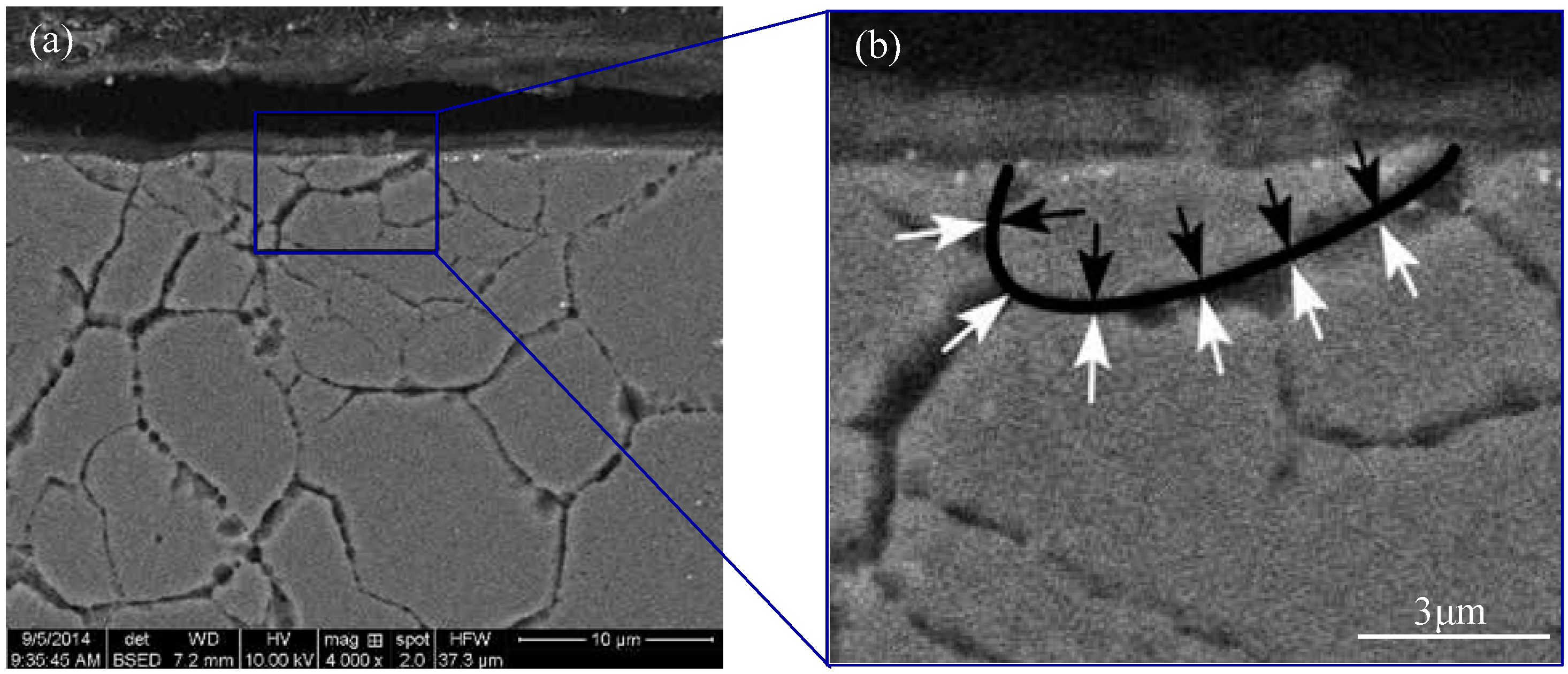
3.3. Microstructure
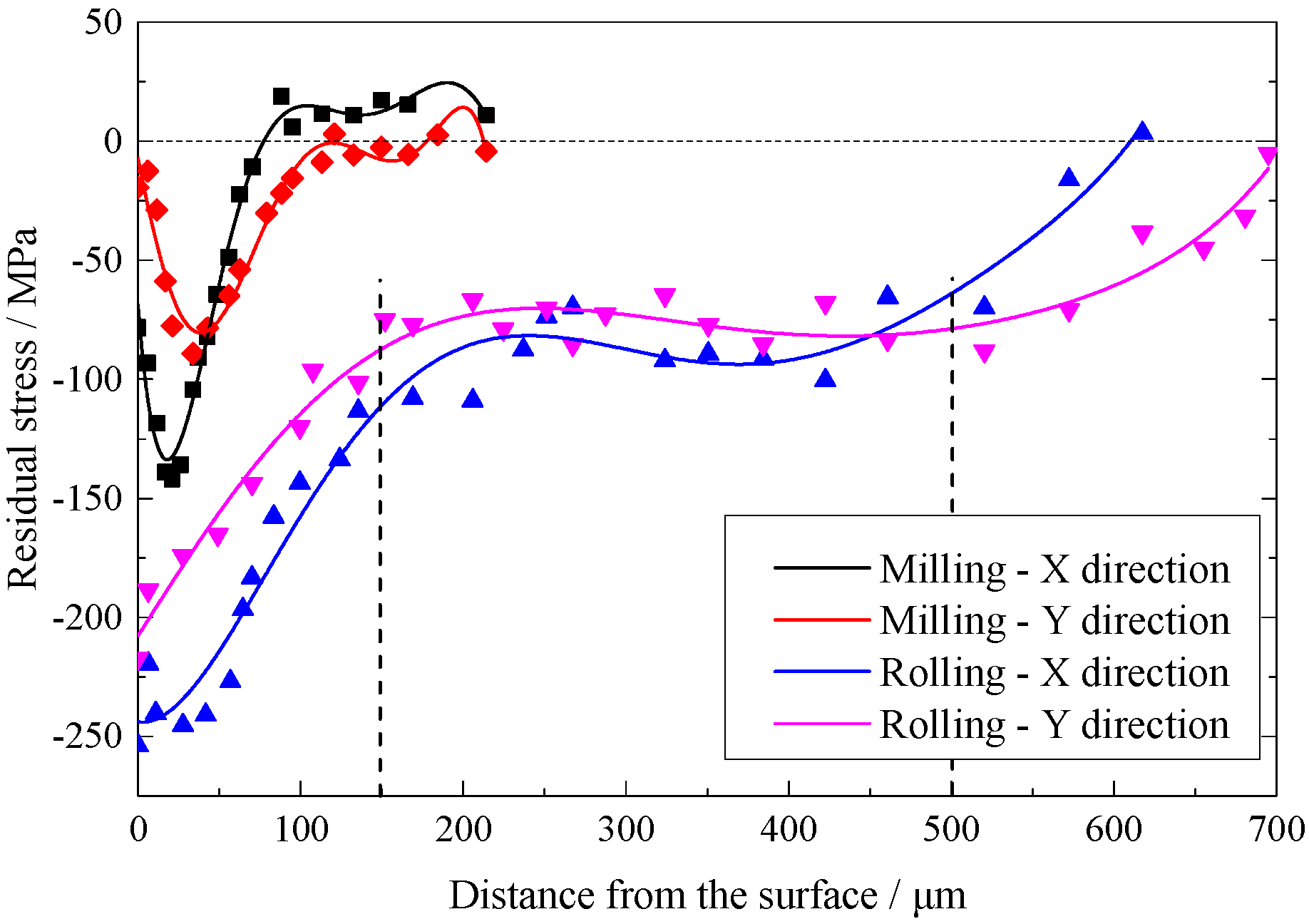
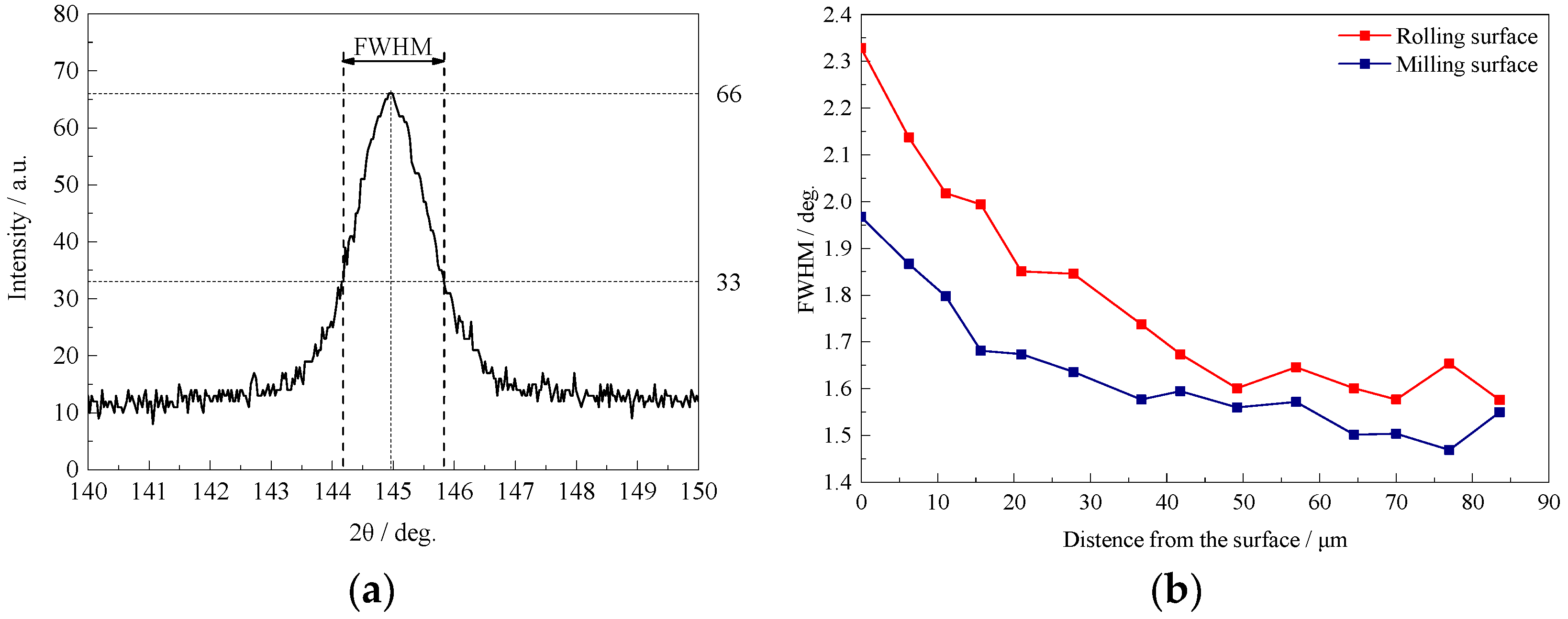
3.4. Residual Stresses
4. Discussion
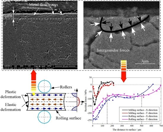
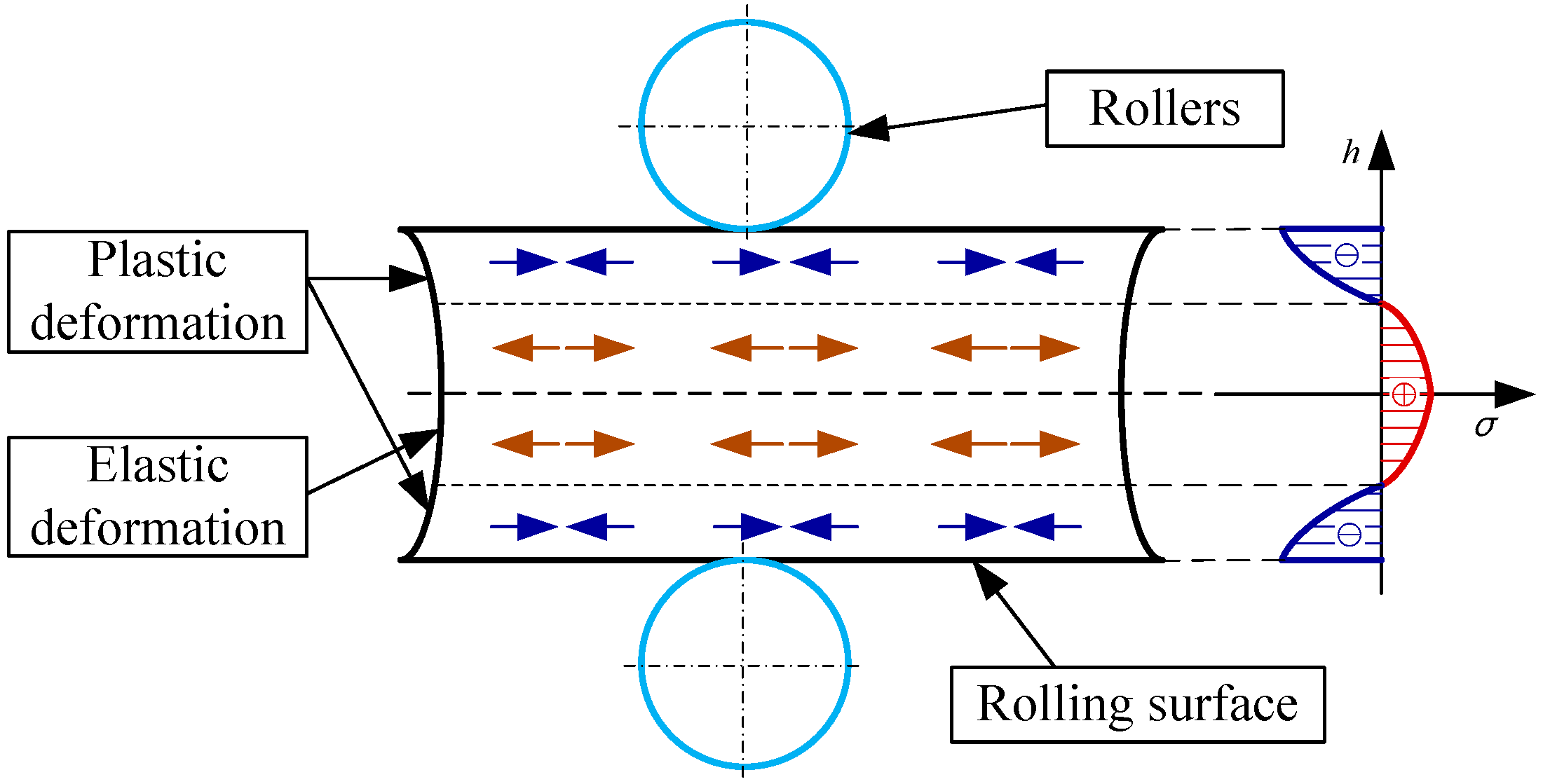
4.1. Variation Mechanisms of the Rolling Surface
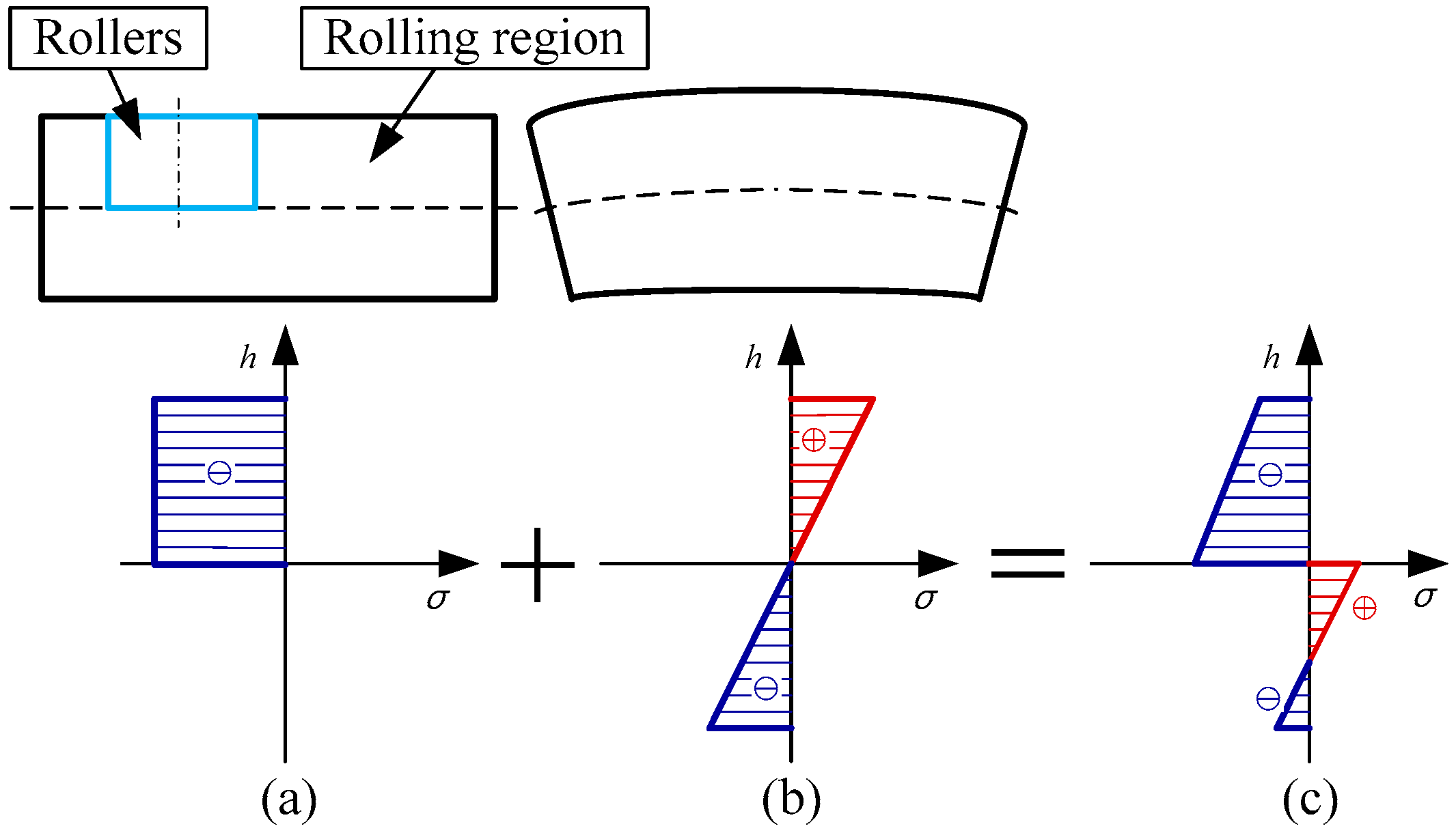
4.2. Generation Mechanism of Residual Stresses
5. Conclusions
Acknowledgments
Author Contributions
Conflicts of Interest
References
- Wang, Z.Q. Study on Theory and Approach for Correcting Aerospace Monolithic Component Due to Machining Distortion Using Rolling Method. Ph.D. Thesis, Shandong University, Jinan, China, 2009. [Google Scholar]
- Wang, Z.Q.; Li, J.F.; Sun, J.; Li, G.Y. FEM analysis of deformation correction by side-wall rolling of aircraft monolithic components. China Mech. Eng. 2009, 10, 612–616. [Google Scholar]
- Uddin, M.S.; Hall, C.; Murphy, P. Surface treatments for controlling corrosion rate of biodegradable Mg and Mg-based alloy implants. Sci. Technol. Adv. Mat. 2015. [Google Scholar] [CrossRef]
- Zhao, J.; Xia, W.; Li, F.L.; Zhou, Z.Y. Research status and developing tendency of burnishing mechanism. Tool Eng. 2010, 44, 3–8. [Google Scholar]
- Skalski, K.; Morawski, A.; Przybylski, W. Analysis of contact elastic-plastic strains during the process of burnishing. Int. J. Mech. Sci. 1995, 37, 461–472. [Google Scholar] [CrossRef]
- Altenberger, I. Deep Rolling-the past, the present and the future. In Proceedings of the 9th International Conference for Shot Peening, Paris, France, 6–9 September 2005.
- Beghini, M.; Bertini, L.; Monelli, B.D.; Santus, C.; Bandini, M. Experimental parameter sensitivity analysis of residual stresses induced by deep rolling on 7075-T6 aluminium alloy. Surf. Coat. Technol. 2014, 254, 175–186. [Google Scholar] [CrossRef]
- Avilés, R.; Albizuri, J.; Rodríguez, A.; de Lacalle, L.N.L. Influence of low-plasticity ball burnishing on the high-cycle fatigue strength of medium carbon AISI 1045 steel. Int. J. Fatigue 2013, 55, 230–244. [Google Scholar] [CrossRef]
- Wang, T.; Wang, D.; Liu, G.; Gong, B.; Song, N. Investigations on the nanocrystallization of 40Cr using ultrasonic surface rolling processing. Appl. Surf. Sci. 2008, 255, 1824–1829. [Google Scholar] [CrossRef]
- Tian, Y.; Shin, Y.C. Laser-assisted burnishing of metals. Int. J. Mach. Tool Manu. 2007, 47, 14–22. [Google Scholar] [CrossRef]
- Huang, B.; Kaynak, Y.; Sun, Y.; Jawahir, I.S. Surface layer modification by cryogenic burnishing of Al 7050-T7451 alloy and validation with FEM-based burnishing model. Procedia CIRP 2015, 31, 1–6. [Google Scholar] [CrossRef]
- Sagbas, A. Analysis and optimization of surface roughness in the ball burnishing process using response surface methodology and desirabilty function. Adv. Eng. Softw. 2011, 42, 992–998. [Google Scholar] [CrossRef]
- Yu, X.; Sun, J.; Li, S.T.; Li, J.F. Influences of burnishing process on surface quality integrity of EA4T axles and establishment of prediction model. China Surf. Eng. 2014, 27, 87–95. [Google Scholar] [CrossRef]
- Juijerm, P.; Altenberger, I. Fatigue behavior of deep rolled Al-Mg-Si-Cu alloy at elevated temperature. Scr. Mater. 2006, 55, 943–946. [Google Scholar] [CrossRef]
- Zhu, Y.L.; Li, L.; Wang, K.; Huang, Y.L. An integrated ultrasonic deep rolling and burnishing technology for anti-fatigue manufacturing. J. Mech. Eng. 2009, 45, 183–186. [Google Scholar] [CrossRef]
- Kim, W.; Kawai, K.; Koyama, H.; Miyazaki, D. Fatigue strength and residual stress of groove-rolled products. J. Mater. Process. Technol. 2007, 194, 46–51. [Google Scholar] [CrossRef]
- Rodríguez, A.; de Lacalle, L.N.L.; Celaya, A.; Lamikiz, A.; Albizuri, J. Surface improvement of shafts by the deep ball-burnishing technique. Surf. Coat. Technol. 2012, 206, 2817–2824. [Google Scholar] [CrossRef]
- Nam, Y.; Jeong, Y.; Shin, B.; Byun, J. Enhancing surface layer properties of an aircraft aluminum alloy by shot peening using response surface methodology. Mater. Des. 2015, 83, 566–576. [Google Scholar] [CrossRef]
- Nie, X.; He, W.; Zang, S.; Wang, X.; Zhao, J. Effect study and application to improve high cycle fatigue resistance of TC11 titanium alloy by laser shock peening with multiple impacts. Surf. Coat. Technol. 2014, 253, 68–75. [Google Scholar] [CrossRef]
- Hennig, W.; Feldmann, G.; Haubold, T. Shot peening method for aerofoil treatment of blisk assemblies. Proced. CIRP 2014, 13, 355–358. [Google Scholar] [CrossRef]
- Cheng, M.; Zhang, D.; Chen, H.; Qin, W. Development of ultrasonic thread root rolling technology for prolonging the fatigue performance of high strength thread. J. Mater. Process. Technol. 2014, 214, 2395–2401. [Google Scholar] [CrossRef]
- Wu, B.; Wang, P.; Pyoun, Y.; Zhang, J.; Murakami, R. Study on the fatigue properties of plasma nitriding S45C with a pre-ultrasonic nanocrystal surface modification process. Surf. Coat. Technol. 2013, 216, 191–198. [Google Scholar] [CrossRef]
- Zhao, J.; Xia, W.; Li, N.; Li, F.L. A gradient nano/micro-structured surface layer on copper induced by severe plasticity roller burnishing. Trans. Nonferr. Met. Soc. China 2014, 24, 441–448. [Google Scholar] [CrossRef]
- Li, Y.; Li, J.Y.; Liu, M.; Ren, Y.Y.; Chen, F.; Yao, G.C.; Mei, Q.S. Evolution of microstructure and property of NiTi alloy induced by cold rolling. J. Alloy. Compd. 2015, 653, 156–161. [Google Scholar] [CrossRef]


| Rotation Angles (°) | Rolling Depth (mm) |
|---|---|
| 45 | 0.03 |
| 90 | 0.08 |
| 135 | 0.11 |
| 180 | 0.13 |
| 225 | 0.15 |
| 270 | 0.17 |
© 2016 by the authors; licensee MDPI, Basel, Switzerland. This article is an open access article distributed under the terms and conditions of the Creative Commons Attribution (CC-BY) license (http://creativecommons.org/licenses/by/4.0/).
Share and Cite
Lu, L.; Sun, J.; Han, X.; Xiong, Q. Study on the Surface Integrity of a Thin-Walled Aluminum Alloy Structure after a Bilateral Slid Rolling Process. Metals 2016, 6, 99. https://doi.org/10.3390/met6050099
Lu L, Sun J, Han X, Xiong Q. Study on the Surface Integrity of a Thin-Walled Aluminum Alloy Structure after a Bilateral Slid Rolling Process. Metals. 2016; 6(5):99. https://doi.org/10.3390/met6050099
Chicago/Turabian StyleLu, Laixiao, Jie Sun, Xiong Han, and Qingchun Xiong. 2016. "Study on the Surface Integrity of a Thin-Walled Aluminum Alloy Structure after a Bilateral Slid Rolling Process" Metals 6, no. 5: 99. https://doi.org/10.3390/met6050099