
Influence of Post-Weld Heat Treatment on the Microstructure, Microhardness, and Toughness of a Weld Metal for Hot Bend

Abstract
:
1. Introduction
2. Experimental Materials and Procedure
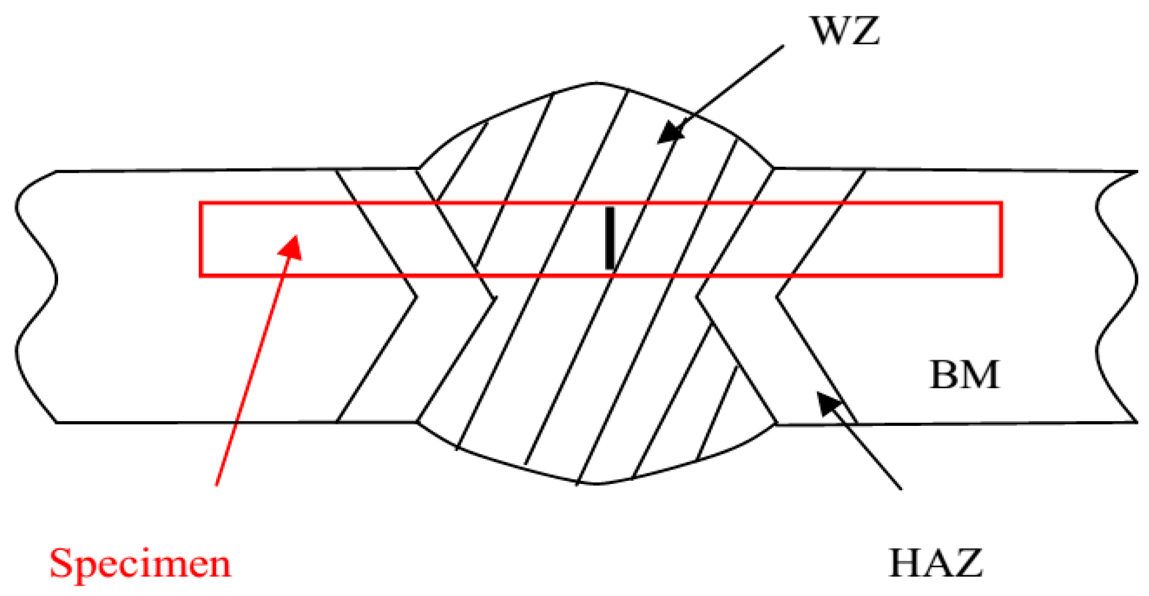
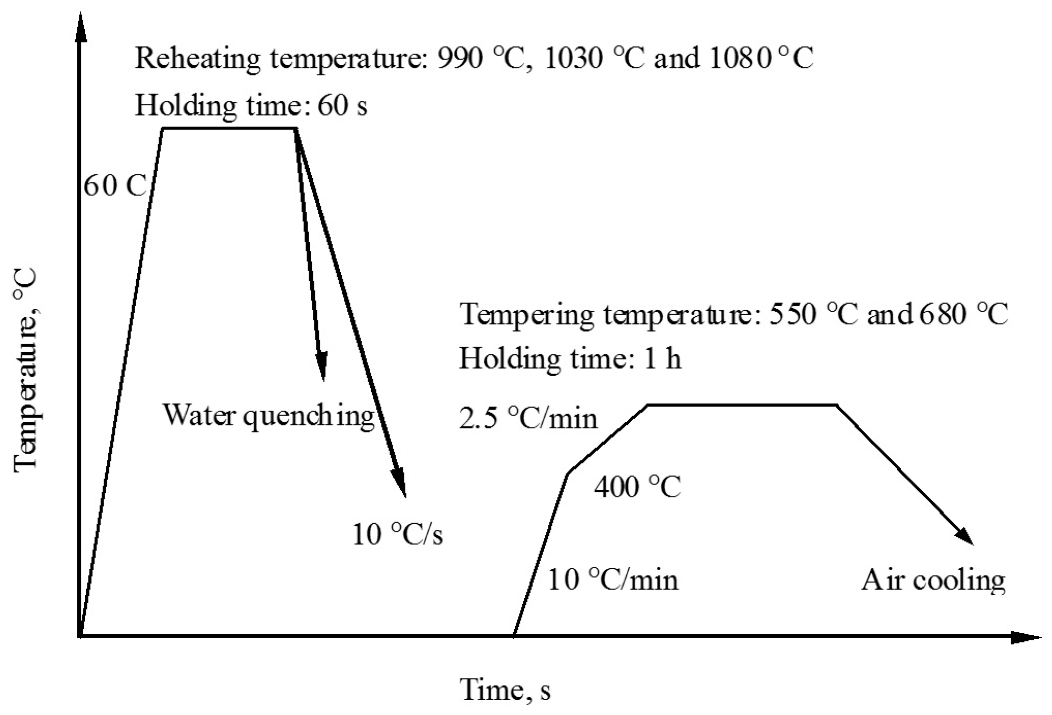
2.1. Materials and the Post-Weld Heat Treatments
2.2. Mechanical Properties
2.3. Microstructural Characterization
3. Results
3.1. Properties
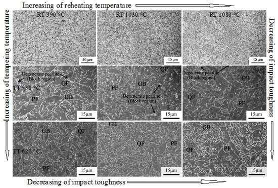
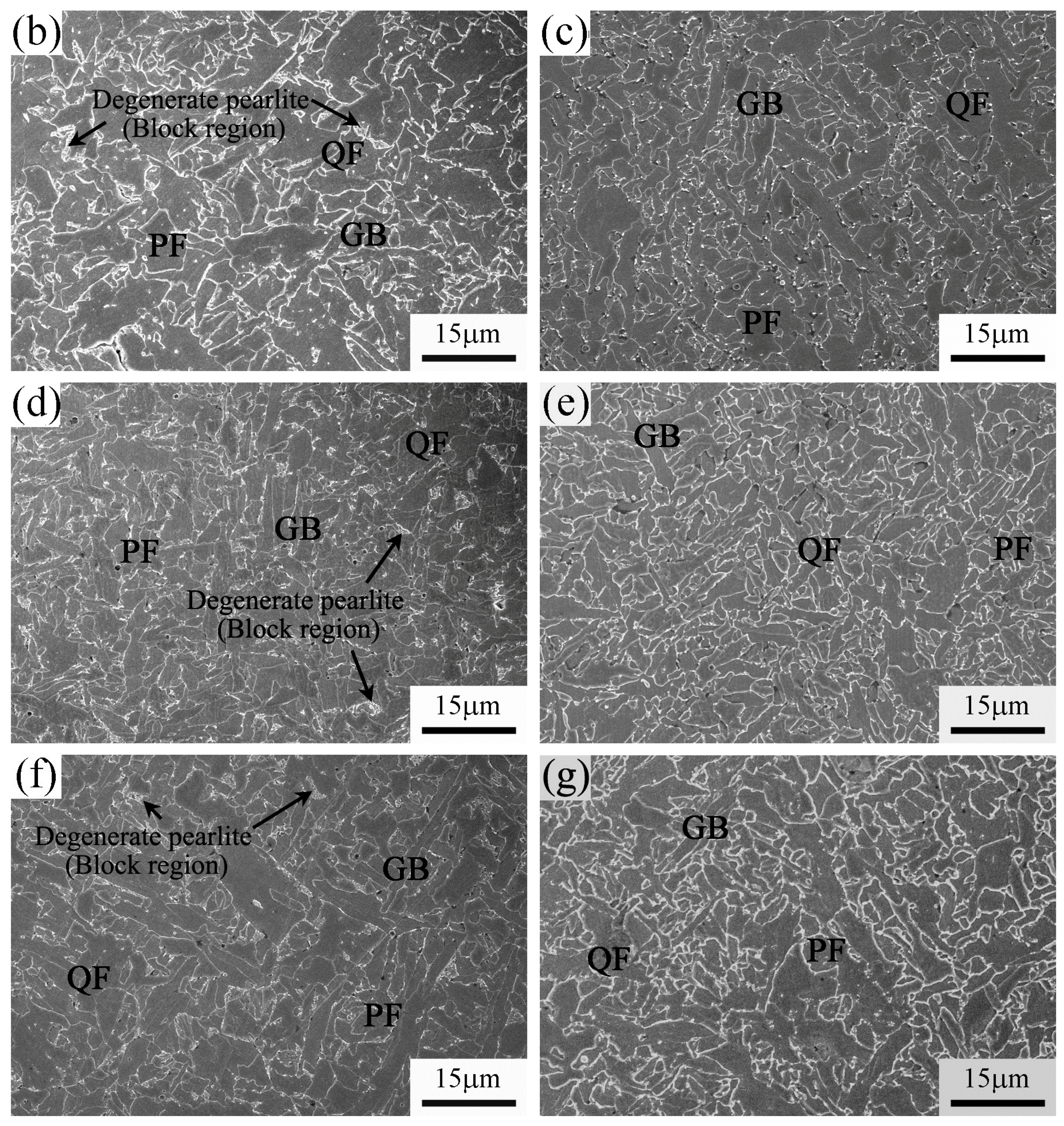
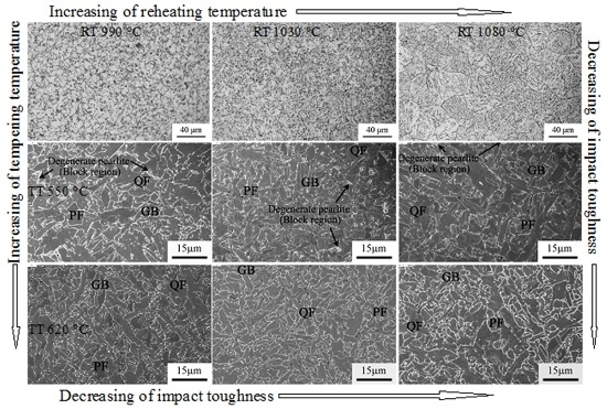
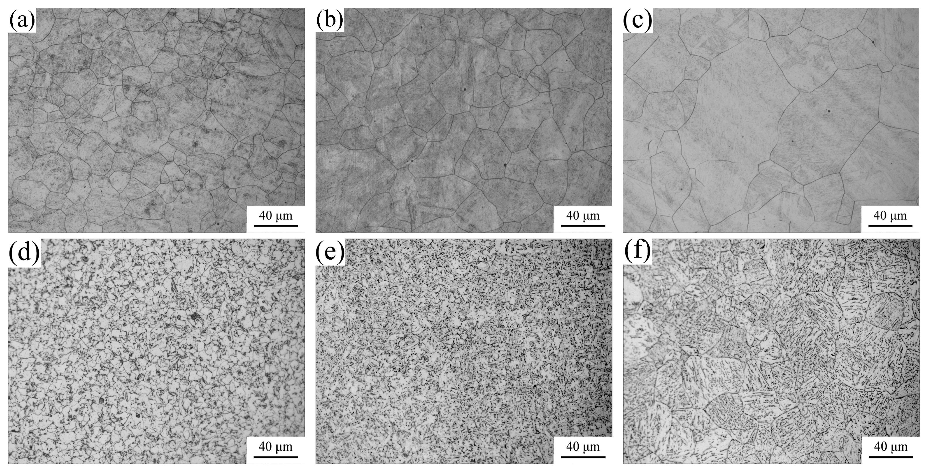
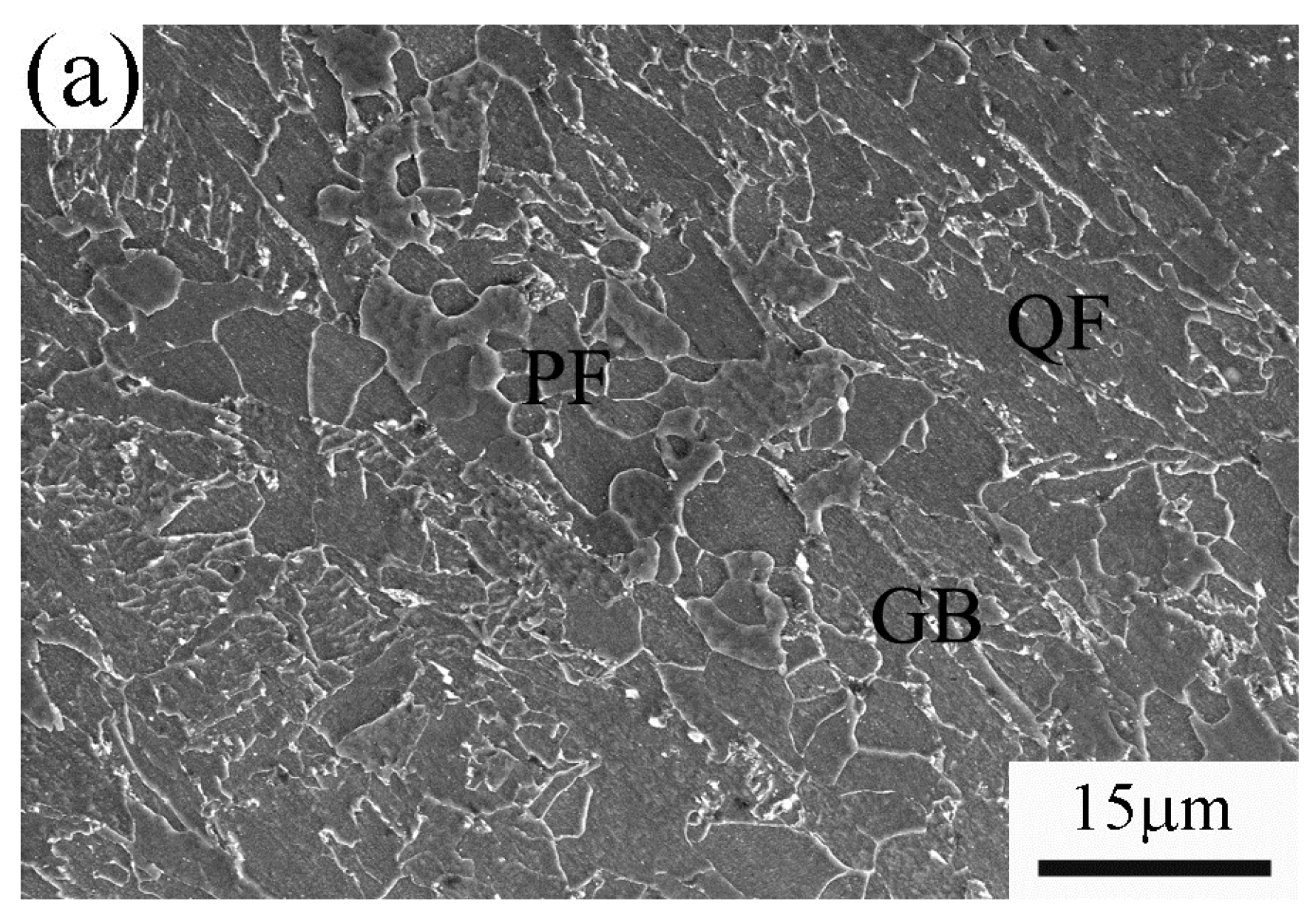
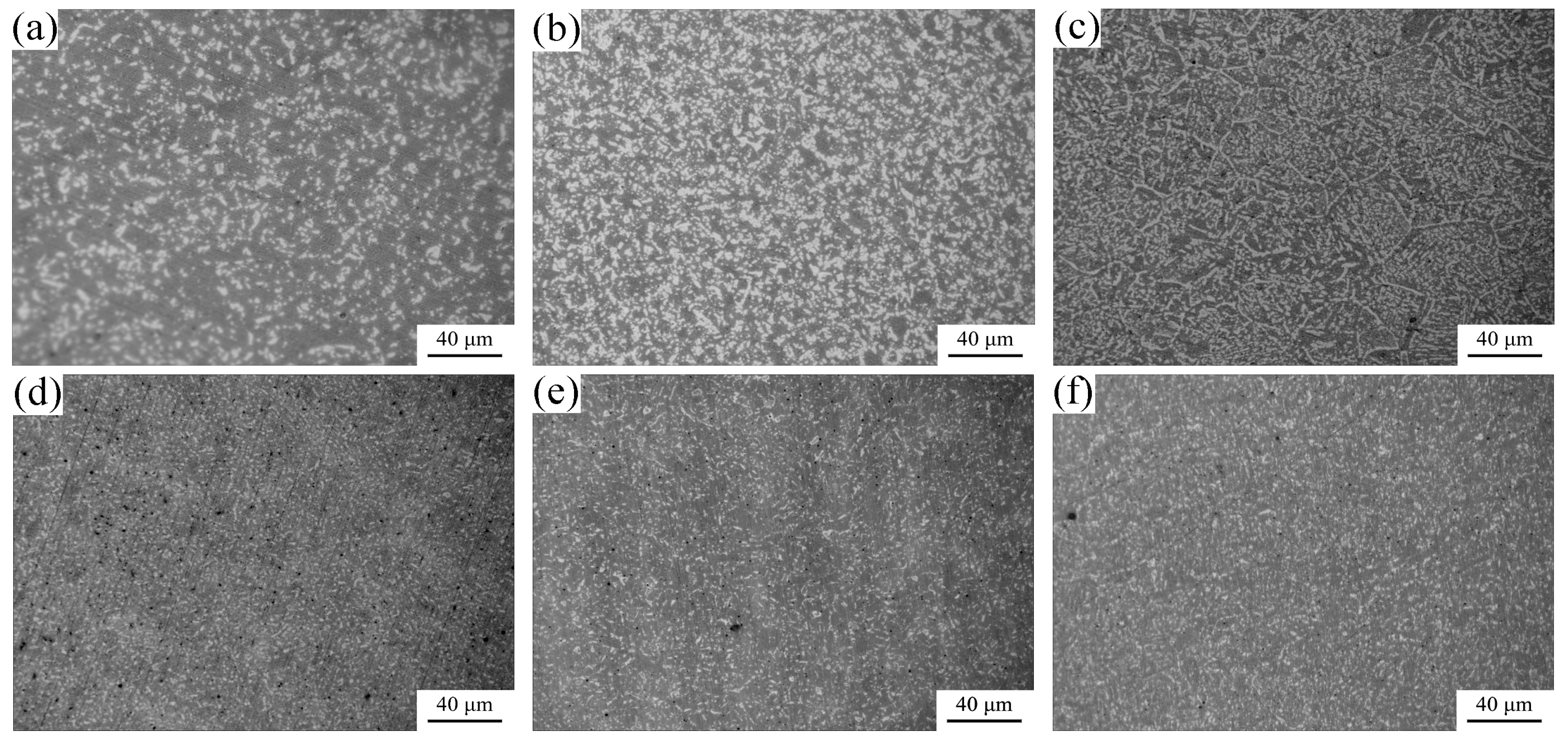
3.2. Microstructure
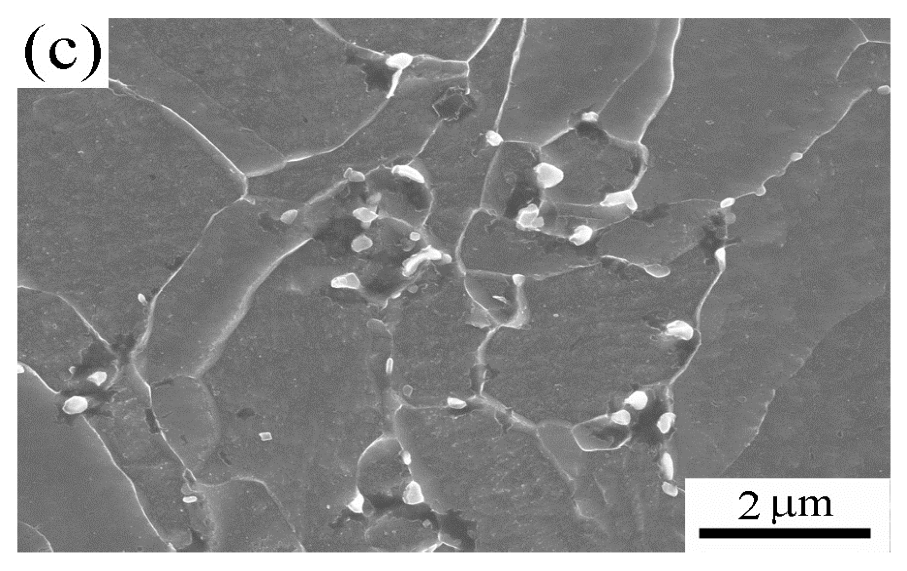
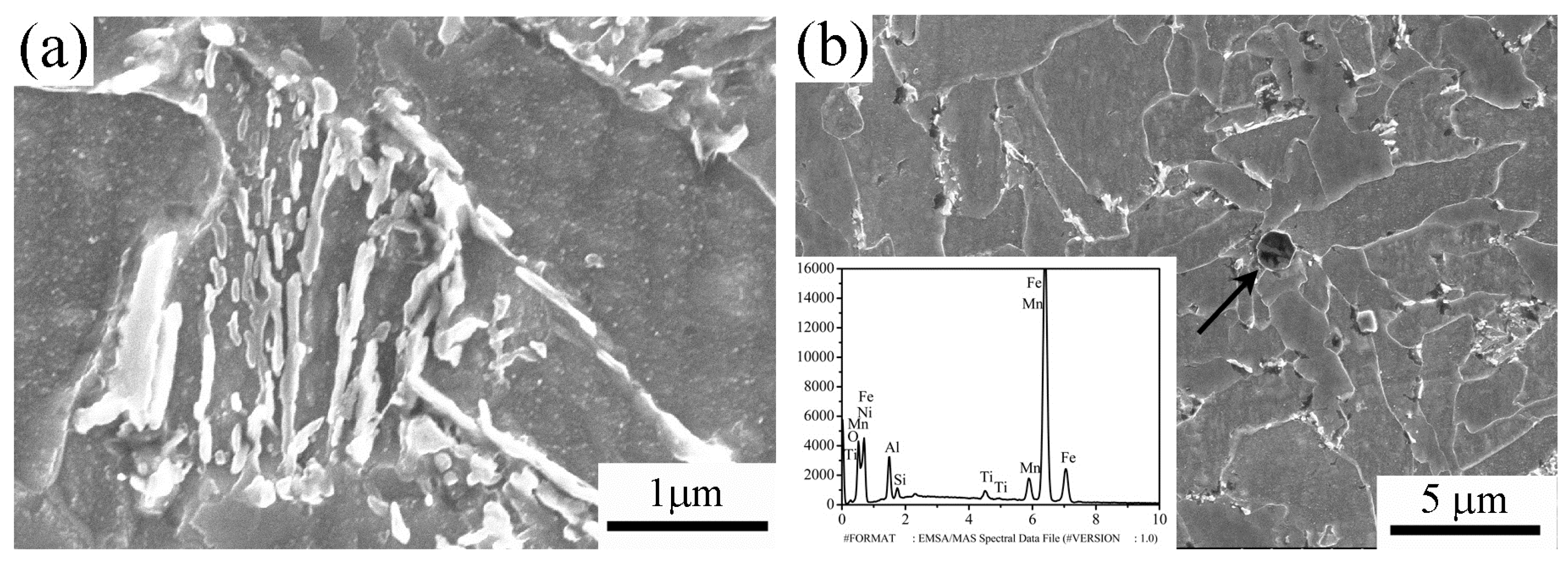
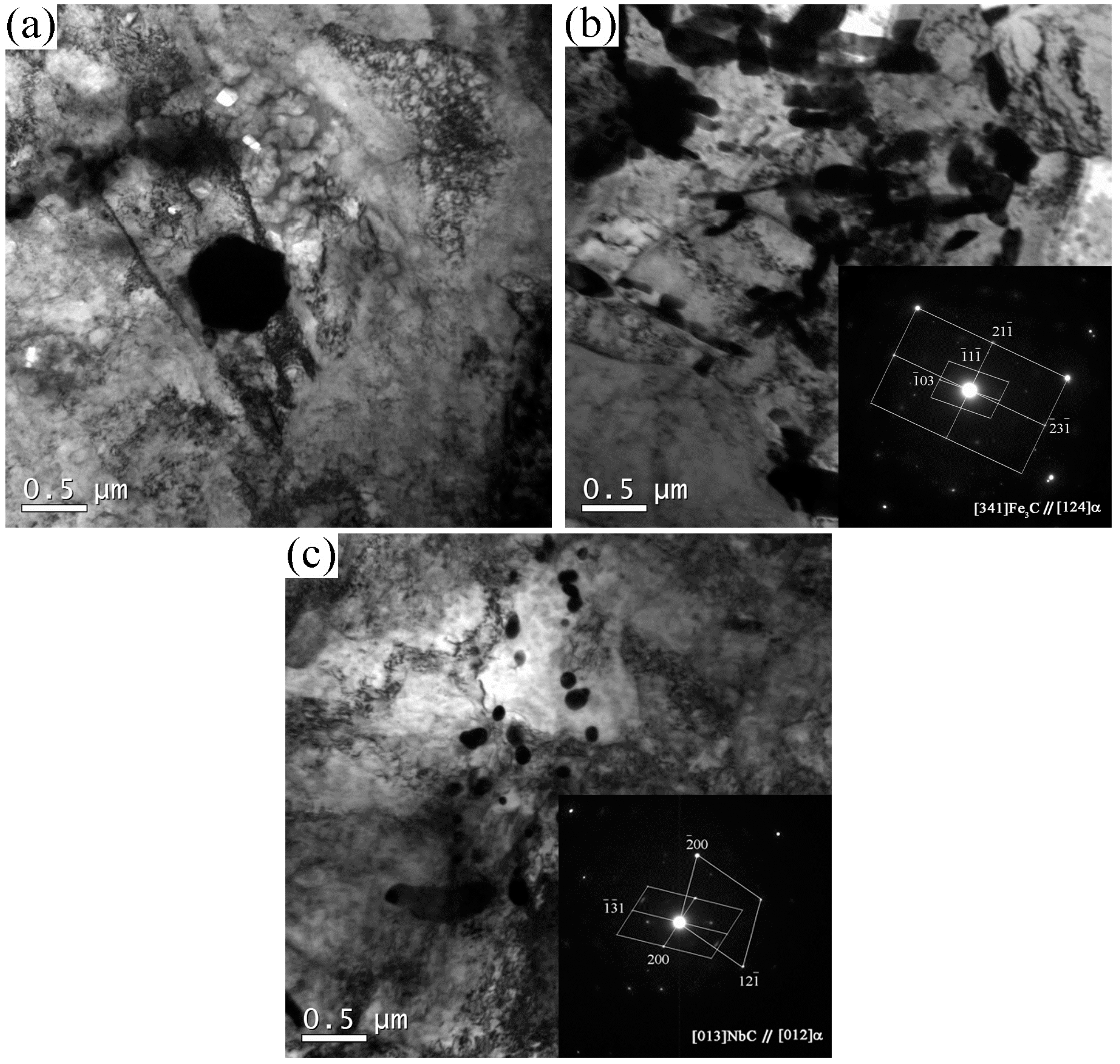
3.3. Particles
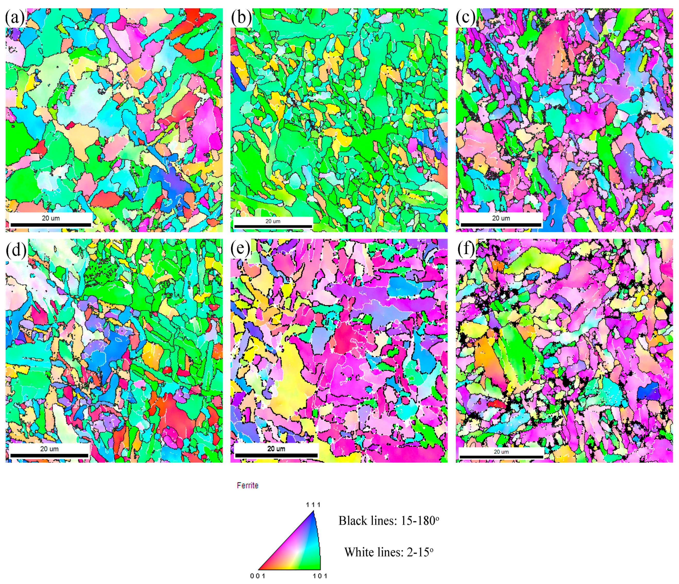
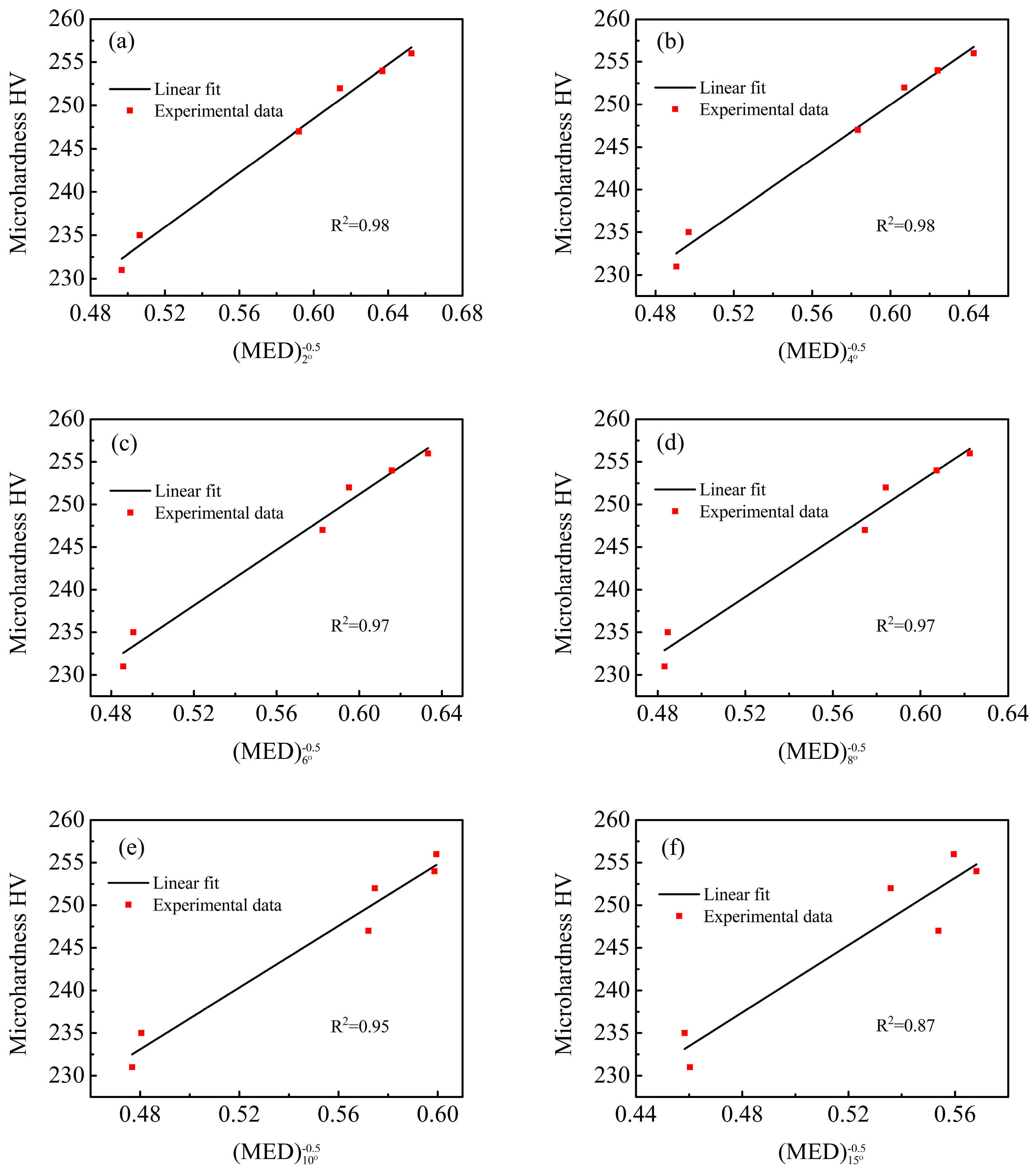
3.4. EBSD Analysis of the Microstructures
4. Conclusions
Acknowledgments
Author Contributions
Conflicts of Interest
References
- Xiao, F.R.; Liao, B.; Ren, D.L.; Shan, Y.Y.; Yang, K. Acicular ferritic microstructure of a low-carbon Mn-Mo-Nb microalloyed pipeline steel. Mater. Charact. 2005, 54, 305–314. [Google Scholar] [CrossRef]
- Wang, W.; Yan, W.; Zhu, L.; Hu, P.; Shan, Y.Y.; Yang, K. Relation among rolling parameters, microstructures and mechanical properties in an acicular ferrite pipeline steel. Mater. Des. 2009, 30, 3436–3443. [Google Scholar] [CrossRef]
- Wang, W.; Shan, Y.Y.; Yang, K. Study of high strength pipeline steels with different microstructures. Mater. Sci. Eng. A 2009, 502, 38–44. [Google Scholar] [CrossRef]
- Chung, P.C.; Ham, Y.; Kim, S.; Lim, J.; Lee, C. Effects of post-weld heat treatment cycles on microstructure and mechanical properties of electric resistance welded pipe welds. Mater. Des. 2012, 34, 685–690. [Google Scholar] [CrossRef]
- Díaz-Fuentes, M.; Iza-Mendia, A.; Gutiérrez, I. Analysis of different acicular ferrite microstructures in low-carbon steels by electron backscattered diffraction. Study of their toughness behavior. Metall. Mater. Trans. A 2003, 34, 2505–2516. [Google Scholar] [CrossRef]
- Iza-Mendia, A.; Gutiérrez, I. Generalization of the existing relations between microstructure and yield stress from ferrite-pearlite to high strength steels. Mater. Sci. Eng. A 2013, 561, 40–51. [Google Scholar] [CrossRef]
- Tang, N.C. Plastic-deformation analysis in tube bending. Int. J. Pres. Vessel. Pip. 2000, 77, 751–759. [Google Scholar] [CrossRef]
- Hu, Z.; Li, J.Q. Computer simulation on pipe bending processes with small bending radius by using local induction heating. J. Mater. Process. Technol. 1999, 91, 75–79. [Google Scholar] [CrossRef]
- Wu, D.Y.; Han, X.L; Tian, H.T.; Liao, B.; Xiao, F.R. Microstructural characterization and mechanical properties analysis of weld metals with two Ni contents during post-weld heat treatments. Metall. Mater. Trans. A 2015, 46, 1973–1984. [Google Scholar] [CrossRef]
- Banerjee, K.; Militzer, M.; Perez, M.; Wang, X. Nonisothermal austenite grain growth kinetics in a microalloyed X80 linepipe steel. Metall. Mater. Trans. A 2010, 41, 3161–3172. [Google Scholar] [CrossRef]
- Zhu, Z.; Kuzmikova, L.; Li, H.; Barbaro, F. Effect of inter-critically reheating temperature on microstructure and properties of simulated inter-critically reheated coarse grained heat affected zone in X70 steel. Mater. Sci. Eng. A 2014, 605, 8–13. [Google Scholar] [CrossRef]
- Hu, J.; Du, L.X.; Wang, J.J.; Xie, H.; Gao, C.R.; Misra, R.D.K. High toughness in the intercritically reheated coarse-grained (ICRCG) heat-affected zone (HAZ) of low carbon microalloyed steel. Mater. Sci. Eng. A 2014, 590, 323–328. [Google Scholar] [CrossRef]
- Shim, J.H.; Oh, Y.J.; Suh, J.Y.; Cho, Y.W.; Shim, J.D.; Byun, J.S.; Lee, D.N. Ferrite nucleation potency of non-metallic inclusions in medium carbon steels. Acta Mater. 2001, 49, 2115–2122. [Google Scholar] [CrossRef]
- Capdevila, C.; Garcia-Mateo, C.; Chao, J.; Caballero, F.G. Effect of V and N Precipitation on Acicular Ferrite Formation in Sulfur-Lean Vanadium Steels. Metall. Mater. Trans. A 2009, 40, 522–538. [Google Scholar] [CrossRef]


| Elements | C | Mn | Si | P | S | Mo | Ni | Cr | Cu | V | Nb | Ti | Al | N | B | Ceq 1 | Pcm 2 |
|---|---|---|---|---|---|---|---|---|---|---|---|---|---|---|---|---|---|
| Amount | 0.06 | 1.67 | 0.28 | 0.019 | 0.005 | 0.161 | 0.52 | 0.123 | 0.105 | 0.01 | 0.036 | 0.015 | 0.019 | 0.008 | 0.0008 | 0.44 | 0.18 |
| Reheating Temperature (°C) | Tempering Temperature (°C) | Charpy Impact Energy (−40 °C, J) | Microhardness (HV) | ||||
|---|---|---|---|---|---|---|---|
| Discrete Values | Average Value | Error Range | Discrete Values | Average Value | Error Range | ||
| 990 | 550 | 115, 152, 126 | 131 | ±21 | 248, 257, 257, 246, 253 | 252 | ±6 |
| 680 | 109, 132, 146 | 129 | ±20 | 249, 254, 252, 230, 250 | 247 | ±17 | |
| 1030 | 550 | 138, 143, 118 | 133 | ±15 | 268, 250, 256, 259, 249 | 256 | ±12 |
| 680 | 96, 92, 70 | 86 | ±16 | 255, 259, 259, 254, 243 | 254 | ±11 | |
| 1080 | 550 | 45, 18, 24 | 29 | ±16 | 230, 238, 244, 229, 232 | 235 | ±9 |
| 680 | 16, 19, 37 | 24 | ±13 | 229, 238, 235, 235, 220 | 231 | ±11 | |
| Reheating Temperature (°C) | Tempering Temperature (°C) | Fraction of Low Angle Boundaries, % | Fraction of High Angle Boundaries, % | (MED)2° (µm) | (MED)15° (µm) |
|---|---|---|---|---|---|
| 990 | 550 | 15.8 | 57.3 | 2.7 | 3.5 |
| 680 | 21.4 | 58.7 | 2.8 | 3.3 | |
| 1030 | 550 | 11.2 | 58.8 | 2.3 | 3.2 |
| 680 | 16.3 | 54.6 | 2.5 | 3.1 | |
| 1080 | 550 | 17.2 | 36.3 | 3.9 | 4.8 |
| 680 | 18.2 | 17.6 | 4.1 | 4.7 |
© 2016 by the authors; licensee MDPI, Basel, Switzerland. This article is an open access article distributed under the terms and conditions of the Creative Commons by Attribution (CC-BY) license (http://creativecommons.org/licenses/by/4.0/).
Share and Cite
Han, X.-L.; Wu, D.-Y.; Min, X.-L.; Wang, X.; Liao, B.; Xiao, F.-R. Influence of Post-Weld Heat Treatment on the Microstructure, Microhardness, and Toughness of a Weld Metal for Hot Bend. Metals 2016, 6, 75. https://doi.org/10.3390/met6040075
Han X-L, Wu D-Y, Min X-L, Wang X, Liao B, Xiao F-R. Influence of Post-Weld Heat Treatment on the Microstructure, Microhardness, and Toughness of a Weld Metal for Hot Bend. Metals. 2016; 6(4):75. https://doi.org/10.3390/met6040075
Chicago/Turabian StyleHan, Xiu-Lin, Da-Yong Wu, Xiang-Ling Min, Xu Wang, Bo Liao, and Fu-Ren Xiao. 2016. "Influence of Post-Weld Heat Treatment on the Microstructure, Microhardness, and Toughness of a Weld Metal for Hot Bend" Metals 6, no. 4: 75. https://doi.org/10.3390/met6040075