Article

Influence of Post Weld Heat Treatment on Strength of Three Aluminum Alloys Used in Light Poles

1
Civil Engineering and Associate Dean, College of Engineering, The University of Akron, Akron, OH 44325, USA
2
Department of Civil Engineering, the University of Akron, Akron, OH 44325, USA
3
Research and Development, HAPCO, Abingdon, VA 24210, USA
4
HAPCO, Abingdon, VA 24210, USA
*
Author to whom correspondence should be addressed.
Metals 2016, 6(3), 52; https://doi.org/10.3390/met6030052
Submission received: 8 December 2015 / Revised: 12 February 2016 / Accepted: 22 February 2016 / Published: 3 March 2016
(This article belongs to the Special Issue Aluminum Alloys)

Abstract

:
The conjoint influence of welding and artificial aging on mechanical properties were investigated for extrusions of aluminum alloy 6063, 6061, and 6005A. Uniaxial tensile tests were conducted on the aluminum alloys 6063-T4, 6061-T4, and 6005A-T1 in both the as-received (AR) and as-welded (AW) conditions. Tensile tests were also conducted on the AR and AW alloys, subsequent to artificial aging. The welding process used was gas metal arc (GMAW) with spray transfer using 120–220 A of current at 22 V. The artificial aging used was a precipitation heat treatment for 6 h at 182 °C (360 °F). Tensile tests revealed the welded aluminum alloys to have lower strength, both for yield and ultimate tensile strength, when compared to the as-received un-welded counterpart. The beneficial influence of post weld heat treatment (PWHT) on strength and ductility is presented and discussed in terms of current design provisions for welded aluminum light pole structures.

1. Introduction and Background

Over the last four decades, i.e., since the early 1970s, structural aluminum alloys have been used in a myriad of applications, primarily because they can offer an attractive combination of strength, are light in weight, have a high strength-to-weight (σ/ρ) ratio, and, most importantly, are cost efficient [1]. Many products are being increasingly fabricated from 6XXX-series aluminum alloys due to their innate ability to be extruded into complex shapes, coupled with their receptiveness to welding and their notable resistance to environment-induced degradation or corrosion [2]. Understanding the weldability and resultant mechanical properties is important in an attempt to put these alloys to efficient use. It is uncommon for an aluminum alloy to be welded with no influence on microstructure and resultant mechanical properties, such as strength. However, precipitation heat treatment does offer the promise of minimizing the negative effects of welding on the mechanical properties of the family of 6XXX alloys. A product of considerable practical interest and significance is welded aluminum light poles [3,4].
A widely-used method for joining the alloys of aluminum is welding. A few noteworthy examples related to the commercial industry include the following: (i) fabrication of rail vehicles; (ii) marine structures; (iii) pressure vessels; (iv) automotive components; and (v) structures in the civil construction industry. A few noteworthy advantages of the welding process include the following: (a) high joint efficiencies; (b) flexibility; (c) speed; and (d) a low fabrication cost [5]. Welding involves “localized” melting of the base material; as a consequence of which, both the microstructure and resultant mechanical properties will be different from those of the base material [6]. To obtain improved properties for the welded material, component, or structure, a heat treatment is both necessary and essential [7].
Section 2.5 of the 2010 Aluminum Design Manual (ADM) provides mechanical property information for welded and, subsequently, heat treated alloys that are chosen for use in aluminum light poles [8]. Aluminum alloys 6005 and 6063 have been widely used for welded light poles. For poles manufactured from aluminum alloy 6005, welded in the T1 temper, and having a thickness less than or equal to 6.4 mm, the specifications allow the engineer to make effective use of 85% of the strength of the base metal (6005-T5) in the un-welded condition, provided that the assembly is artificially aged for 6 h at 182 °C (360 °F). Light poles fabricated from AA6063, welded in the T4 temper, and having a thickness either equal to or less than 9.5 mm, the specifications allow for use of 85% of strength of the base metal, i.e., AA6063-T6, provided the welded assembly is artificially aged for 6 h at 182 °C (360 °F). It is important to note that the 85% percent “rule” is permissible and allowed when welding aluminum alloy 6005 and aluminum alloy 6063 using aluminum alloy 4043 as the filler material. The basis for these provisions within the Aluminum Design Manual (ADM) was the result of round robin tests carried out in the early 1960s and up to the late 1970s [9,10]. Most importantly, results of these studies were never published in the open literature, and some test records have been either misplaced or lost over the years. A careful review of the available test data from an earlier round robin test program, using statistical techniques inscribed within the 2010 Aluminum Design Manual (ADM), was considered to be both incomplete and inconclusive [9,10].
The focus of the current study was a determination of the mechanical properties of welded and artificially aged aluminum alloys 6061, 6063 and 6005A having thicknesses commensurate with what is currently being used in aluminum alloy light poles. Further, the study provided an opportunity to carefully examine the extrinsic influence of welding on intrinsic microstructural effects in an attempt to characterize the microstructure-mechanical property relationships. Much of the work examining the relationships can be found elsewhere [11,12]. This paper focuses on the mechanical properties of Post Weld Heat Treated (PWHT) aluminum alloys that are preferentially chosen for use in light poles. In recent years, the influence of post-weld heat treatment subsequent to hybrid welding of aluminum alloy 5754 was carefully studied and the test results and observations documented in the open literature [13].

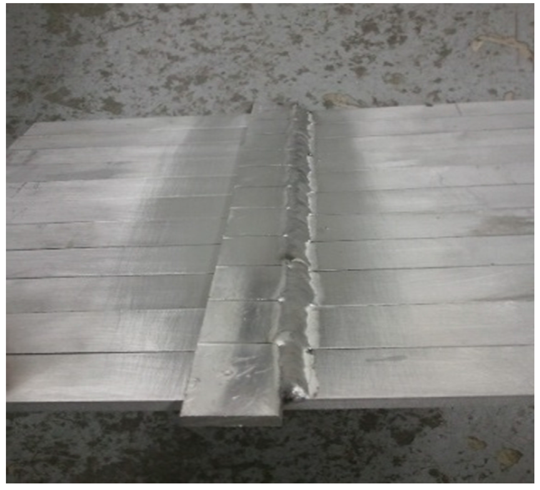
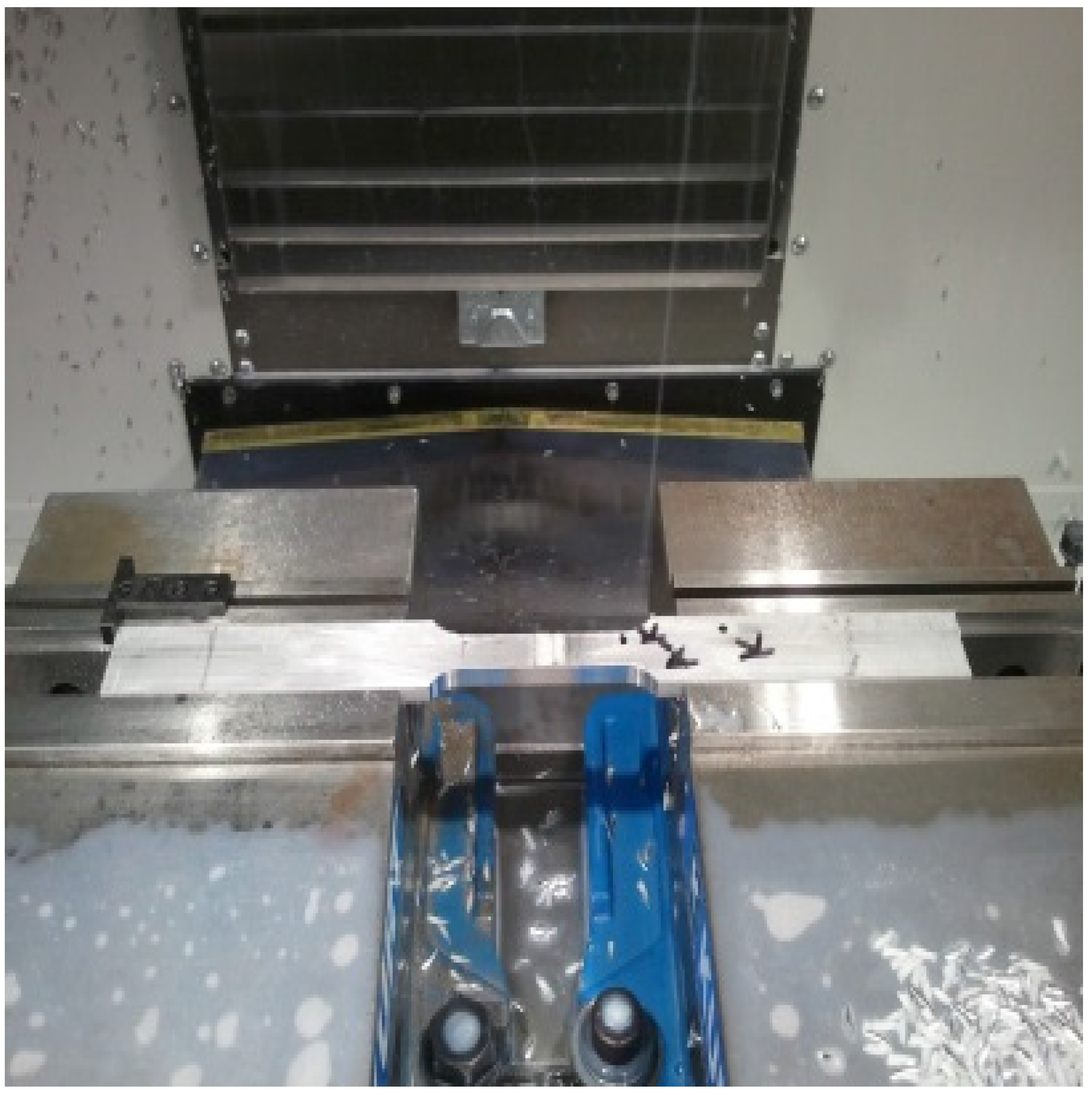
2. Specimen Preparation and Mechanical Testing

The parent materials chosen for use in this research study were the three aluminum alloys: (i) AA6063-T4, (ii) AA6061-T4, and (iii) AA 6005A-T1. All the three aluminum alloys were obtained in the as-extruded form. Blanks were then saw cut from the extruded sections. The tensile test specimens were precision machined from the as-extruded sections, the test specimen measured 6.4 mm (1/4 in) and 9.5 mm (3/8 in) in thickness, for both aluminum alloy 6063 and aluminum alloy 6061. Samples prepared for aluminum alloy 6005A were taken from extruded sections that measured 3.2 mm (1/8 in) in thickness. Different material thicknesses were selected based on their historical use in light pole applications, as well as provisions documented in the Aluminum Design Manual (ADM) for the purpose of enabling a scientific comparison of the tensile response.
The nominal compositions of the three alloys are given in Table 1 [14].
The filler metal used for this study was AA4043, as is common in the fabrication of light poles and for purpose of welding the 6XXX series alloys [15]. Fillet welds were used to form heat-affected zones across samples in an attempt to examine the influence of “localized” heating on the base material. The test samples, with short cover plates and a fillet weld, are shown in Figure 1. Gas metal arc welding (GMAW) was successfully used to deposit the weld metal using the technique of spray transfer, with the current varying from 120 to 220 A at a voltage of 22 V. The filler wire was 2.4 mm (3/32 in) in diameter with the shielding gas was 100 percent argon. Gas metal arc welding was chosen and used since it continues to be acceptable and preferentially chosen for use in a wide spectrum of industrial-related applications.
After the welds were placed, a Bridgeport vertical axis milling machine was used to remove the fillet and cover plate, leaving only the parent metal strip containing the heat affected zone (HAZ). Upon removal of the fillet welds and cover plates, each metal strip was transformed into a tensile specimen using a computer numerical control (CNC) machine (Model: HAAS) (Figure 2). A number of un-welded strips were also machined to provide tensile samples. A sizeable number of both the welded and parent metal tensile samples were chosen for the purpose of subsequent heat treatment.
The heat treatment process followed procedures outlined in ASTM B918-01 [16]. Essentially, a precipitation type heat treatment was used, and this is referred to as post-weld heat treatment (PWHT). For the three chosen aluminum alloys (6005A, 6061 and 6063), the specifics of the treatment involved an initial soak at a temperature of 182 °C (360 °F) for six hours, followed by cooling in ambient air (27 °C). In this research study, both the welded (PWHT) and unwelded (PHT) tensile samples were subject to artificial aging at 182 °C (360 °F) for six hours. The resultant tempers were expected to be near the T6 condition for aluminum alloy 6063 and aluminum alloy 6061. Test specimens fabricated from aluminum alloy 6005A were expected to be close to a T5 temper following artificial aging. The guaranteed minimum strengths for extrusions of AA6005A-T5, AA6061-T6 and AA 6063-T6 were 262 MPa, 262 MPa and 207 MPa, respectively. The three aluminum alloys chosen for this research study had strengths that exceeded the guaranteed minimum yield strength and ultimate tensile strength that is recommended for use in conventional structural design.
A few tensile samples consisting of welded and parent metal AA6005A were re-solution heat treated and subsequently aged. The re-solution heat treatment followed guidelines given in Volume 4 of the ASM Handbook “Heat Treating” [17]. The re-solution treatment process consisted of an initial soaking of the test specimens at 529 °C (985 °F) for a full 60 min. This was followed by a rapid quench in a solution mixture of 60%/40% water/glycol. This treatment was expected to place both the coarse and intermediate-size constituent particles back in solution. If left unattended, the 6XXX-series alloys used in this research study would be expected to naturally age with time at an ambient temperature (27 °C). Following re-solution heat treatment, a selected number of specimens were subjected to artificial aging. The primary purpose of testing the re-solution heat treated and aged AA6005A samples was to compare the tensile properties with the 6005A counterpart.
Tensile samples of aluminum alloys 6061, 6063 and 6005A were tested in uniaxial tension in each of the following conditions:
  • As-Received (AR-6063, AR-6061 and AR-6005A).
  • As-Received and artificially aged (AR+PHT-6063, AR+PHT-6061, AR+PHT-6005A).
  • As-Welded (AW-6063, AW-6061, AW-6005A).
  • Welded and subsequently heat treated (PWHT-6061, PWHT-6063, PWHT-6005A).
  • As-Received and As-Welded subjected to re-solution heat treatment and aging (SHT+PHT-6005A).
Individual test specimens were placed in a universal test machine (Model: Warner-Swasey) and deformed in uniaxial tension up until failure by separation. An extensometer was fixed along the gage section of each sample to obtain a record of the axial strain during loading. Data from each test were recorded on a PC-based data acquisition system and subsequently used to develop the stress versus strain response. The engineering stress versus engineering strain curves were compared to provide an understanding of the response of the chosen test specimens when subjected to uniaxial deformation. Both yield strength and ultimate tensile strength values were obtained for each test sample, and the lower bounds statistically determined. The lower bound strengths were compared with the minimum guaranteed design values for the chosen aluminum alloy.

3. Results and Discussion
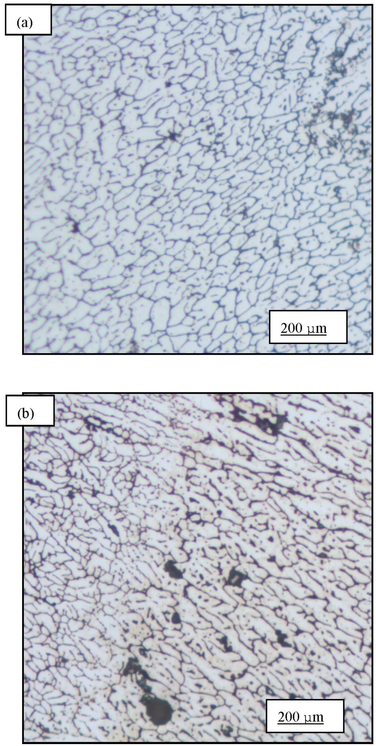
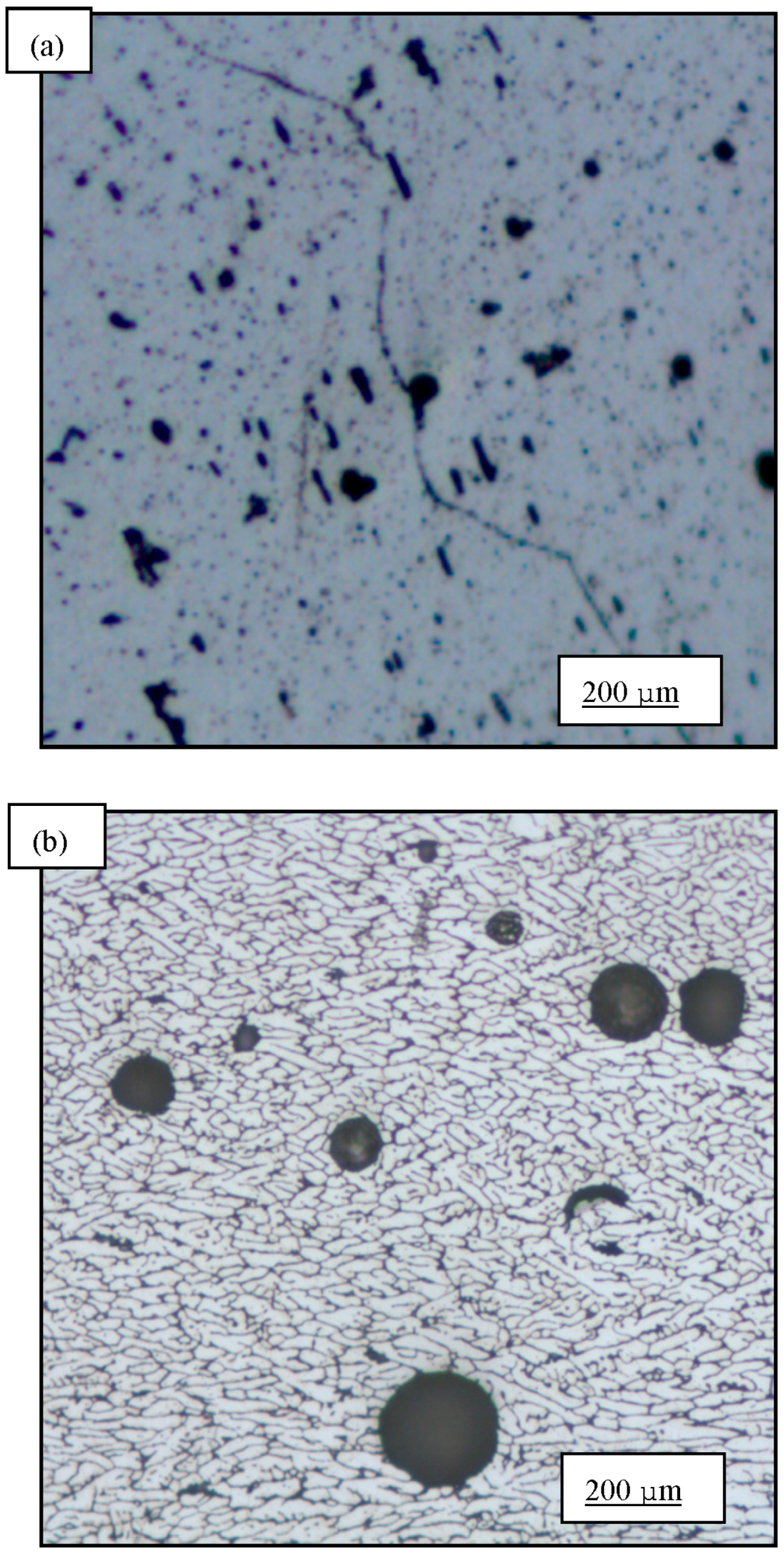
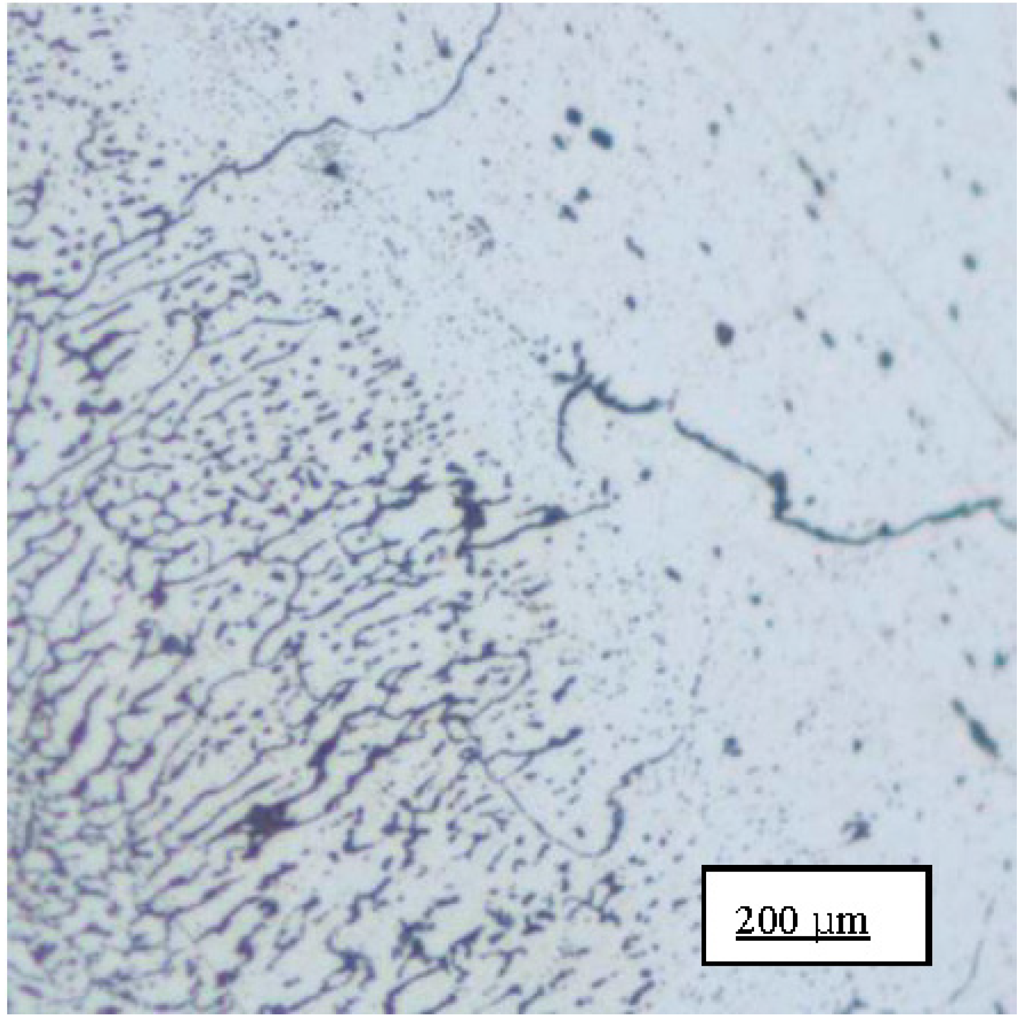
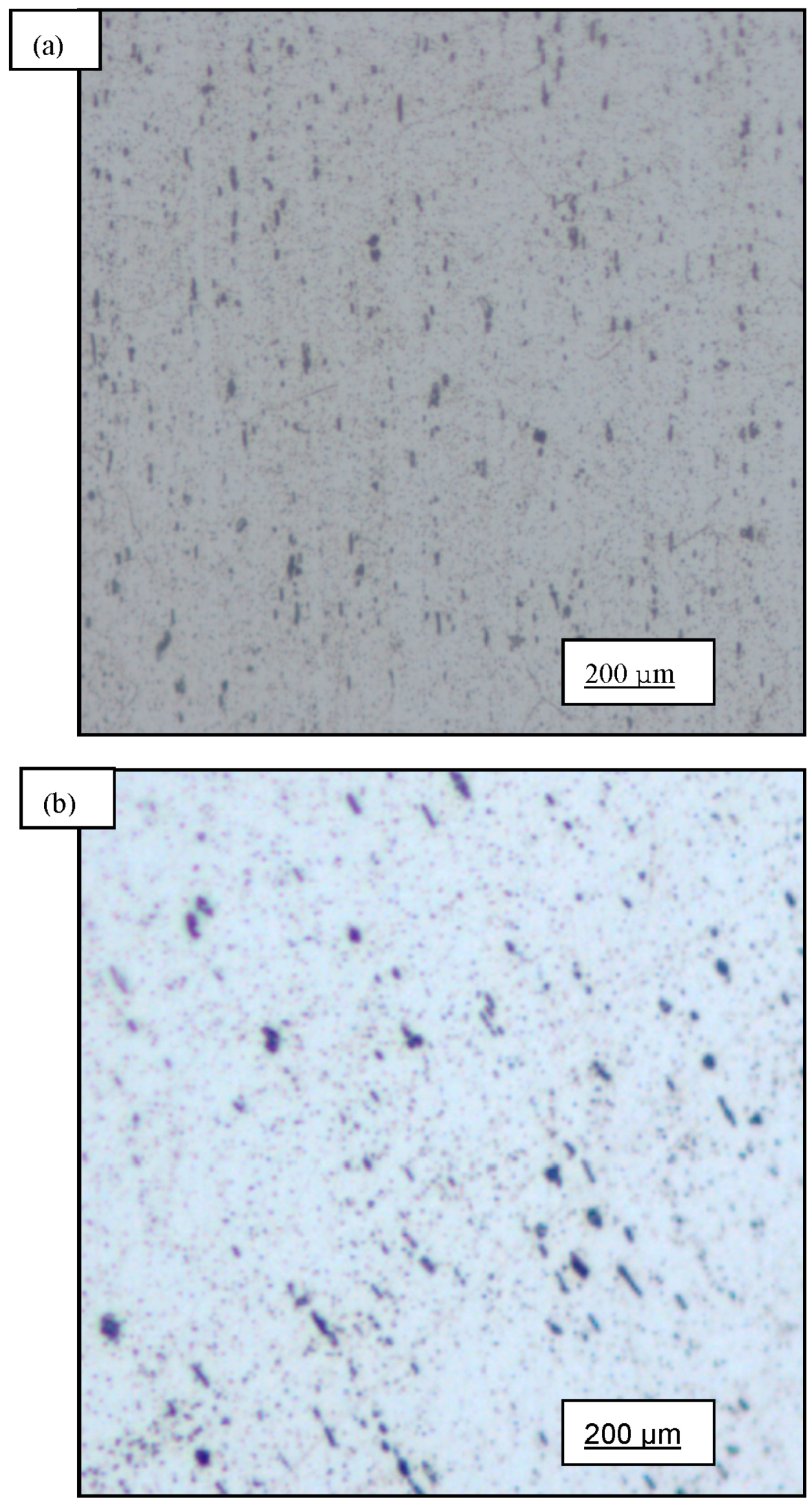
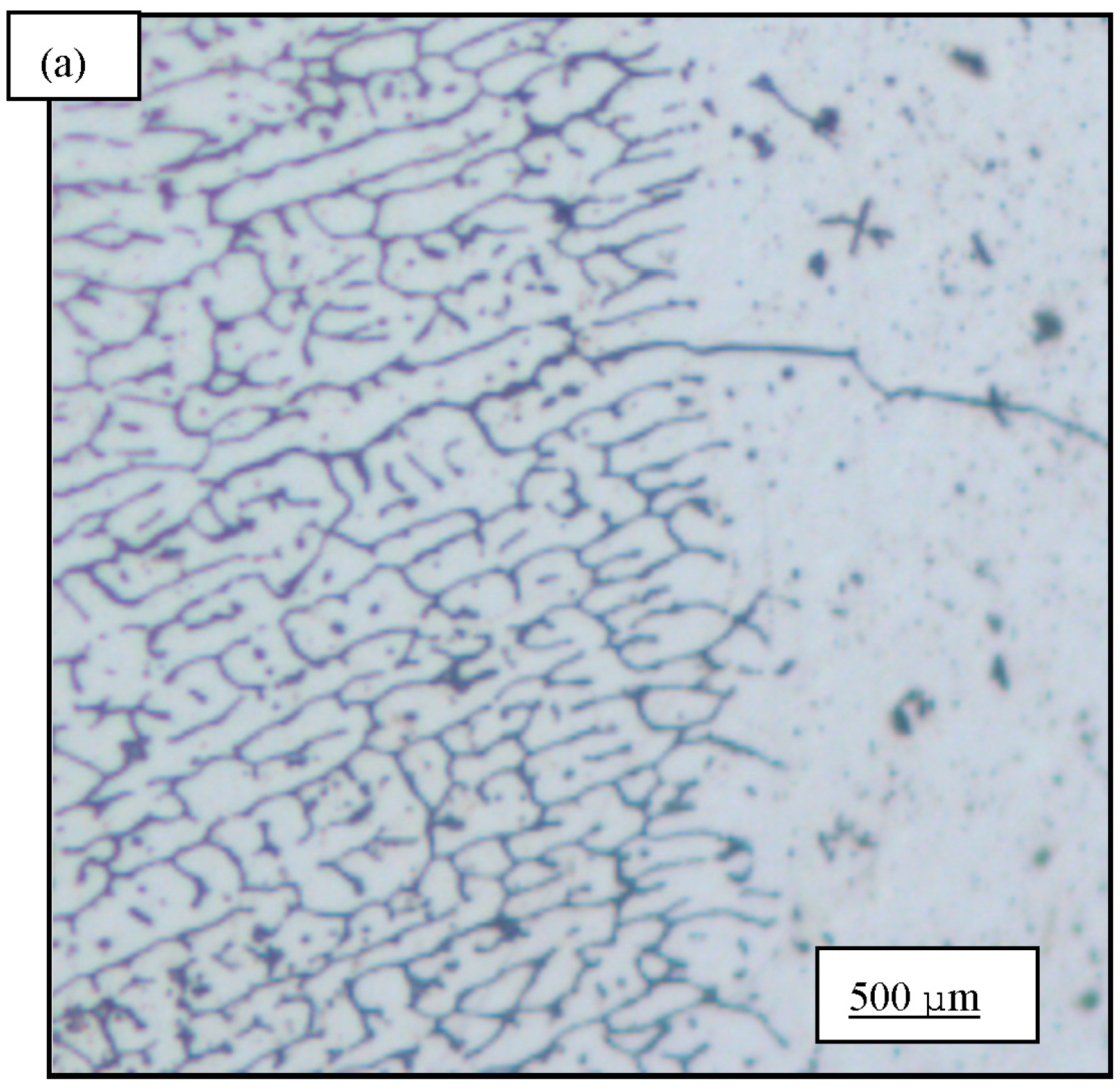
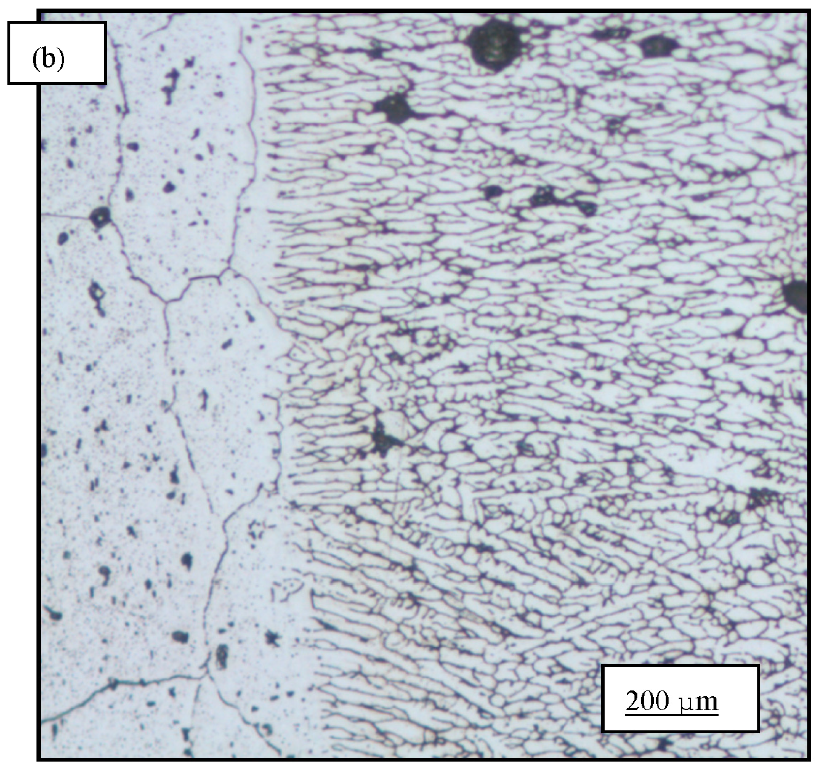
3.1. Microstructure

Light optical micrographs were taken over a range of low magnifications, revealed the initial microstructure of AA6061 in the (a) as-received (AR); (b) as-welded (AW); (c) as-received plus precipitation heat treated (AR+PHT); and (d) post weld heat treated (PWHT) conditions. The as-received alloy revealed a random distribution of both coarse and intermediate size intermetallic particles (Figure 3a,b). These intermetallic particles result from the presence and availability of residual elements, such as iron and silicon [18,19]. As documented elsewhere, these particles were identified to be Al12Fe3Si, Al15(FeMn)3Si and Al5FeSi [18,19,20]. The iron-rich intermetallic particles range in size from 1 to 10 microns and are potential sites for the early initiation of microscopic damage during plastic deformation. The manganese-rich particles in the chosen aluminum alloys help in controlling both grain size and grain growth during solidification. Micrographs of the alloy in the as-welded (AW) condition revealed fine recrystallized grains in the region of the weld bead (Figure 4a). By comparison, the weld bead in the post weld heat treated condition is shown in Figure 4b. A noticeable difference in microstructure between the weld bead and base metal is evident along the interface between the two regions (Figure 5a,b). The microstructure of aluminum alloy 6061, in the as-received plus precipitation heat treated condition revealed a significant volume fraction of both coarse and intermediate size second-phase particles in the base metal (Figure 6a). These particles were randomly dispersed throughout the microstructure. The as-welded and post weld heat treated samples revealed very well defined grains that could be classified as being: (i) small in size and of varying shape (Figure 6b), and (ii) distributed randomly through the microstructure of the base metal. The microstructure at the interface of the base metal and weld bead is shown in Figure 12. Fine microscopic cracks are evident and can be attributed to melting of the low melting point constituents both at and along the grain boundaries.

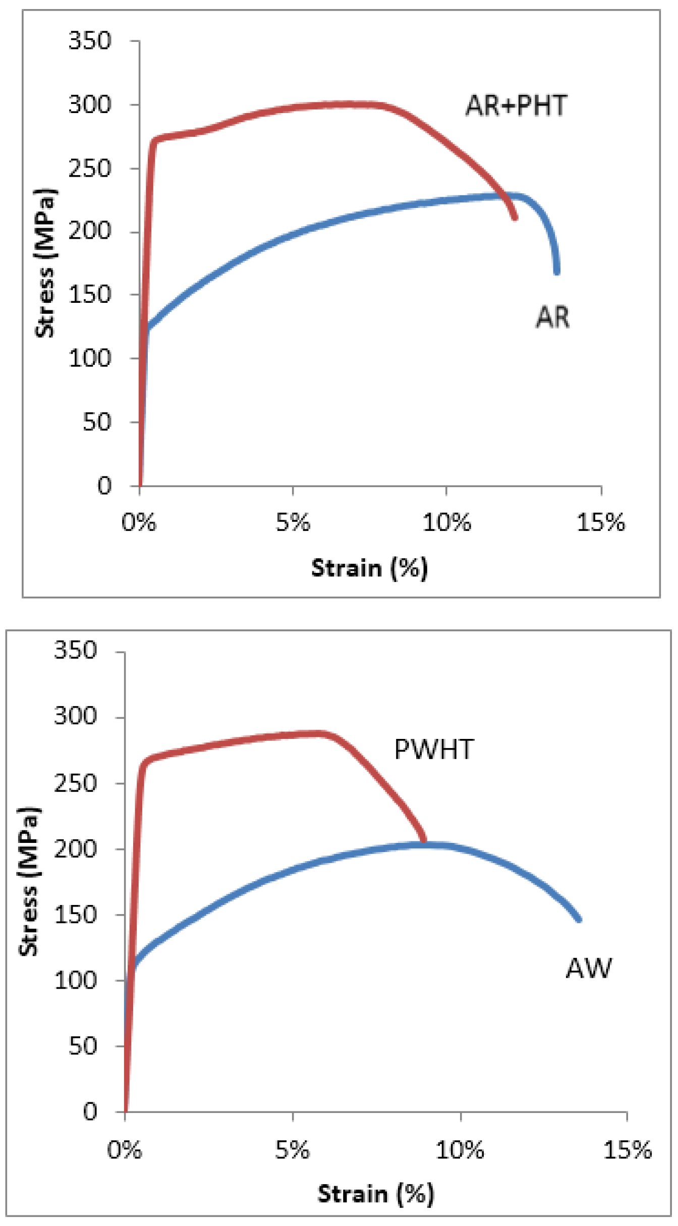
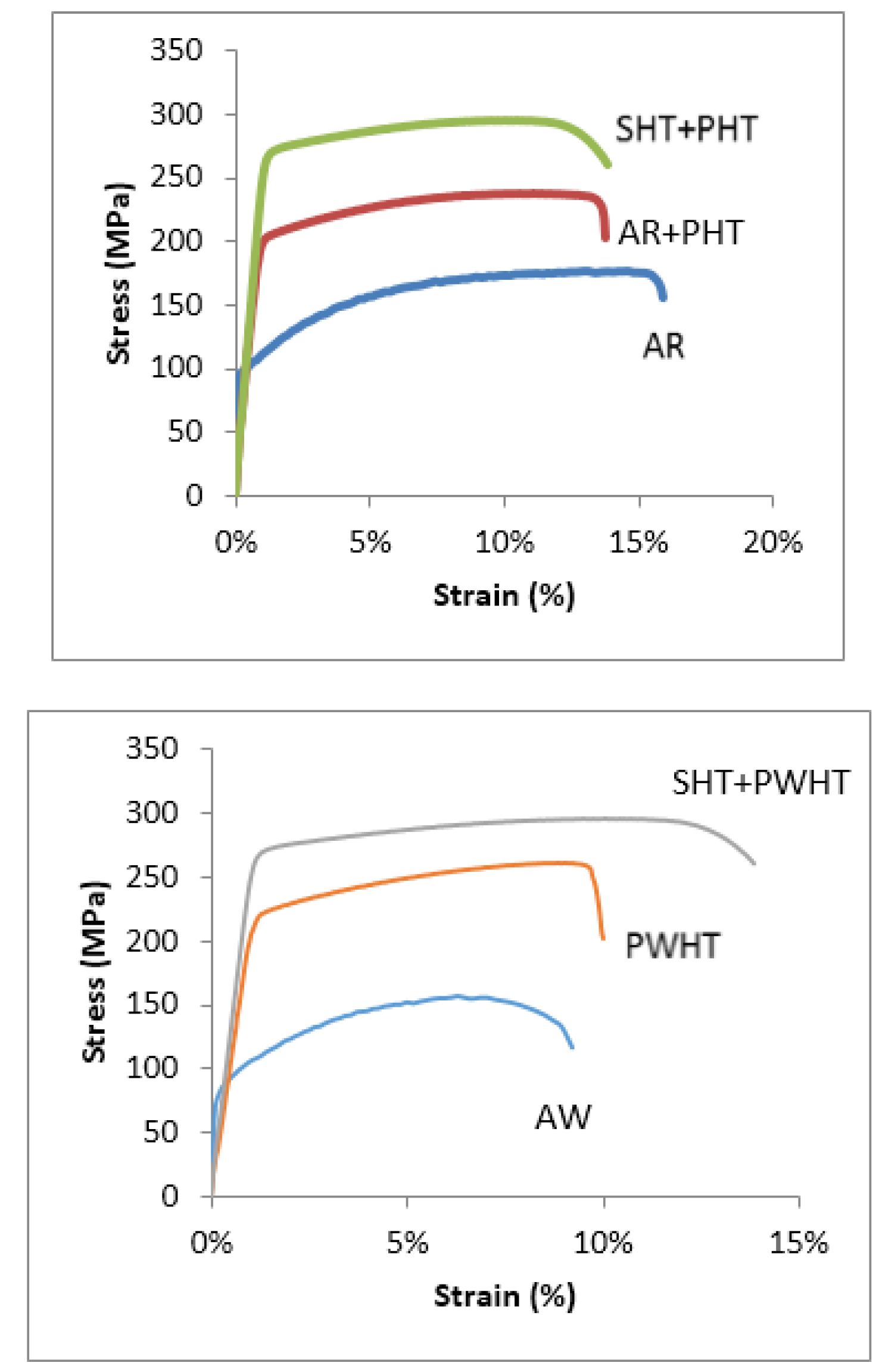
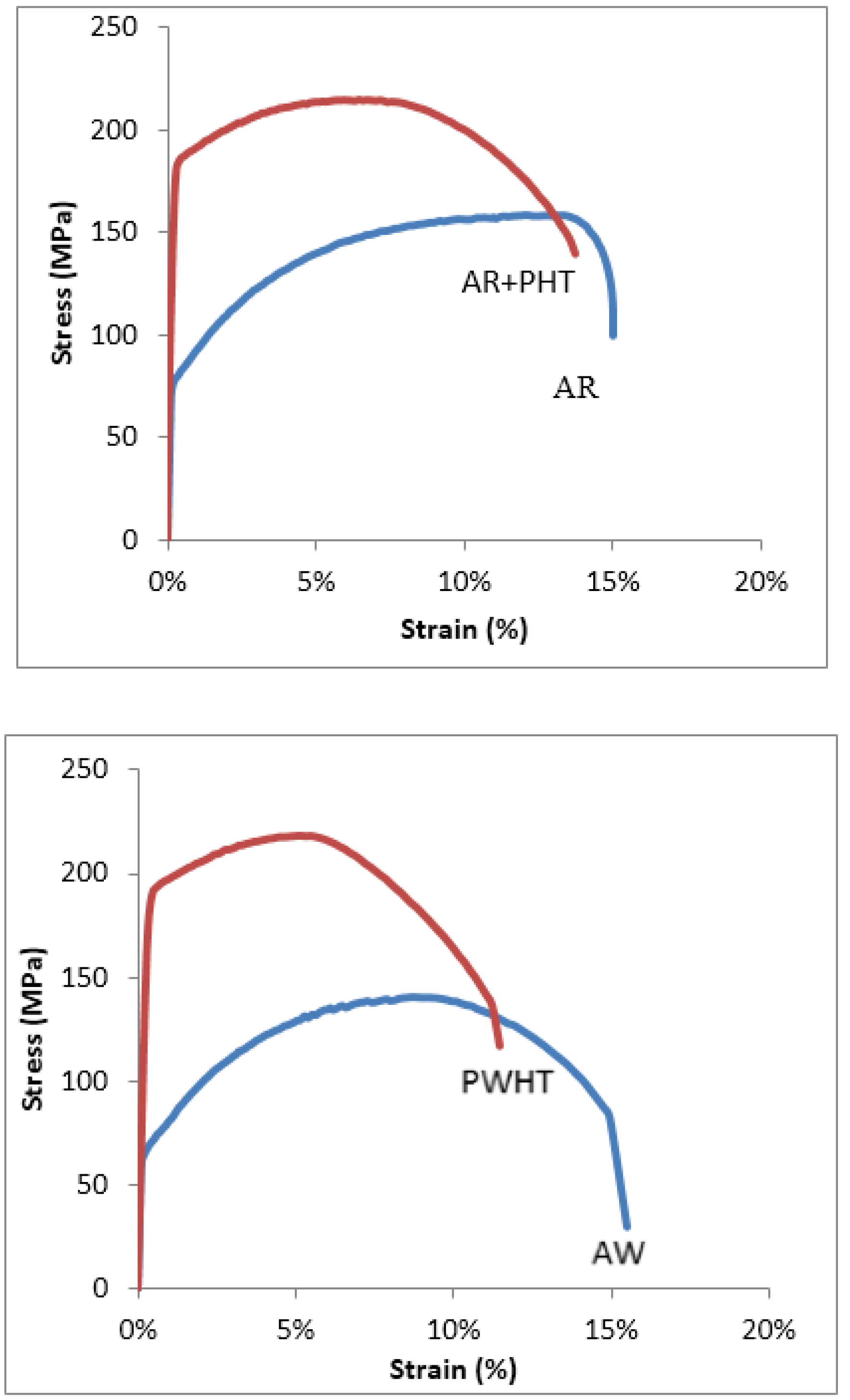
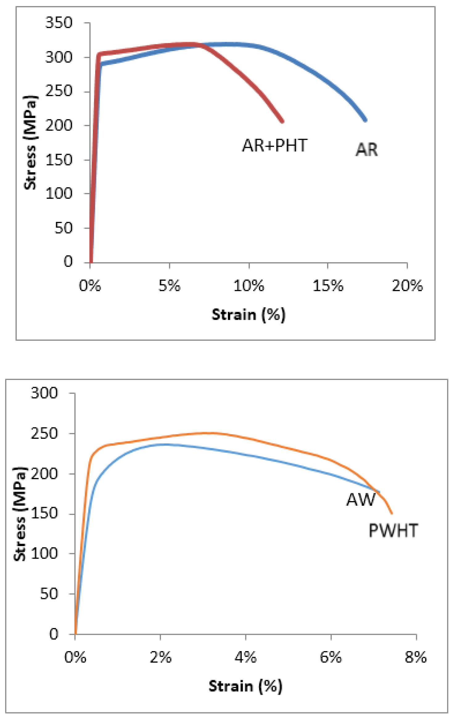
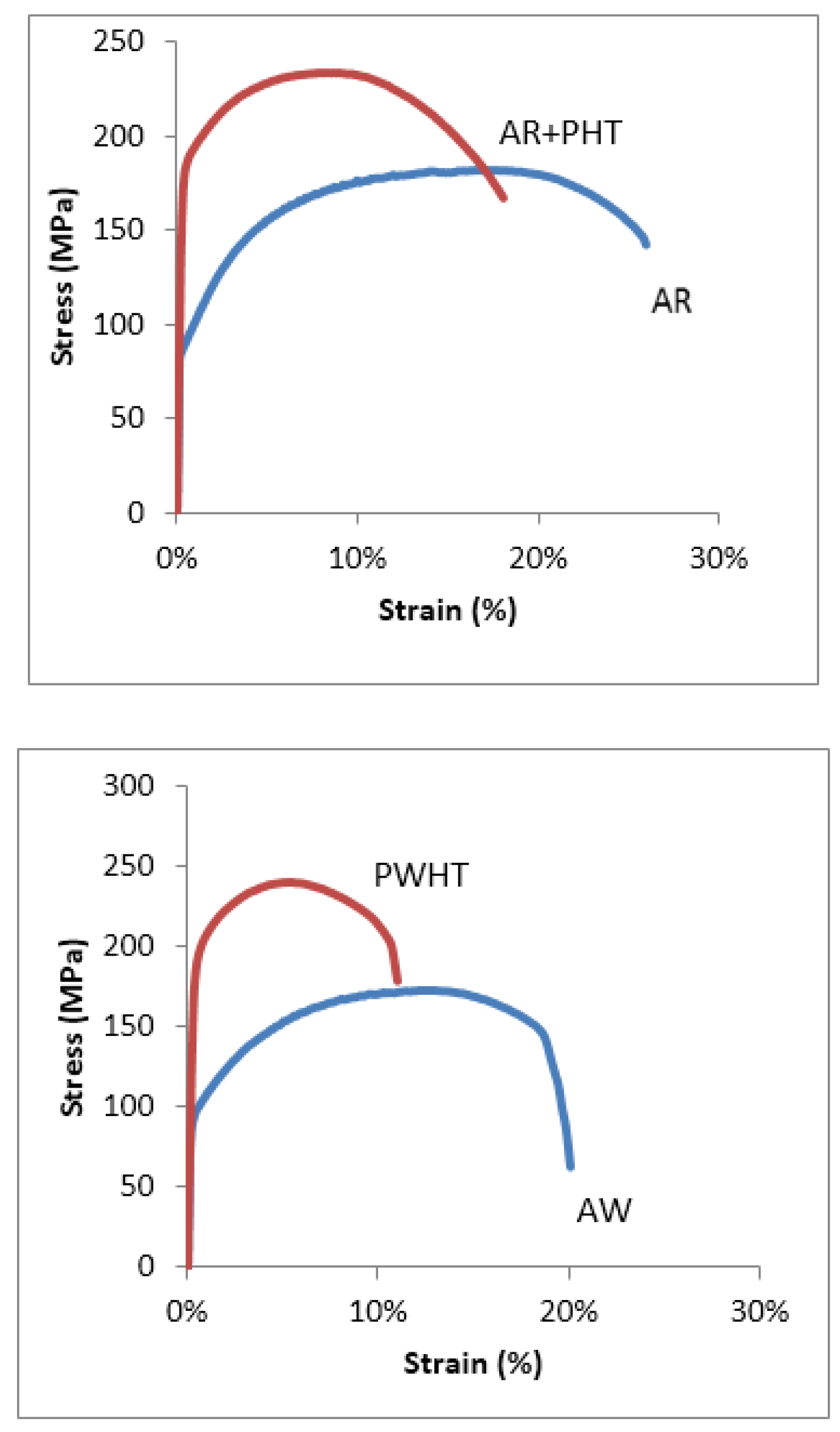
3.2. Typical Stress-Strain Response

In Figure 7, Figure 8, Figure 9, Figure 10 and Figure 11 the typical stress versus strain behaviors for the aluminum alloys and test conditions employed used this study are shown. Each plot shows the stress versus strain variation for either the as-received (AR) and as-received and aged (AR+PHT) or the as-welded (AW) and the Post Weld Heat Treated (PWHT) counterpart. Figure 11, shows the stress versus strain response for the re-solution heat treated and aged 6005A (SHT+PHT or SHT+PWHT).
In general, artificial aging increased the strength of aluminum alloy 6063 for both the as-received (AR) and as-welded (AW) conditions. The observed increase in strength was far more pronounced for the aluminum alloy material that was 6.4 mm (1/4 in) thick. This is not unexpected, primarily because a thicker material necessitates the need for additional heat input during welding.
As in the case of AA6063, all tensile specimens of AA6061 responded positively to heat treatment, showing an observable gain in strength. The increase in strength was evident even for the 9.5 mm (3/32 in) thick specimens that were initially welded and subsequently aged. However, the ultimate tensile strength obtained for the thicker specimen (t = 9.5 mm) was found to be lower than the test specimens that measured 6.4 mm (1/4 in) in thickness.
Both as-received (AR) and as-welded (AW) specimens of AA6005A, having a thickness of 3.2 mm (1/8 in), responded favorably to heat treatment, with a significant increase in both yield strength and tensile strength. Test specimens of aluminum alloy 6005A, in both the as-received (AR) and as-welded (AW) conditions, that were solution heat treated and subsequently aged showed the largest gain in strength when deformed in uniaxial tension.

3.3. Analysis of the Results

Welding did have an influence on both microstructure and mechanical properties of the chosen 6XXX series aluminum alloys. A similar influence of welding, i.e., hybrid welding, was observed to have a noticeable influence on weld quality, microstructure and mechanical properties of aluminum alloy 5754 [13] and an experimental Al–Mg alloy [21]. The influence of welding differs depending on the following: (a) the alloy chosen; (b) the welding process used; (c) the parameters employed; and (d) overall quality of the weld. The type of joint and thickness of the starting material does have an influence on heat input, microstructure and resultant strength. Not surprisingly, this study of 6063, 6061 and 6005A aluminum alloys revealed that selective artificial aging or heat treatment increased the mechanical strength of the alloys. The observed increase in strength for the PWHT samples can be attributed to the existence of diffusion-assisted mechanisms that favor an initial increase in Guinier Preston (GP) zones coupled with a hinderance caused to the movement of dislocations as a consequence of the formation and presence of matrix strengthening precipitates. The precipitates in the PWHT alloy are finer and more uniformily distributed in the aluminum alloy metal matrix. This favors an increase in dislocation density, which contributes to the observed improvement in both yield strength and tensile strength.
When subjected to “localized” heat input as a direct consequence of welding, the chosen aluminum alloys experienced a decrease in strength when compared to strength of the as-received condition. The decrease in strength can be essentially attributed to changes in intrinsic microstructural features of the starting material as a consequence of the heat input during welding. A majority of the as-welded (AW) samples broke in an area adjacent to the weld; normally on the side of the weld to which more heat was applied. The heat-affected zone (HAZ) was observed to have lower strength when compared to the base metal.
A statistical analysis, using the guidelines established in the 2010 edition of the Aluminum Design Manual, coupled with the published guaranteed minimum strengths for AA6061, AA6063 and AA6005A, was used to determine reasonable design minimum strength for the samples that were subject to post weld heat treatment. The minimum tensile strength and yield strength for the PWHT tensile samples was established using the following equation:
σ min = σ avg k S σ
where
  • σmin = calculated minimum stress for the PWHT specimens
  • σavg = average tensile or yield strength for a given alloy in the PWHT condition
  • k = statistical coefficient based on the number of tests, n
  • Sσ = standard deviation of the test results for the particular alloy
Results of the analysis of the strength of the PWHT specimens are summarized in Table 2. Detailed in Table 2 are: (a) the alloys studied; (b) thicknesses; (c) average yield strength and average ultimate tensile strength; (d) the number of tests in the data set; (e) the standard deviation; (f) the calculated minimum yield strength and ultimate tensile strength; (g) the ratio of the calculated minimum yield strength to the guaranteed minimum yield strength for the base alloy; as well as (h) ratio of the calculated minimum ultimate strength to the guaranteed minimum strength for the base alloy. Ratio of the calculated minimum yield strength to guaranteed minimum yield strength varied from 0.5 to a high of 0.99. Ratio of the calculated minimum ultimate strength to guaranteed strength varied from 0.66 to a high of 0.98. The lower values (0.5 and 0.68) correspond to 6061 having a thickness of 9.5 mm (3/8 in) that was post weld heat treated and tested. In order to obtain test specimens of aluminum alloy 6061 that were 9.5 mm (3/8 in) thick, blanks were removed from an extrusion that had a initial thickness of 12.7 mm (1/2 in), and subsequently milled to the required thickness of 9.5 mm (3/8 in). While this may have had some influence on the test results, Table 2 shows that for both AA6063 and AA6061, the data for the 9.5 mm (3/8 in) thick specimens had noticerably larger standard deviations for both yield strength and ultimate tensile strength when compared to the specimens that measured 6.4 mm (1/4 in) in thickness. This is attributed to the increased heat input used during the welding of the thicker materials. Presented and discussed in detail elsewhere [18], an examination of the microstructure of the area immediately around the fillet revealed a few instances of visible secondary melting (Figure 12).
For the remaining alloys and thicknesses chosen, the provisions within the 2010 Aluminum Design Manual allowing the use of 85%. of the parent metal strength for PWHT light poles are confirmed. In addition, using 85%. of the base metal strength for extruded aluminum alloy AA6061, for thicknesses up to 6.4 mm (1/4 in) and welded in the T4 temper using AA4043 as filler followed by post weld heat treatment (PWHT), also conforms with the 85% rule. In summary the alloys and thicknesses include the following:
  • 6063-T4, PWHT up to 9.5 mm (3/8 in) thick and welded using AA4043.
  • 6005A-T1, PWHT up to 6.4 mm (1/4 in)thick and welded using AA4043.
  • 6061-T4, PWHT up to 6.4 mm (1/4 in) thick, and welded using AA4043.

4. Conclusions

This study examined the influence of post weld heat treatment (PWHT) on strength of three aluminum alloys that are commonly chosen for use in welded light poles. Findings of the study are as follows:
  • Heat treating (aging) the as-received (AR) material increased both the yield strength and ultimate tensile strength of all the alloys.
  • Post weld heat treating increased both the yield strength and ultimate tensile strength of the three alloys studied.
  • Re-solution heat treating the as-received material increased the yield strength and tensile strength of aluminum alloy 6005A.
  • Re-solution heat treating subsequent to welding, followed by post weld heat treatment was observed to increase the tensile strength and yield strength of aluminum alloy 6005A.
  • With the exception of aluminum alloy 6061 having a thickness of 9.5 mm (3/8 in), design provisions permitting use of 85% of the parent metal strengths (in T6 temper) for post weld heat treated (PWHT) light poles are confirmed. The alloys and thicknesses include: (i) 6063-T4 PWHT up to 9.5 mm thick; (ii) 6005A-T1 PWHT up to 6.4 mm thick; and (iii) 6061-T4 PWHT up to 6.4 mm thick.

Acknowledgments

This research was made possible through funds provided by the University of Akron for the graduate student and with material and technical support from Hapco Inc (Abingdon, VA, USA).

Author Contributions

Eric Hilty performed the specimen fabrication and conducted the tests. Menzemer conceived and developed the program as well as advised Hilty. He also performed the final data analysis and assisted with manuscript preparation. Srivatsan conducted examination of the material microstructures, examined the fracture surfaces and assisted with the manuscript preparation. Morrison and Minor provided the material and guidance to the study and assisted with manuscript preparation.

Conflicts of Interest

The authors declare no conflict of interest.

References

  1. Sharp, M.L. Behavior and Design of Aluminum Structures; McGraw-Hill: New York, NY, USA, 1992. [Google Scholar]
  2. Kissell, R.; Ferry, R. Aluminum Structures—A Guide to Their Specifications and Design; John Wiley and Sons: London, UK; Washington, DC, USA, 1995. [Google Scholar]
  3. Elangovan, K.; Balasubramanian, V. Influence of post weld heat treatment on tensile properties of friction stir welded AA6061 aluminum alloy joints. Mater. Charact. 2008, 59, 1168–1177. [Google Scholar] [CrossRef]
  4. Demir, H.; Gunduiz, S. The effects of aging on the machinability of 6061 aluminum alloy. J. Mater. Des. 2009, 30, 1480–1483. [Google Scholar] [CrossRef]
  5. Xu, W.; Gittos, M.F. Materials and Structural Behavior of MIG Butt Welded in 6005-T6 Aluminum Alloy Extrusions under Quasi Static and Impact Loading; TWI Report Number 14054/1/04; The Welding Institute: Cambridge, UK, 2004. [Google Scholar]
  6. Groover, M.P. Fundamentals of Modern Manufacturing, Materials, Processes and Systems, 3rd ed.; John Wiley and Sons: Hoboken, NJ, USA, 2007. [Google Scholar]
  7. Hatch, J.E. Aluminum: Properties and Physical Metallurgy, 10th ed.; American Society for Metals: Metals Park, OH, USA, 1983. [Google Scholar]
  8. The Aluminum Association. Aluminum Design Manual; Aluminum Association of America: Washington, DC, USA, 2010. [Google Scholar]
  9. Maedler, J.R. NEMA to Gordon Allison; The Aluminum Association: Washington, DC, USA, 12 February 1971. [Google Scholar]
  10. Wagoner, N. Reynolds Metals Company to R; Hartmann, Hapco: Abingdon, VA, USA, 5 August 1963. [Google Scholar]
  11. Hilty, E.; Menzemer, C.; Srivatsan, T. Influence of Welding and Heat Treatment on Microstructural Development and Properties of Aluminum Alloy 6005. In Proceedings of the 22nd PFAM Conference, Singapore, 18–20 December 2013.
  12. Hilty, E.; Menzemer, C.; Manigandan, K.; Srivatsan, T. Influence of welding and heat treatment on microstructure, properties and fracture behavior of a wrought aluminum alloy. Emerg. Mater. Res. 2014, 3, 230–242. [Google Scholar] [CrossRef]
  13. Leo, P.; D’Ostuni, S.; Casalino, G. Hybrid welding of AA5754 annealed alloy: Role of post weld heat treatment on microstructure and mechanical properties. Mater. Des. 2016, 90, 777–786. [Google Scholar] [CrossRef]
  14. The Aluminum Association. 2009 Aluminum Standards and Data; Aluminum Association of America: Washington, DC, USA, 2009. [Google Scholar]
  15. Hobart Filler Metals. Guide for Aluminum Welding; Illinois Tool Works: Chicago, IL, USA, 2013. [Google Scholar]
  16. ASTM B918-01. Standard Practice for Heat Treatment of Wrought Aluminum Alloys; ASTM International: West Conshohocken, PA, USA, 2001. [Google Scholar] [CrossRef]
  17. ASM Materials Handbook; ASM International: Materials Park, OH, USA, 1991; Volumes 4 and 6.
  18. Warmuzek, M.; Mrowkaand, G.; Sieniawski, J. Influence of Heat Treatment on Precipitation of Intermetallic Phases in Commercial AlMnFeSi Alloy. J. Mater. Process. Technol. 2004, 157–158, 624–632. [Google Scholar] [CrossRef]
  19. Gallais, C.; Simar, A.; Fabreque, D.; Denquin, A.; Lapasset, G.; de Meester, B.; Brechet, Y.; Pardoen, T. Multiscale Analysis of the Strength and Ductility of AA 6056 Aluminum Friction Stir Welds. Metall. Mater. Trans. 2007, 38, 964–981. [Google Scholar] [CrossRef]
  20. Starke, E.A., Jr. Fatigue and Microstructure; Meshii, M., Ed.; ASM International: Materials Park, OH, USA, 1979. [Google Scholar]
  21. Leo, P.; Renna, G.; Casalino, G.; Olabi, A.G. Effect of power distribution on weld quality during hybrid laser welding of an Al–Mg alloy. Opt. Laser Technol. 2015, 73, 118–126. [Google Scholar] [CrossRef]
Figure 1. Pictorial view of test sample with fillet welded lap joint.
Metals 06 00052 g001
Figure 2. A finished tensile test specimen containing a fillet weld subsequent to machining on a Computer Numerical Control (CNC) machine.
Metals 06 00052 g002
Figure 3. Light optical micrographs of aluminum alloy 6061-T4 showing microstructure the following: (a) Coarse and intermediate second phase particles in the base metal of the as-received or as-provided metal; (b) distribution of intermetallic particles in the heat-treated sample.
Metals 06 00052 g003
Figure 4. Optical micrograph of the weld pool showing fine grains of varying size and shape. (a) Grain size and morphology in the weld pool in the as-welded condition; (b) weld pool in the post weld heat-treated condition.
Metals 06 00052 g004
Figure 5. Optical micrographs showing the following: (a) Microstructure at the weld-base metal interface of the as-welded Aluminum alloy 6061-T4; (b) microstructure of the weld-base metal interface in the post weld heat treated aluminum alloy 6061.
Metals 06 00052 g005aMetals 06 00052 g005b
Figure 6. Optical micrographs of AA6061 showing the following: (a) Distribution of intermetallic particles in the base metal adjacent to the weld bead; and (b) microstructure of the weld pool of the heat-treated alloy.
Metals 06 00052 g006
Figure 7. Stress versus strain response of 6.4 mm (1/4 in) thick AA6063 in the as-received (AR), as-received plus precipitation heat treated (AR+PHT), as-welded (AW) and post weld heat treated (PWHT) conditions.
Metals 06 00052 g007
Figure 8. Stress versus Strain response of 9.5 mm (3/8 in) thick AA6063 in the as received (AR), as-received plus precipitation heat treated (AR+PHT), as-welded (AW) and post weld heat treated (PWHT) conditions.
Metals 06 00052 g008
Figure 9. Stress versus strain response of 6.4 mm (1/4 in) thick extrusion of AA6061 in the as-received (AR), as-received plus precipitation heat treated (AR+PHT), as-welded (AW), and post weld heat treated conditions.
Metals 06 00052 g009
Figure 10. Stress-strain response of 9.5 mm (3/8 in) thick extrusion of AA6061 in the as-received (AR), as-received plus precipitation heat treated (AR+PHT), as-welded (AW) and post weld heat treated (PWHT) conditions.
Metals 06 00052 g010
Figure 11. Stress versus strain response of 3.2 mm (1/8 in) AA6005A in the as-received (AR), as-received plus precipitation heat treated (AR+PHT), solution heat trearted plus precipitation heat treated (SHT+PHT), as-welded (AW), post weld heat treared (PWHT) and solution heat treated plus post weld heat treated (SHT+PWHT) conditions.
Metals 06 00052 g011
Figure 12. Optical micrograph showing region experiencing secondary melting in the weld-base metal fusion line in aluminum alloy 6061.
Metals 06 00052 g012
Table 1. Nominal composition (weight pct.) of the chosen 6XXX aluminum alloys [8].
ElementAlCrCuFeMgMnSiTiZn
6063Balance0.10.10.350.90.10.60.1Max 0.1
6005ABalance0.30.30.350.40.50.90.10.2
6061Balance0.040.150.71.20.150.80.15Max 0.05
Table 2. Data analysis summary—post weld heat treated (PWHT) yield and ultimate strengths.
AlloyThick (mm)Average Yield (MPa)Average Ultimate (MPa)Number of TestsStandard Deviation Yield/UltimateMin. Yield (MPa)Min. Ultimate (MPa)Min. Yield/ADMMin. Ult./ADM
60636.4190219100.92/0.951651930.960.93
60639.5204234212.44/1.571501990.870.96
6005A3.2227272121.0/1.052012450.830.93
6005A6.4217250120.44/0.822052290.850.87
60616.4261281150.93/0.982392580.990.98
60619.5241241244.1/3.11221730.50.66
Note: Mininimum Yield/ADM = calculated minimum yield strength from the testing program divided by the guaranteed minimum yield strength for the alloy. Minimum Ultimate/ADM = calculated minimum ultimate strength from the testing program divided by the guaranteed minimum ultimate strength for the alloy.

