1. Introduction
The wear of mechanical parts of machinery is still a current scientific, engineering and economic issue. The analysis of machine parts and structure faults shows they are often caused by tribological processes that take place at the functional surfaces. The interaction between functional surfaces in their relative motion causes adverse effects in the surface layers, leading to their deterioration. An external manifestation of this process is the removal or relocation of the functional surface particles. This process can be measured by a change in the size, weight or mechanical and physico-chemical properties. This process can be alleviated by improving the structural arrangement of nodes, the appropriate choice of materials or the creation of new surface layers [
1,
2,
3,
4,
5]. When creating the surface layers for tribological use, we often encounter hardfacing technology which enables not only the restoration of the worn surface geometry but gives it new, often better properties than the properties of the original material, which leads to a prolongation of their life [
6,
7,
8].
Welding consumables can be divided into groups according to their properties and wear resistance. The iron-based alloys include martensitic alloys, austenitic alloys and alloys with a high content of carbides [
9]. Martensitic alloys are used for the restoration of shape and for hardfacing. Their main advantages include good resistance to wear of metal-metal type, good impact resistance and acceptable abrasion resistance.
Austenitic claddings are suitable for the restoration of shape and are characterized by an excellent impact resistance and an acceptable abrasion resistance.
The advantage of alloys with high carbide content is both the excellent abrasion resistance, good heat resistance, and acceptable corrosion resistance; however, the disadvantage is a weak impact resistance [
10].
Cobalt- and nickel-based alloys are resistant to most types of wear. Due to their high cost, they are only used in cases when their properties are economically justified, such as in high temperature applications when the iron-based alloys with a high carbide content lack sufficient resistance. Nickel alloys are a slightly cheaper alternative [
11].
The most progressive additive materials for welding and thermally sprayed coatings for the conditions of abrasive, erosive, corrosive and combined stresses in mining, energy and building industries include nanostructural claddings [
12]. Characteristics of these materials not containing cobalt or nickel are based on the high content of carbide-forming and boride-forming metals Cr, Mo, W and Nb, carbon (up to 5%) and boron (5%–10%). They have an amorphous metallic glass character. Very hard and very fine nanostructures with a grain size of 2–75 nm are formed during their devitrification. A hardness of 900–1230 HV, 54–74 HRC, respectively, is reached by the resulting cladding. The base element in these alloys is iron even though, in the maximum content of alloying elements, it does not reach 50%. The claddings are carried out by MIG (Metal Inert Gas) hardfacing, and coatings are carried out by HVOF (High Velocity Oxygen Fuel) and plasma spraying technology.
Essential scientific knowledge of cladding tribology is detailed in [
13,
14] and others. These imply that one of the determining factors for the wear intensity in both the abrasive and erosive wear of claddings is their hardness. The hardness of cladding is a function of its chemical composition, the welding heat mode during hardfacing and its structure.
In the current analysis of abrasion resistance, the issue of cladding structure and substructure and their influence on abrasion resistance is not analyzed in detail. So far there is no consensus on the most appropriate type of structure in terms of resistance to abrasive wear. Most authors coincide in finding that the resistance to abrasive wear of alloys with the same hardness with a different chemical and structural composition is not the same. This depends on the hardness, the amount, the shape, the size and the distribution of structural components. Some authors consider austenitic-carbidic the most advantageous structure, others prioritize a martensitic-carbidic structure. This results from the diversity of the abrasive wear process and a wide range of real operating conditions [
6,
9,
15,
16,
17].
Structural and substructural properties can directly affect material removal. Its intensity is conditioned by the strength and cohesive properties of the submicroscopic particles of structure that are loaded by wear and abrasion. Every structural component in the process of exploitation determines the level of resistance of the whole metal with its share. In abrasive wear, two crucial stages must be distinguished. The first one is the process of forcing the abrasive into the surface where the limiting factor is the indentation hardness. The second stage is the process of surface disintegration, where the crucial role belongs to the strength of interatomic bonds and the strength of the structural components’ connection to each other at the grain boundaries [
13].
In real conditions, the failure of the material surface layers by a high-cycle contact fatigue process (abrasive particles do not notch into the surface, causing only elastic deformation), a low-cycle contact fatigue process (a plastic deformation when notching abrasive particles into the surface) and the grooving together with the segregation of worn material particles may occur at various locations of the tough material-worn surface. At a high speed of abrasive particles’ relative motion against the worn surface, it is necessary to also consider other degradation mechanisms: the heat affection of the material (tempering of steel, softening of the polymeric material), adsorption failure (reactions of the worn material with surface active agents that reduce surface hardness) and tribochemical reactions of the worn material with the environment. Although in abrasive wear of brittle materials plastic deformation occurs, the brittle fracture often determines the rate of wear. In tough materials this fault occurs probably right after the abrasive particle, due to tensile stress, acts here. The removal of the material by abrasion in brittle materials occurs by a brittle fracture rather than by the plastic deformation. Also, in the abrasive wear of heterogeneous materials which contain tough and brittle phases, infringement by brittle fracture may occur. The predominant mechanism of material removal depends on the characteristics of individual phases and their volume fractions [
14].
The stated information implies that due to the complexity of the wear process, it is necessary to design a type of cladding based on the tribological analysis and the conditions of the surface stress. This analysis, however, is for many practical cases impracticable due to the imperfection of developed procedures and, therefore, operational and laboratory tests have recently been used for the evaluation of cladding properties.
The aim of the paper is to carry out a tribological and metallographical analysis for two types of hardfacing layers. The analysis can contribute to clarification of the relationship between the microstructure and wear resistance of layers.
3. Results and Discussion
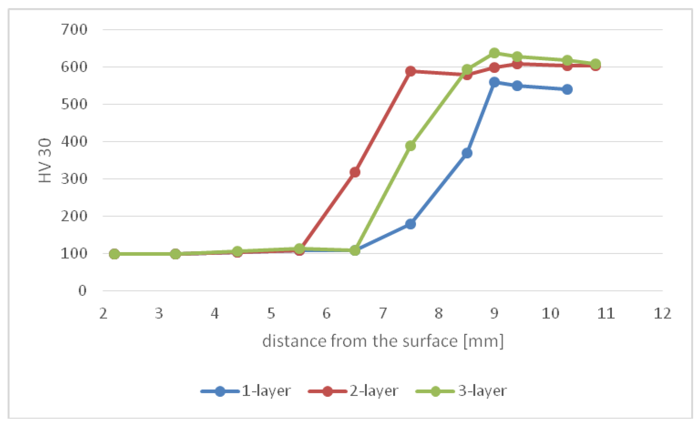
The course of the hardness of claddings E 508 B showed a strong effect of mixing the weld and base metal, as shown in
Figure 1. The hardness of the cladding in its first layer in the area of melting rises sharply to a value of 550 HV30. The second layer reaches an average value of 615 HV30, while in three-layer cladding the hardness reaches around 630 units. Theoretical and practical assumptions that the effect of mixing the base material and weld metal does not disappear until the third layer were confirmed [
13]. The transition of the hardness curves from the minimal values of the base material to the maximum values in the cladding showed a step-change.
Figure 1.
Course of hardness in cladding E 508 B with various numbers of layers.
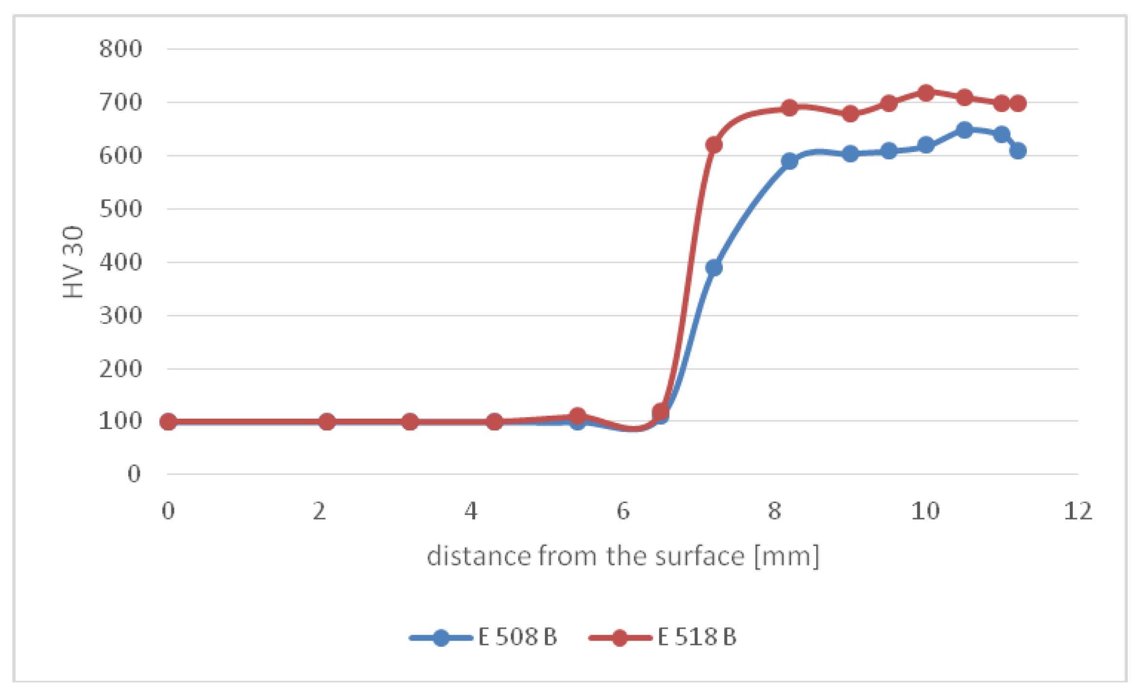
A similar course of the hardness was shown by cladding E 518 B, except that the hardness value stated by the manufacturer, which is 660 HV30, was reached already in the first layer. Maximum values obtained in individual layers did not differ significantly and reached up to 730 HV. Due to the high content of C and Cr, the mixing with the base material was significantly less.
The course of three-layer cladding hardness is shown in
Figure 2. In terms of achieved hardness, higher wear resistance can be assumed in claddings realized by the E 518 B electrode.
Figure 2.
Course of hardness in three-layer hard-faced materials.
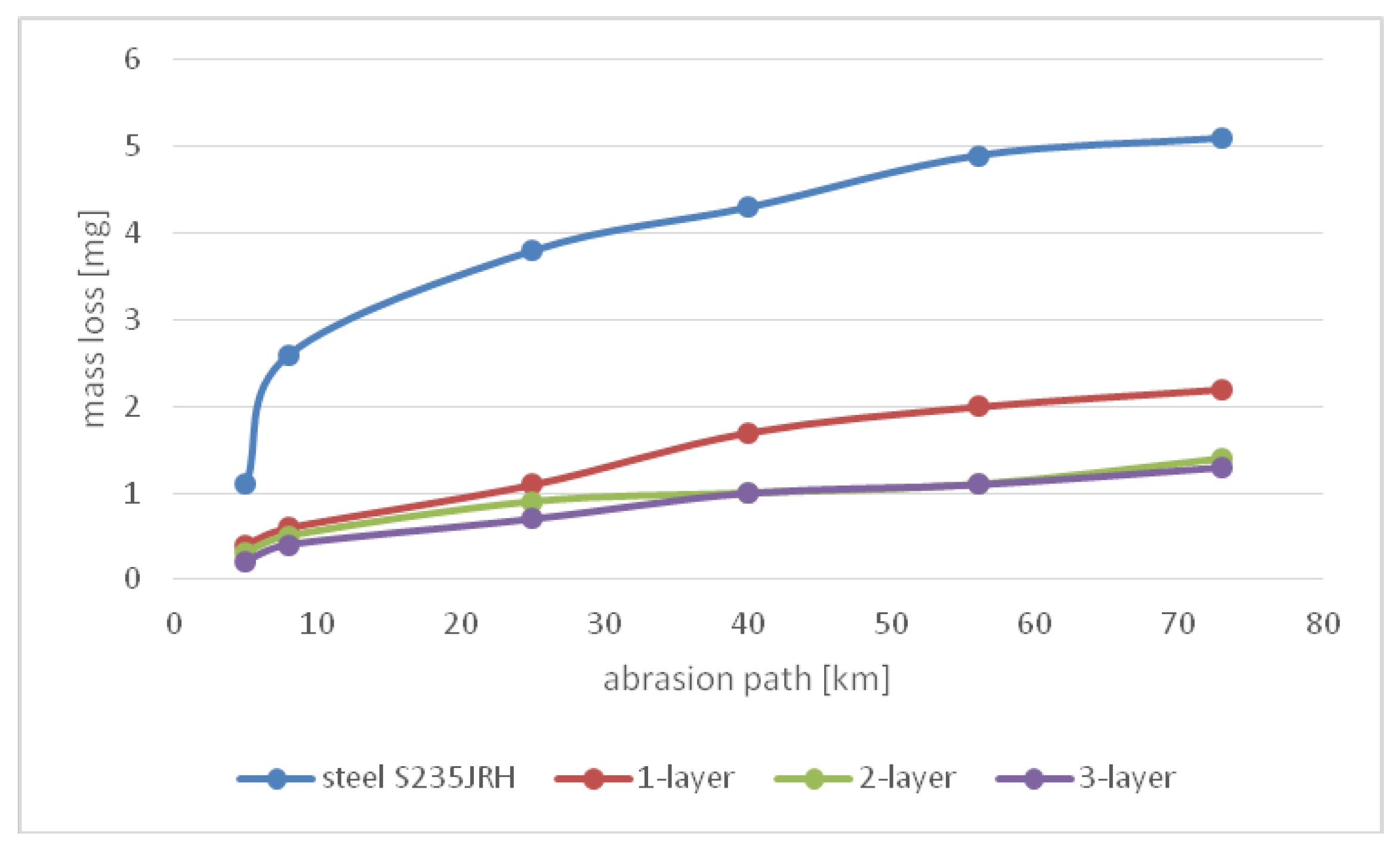
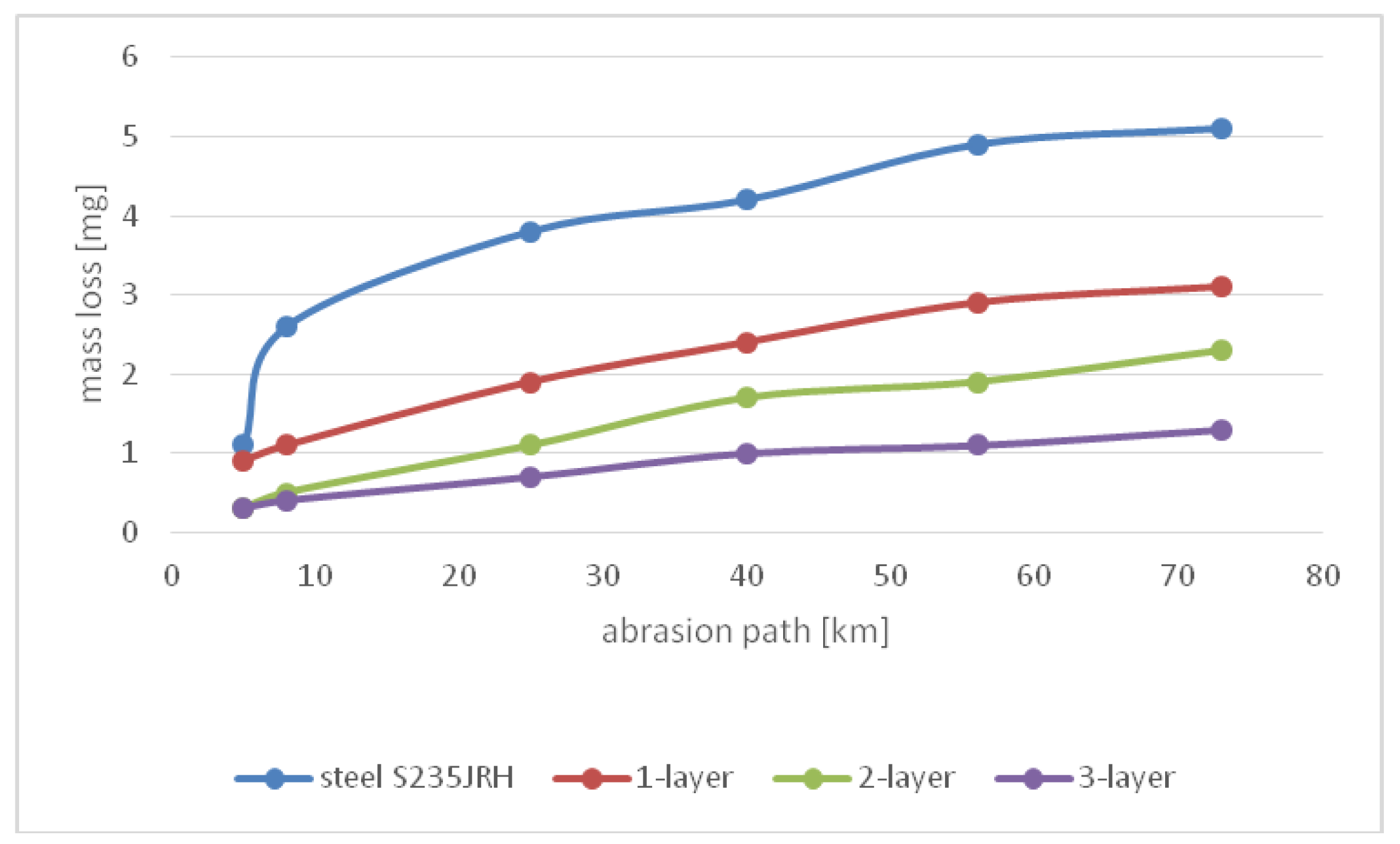
The results of abrasion resistance tests of evaluated hardfaced materials are graphically presented in
Figure 3 and
Figure 4. From these figures it can be seen that, in electrode E 508 B, single-layer claddings show higher mass loss due to the mixing of the weld metal with low-carbon steel. Despite the fact that for electrode E 518 B small differences of hardness values were reached in individual layers, there is a big difference in mass loss between single-layer and multiple-layer claddings. Compared to electrode E 508 B, it reaches higher values. The results of mass loss values of tested claddings cannot be evaluated just by a chemical composition and measured values of hardness. Most authors explain the theory of material removal in wear by a contact interaction where a plastic deformation occurs [
6]. This deformation is caused by the redistribution and dissipation of energy. The energy redistribution, followed by implementation of plastic deformation, causes a movement of anchored and free dislocations. The dislocation state of metals depends mainly on the structural state. The real structural state is therefore another factor influencing the wear resistance [
13,
15].
Figure 3.
Course of wear for hardfacing material E 508 B.
Figure 4.
Course of wear for hardfacing material E 518 B.
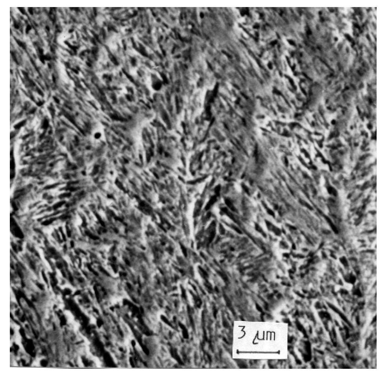
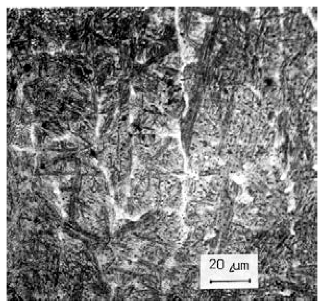
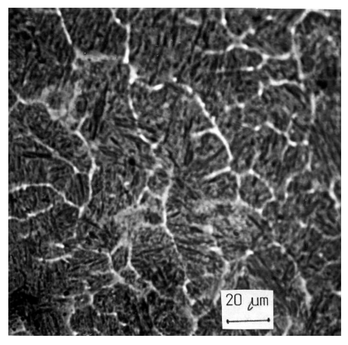
As mentioned above, the investigated claddings vary significantly in internal structure. Electrode E 508 B represents cladding based on mild steel with a content of C up to 0.4%. The relatively high content of carbide-forming elements Cr and Mo determines the formation of the bainitic matrix structure and, by bonding with carbon, creates disperse carbides reinforcing the very fine bainitic matrix. Since claddings are multilayered and multipass in a layer, the mutual thermal influence causes very heterogeneous formation of the phases. In
Figure 5 there is a structure of the first layer in the area of the mixing of the weld metal with the base material which was not thermally affected. It is a very fine bainitic structure with a ferrite net which retains the oriented nature. The microhardness of this layer reaches 424 HV 0.05. In the area of thermal affection, the grains are finer and the distinctive casting character is disappearing, as shown in
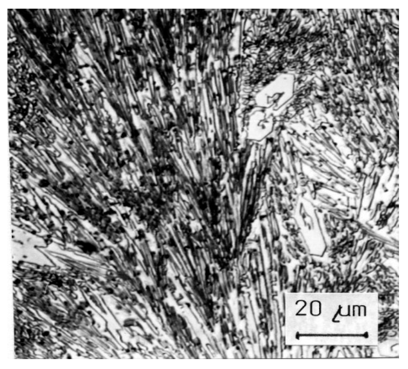
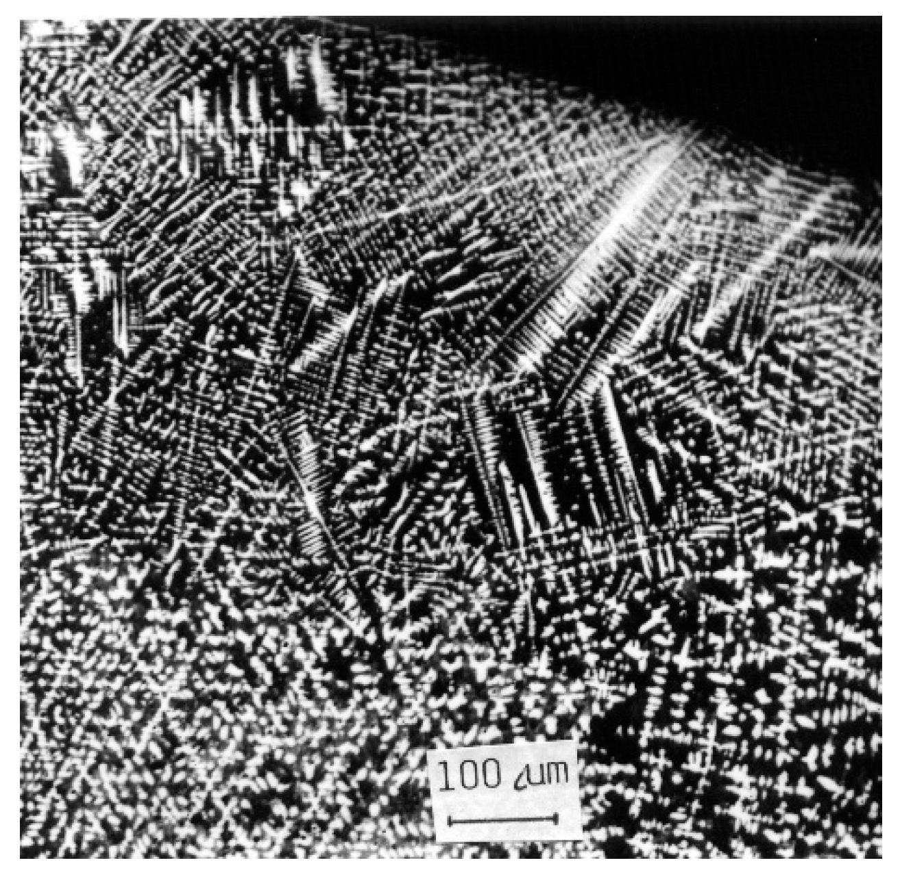
Figure 6. The similar nature of the structure is also present in the second layer, where the hardness reaches 489 HV 0.05. In the third layer of the cladding, which was not thermally affected, the distinctive casting structure is retained, as shown in
Figure 7 (538 HV 0.05). The cladding structure in the third layer in the thermally affected zone is shown in
Figure 8. In the bainitic matrix, the very dispersely formed carbidic phase can be observed. Claddings are thus characterized by a relatively tough matrix in which the very disperse carbidic phase ensures sufficiently high hardness and, therefore, abrasion resistance.
Figure 5.
Microstructure of hardfacing weld E 508 B.
Figure 6.
Thermally affected structure of the cladding E 508 B.
Figure 7.
Cast structure of hardfacing weld E 508 B.
Figure 8.
Carbidic phase in bainitic matrix of the weld E 508 B.
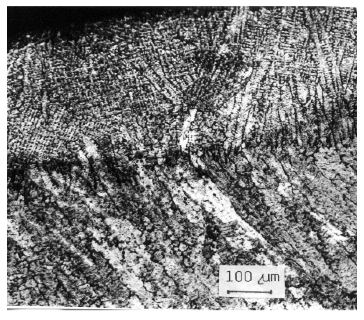
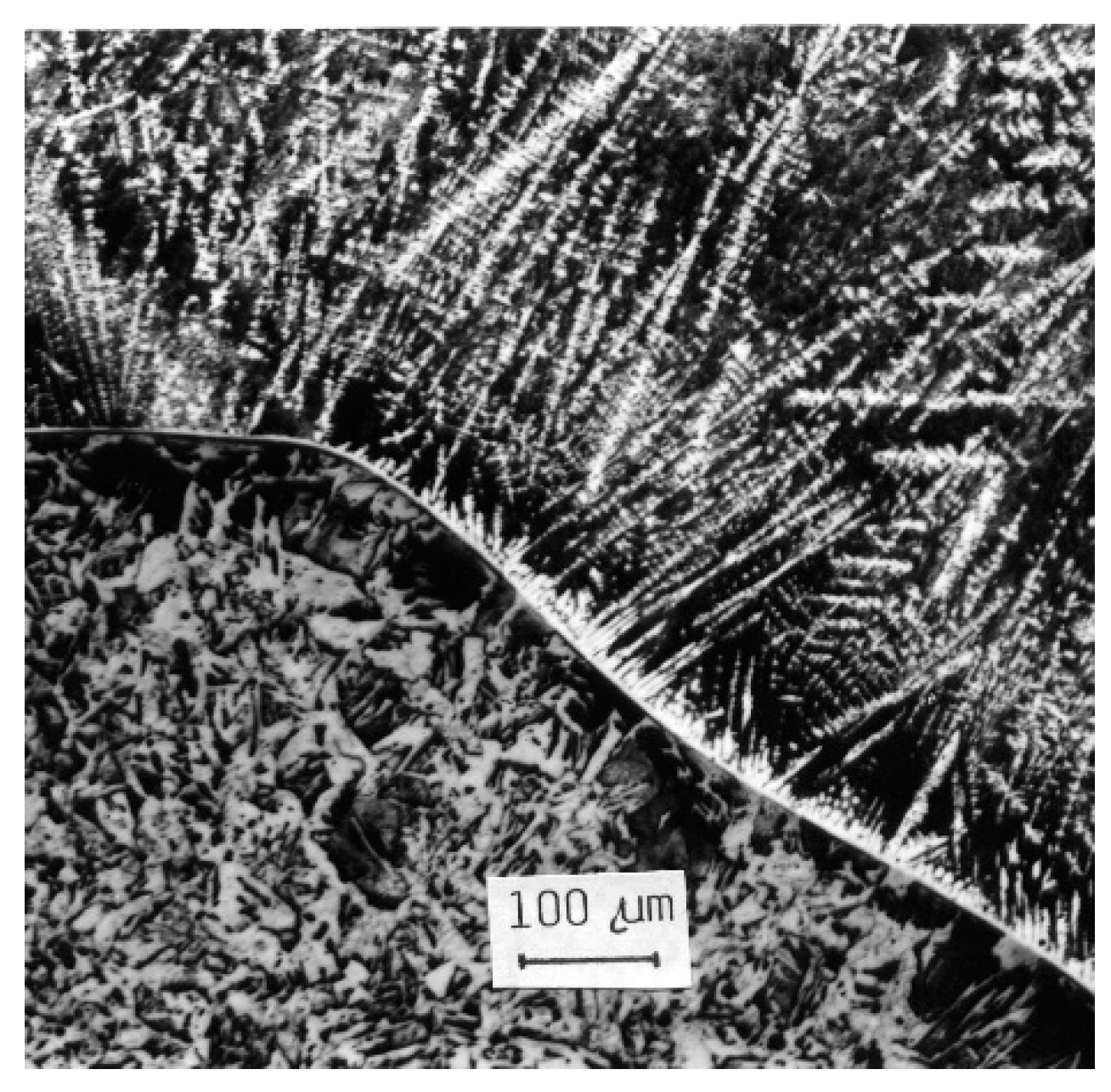
The structural composition of the claddings realized by electrode E 518 B is shifted into the area of cast iron, which is manifested by the significant dendritic character of the cast structure. The high content of C up to 3.5% and chrome up to 27.5% after the re-melting in the cladding gives a high-alloyed cast iron of ledeburitic type with a significant presence of primary and secondary carbides. The structure in the transition from the base material to the cladding is documented in
Figure 9.
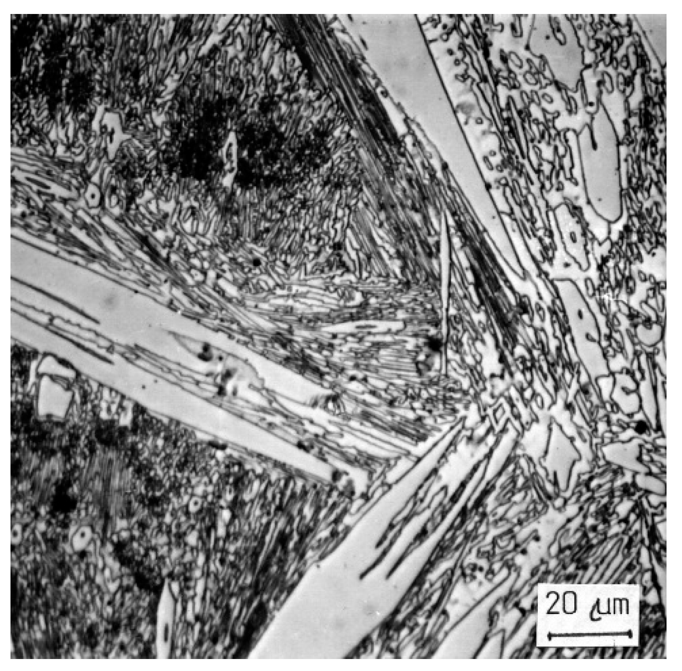
Figure 9 shows that even in the short term of the re-melting, a very thin carburized layer was formed in the base material, demonstrated by large pearlitic grains. In the areas of the cladding where the cast structure was thermally affected, a very fine, oriented needle structure (
Figure 10) or a transformed structure with large carbidic needles (
Figure 11—TMP14) was formed due to the structural transformation. The structure in the cover layers of the cladding is a casting structure with a distinct dendritic composition (
Figure 12). The average hardness of the ledeburitic matrix was of 562 HV 0.05. Large carbidic needles reached a hardness of 1630 HV 0.05 while small needles reached up to 2350 HV 0.05.
Figure 9.
Cast structure of hardfacing weld E 518 B.
Figure 10.
Detail of fine-grain structure of cladding E 518 B.
Figure 11.
Detail of massive carbidic particles E 518 B.
Figure 12.
Cast structure of hardfacing weld E 518 B.
For the creation of the fracture surface, energy is demanded and, thus, the character of the fracture, whether it is cleaving, ductile failure or decohesion along the phase boundary, also provides the resistance to separation of microparticles under surface abrasion. Therefore, the examination of these surfaces makes it possible to predict the use properties of metallic materials.
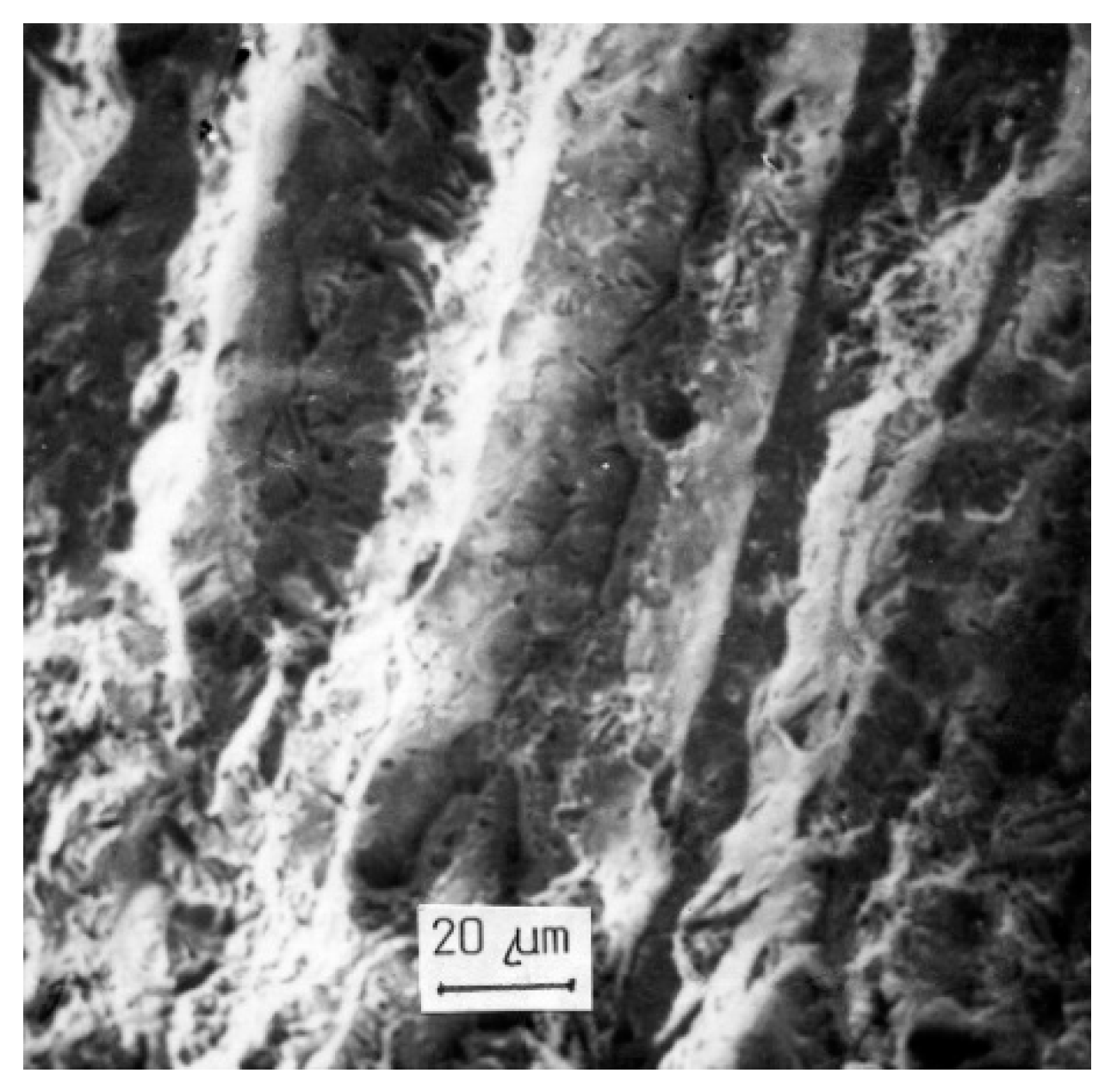
Depending on the heat affection of the structural composition, the bulk of the fracture surfaces of E 508 B under bending stress was formed by decohesive failure at the border of crystallites or dendrites, as shown in
Figure 13. Part of the surface failed by decohesion with a low power consumption—smooth facets and part of the surface failed in these claddings by pit morphology whose creation is energy-demanding and indicates the certain resistance to a brittle fracture, as shown in
Figure 14.
Figure 13.
Decohesive failure at the dendrite borders.
Figure 14.
Morphology of E 508 B cladding failure.
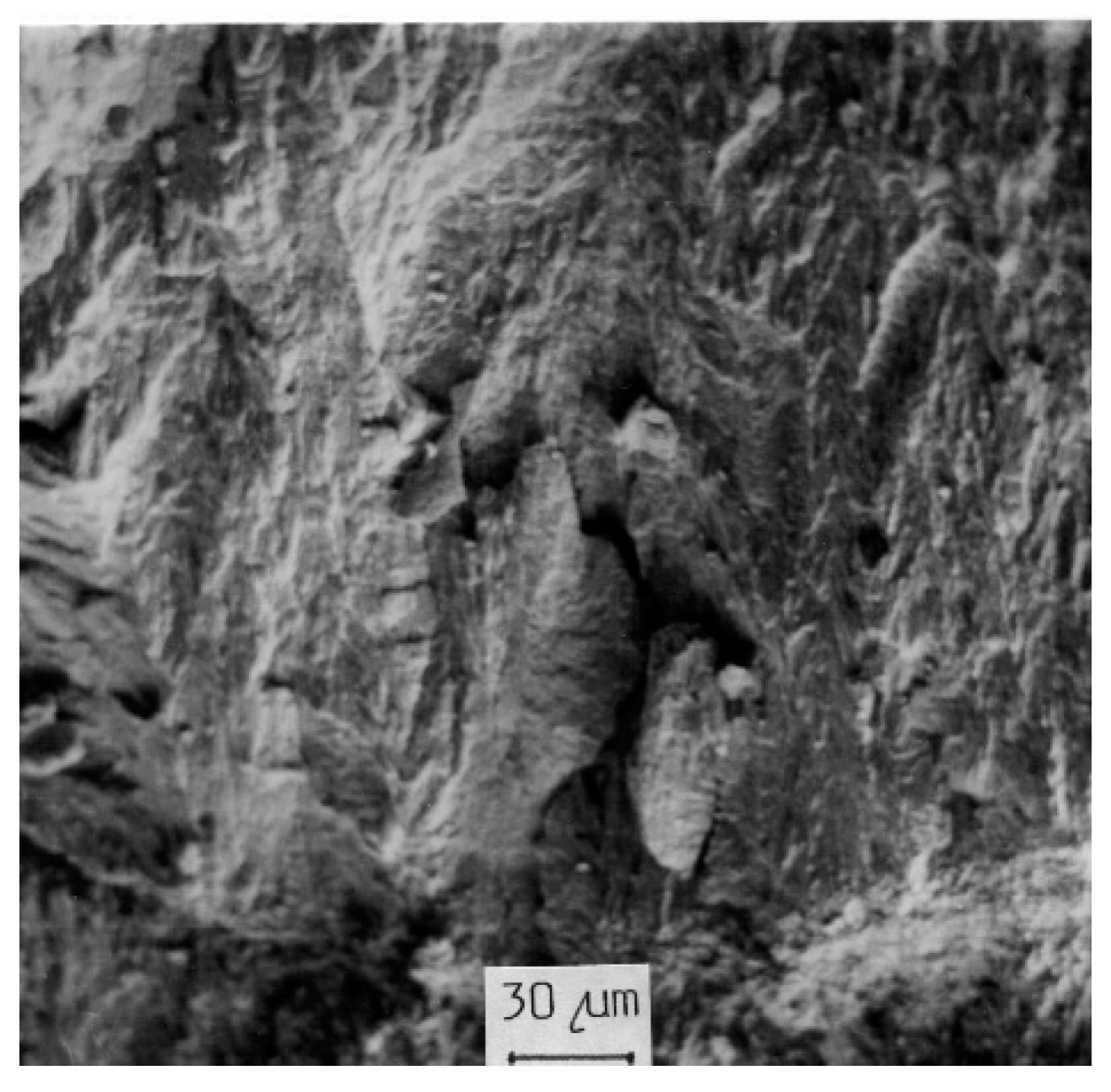
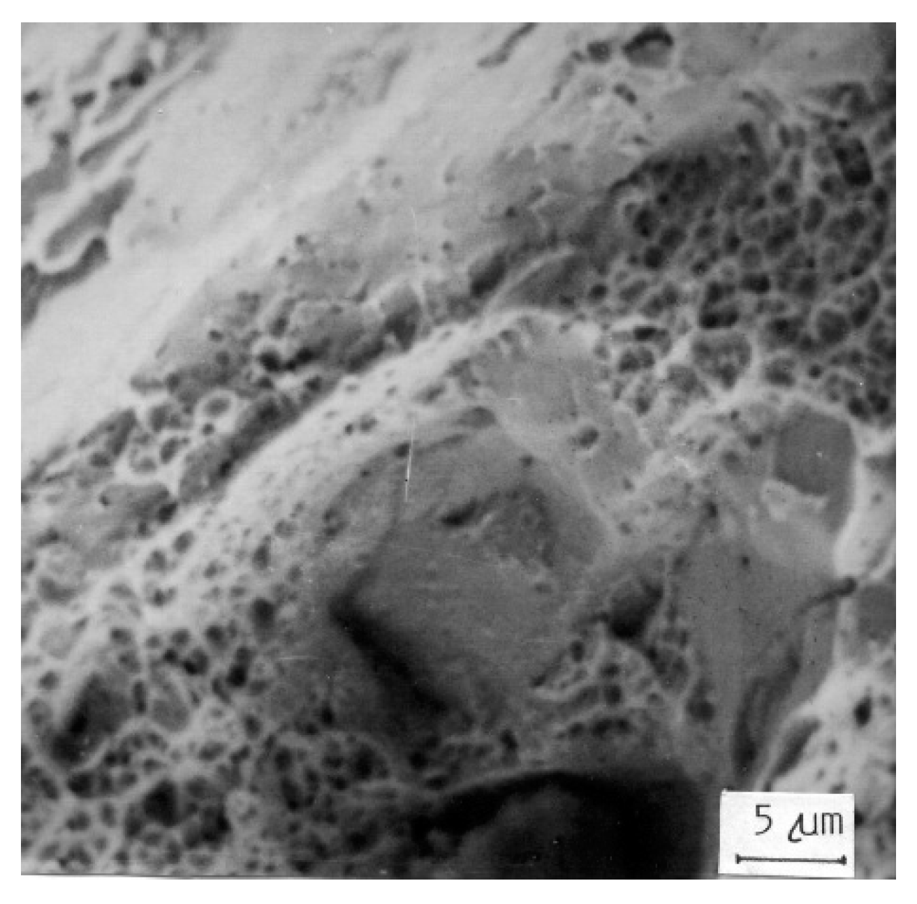
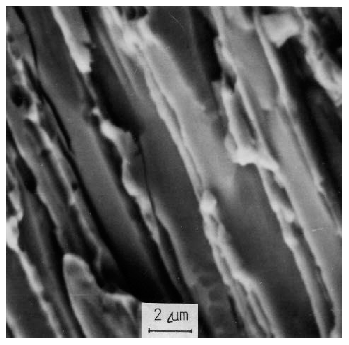
The fracture surfaces of claddings of E 518 B obtained for the purpose of studying the mechanism of their formation confirm that the energy demand for their creation is very low. The view of the fracture surface is shown in
Figure 15. Part of the fracture surface consists of decohesive facets without morphological signs of cleaving or ductile failure. Their formation has occurred by the simple separation of the surfaces at the grain borders with minimum energy consumption. A large part of the fracture, however, consists of facets of cleavage decohesion. These are facets formed by the separation of phase boundaries, but the mechanism of their failure is the cleavage,
i.e., low energy. These surfaces are shown in
Figure 16 and are characteristic for the cast state of the cladding without thermal treatment.
Figure 15.
Fracture surface of cladding E 518 B.
Figure 16.
Detail of decohesive failure.
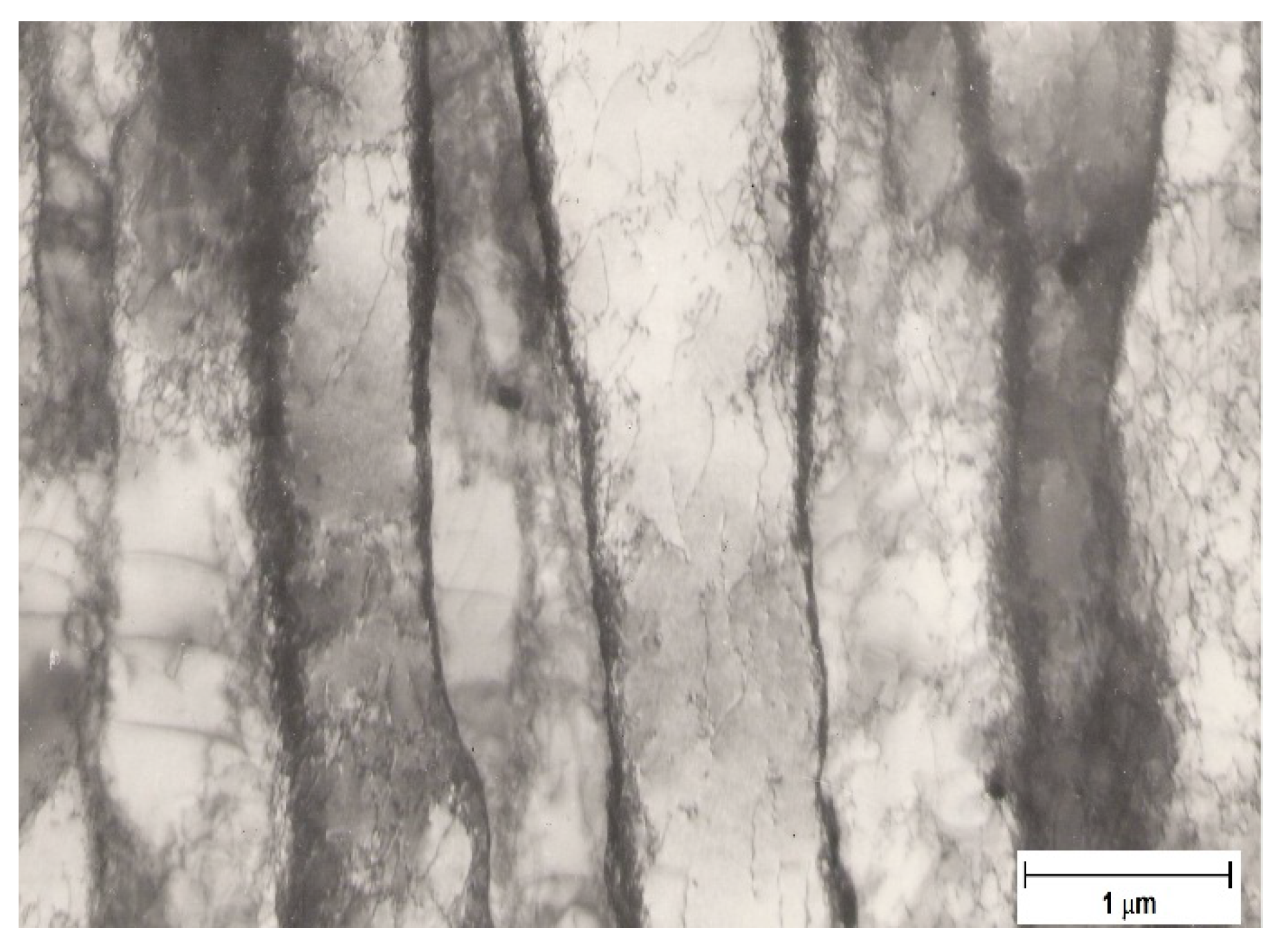
The stated information implies that claddings made by electrode E 508 B have a tough bainitic matrix dispersely reinforced by a carbidic phase, as shown in
Figure 17. This symbiosis of the matrix and disperse carbidic reinforcement optimizes the abrasive wear resistance. The structure has a high density of dislocations whose movement is intensively stopped by the disperse phase, as shown in
Figure 18. Plastic deformation thus requires high stress for the movement of the dislocations. It is known that the bainitic structures with the same chemical compositions optimize mechanical properties,
i.e., at high levels of strength (hardness) they retain adequate ductility.
Figure 17.
Bainitic matrix containing carbides.
Figure 18.
Dislocations in bainitic matrix.
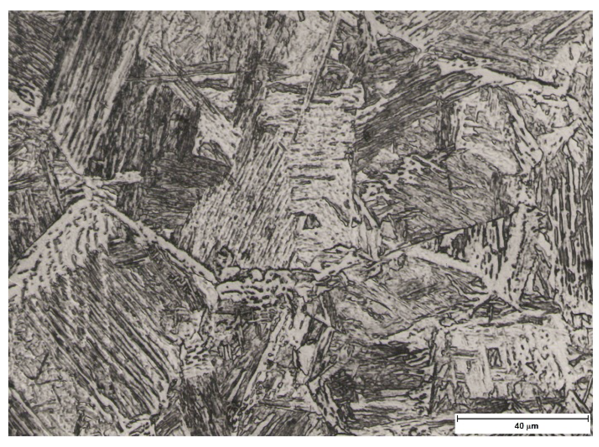
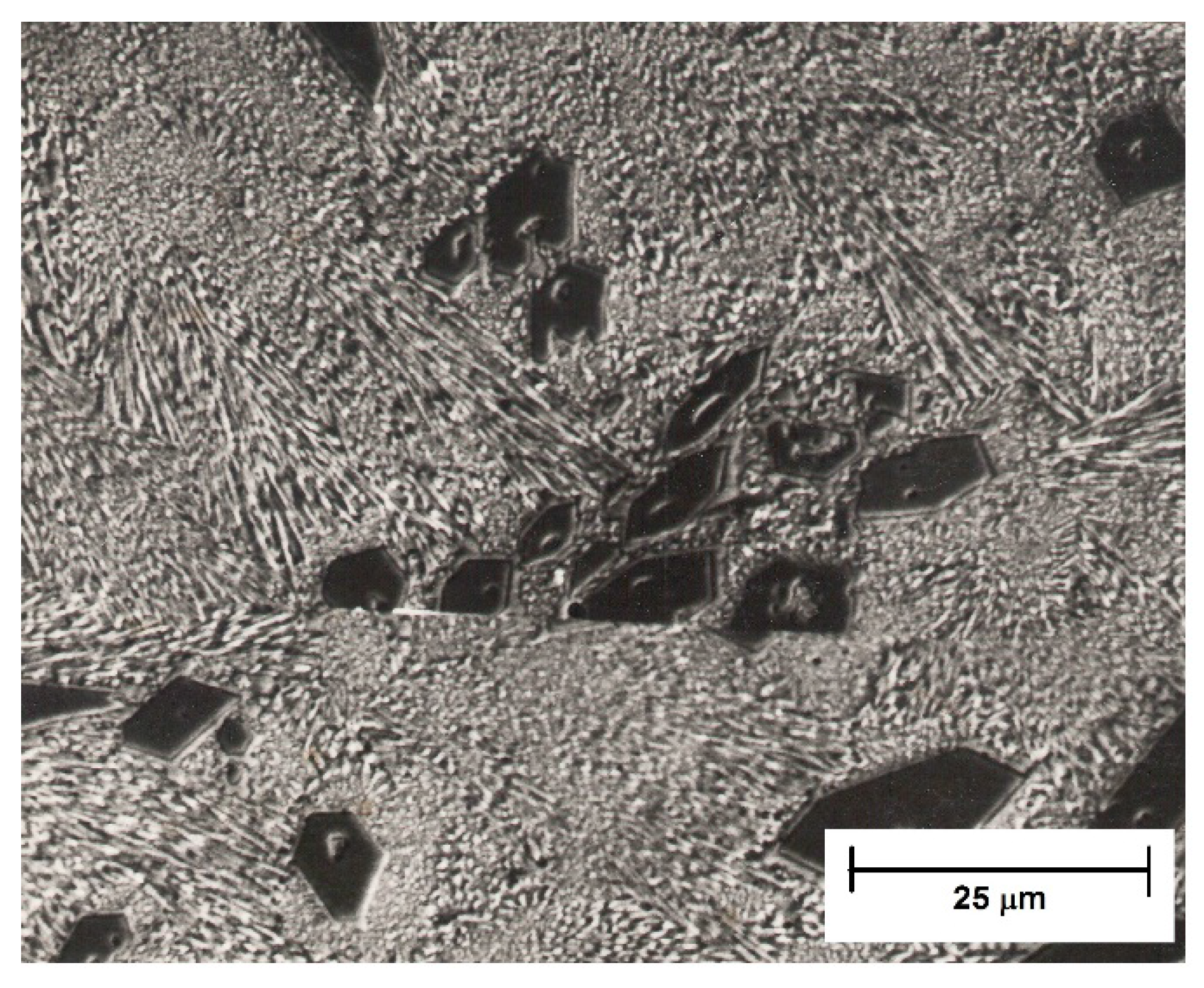
The structure of claddings made by electrode E 518 B is ledeburitic due to the high content of carbon and the high content of chrome. There are primary as well as secondary carbides present in the structure, morphologically formed massively as well as dispersely, a shown in
Figure 19. The dislocation state is high, represented mainly by anchored dislocations.
Figure 19.
Carbides in ledeburitic structure.
Although the material is high strength (hard), it has a small reserve of plastic deformation, and therefore it is brittle. The low strength of the grain boundaries is also added to these properties. It can therefore be concluded that the cohesive strength of the boundaries and subboundaries is significantly lower than the strength of the matrix. The material separation is realized by the decohesion of particles and the separation by the cleaving mechanism.


