Article

Temperature-Dependent Helium Ion-Beam Mixing in an Amorphous SiOC/Crystalline Fe Composite

1
Nebraska Center for Energy Sciences Research, University of Nebraska-Lincoln, Lincoln, NE 68583-0857, USA
2
Department of Nuclear Engineering, Texas A & M University, College Station, TX 77843-3128, USA
3
Department of Mechanical and Materials Engineering, University of Nebraska-Lincoln, Lincoln, NE 68583-0857, USA
4
Nebraska Center for Materials and Nanoscience, University of Nebraska-Lincoln, Lincoln, NE 68588-0298, USA
*
Author to whom correspondence should be addressed.
Metals 2016, 6(11), 261; https://doi.org/10.3390/met6110261
Submission received: 22 August 2016 / Revised: 12 October 2016 / Accepted: 25 October 2016 / Published: 31 October 2016
(This article belongs to the Special Issue Radiation Effects in Metals)

Abstract

:
Temperature dependent He-irradiation-induced ion-beam mixing between amorphous silicon oxycarbide (SiOC) and crystalline Fe was examined with a transmission electron microscope (TEM) and via Rutherford backscattering spectrometry (RBS). The Fe marker layer (7.2 ± 0.8 nm) was placed in between two amorphous SiOC layers (200 nm). The amount of ion-beam mixing after 298, 473, 673, 873, and 1073 K irradiation was investigated. Both TEM and RBS results showed no ion-beam mixing between Fe and SiOC after 473 and 673 K irradiation and a very trivial amount of ion-beam mixing (~2 nm) after 298 K irradiation. At irradiation temperatures higher than 873 K, the Fe marker layer broke down and RBS could no longer be used to quantitatively examine the amount of ion mixing. The results indicate that the Fe/SiOC nanocomposite is thermally stable and tends to demix in the temperature range from 473 to 673 K. For application of this composite structure at temperatures of 873 K or higher, layer stability is a key consideration.

Graphical Abstract

1. Introduction

Ion-solid interactions lead to a significant local rearrangement of atoms [1]. One example is ion-beam mixing during ion irradiation, which is often observed at interfaces of systems containing two or more different materials [2,3,4]. Ion-beam mixing is one of the few measureable quantities that are directly correlated to damage level and has been studied in many solids [5,6,7]. For example, previous experimental results revealed the occurrence of a temperature-independent ion mixing regime at low temperatures and a temperature-dependent ion mixing regime at elevated temperatures [8,9]. At low temperatures (50 K), ion-beam mixing is typically influenced by ballistic collision effects because long-range defect migration is suppressed. Compared with the system which can be driven out of its equilibrium state at low temperatures, mixing at elevated temperatures can drive the system towards equilibrium or an energy favorable state [10]. The ion-beam mixing process is affected by not only irradiation parameters such as ion species, dose, and temperature, but also materials properties including heat of mixing and cohesive energy [7,11]. This is evidenced by significant ion-beam mixing behavior differences in two solid systems (Au on Cu and W on Cu), which have nearly an identical atomic number, atomic mass, and atomic density [12]. After irradiation under similar conditions, W and Cu are barely mixed but Au and Cu are well intermixed [13]. The reason for the dramatic difference is that thermodynamics affect the mixing processes. The Au/Cu system, which has negative heat of mixing, is easy to intermix. While the W/Cu system has positive heat of mixing and tends to demix. For two solid systems with negative heat of mixing, the ion-beam mixing behavior can often be observed by methods such as transmission electron microscope (TEM) and Rutherford backscattering spectrometry (RBS). In some instances, alloy compounds may form at the intermixed interface. In contrast, thermodynamic effects can dominate the mixing processes in two solids systems with a positive heat of mixing; the mixing rate in these system is significantly lower, and irradiation temperature can play a crucial role in the observed amount of ion-beam mixing. Therefore, the ion-beam mixing behaviors of different solid systems can be used to investigate their interface stability and physical properties [6,14].
In this study, the amorphous silicon oxycarbide (SiOC)/crystalline-Fe system was chosen for two main reasons. First, amorphous SiOC possesses high crystallization temperatures (excess of 1300 °C), good oxidation, and creep resistance, making it a promising candidate for usage under extreme conditions [15,16,17,18,19]. As a new kind of irradiation tolerant material, recent studies show that amorphous SiOC retained its amorphous microstructure after both He and Kr irradiation from room temperature to 600 °C, with damage levels up to 20 displacements per atom (dpa) [20,21]. These findings suggest that amorphous SiOC alloys are radiation-indifferent; within an envelope of irradiation conditions, radiation-induced damage anneals out as fast as it is created.
Second, in order to serve in extreme irradiation environments, amorphous SiOC can be combined with a crystalline metal component to improve its mechanical properties and heat conductivity [22,23,24]. One important question about this composite combination is whether the amorphous SiOC/crystalline metal interface is stable during irradiation. In this work, α-Fe was selected as the metal constituent of the composite and was chosen as a surrogate for ferritic-martensitic steel.
Previous work has examined the promising thermal and radiation tolerant properties of this composite [25,26]. The ion-beam mixing behavior and stability of the Fe/SiOC composite has been investigated under 1 MeV Kr irradiation at 50 K, room temperature, 423 K, and 573 K: a temperature-independent mixing regime is observed at low temperature and temperature-dependent demixing is observed at elevated temperatures [27]. Although heavy ion (Kr) mixing of this Fe/SiOC composite has been examined, how this composite responds during light ion-beam mixing and higher temperatures remains unknown. Studying the higher temperature response is motivated by the fact that the design of generation IV nuclear reactor requires an understanding of the material’s behavior at temperatures higher than 573 K [28,29]. Therefore, the interface stability between amorphous SiOC and crystalline Fe was examined by He ion irradiation at temperatures ranging from 298 to 1073 K. The main aim of the present work was to investigate the interface stability of Fe/SiOC composite under light ion irradiation over a wide range of temperatures. A systematic evaluation of these variables will allow for an easier translation to reactor environments.

2. Materials and Methods

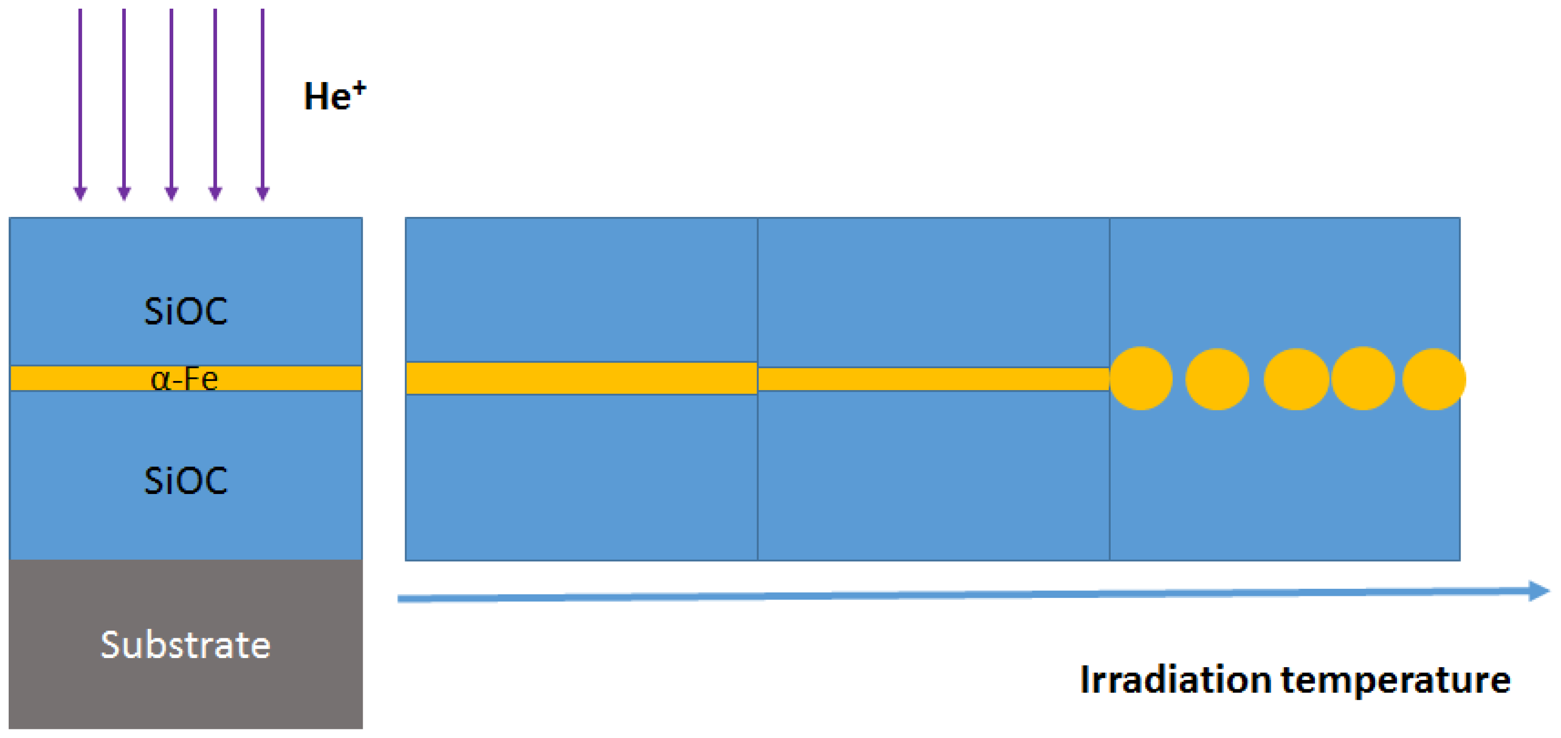
2.1. Marker Specimen Preparation

In this work, Si (100) with a 300 nm SiO2 surface oxide was used as the substrate for subsequently deposited films. Magnetron sputtering was used to prepare the marker specimen where one Fe layer is embedded between two amorphous SiOC layers. The Fe marker layer (7.2 ± 0.8 nm) was prepared near the mid-planes of the specimens (SiOC/Fe/SiOC, 200/7/200 nm). A base pressure of 7.5 × 10⁻⁶ Pa or lower was obtained prior to depositions. The typical Ar partial pressure used to deposit both Fe and SiOC layers was ~0.65 Pa. The amorphous SiOC layers were synthesized from radio frequency (RF) co-sputtering SiC and SiO2 targets at room temperature. As is typical in metal layer sputter deposition, direct current (DC) magnetron sputtering was used to prepare the α-Fe marker layer.

2.2. Ion Irradiation and Rutherford Backscattering Spectrometry (RBS) Experiment

The marker specimens were irradiated by using 120 keV He ions at 298, 473, 673, 873, and 1073 K. The ion irradiations were carried out with an average beam current of 9 microamps (μA). Samples, 1 cm × 1 cm in dimension, were masked so that only half the sample was exposed to the ion beam and the masked part of the sample only experienced thermal heating. For irradiations at temperatures above 298 K, both the thermal and irradiated portions of the samples experienced the same thermal history. Heating to 1073 K was controlled manually. Samples were attached to a hot stage with conductive Ag glue, where the heat stage acted as a heat sink. Temperature readings from thermal couplers (OMEGA Engineering, Inc., Norwalk, CT, USA) attached to the heat stage surface was used to monitor and control heating, through power adjustment to a light bulb contained inside the stage. The temperature measurements through thermal couplers were further calibrated with an infrared camera (FLIR Systems, Wilsonville, OR, USA) which showed good agreement. For irradiation at room temperature, no cooling was applied, and temperatures of samples were slightly increased but stayed constant at about 308 K. For irradiation at an elevated temperature, the heating power was automatically adjusted to include the effect from beam heating. The overall temperature fluctuations under all irradiation conditions were less than 5 K. RBS was carried out using 2 MeV He with a 1 mm × 1 mm beam spot. A semiconductor detector (Ortec, Oak Ridge, TN, USA) with a 20 keV energy resolution was positioned at a scattering angle of 160° away from the beam incident direction. In addition, the samples were tilted 60° (towards the detector) to improve resolution of the Fe marker layer.

2.3. Stopping and Range of Ions in Matter (SRIM) Simulation and Microstructure Characterization

All cross-sectional TEM specimens were prepared by conventional dimple, grinding, and polishing, followed by an ion milling process. A low energy (3.5 keV) and a low angle (5°) were used to minimize the ion milling damage in sample preparation. The microstructure of SiOC/Fe/SiOC marker specimens before and after irradiation was characterized by a Tecnai G2 F20 microscope (Field Electron and Ion Co., Hillsboro, OR, USA) with an operation voltage of 200 keV. The microstructure of marker specimen after pure heat treatment was also examined. Depth-dependent damage and defect concentration profiles were calculated by the Stopping and Range of Ions in Matter (SRIM)-2008 using the ion distribution and quick calculation of damage option [30]. The displacement energies for Fe was taken as 40 eV. The recoil distribution of Si and Fe elements at the Fe/SiOC interface were simulated by using the detailed calculation with the full damage cascades option.

3. Results

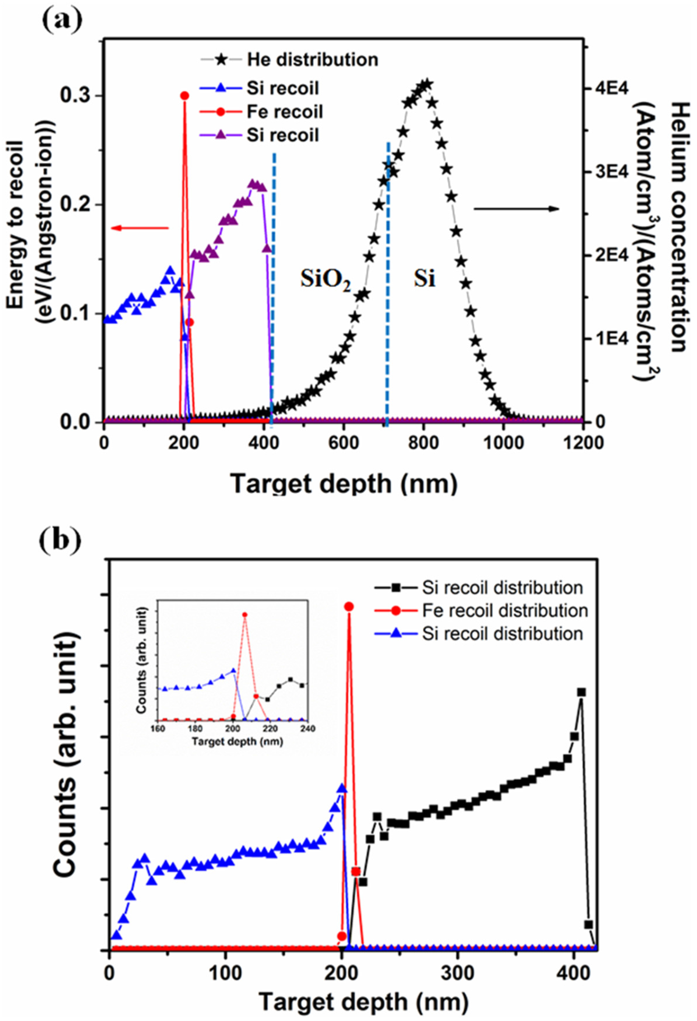
3.1. Stopping and Range of Ions in Matter (SRIM) Simulation

To examine the light ion irradiation stability of the Fe/SiOC interface, 120 keV He ions were selected for the irradiation of marker samples at 298, 473, 673, 873, and 1073 K. Figure 1a presents the SRIM simulation of the Helium implantation distribution and energy-to-recoil profile as a function of target depth. Because most of the helium ions came to rest in the SiO2/silicon substrate, the Fe/SiOC interface only experienced ion irradiation with no He implantation. An Fe layer with a thickness of 7.2 ± 0.8 nm is sandwiched between two amorphous SiOC layers with thicknesses of 200 nm. An estimate of the ballistic mixing was made with SRIM using a sample represented by SiOC/Fe/SiOC (200/7/200 nm). The Si and Fe recoil distribution profiles at the two Fe/SiOC interfaces are presented as Figure 1b. The inset is the magnified recoil distribution at the interface region, which suggests ~10 nm of forward recoil intermixing and 5 nm back recoil intermixing.

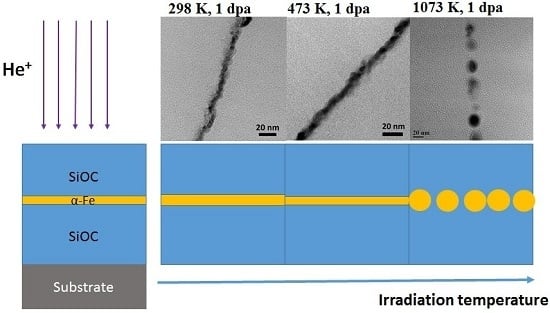
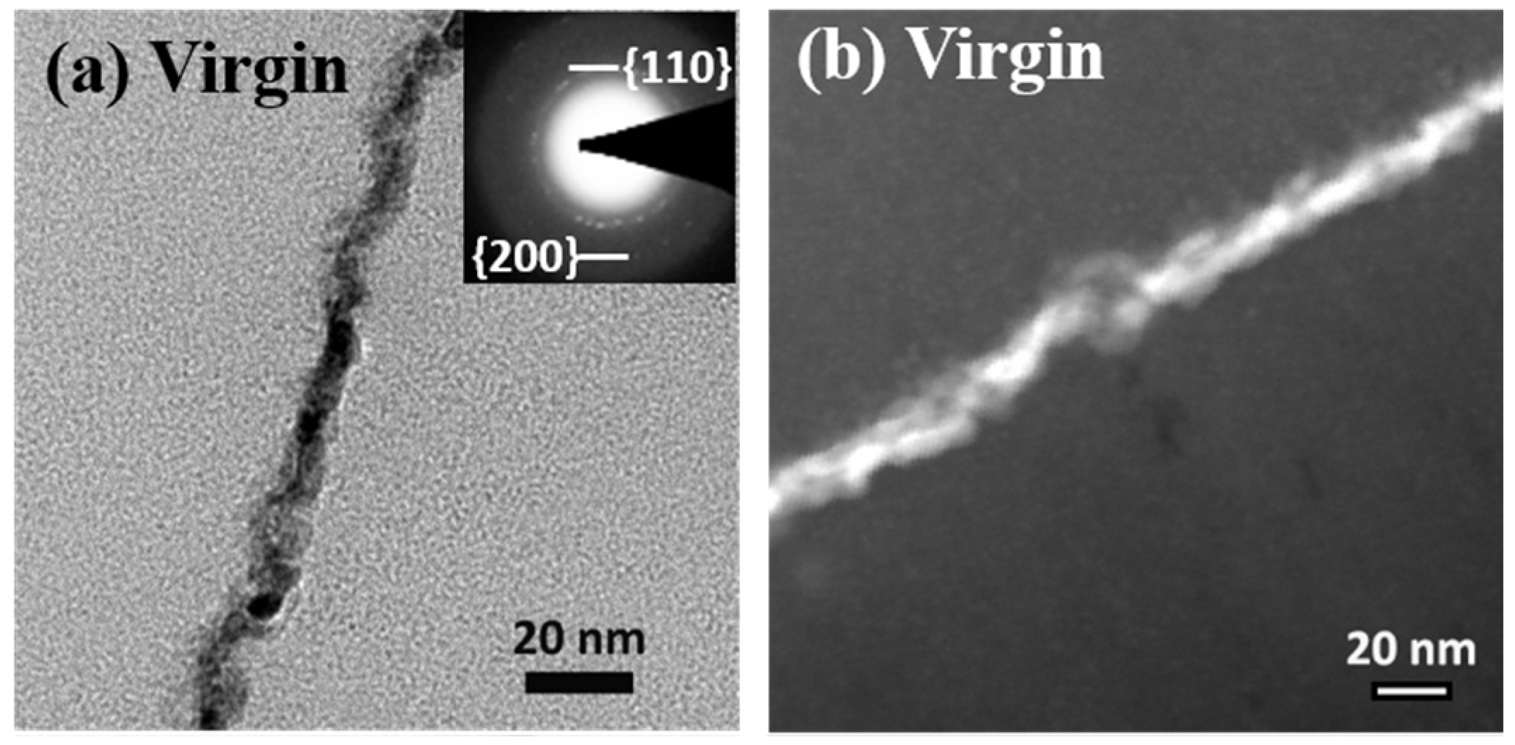
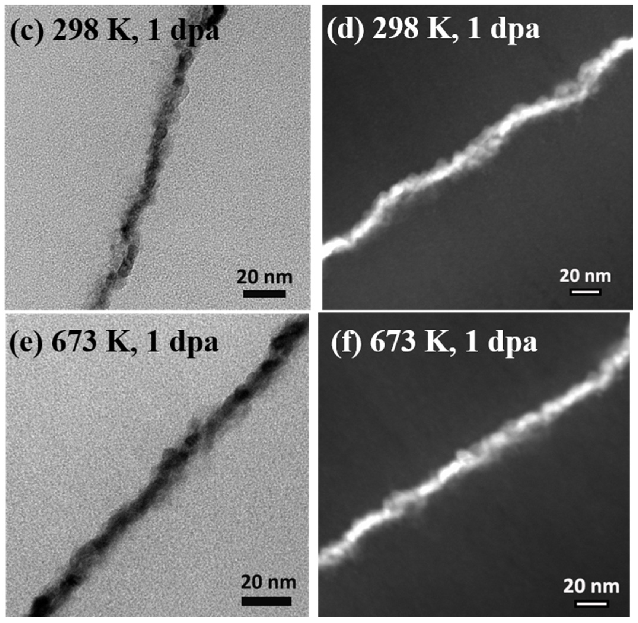
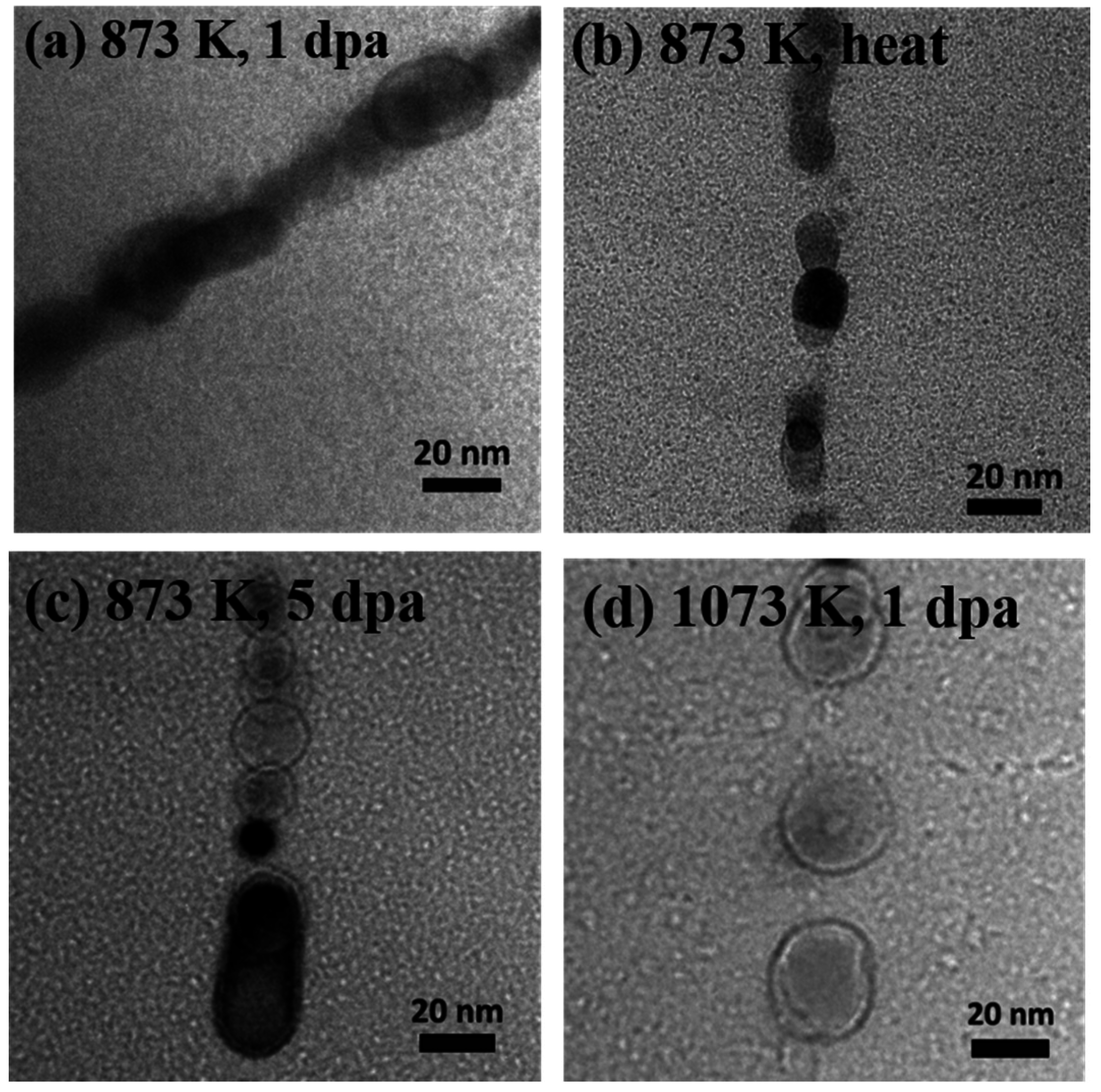
3.2. Analysis of Microstructure before and after Irradiation
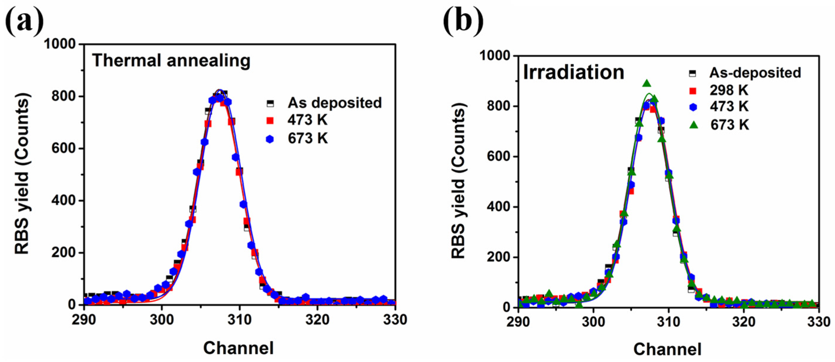
Figure 2a shows the typical cross-sectional bright-field TEM micrograph of a marker specimen before He irradiation where one Fe layer is in between two amorphous SiOC layers. The micrograph shows clear interfaces and the as-deposited SiOC layers exhibit uniform contrast, while the 7.2 ± 0.8 nm thick Fe marker layer shows a typical columnar structure. The selective area diffraction (SAD) pattern of the marker sample (insets of Figure 2a) exhibits a diffuse halo around the central beam and a weak diffraction pattern with similar interval spacing. The results indicate the amorphous nature of the SiOC layers and the body-centered cubic (BCC) structure of the Fe marker layer.
To investigate the light ion radiation stability of the Fe/SiOC interface over a wide range of temperatures, He irradiations were performed at 298, 473, 673, 873, and 1073 K. The typical microstructure evolutions of the marker samples after irradiation at 298 and 673 K with 1 dpa irradiation are presented as Figure 2c,e, respectively. The average thickness of the Fe marker layer expands slightly from 7.2 ± 0.8 nm to 9.7 ± 1.2 nm after 298 K irradiation (Figure 2c). This observation is consistent with heavy ion irradiation (Kr) irradiation results that showed slight layer broadening after room temperature irradiation [27]. Compared with the simulated recoil distribution of Fe, which indicates ~10 nm of forward intermixing and 5 nm back recoil intermixing, the actual extent of layer broadening is smaller after 298 K irradiation. It is interesting to note that the marker layer thickness after 673 K irradiation (Figure 2e) is 7.0 ± 0.9 nm, which is almost the same as that of the as-deposited specimen. In order to clearly show the 2 nm average thickness change in the Fe marker layers, high resolution scanning transmission electron microscope (STEM) images of marker specimens before and after 298 and 673 K irradiation are presented as Figure 2b,d,f, respectively. Compared with the as-deposited marker sample and the marker sample after 673 K irradiation, the sample after 298 K irradiation exhibits several small ion-beam mixing regions. These findings suggest that a certain amount of ion-beam mixing occurred after 298 K irradiation. In general, as an ion penetrates the interface between two different solids, nuclear and electronic energy are deposited into the solid. For He irradiation, the primary processes that take place at the interface include atomic displacements, recoil implantation, and dilute cascades. These processes can result in interatomic mixing between the species of the two solids. The observed layer broadening shown in Figure 2b is the consequence of overlapped localized mixing. When the irradiation temperature is low, the thermal energy for atomic diffusion is small. Therefore, ballistic effects play a significant role in determining the extent of intermixing between Fe and SiOC atoms. As the irradiation temperature increases, kinetics are sufficient to allow chemical driving forces to come into play, and the mixed regions are able to back-segregate if the heat of mixing in that system is positive.
One of the most important features observed after 1 dpa irradiation at 873 K is that significant layer broadening occurs and pinch off sites start to appear in the marker layer (Figure 3a). Similar observations can also be seen for marker layers that experience pure thermal annealing at 873 K, which is shown in Figure 3b. These results suggest that irradiation temperature plays a crucial role in layer stability. In general, layer stability depends on the ratio of average grain size to layer thickness (d/h) [31,32]. The critical d/h value is determined by grain-boundary energies and interface energies between components. Previous work shows that high d/h values result in layer instability. In this SiOC/Fe/SiOC system (200/7/200 nm), the 7 nm thin marker layers undergo breakdown, limiting the stability temperature range for such a thin layer. In addition, increased irradiation damage (5 dpa, Figure 3c) and a higher irradiation temperature (1073 K, Figure 3d) lead to rapid evolution from a discontinuous layered structure to an equiaxed grain microstructure. This process results in rapid spheroidization of the marker layers and the minimization of system energy. One solution to this problem is to increase the thickness of the marker layer.

3.3. RBS Results

To quantify the amount of ion mixing between Fe and SiOC under He irradiation at different temperatures, RBS measurements were conducted for these marker samples before and after irradiation at different temperatures. The marker specimen were also examined after pure equivalent thermal annealing. The RBS yield of marker specimen after thermal annealing and irradiation are present in Figure 4a,b. Because layer breakdown takes place after 873 and 1073 K irradiation, RBS data after these conditions cannot be used to quantify the amount of ion mixing, therefore, these results are not shown in Figure 4. In this study, we take standard derivation (σ) from the Gaussian fitting of the RBS data as a measure of the spreading of the marker layer. The irradiation-induced spreading after thermal annealing and irradiation is determined by the change of variance [7].
σirr2 = σafter2 − σbefore2
Table 1 shows the calculated layer spreading for marker layers before and after pure thermal annealing and irradiation at different temperatures. The results are consistent with the TEM findings presented in Figure 2; a small amount of ion mixing is observed in the marker specimen after RT irradiation, and a radiation-enhance demixing process takes place at 473 and 673 K. The enhanced atomic mobility due to irradiation plus thermal energy drive the Fe/SiOC system to a more energetically favorable state. This is also evidenced by the observed grain growth at the Fe marker layer after 473 or 673 K irradiation.
Figure 5 summarizes the overall trend for He ion mixing over a wide range of temperatures from 298 to 1073 K. A ballistic mixing regime is apparent at low temperature and a demixing regime is observed at elevated temperature. At temperatures higher than a critical temperature, the layered structure breaks down. To determine the ion mixing process at temperatures higher than 873 K, a thicker marker layer is required to overcome the limitation of layer instability.

4. Conclusions

In summary, no ion-beam induced mixing is observed at the Fe/SiOC interface after 473 and 673 K irradiation; on the contrary, a very trivial amount of ion-beam mixing (~2 nm) was presented after RT irradiation. The results indicate a positive heat of mixing in the Fe/SiOC system. When the irradiation temperature reaches 873 K or higher, layer thickness controls stability. These findings provide information on how the SiOC/Fe amorphous-ceramic/crystalline-metal system behaves under ion irradiation over a wide range of temperatures. The data can be used to understand how amorphous/crystal interfaces influence irradiation tolerance and aid in the potential design of such composites for service in extreme harsh environments.

Acknowledgments

We acknowledge financial support from the Department of Energy (DoE) Office of Nuclear Energy, Nuclear Energy Enabling Technologies, award DE-NE0000533. The research was performed in part in the Nebraska Nanoscale Facility: National Nanotechnology Coordinated Infrastructure and the Nebraska Center for Materials and Nanoscience, which are supported by the National Science Foundation under Award ECCS: 1542182, and the Nebraska Research Initiative.

Author Contributions

Qing Su performed the experiment and wrote the paper. Lloyd Price carried out the ion irradiation and RBS measurements under the supervision of Lin Shao. Michael Nastasi supervised the entire project. All authors commented on the manuscript.

Conflicts of Interest

The authors declare no conflict of interest.

References

  1. Matteson, S.; Nicolet, M.A. Ion Mixing. Annu Rev. Mater. Sci. 1983, 13, 339–362. [Google Scholar] [CrossRef]
  2. Perez, A.; Abonneau, E.; Fuchs, G.; Treilleux, M.; Mchargue, C.J.; Joslin, D.L. Ion-Beam Mixing of Metal Ceramic Interfaces. Nucl. Instrum. Methods Phys. Res. B 1992, 65, 129–138. [Google Scholar] [CrossRef]
  3. Nordlund, K.; Ghaly, M.; Averback, R.S. Mechanisms of ion beam mixing in metals and semiconductors. J. Appl. Phys. 1998, 83, 1238–1246. [Google Scholar] [CrossRef]
  4. Nastasi, M.; Hung, L.S.; Mayer, J.W. Phase Formation by Ion-Beam Mixing in Ni/Al, Pd/Al, and Pt/Al Bilayers. Appl. Phys. Lett. 1983, 43, 831–833. [Google Scholar] [CrossRef]
  5. Averback, R.S. Fundamental-Aspects of Ion-Beam Mixing. Nucl. Instrum. Methods Phys. Res. B 1986, 15, 675–687. [Google Scholar] [CrossRef]
  6. Paine, B.M.; Averback, R.S. Ion-Beam Mixing—Basic Experiments. Nucl. Instrum. Methods Phys. Res. B 1985, 7–8, 666–675. [Google Scholar] [CrossRef]
  7. Nastasi, M.; Mayer, J.W. Ion-Beam Mixing in Metallic and Semiconductor-Materials. Mater. Sci. Eng. R Rep. 1994, 12, 1–52. [Google Scholar] [CrossRef]
  8. Rehn, L.E.; Okamoto, P.R. Recent Progress in Understanding Ion-Beam Mixing of Metals. Nucl. Instrum. Methods Phys. Res. B 1989, 39, 104–113. [Google Scholar] [CrossRef]
  9. Dereus, R.; Vredenberg, A.M.; Voorrips, A.C.; Tissink, H.C.; Saris, F.W. Critical-Temperatures for Radiation Enhanced Diffusion and Metastable Alloy Formation in Ion-Beam Mixing. Nucl. Instrum. Methods Phys. Res. B 1991, 53, 24–34. [Google Scholar] [CrossRef]
  10. Fu, C.C.; Torre, J.D.; Willaime, F.; Bocquet, J.L.; Barbu, A. Multiscale modelling of defect kinetics in irradiated iron. Nat. Mater. 2005, 4, 68–74. [Google Scholar] [CrossRef]
  11. Cheng, Y.T.; Vanrossum, M.; Nicolet, M.A.; Johnson, W.L. Influence of Chemical Driving Forces in Ion Mixing of Metallic Bilayers. Appl. Phys. Lett. 1984, 45, 185–187. [Google Scholar] [CrossRef]
  12. Wang, Z.L.; Westendorp, J.F.M.; Saris, F.W. Laser and Ion-Beam Mixing of Cu-Au-Cu and Cu-W-Cu Thin-Films. Nucl. Instrum. Methods Phys. Res. 1983, 209, 115–124. [Google Scholar] [CrossRef]
  13. Westendorp, H.; Wang, Z.L.; Saris, F.W. Ion-Beam Mixing of Cu-Au and Cu-W Systems. Nucl. Instrum. Methods Phys. Res. 1982, 194, 453–456. [Google Scholar] [CrossRef]
  14. Bolse, W. Mechanisms of ion beam induced atomic mixing in solids. Mater. Sci. Eng. A 1998, 253, 194–201. [Google Scholar] [CrossRef]
  15. Soraru, G.D.; Suttor, D. High temperature stability of sol-gel-derived SiOC glasses. J. Sol-Gel Sci. Technol. 1999, 14, 69–74. [Google Scholar] [CrossRef]
  16. Soraru, G.D.; Dallapiccola, E.; DAndrea, G. Mechanical characterization of sol-gel-derived silicon oxycarbide glasses. J. Am. Ceram. Soc. 1996, 79, 2074–2080. [Google Scholar] [CrossRef]
  17. Harshe, R.; Balan, C.; Riedel, R. Amorphous Si(Al)OC ceramic from polysiloxanes: Bulk ceramic processing, crystallization behavior and applications. J. Eur. Ceram. Soc. 2004, 24, 3471–3482. [Google Scholar] [CrossRef]
  18. Rouxel, T.; Massouras, G.; Soraru, G.D. High temperature behavior of a gel-derived SiOC glass: Elasticity and viscosity. J. Sol-Gel Sci. Technol. 1999, 14, 87–94. [Google Scholar] [CrossRef]
  19. Rouxel, T.; Soraru, G.D.; Vicens, J. Creep viscosity and stress relaxation of gel-derived silicon oxycarbide glasses. J. Am. Ceram. Soc. 2001, 84, 1052–1058. [Google Scholar] [CrossRef]
  20. Nastasi, M.; Su, Q.; Price, L.; Santana, J.A.; Chen, T.; Balerio, R.; Shao, L. Superior radiation tolerant materials: Amorphous silicon oxycarbide. J. Nucl. Mater. 2015, 461, 200–205. [Google Scholar] [CrossRef]
  21. Su, Q.; Cui, B.; Kirk, M.A.; Nastasi, M. Cascade effects on the irradiation stability of amorphous SiOC. Philos. Mag. Lett. 2016, 96, 60–66. [Google Scholar] [CrossRef]
  22. Su, Q.; Price, L.; Shao, L.; Nastasi, M. Dose dependence of radiation damage in nano-structured amorphous SiOC/crystalline Fe composite. Mater. Res. Lett. 2016, 4, 48–54. [Google Scholar] [CrossRef]
  23. Su, Q.; Price, L.; Santana, J.A.C.; Shao, L.; Nastasi, M. Irradiation tolerance of amorphous SiOC/crystalline Fe composite. Mater. Lett. 2015, 155, 138–141. [Google Scholar] [CrossRef]
  24. Odette, G.R.; Alinger, M.J.; Wirth, B.D. Recent developments in irradiation-resistant steels. Annu. Rev. Mater. Res. 2008, 38, 471–503. [Google Scholar] [CrossRef]
  25. Su, Q.; Jian, J.; Wang, H.; Nastasi, M. Thermal Stability of Amorphous SiOC/Crystalline Fe Composite. Philos. Mag. 2015, 34, 3876–3887. [Google Scholar] [CrossRef]
  26. Su, Q.; Cui, B.; Kirk, M.A.; Nastasi, M. In situ observation of radiation damage in nano-structured amorphous SiOC/crystalline Fe composite. Scr. Mater. 2016, 113, 79–83. [Google Scholar] [CrossRef]
  27. Su, Q.; Wang, F.; Cui, B.; Nastasi, M. Temperature-dependent ion-beam mixing in amorphous SiOC/crystalline Fe composite. Mater. Res. Lett. 2016, 4, 198–203. [Google Scholar] [CrossRef]
  28. Zinkle, S.J.; Was, G.S. Materials challenges in nuclear energy. Acta Mater. 2013, 61, 735–758. [Google Scholar] [CrossRef]
  29. Zinkle, S.J.; Busby, J.T. Structural materials for fission & fusion energy. Mater. Today 2009, 12, 12–19. [Google Scholar]
  30. Ziegler, J.F.; Biersack, J.P. Littmark, the Stopping and Range of Ions in Solids; Pergamon Press: New York, NY, USA, 1985. [Google Scholar]
  31. Lewis, A.C.; Josell, D.; Weihs, T.P. Stability in thin film multilayers and microlaminates: The role of free energy, structure, and orientation at interfaces and grain boundaries. Scr. Mater. 2003, 48, 1079–1085. [Google Scholar] [CrossRef]
  32. Josell, D.; Carter, W.C.; Bonevich, J.E. Stability of multilayer structures: Capillary effects. Nanostruct. Mater. 1999, 12, 387–390. [Google Scholar] [CrossRef]
Figure 1. (a) Stopping and Range of Ions in Matter (SRIM) simulation of He and energy to recoil profile as a function of target depth. Blue dotted lines present the interfaces between different layers; (b) Simulated Si and Fe recoil distribution by 120 keV He irradiation. The inset is the magnified recoil distribution at the interface region.
Metals 06 00261 g001
Figure 2. Typical cross-sectional bright-field transmission electron microscope (TEM) micrographs of marker specimen (a) before and after (c) 298 K and (e) 673 K, 1 dpa irradiation. The high resolution scanning transmission electron microscope (STEM) images of these specimens are shown as (b), (d), and (f), respectively.
Metals 06 00261 g002aMetals 06 00261 g002b
Figure 3. The microstructural evolution of marker specimen after (a) 873 K 1 dpa irradiation and (b) pure 873 K thermal annealing, showing layer breakdown after either thermal annealing or irradiation. The discontinuous layered structure evolved to an equiaxed grain microstructure after (c) 873 K 5 dpa and (d) 1073 K 1 dpa irradiation.
Metals 06 00261 g003
Figure 4. Rutherford backscattering spectrometry (RBS) yield of Fe marker layer (a) after different temperatures annealing and (b) different temperatures irradiation. A Gaussian function is used to fit these data.
Metals 06 00261 g004
Figure 5. Schematic illustration of sample geometry and structural evolution of marker layer as a function of irradiation temperature.
Metals 06 00261 g005
Table 1. The layer spreading after thermal annealing and different temperature irradiation. A positive number indicates layer spreading; a negative number suggests layer sharpening.
SpecimensLayer Spreading after Thermal Annealing (nm)Layer Spreading after 1 dpa Irradiation (nm)
298 K02.5 ± 0.4
473 K1.0 ± 0.3−2.0 ± 0.3
673 K1.0 ± 0.3−2.6 ± 0.6

