Article

Tribocorrosion Study of Ordinary and Laser-Melted Ti6Al4V Alloy

by
Danillo P. Silva
1,
Cristina Churiaque
2,
Ivan N. Bastos
1 and
José María Sánchez-Amaya
2,*
1
Instituto Politécnico, Universidade do Estado do Rio de Janeiro, Rua Bonfim, 25, Nova Friburgo, Rio de Janeiro 8.265-570, Brazil
2
Laboratorio de Ensayos, Corrosión y Protección, Departamento de Ciencia de los Materiales, Ingeniería Metalúrgicay Química Inorgánica, Escuela Superior de Ingeniería, Universidad de Cádiz, Avenida de La Universidad de Cádiz, Puerto Real, Cádiz 11519, Spain
*
Author to whom correspondence should be addressed.
Metals 2016, 6(10), 253; https://doi.org/10.3390/met6100253
Submission received: 7 August 2016 / Revised: 13 October 2016 / Accepted: 18 October 2016 / Published: 24 October 2016
(This article belongs to the Special Issue Intermetallics 2016)

Abstract

:
Titanium alloys are used in biomedical implants, as well as in other applications, due to the excellent combination of corrosion resistance and mechanical properties. However, the tribocorrosion resistance of titanium alloy is normally not satisfactory. Therefore, surface modification is a way to improve this specific performance. In the present paper, laser surface-modified samples were tested in corrosion and pin-on-disk tribocorrosion testing in 0.90% NaCl under an average Hertzian pressure of 410 MPa against an alumina sphere. Laser-modified samples of Ti6Al4V were compared with ordinary Ti6Al4V alloy. Electrochemical impedance showed higher modulus for laser-treated samples than for ordinary Ti6Al4V ones. Moreover, atomic force microscopy revealed that laser-treated surfaces presented less wear than ordinary alloy for the initial exposure. For a further exposure to wear, i.e., when the wear depth is beyond the initial laser-affected layer, both materials showed similar corrosion behavior. Microstructure analysis and finite element method simulations revealed that the different behavior between the initial and the extensive rubbing was related to a fine martensite-rich external layer developed on the irradiated surface of the fusion zone.

1. Introduction

Commercially pure titanium and titanium alloys are largely used in different applications, such as biomedical, aerospace, automotive, petrochemical, nuclear, etc. These vast application fields are ascribed to their high mechanical strength, low specific mass, and good corrosion resistance as a consequence of the formation of very stable, continuous, adherent, and protective oxide films on metal surfaces [1,2,3]. Moreover, excellent corrosion resistance and high biocompatibility of titanium alloys in physiological medium make them very adequate for biomedical applications such as dental implants and orthopedic prostheses. Titanium’s ability to form calcium phosphate in vitro biocompatibility tests in simulated body fluid is considered as a good indicator of in vivo success [4,5,6]. However, in prostheses, tribochemical reactions can take place at the stem-bone interface [7]. These reactions occur along with micromotion due to body locomotion, leading to important problems to patients, such as the loosening of the implant, osteolysis, release of metal ions, and wear particles.
Despite the diverse satisfactory properties related to titanium based-alloys, its tribological performance is generally poor [8,9,10]. Tribocorrosion is a highly complex topic, due to an intricate and not well established synergy between mechanical, metallurgical, and electrochemical factors. In this way, in addition to the local electrochemical features of the intermittent passive-active transition in the fretting region, the wear mechanism can be different according to the local interactions between the metal surface and the sliding element. These wear mechanisms are often referred to as abrasive, adhesive, delamination, and oxidative [11], not always being independent nor excluding. For example, the subjacent process, such as the accumulation of dislocations, stress concentration in the metal substrate, as well as scale dependence [12,13,14], can be relevant in the determination of the mode of wear on damaged regions [14]. Therefore, these issues increase the natural complexity of tribocorrosion phenomena.
Several modifications have been reported in the literature on the improvement of titanium surface properties [5,15,16,17,18] by different methods, including laser-assisted methods [10,19,20]. In fact, laser technology can be employed in several industrial processes, comprising welding similar [18] and dissimilar alloys [19], or the modification of surface properties for corrosion resistance improvements [20]. Laser remelting (LR) of Ti6Al4V with appropriate fluence provokes microstructural changes leading to an increase in microhardness without jeopardizing the corrosion resistance [21]. Therefore, the laser-modified surface is expected to improve the wear performance. Thus, the tribocorrosion properties of laser remelted titanium alloys deserve further analysis because of the complexity of interfacial phenomena. In the present work, a laser remelting treatment was applied to Ti6Al4V and tested under tribocorrosion conditions. Then, a comparative study of ordinary and laser-remelted Ti6Al4V alloy was carried out.

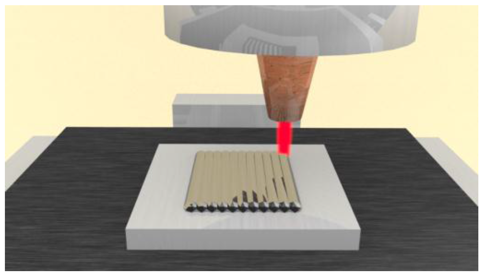
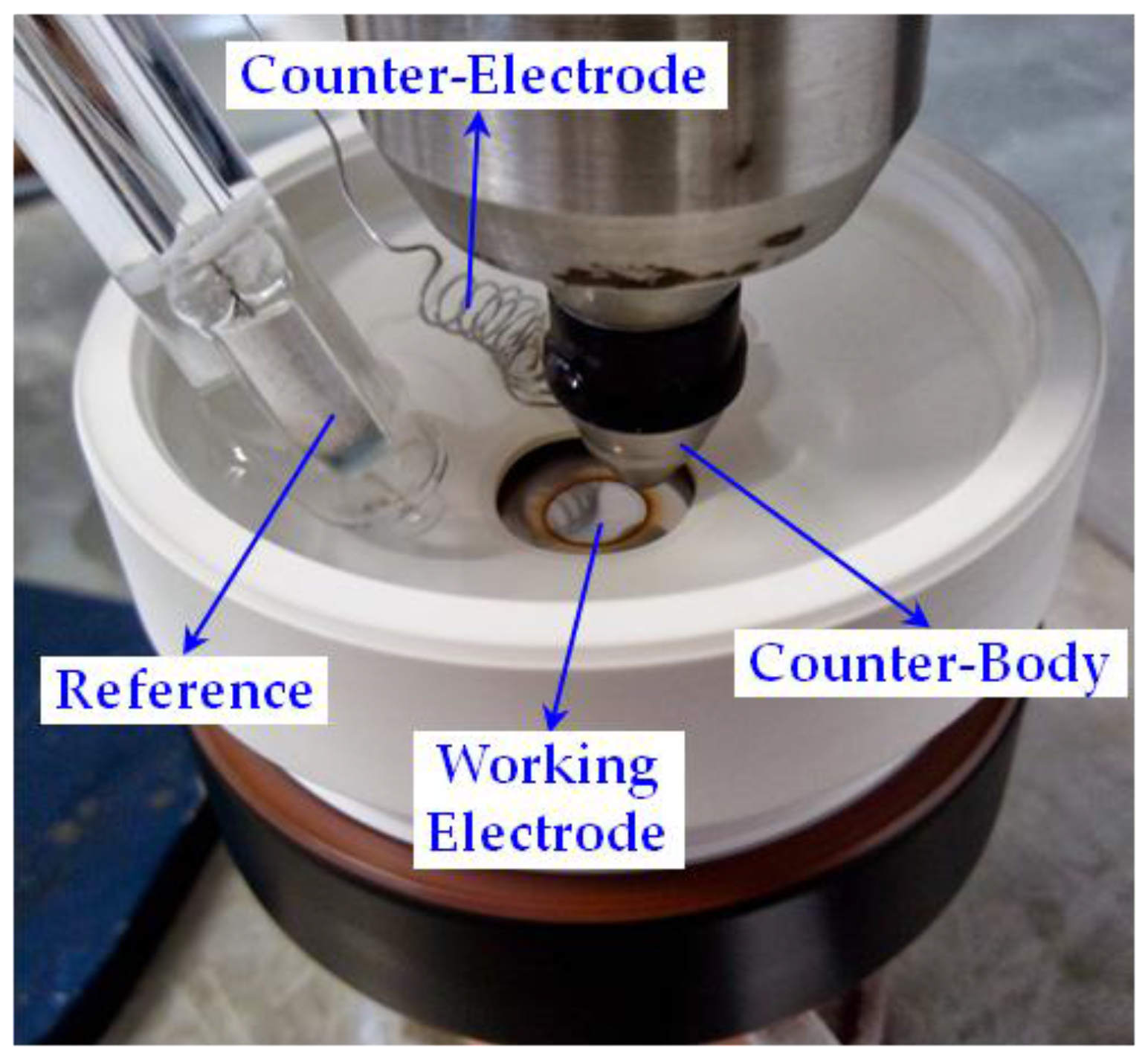
2. Materials and Methods

Samples of Ti6Al4V alloy (grade 5) were used in tribocorrosion testing. The chemical composition is specified in Table 1. Some Ti6Al4V samples were subjected to laser remelting (LR) treatments. Before the laser treatments, the samples were blasted with corundum particle sand cleaned with acetone to homogenize the surface and avoid the possible appearance of defects [22]. A Rofin-Sinar DL028S high power diode laser (Rofin-Sinar, Plymouth, MA, USA) was employed working at the focal distance (69.3 mm from the focusing lens, providing an almost rectangular spot of 2.2 × 1.7 mm2) with 2.0 kW laser power and 1.0 m/min scanning rate. To avoid oxidation, samples were placed in a laboratory-made conditioned chamber during laser treatments, in which argon was injected at a flow rate of 10 L/min. Laser remelting treatments consisted of performing 16 linear parallel laser scans of 30 mm long on Ti6Al4V samples (35 mm × 35 mm × 3 mm). Each scan was separated by 1.5 mm from the previous one to obtain appropriate overlapping. Sixteen seconds was the waiting time between scans to avoid overheating. These treatments allow a remelted area of approximately 30 mm × 26 mm. Figure 1 exhibits a scheme of the setup used to perform the LR treatments. Laser-treated samples were designed as Ti6Al4V-LR, and the base metal denoted as Ti6Al4V-BM. In order to perform the tribocorrosion tests, both Ti6Al4V-LR and Ti6Al4V-BM samples were machined to obtain disks 24 mm diameter. This shape is required to be assembled on the pin-on-disk apparatus [23].
The microstructure and microhardness were evaluated with mounted cross-sections of the samples. Mounted samples were ground, polished (with 0.04 μm colloidal silica suspension, Struers OP-U, Struers, Ballerup, Denmark), etched with Kroll’s reagent freshly prepared in laboratory (6.0 mL HNO3, 2.0 mL HF and filled with distilled water to produce 100 mL of solution) for 15 s, rinsed with distilled water, and carefully dried [21]. Microhardness measurements were obtained with a Duramin microhardness tester from Struers (Struers, Ballerup, Denmark), following the standard UNE-EN-ISO 6507-1:2006 [24]. The mechanical load employed was 19.61 N (HV 2), for 19 s.
A finite element method (FEM) has been used to simulate the laser remelting process in Ti6Al4V alloy. The approach estimates the effect on the Ti6Al4V parts of a moving heat source, whose size and shape has been previously optimized for the employed high power diode laser [25]. SYSWELD software (ESI group, Paris, France) was employed to perform the simulations of single linear laser scans.
Before the tribocorrosion tests, titanium samples were slightly abraded with SiC emery paper to #600, subsequently cleaned with distilled water and alcohol, and dried with blast air. In these tests, 4.00 mm diameter alumina spheres (Sóesferas, São Paulo, Brazil), made according to UNE-EN-ISO 3290-2:2014 [26], were used as the counterpart. Each test was performed with a new alumina sphere, applying a normal load of 2.0 N. This load represents a Herztian pressure of 410 MPa. A pin-on-disk tribometer (Homemade, Nova Friburgo, Brazil) was used with a rotation frequency of 1.25 Hz (75 rotations per minute). A load cell (Alfa Instrumentos, São Paulo, Brazil) measured the friction force.
After each tribocorrosion test, the wear track was analyzed by optical microscopy (Olympus, Tokyo, Japan) and its cross-section profile was acquired by profilometry (roughness tester model SJ-210, Mitutoyo, Kawasaki, Japan). Some worn tracks were also examined by a Nanosurf C3000 atomic force microscope (AFM, Nanosurf AG, Liestal, Switzerland) in intermittent mode contact for samples tested in an initial wear of 10 s exposure.
Corrosion behavior was evaluated by three techniques: open circuit potential (OCP, one hour) electrochemical impedance spectroscopy (EIS), and potentiodynamic polarization curves. Electrochemical tests were performed using a Princeton Applied Research Versastat 3 potentiostat (Advanced Measurement Technology Inc., Oak Ridge, TN, USA). Figure 2 depicts the main parts of the electrochemical cell adapted for tribocorrosion measurements. A saturated calomel electrode (SCE) was used as the reference. A platinum wire was used as a counter-electrode in both polarization curves and EIS measurements. All tests were carried out in a three-electrode cell containing 0.90 wt. % NaCl aqueous solution at room temperature. The measured solution pH was 6.5. An electrolyte volume of 150 mL was used in the tribocorrosion cell, and 250 mL for the corrosion tests.
To perform the electrochemical impedance spectroscopy, a frequency range from 10 kHz to 10 mHz with a sine wave perturbation of 8 mV was used under potentiostatic control at the corrosion potential. The EIS diagrams were fitted by the equivalent electric circuit, as shown in Figure 3, as successfully used for Ti6Al4V in previous studies [21,27]. Echem Analyst 6.11® (Gamry Instruments Incorporated, Warminster, PA, USA) was the software used to fit the EIS diagrams. The constant phase element (CPE) was used to fit the impedance of the equivalent circuit. A simplex procedure was used to perform the complex nonlinear regression to obtain the impedance parameters. Re represents the electrolyte resistance; Q and α are the CPE parameter and exponent, respectively; and Rp is the polarization resistance. Mechanical load application was employed for 600 s and, subsequently, the electrochemical measurement was performed. Electrochemical impedance was acquired before, during, and after load application.
Polarization curves were performed at a 0.50 mV/s scan rate and swept from 0.4 V below the open circuit potential (−0.4 V vs. OCP) up to 2 V above the saturated calomel electrode (2.0 V vs. SCE). Mechanically-loaded and non-loaded samples were tested in polarization. Load application was employed for 600 s and, subsequently, the measurement was performed. Friction force was sampled at 10 Hz and the data shown is the averaged signal.

3. Results and Discussion

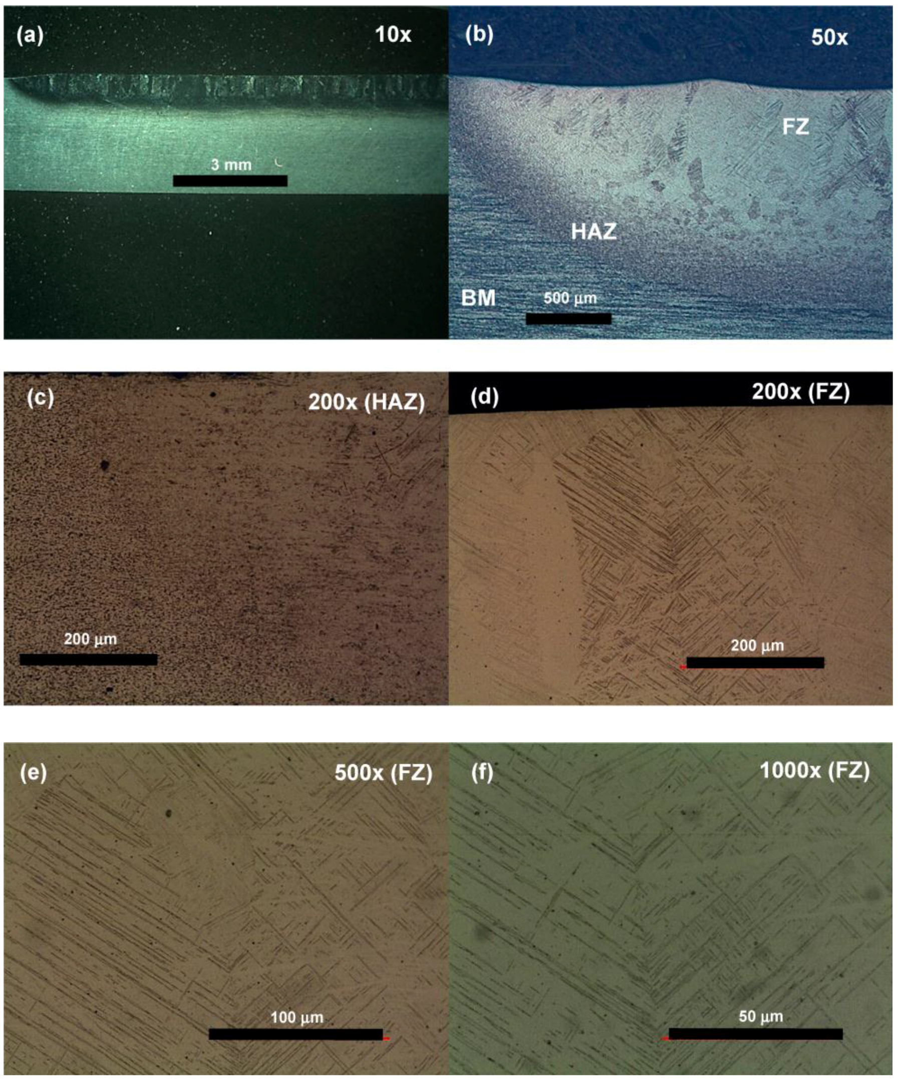
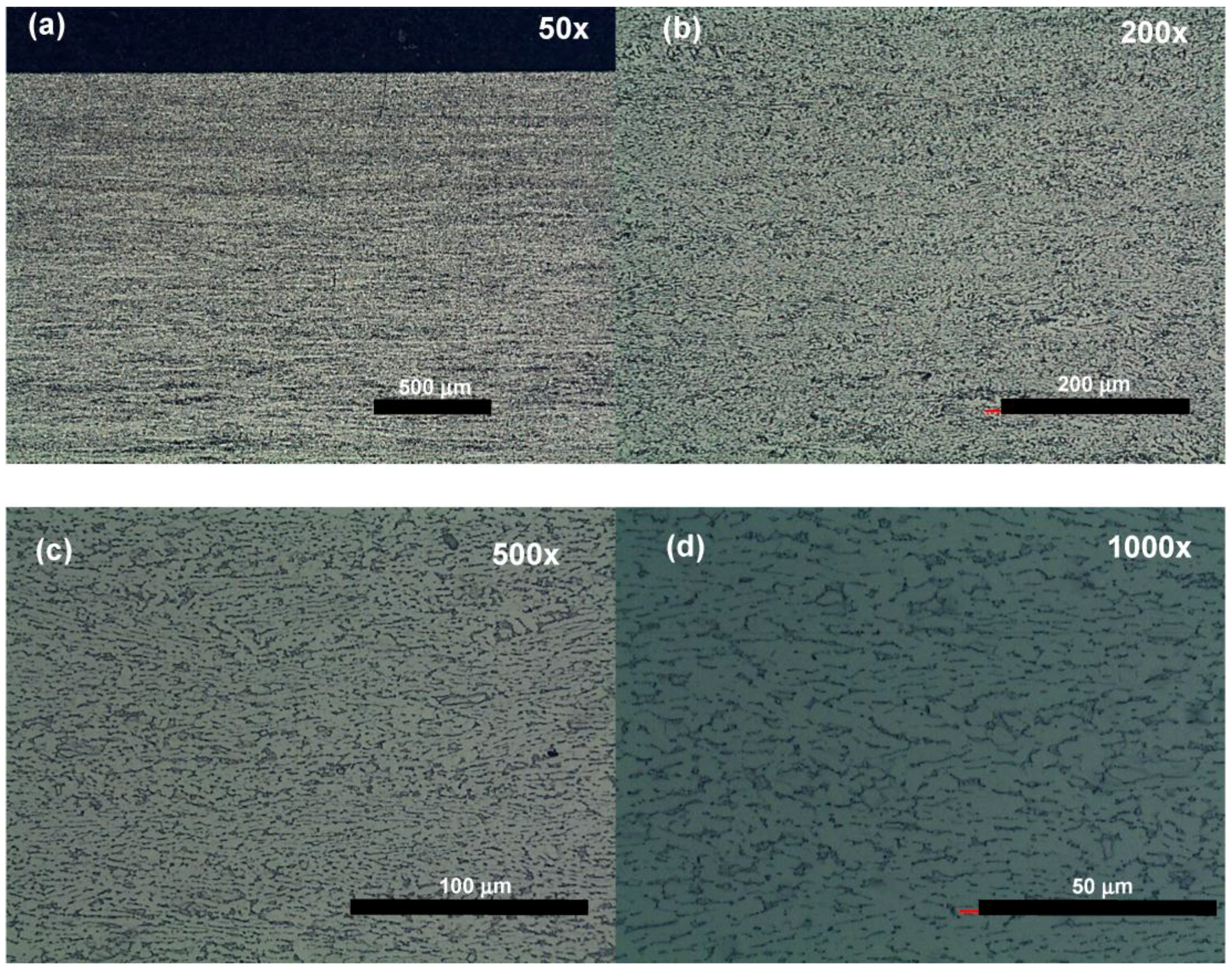
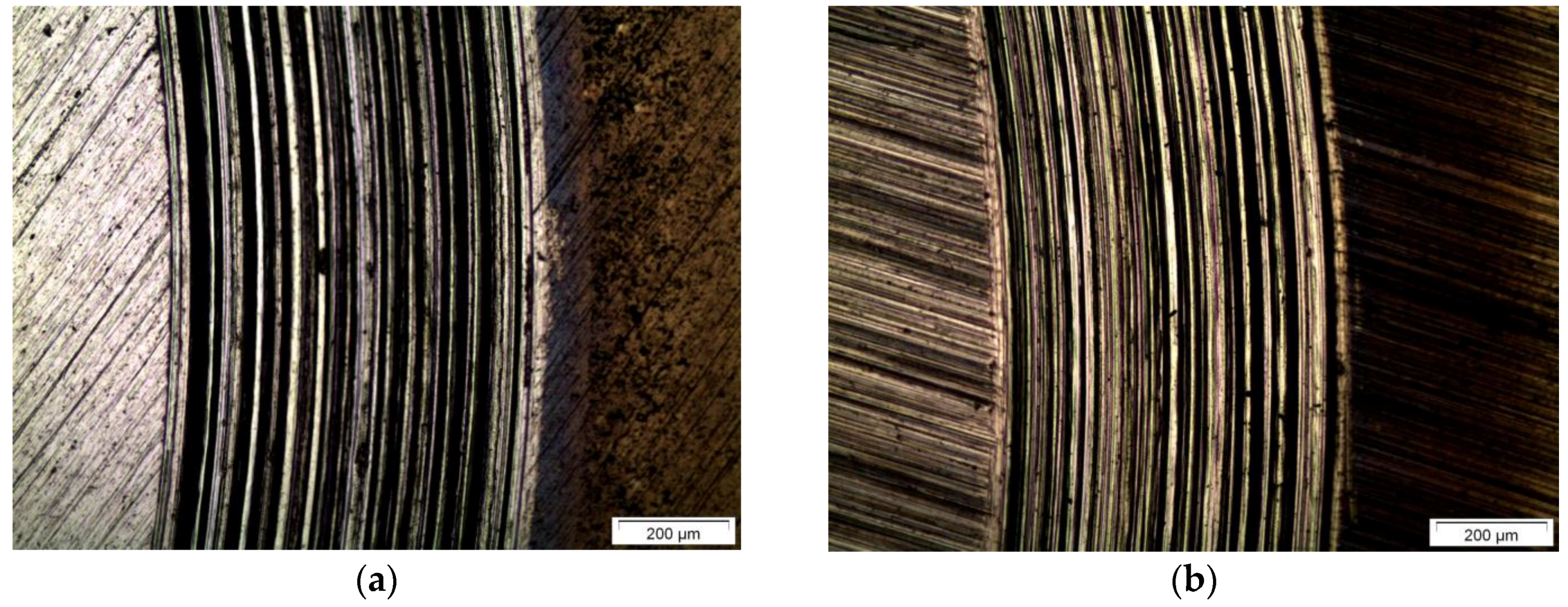
3.1. Microstructure and Microhardness

Figure 4 shows the microstructure of the base metal (Ti6Al4V-BM). It presents a microstructure characterized by two phases: equiaxed α grains with intergranular β particles, in good agreement with previous studies [18,21]. The microstructure of Ti6Al4V samples remelted by laser treatment (Ti6Al4V-LR) is quite different than that of Ti6Al4V-BM, as depicted in Figure 5. Ti6Al4V-LR showed in Figure 5 exhibits a laser-treated region of about 1 mm in depth, from which 700 µm approximately corresponds to the fusion zone (FZ). A detailed examination reveals that FZ microstructure presents acicular martensite (α′), as depicted in Figure 5e,f. This phase is generated as a consequence of the high heating and cooling rates of the laser processing. Its hardness is reported to be between 50 and 100 HV harder than the typical α + β microstructure observed in the Ti6Al4V base metal [21]. Martensite alpha prime phase (α′) generally has high hardness, but relatively low toughness. The HAZ (heat affected zone) has a microstructural mixture of BM (α + β) and FZ (α′), therefore presenting intermediate hardness values. Mean and standard deviation of Vickers microhardness values measured in Ti6Al4V-BM and at the different zones in Ti6Al4V-LR are reported in Table 2. The values are in good agreement with those previously reported in the literature, being the FZ of Ti6Al4V-LR around 60 HV harder than Ti6Al4V-BM. It is worth noting that BM in the laser-remelted sample is slightly harder than the non-treated material, due to the influence of the laser heat treatment, which is not enough to provoke the phase transformation (then, it remains as α + β) but induces some hardening.
It is interesting focusing on the analysis of the superficial microstructure developed in Ti6Al4V-LR, presented in Figure 6. A thin layer of 8–13 µm is developed from the surface, which seems to be a rich martensitic zone, presenting high microstructural refinement. This acicular martensite is thinner than the one observed at the inner part of the FZ. This thin superficial microstructure is associated with the higher heating and the subsequent higher cooling rate taking place just after the laser treatment, leading to a finer martensite than that formed at the FZ.
Finite element method simulations were carried out to show that the external surface of the irradiated zone reached a higher temperature and higher cooling rate than the inner part of the fusion zone (Figure 7a). In addition, the simulations also confirm that the external surface of the FZ presents a higher martensite content than the inner part of the FZ (Figure 7b). This feature is shown later to have an important influence on the tribocorrosion behavior. This external martensite rich layer presents an average depth of 10 µm of the fusion zone. Taking into account the presence of this thin layer, the tribocorrosion tests were performed both at initial rubbing and also at extensive rubbing, in order to be sensitive to the layer effects on the results.

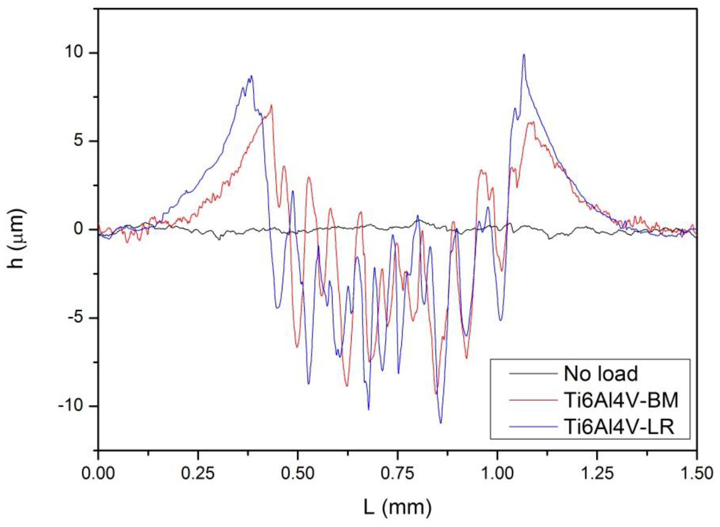
3.2. Tribocorrosion Behavior at Initial Rubbing

Tribocorrosion studies of LR samples have been divided into initial and extensive rubbing, providing the differences aforementioned related to the external martensite-rich thin layer and the inner part of the FZ. The initial rubbing refers to the wear limited to the first instants of rubbing, in which the finer superficial martensite layer could have influence. On the other hand, extensive rubbing studies analyze the effect of severe wear (up to one hour of friction), in which the FZ, or even the base metal is present. This methodology of testing at two rubbing times also allows the study of the layer modification effects on tribocorrosion. As the thin layer can be harder than the HAZ, the damaged (anodic) area might be relatively small for this initial stage of wear.
The first effect of friction evaluated has been noted in the monitoring of the open circuit potential with the initial rubbing, as shown in Figure 8. The open circuit potential after approximately 1800 s exposure is close to −0.45 V vs. SCE, and the steady-state condition can be assumed. Thus, the effect of rubbing on OCP (open circuit potential) can be monitored. When the rubbing (for 2.0 N load) starts, the potential decreases about 0.5 V for the base metal sample (Ti6Al4V-BM) and about 0.4 V for the laser-treated sample (Ti6Al4V-LR). The different potential drops of the samples is thought to be related to their different wear resistance at this initial period of the rubbing. Consequently, the lower potential drop of Ti6Al4V-LR is indicative of its higher wear resistance, surely due to the different superficial microstructure developed in this sample. In fact, the mixed potential presented during sliding is dependent on the anodic (worn)/cathodic (passive) area ratio. Thus, a high ratio gives more negative potential values. Thus, the smaller potential drop of Ti6Al4V-LR suggested a smaller anodic/cathodic area ratio of the laser-treated samples when rubbing is confined in 10 µm of the thin layer. After some minutes of this initial rubbing, the potential behavior of the Ti6Al4V-LR becomes similar to that of Ti6Al4V-BM, most certainly because of the degradation of the superficial rich martensitic layer.
For comparison, the wear track was also evaluated with AFM. The exposure time was limited to 10 s of friction. In fact, there is a clear difference between Ti6Al4V-BM and Ti6Al4V-LR samples (Figure 9). Initial wear is more intense for Ti6Al4V-BM, in which the wear track is deeper than that of LR. As the surface finish is the same, as well as the alumina counter-body, the shallow track of Ti6Al4V-LR samples is thought to be related to the thin superficial α′ microstructure, providing a tribocorrosion resistance increase at the surface. The representative peak to peak height of Ti6Al4V-LR sample is less than 1 µm, being approximately 2 µm for the Ti6Al4V-BM. The counter-body contact occurs at a width of about 0.1 mm, as depicted in Figure 9b,d. For this initial wear, the laser-treated samples resist more damage than non-treated titanium alloy, which is probably related to the thin superficial martensite microstructure (8–13 µm). These findings suggested that the laser treatment increases the wear resistance of titanium alloy, likely caused by the high hardness [21]. Barril et al. [28] have found that for Ti6Al4V/0.9% NaCl system in fretting corrosion, the initial smeared surface is smaller for lower slip amplitude. In the present paper, in addition to the reported slip difference and even the testing (fretting and pin-on-disk tests), the presence of the thin martensite rich layer seems to reduce the wear.

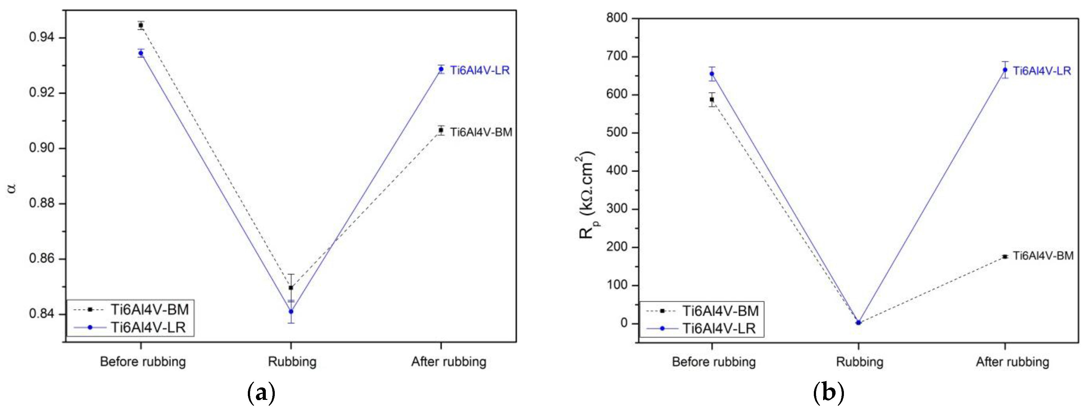
3.3. Tribocorrosion Behavior at Extensive Rubbing

The tribocorrosion tests performed under extensive rubbing are analyzed in this section. Thus, the depth profile of the worn surface reaches the inner part of the FZ, going beyond the external martensite-rich thin layer. The tests were performed for 3600 s without load and, subsequently, 600 s of rubbing at open circuit potential. Polarization curves of Ti6Al4V-BM and Ti6Al4V-LR samples were carried out (Figure 10a) and the effect of applied potential on coefficient of friction was monitored (Figure 10b). In both samples (Ti6Al4V-BM and Ti6Al4V-LR), the corrosion potential decreases from −0.4 V vs. SCE approx. (when no load is applied, Figure 10a) to −0.65 V vs. SCE approx. (when applying the load, Figure 10b). In addition to this decay of potential, the average current density in both samples increases almost two decades when friction is employed. Thus, the average current density increases from 100 nA/cm2 approx. (in non-rubbing polarization curves, Figure 10a) to 10 µA/cm2 approx. (in rubbing polarization curves, Figure 10b). Current scattering under friction is clearly observable. This behavior can be ascribed to the effect of sliding that wears the passive layer of titanium and the subsequent repassivation of the surface.
When polarization curves are analyzed under the no rubbing condition, Ti6Al4V-BM and Ti6Al4V-LR have corrosion potential values around −320 and −420 mV vs. SCE, respectively. Meanwhile, under friction, both samples present corrosion potentials of about −630 mV vs. SCE. The effect of loading in the passivation current densities (measured at 0.0 V vs. SCE) increased, in both samples, from approximately 2 µA/cm2 (no rubbing, Figure 10a) to 90 µA/cm2 (rubbing, Figure 10b). Moreover, the scattering related to the mean current density is negligible without loading (less than 1 µA/cm2), but very high with friction (around 40 µA/cm2). These results have been summarized in Table 3.
The mean coefficient of friction changes very little with the potential, as shown in Figure 10b. Additionally, there is a significant scattering of the current data. This scattering increases with the potential when anodic processes are more intense. In this case, a possible interaction of dissolution on the wear mechanism would be expected, as related in [23]. However, neither a modification of the coefficient of friction, nor a surface feature modification was observed with the applied potential. Wear grooves were observed in ordinary and laser-treated samples, both related to the abrasion wear mechanism. Then, the wear mechanisms do not seem to change, at least to the potential range of Figure 10b. Moreover, adhesion marks were also observed in the tracks of the samples. As mentioned beforehand, when extensive wear is applied, both samples have similar wear, especially close to the corrosion potential. Moreover, the coefficient of friction is higher than 0.25, regardless of the microstructure or potential. In this case, due to the stress distribution, the plastic flow occurs chiefly on the surface, instead of the subsurface layer [13]. This fact augments the importance of the superficial thin layer produced by laser remelting on tribocorrosion behavior.
In Figure 11, the titanium alloy profiles are shown. It can be seen that wear is very similar in depth and width for both materials. However, titanium track profiles have a serrated shape, unlike the stainless steel-alumina pair [23]. Moreover, in certain sites the tracks were observed to be still deeper, but not detected by profilometry due to the narrow contact area. This suggests that the dissolution and/or wear is not uniform in all points of the track. The tracks are depicted in Figure 12 using optical light microscopy. The alumina counter-body has a diameter of 4.0 mm, but the profiles present a serrated shape with approximately 1 mm.
Figure 13 shows the impedance diagrams of titanium alloy samples after an open circuit exposure of 3600 s in Nyquist format. The continuous lines are the fitted response of the equivalent electric circuit with the parameters of Table 4. Both conditions present a high capacitive loop. A capacitive-like loop is normally found in passive alloys. The effect of wear is the reduction of the impedance modulus after the rubbing. However, the impedance of laser samples is slightly superior than that of non-treated surface. The impedance diagrams for base metal are similar to those of Amaya-Vazquez et al. [21], taking into account their lower minimum frequency (1.0 mHz) and the higher open circuit exposure. These factors increased the measured modulus of passive metals. Table 4 shows the adjusted parameters of electrochemical impedance for the circuit of Figure 3.
Two parameters of the impedance equivalent circuit (Figure 3) were depicted in Figure 14. In general, the closer to unity is the alpha, and the higher the Rp, the better corrosion resistance a given surface has. Before the wear, alpha and polarization resistance are similar in BM and LR samples. During rubbing, both parameters decrease strongly, and Rp decays to a few kΩ·cm2, corresponding to the bare surface of the alloys. After the rub, the worn surfaces exhibit diagrams with modulus and phase lower than those before loading. The wear provokes an increase of the Q parameter, as can be noted in Table 4. This increase represents a decay of impedance modulus caused by the damage in the passive film. This damage is also observed in Rp and alpha values that reduce the measured impedance. The alpha reduction (Figure 14a) during rubbing can be related to heterogeneities at the electrode surface caused by the friction and the breakdown of the passive film. With the relief of friction, the alpha almost recovers its previous values.
The CPE circuit has been ascribed to many phenomena, but the roughness can be considered the leading cause of its time dispersion characteristic. We roughly estimated the frequency beyond which the effect of wear roughness are V-shaped grooves on the CPE. We use the findings of [29], specifically Figure 14 of the cited work, to evaluate grosso modo the effect of roughness on the impedance frequency. The roughness factor is (fr = 1/cosθ), where θ represents the angle between the groove and the plane surface. In the present case, the factor was approximate to unity, as follows: From a representative peak from the profile of Figure 11, we evaluate tgθ ≈ 10 μm/50 μm, θ = 11°, and fr ≈ 1 at first approximation. Additionally, assuming that the distance between peaks P is 100 µm, the electrolyte conductivity of 0.90% NaCl is 1.45 mS/cm and the interfacial capacitance is 10 µF/cm2, the roughness affects the impedance above 10 kHz, if the entire electrode has similar finishing. Then, under these assumptions, the effect of wear roughness can be considered as negligible in the measured EIS. The global impedance is evaluated as a result of a parallel connection of impedances from passive and worn surfaces (low impedance). Thus, the impedance diagram mainly expresses the increase of electrochemical activity related to the exposure of bare metal and the passive film, and not the effect of roughness as the profile could suggest. Anyway, the laser-treated samples exhibit better properties than base metal after rubbing, with higher alpha and Rp when compared to the base metal.
Laser peening induces significant residual compressive stress in Ti6Al4V alloy, and a reduction of wear volume of the titanium alloy was also ascribed to the presence of compressive stress [30]. This stress likely occurred in the samples studied in the present work, although it was not measured.

4. Conclusions

The microstructure of ordinary Ti6Al4V (Ti6Al4V-BM) and laser-remelted Ti6Al4V (Ti6Al4V-LR) samples were characterized in 0.90% NaCl at room temperature. Both types of samples were subjected to corrosion (open circuit potential, EIS, polarization curves) and tribocorrosion tests (rubbing on a pin-on-disk tribometer against an alumina sphere). Based on the obtained findings, it is possible to remark the following points:
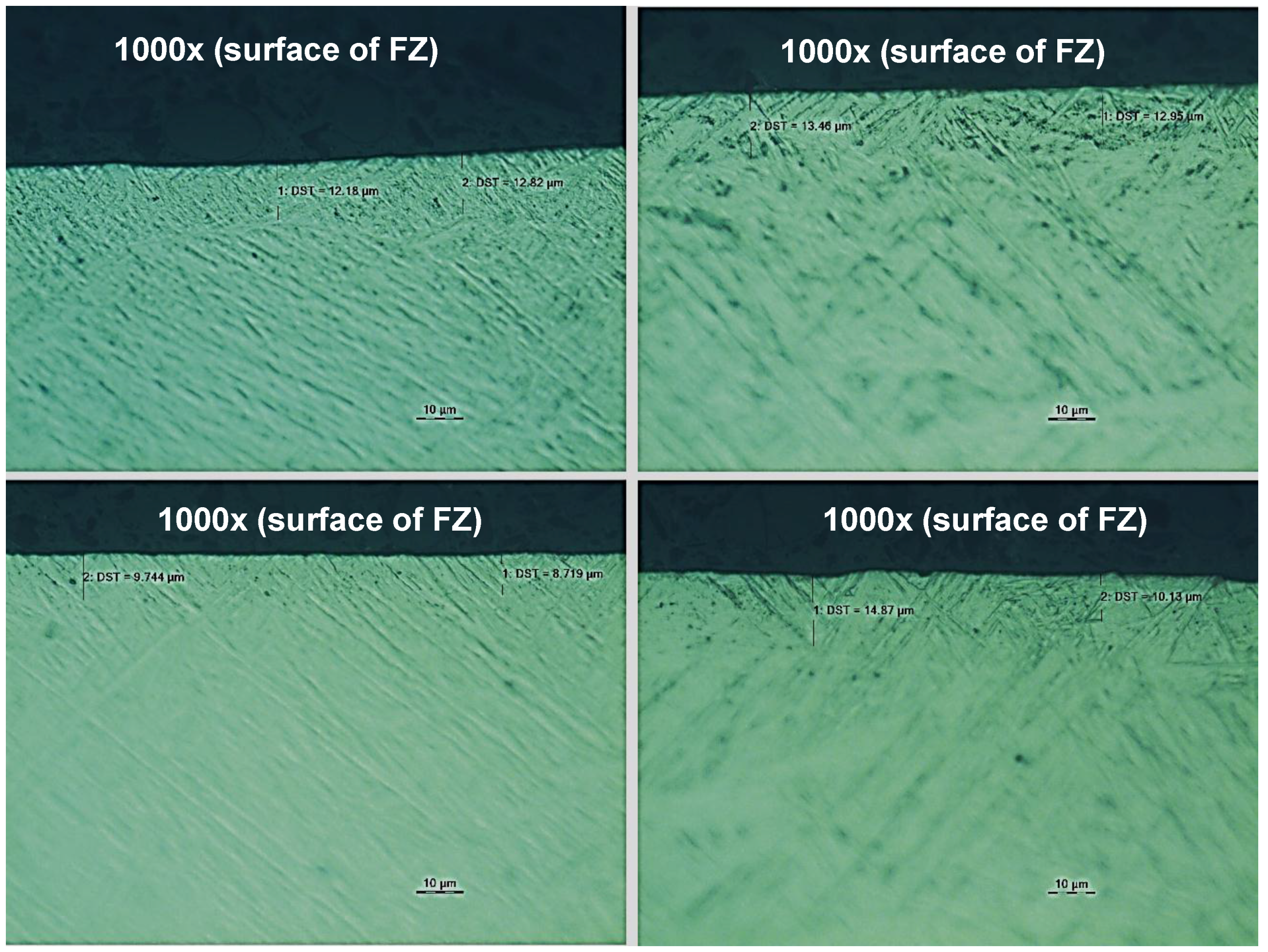
  • Initial rubbing reveals that laser-remelted Ti6Al4V samples present better tribocorrosion resistance (shallower track wear) than ordinary non-treated Ti6Al4V-BM samples. This initial wear improvement is associated with the development of a fine α′ martensitic microstructure on the external surface of the laser samples, with an approximate thickness of 10 µm.
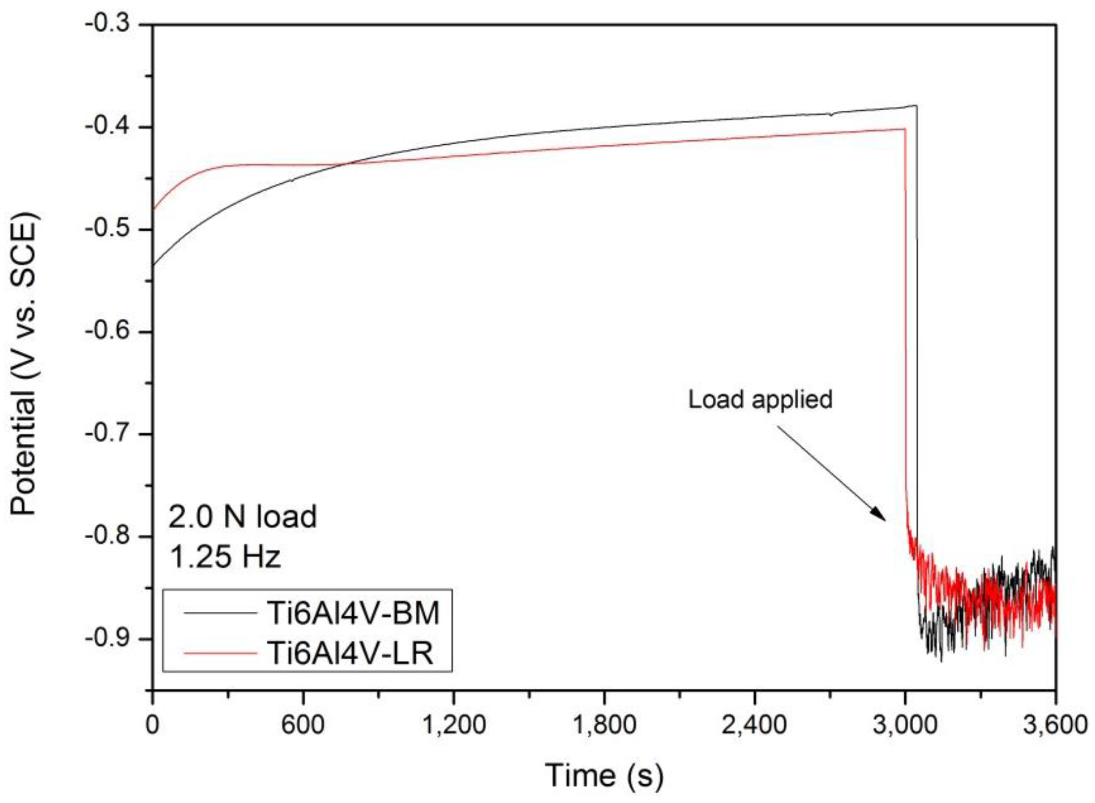
  • Although Ti6Al4V-BM and Ti6Al4V-LR have different microstructures, they showed similar tribocorrosion behavior in extensive rubbing tests.
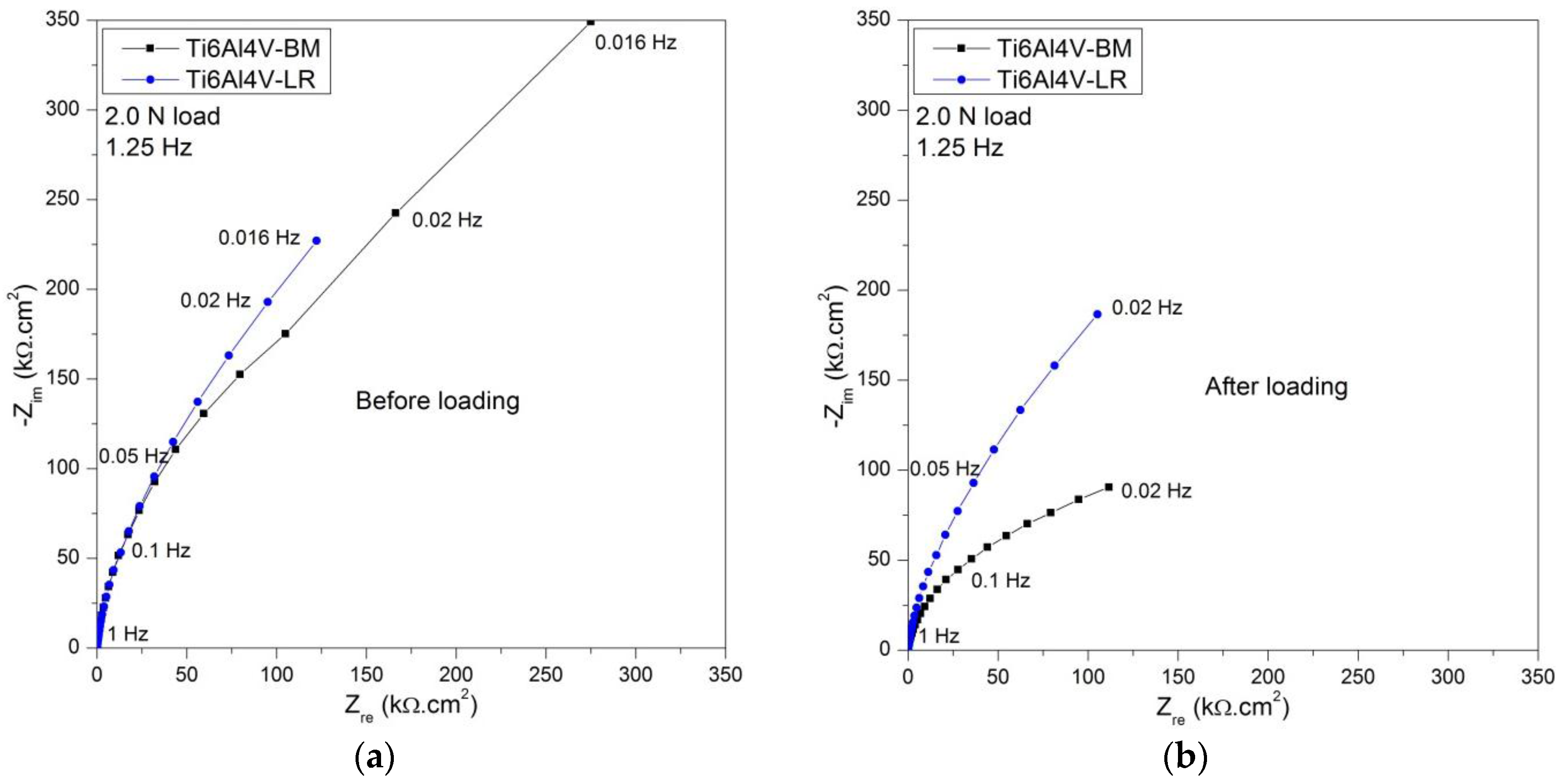
  • Electrochemical impedance diagrams are similar for Ti6Al4V-BM and Ti6Al4V-LR samples during the rubbing. However, after this phase, and without counter-body contact, a higher EIS modulus is observed for the laser-remelted samples.

Acknowledgments

The authors thank the financial support of Faperj (Brazil, E26/110.644/2012), CNPq (Brazil) and Junta de Andalucía (Spain, project SOLDATIA, Ref. TEP 6180).

Author Contributions

I.N.B. conceived the experiments; C.C. performed the FEM simulations; J.M.S.-A. prepared the LR samples; D.P.S. performed the experiments; J.M.S.-A. and I.N.B. analyzed the data; and D.P.S. wrote the paper.

Conflicts of Interest

The authors declare no conflict of interest.

References

  1. Sun, Z.; Annergren, I.; Pan, D.; Mai, T.A. Effect of laser surface remelting on the corrosion behavior of commercially pure titanium sheet. Mater. Sci. Eng. A 2003, 345, 293–300. [Google Scholar] [CrossRef]
  2. Akman, E.; Demir, A.; Canel, T.; Sınmazçelik, T. Laser welding of Ti6Al4V titanium alloys. J. Mater. Process. Technol. 2009, 209, 3705–3713. [Google Scholar] [CrossRef]
  3. Prasad, S.; Ehrensberger, M.; Gibson, M.P.; Kim, H.; Monaco, E.A., Jr. Biomaterial properties of titanium in dentistry. J. Oral Biosci. 2015, 57, 192–199. [Google Scholar] [CrossRef]
  4. Bastos, I.N.; Platt, G.M.; Andrade, M.C.; Soares, G.D. Theoretical study of Tris and Bistris effects on simulated body fluids. J. Mol. Liq. 2008, 139, 121–130. [Google Scholar] [CrossRef]
  5. Resende, C.X.; Dille, J.; Platt, G.M.; Bastos, I.N.; Soares, G.D. Characterization of coating produced on titanium surface by a designed solution containing calcium and phosphate ions. Mater. Chem. Phys. 2008, 108, 429–435. [Google Scholar] [CrossRef]
  6. Kokubo, T.; Takadama, H. How useful is SBF in predicting in vivo bone bioactivity? Biomaterials 2006, 27, 2907–2915. [Google Scholar] [CrossRef] [PubMed]
  7. Runa, M.J.; Mathew, M.T.; Rocha, L.A. Tribocorrosion response of the Ti6Al4V alloys commonly used in femoral stems. Tribol. Int. 2013, 68, 85–93. [Google Scholar] [CrossRef]
  8. Niinomi, M. Mechanical properties of biomedical titanium alloys. Mater. Sci. Eng. A 1998, 243, 231–236. [Google Scholar] [CrossRef]
  9. Vieira, A.; Ribeiro, A.; Rocha, L.; Celis, J.P. Influence of pH and corrosion inhibitors on the tribocorrosion of titanium in artificial saliva. Wear 2006, 261, 994–1001. [Google Scholar] [CrossRef]
  10. Weng, F.; Chen, C.; Yu, H. Research status of laser cladding on titanium and its alloys: A review. Mater. Des. 2014, 58, 412–425. [Google Scholar] [CrossRef]
  11. Landolt, D. Corrosion and Surface Chemistry of Metals, 1st ed.; EPFL Press: Lausanne, Switzerland, 2007. [Google Scholar]
  12. Achanta, S.; Liskiewicz, T.; Drees, D.; Celis, J.-P. Friction mechanisms at the micro-scale. Tribol. Int. 2009, 42, 1792–1799. [Google Scholar] [CrossRef]
  13. Johnson, K.L. Contact mechanics and the wear of metals. Wear 1995, 190, 162–170. [Google Scholar] [CrossRef]
  14. Yamamoto, T.; Fushimi, K.; Habazaki, H.; Konno, H. Depassivation-repassivation behavior of a pure iron surface investigated by micro-indentation. Electrochim. Acta 2010, 55, 1232–1238. [Google Scholar] [CrossRef]
  15. Manhabosco, T.M.; Tamborim, S.M.; dos Santos, C.B.; Müller, I.L. Tribological, electrochemical and tribo-electrochemical characterization of bare and nitrided Ti6Al4V in simulated body fluid solution. Corros. Sci. 2011, 53, 1786–1793. [Google Scholar] [CrossRef]
  16. Vanzillotta, P.S.; Sader, M.S.; Bastos, I.N.; Soares, G.A. Improvement of in vitro titanium bioactivity by three different surface treatments. Dent. Mater. 2006, 22, 275–282. [Google Scholar] [CrossRef] [PubMed]
  17. Fazel, M.; Salimijazi, H.R.; Golozar, M.A.; GarsivazJazi, M.R. A comparison of corrosion, tribocorrosion and electrochemical impedance properties of pure Ti and Ti6Al4V alloy treated by micro-arc oxidation process. Appl. Surf. Sci. 2015, 324, 751–756. [Google Scholar] [CrossRef]
  18. Sánchez-Amaya, J.M.; Vazquez, M.R.A.; Botana, F.J. Chapter 8 Laser Welding of Light Metal Alloys: Aluminium and Titanium Alloys. In Handbook of Laser Welding Technologies; Katayama, S., Ed.; Woodhead Publishing Series in Electronic and Optical Materials; Osaka University: Suita, Japan, 2013; No. 41; pp. 215–254. [Google Scholar]
  19. Janasekaran, S.; Tan, A.W.; Yusof, F.; Shukor, M.H.A. Influence of the overlapping factor and welding speed on T-joint welding of Ti6Al4V and Inconel 600 using low-power fiber laser. Metals 2016, 6, 134. [Google Scholar] [CrossRef]
  20. Kim, J.-M.; Ha, T.-H.; Park, J.-S.; Kim, H.-G. Effect of laser surface treatment on the corrosion behavior of FeCrAl-coated TZM alloy. Metals 2016, 6, 29. [Google Scholar] [CrossRef]
  21. Amaya-Vazquez, M.R.; Sánchez-Amaya, J.M.; Boukha, Z.; Botana, F.J. Microstructure, microhardness and corrosion resistance of remelted TiG2 and Ti6Al4V by a high power diode laser. Corros. Sci. 2012, 56, 36–48. [Google Scholar] [CrossRef]
  22. Amaya, J.M.S.; Vazquez, M.R.A.; Rovira, L.Z.; Galvin, M.B.; Botana, F.J. Influence of surface pre-treatments on laser welding of Ti6Al4V alloy. J. Mater. Eng. Perform. 2014, 23, 1568–1575. [Google Scholar] [CrossRef]
  23. Silva, R.C.C.; Nogueira, R.P.; Bastos, I.N. Tribocorrosion of UNS S32750 in chloride medium: Effect of the load level. Electrochim. Acta 2011, 56, 8839–8845. [Google Scholar] [CrossRef]
  24. International Organization for Standardization. ISO 6507-1:2005; ISO: Geneva, Switzerland, 2005. [Google Scholar]
  25. Churiaque, C.; Vazquez, M.R.A.; Botana, F.J.; Amaya, J.M.A. FEM simulation and experimental validation of LBW under conduction regime of Ti6Al4V alloy. J. Mater. Eng. Perform. 2016, 25, 3260–3269. [Google Scholar] [CrossRef]
  26. International Organization for Standardization. ISO 3290-2:2014; ISO: Geneva, Switzerland, 2014. [Google Scholar]
  27. Zaveri, N.; Mahapatra, M.; Deceuster, A.; Peng, Y.; Li, L.; Zhou, A. Corrosion resistance of pulsed laser-treated Ti-6Al-4V implant in simulated biofluids. Electrochim. Acta 2008, 53, 5022–5032. [Google Scholar] [CrossRef]
  28. Barril, S.; Mischler, S.; Landolt, D. Influence of fretting regimes on the tribocorrosion behavior of Ti6Al4V in 0.9 wt. % sodium chloride solution. Wear 2004, 256, 963–972. [Google Scholar] [CrossRef]
  29. Alexander, C.L.; Tribollet, B.; Orazem, M.E. Contribution of surface distributions to constant-phase-element (CPE) behavior: 1. Influence of roughness. Electrochim. Acta 2015, 173, 416–424. [Google Scholar] [CrossRef]
  30. Kumar, D.; Akhtar, S.N.; Patel, A.K.; Ramkumar, L.; Balani, K. Tribological performance of laser peened Ti-6Al-4V. Wear 2015, 322, 203–217. [Google Scholar] [CrossRef]
Figure 1. Scheme of the setup used to perform the LR treatments on Ti6Al4V samples.
Metals 06 00253 g001
Figure 2. Connections of the electrochemical cell adapted to tribocorrosion testing.
Metals 06 00253 g002
Figure 3. Equivalent electric circuit used to model the EIS diagrams.
Metals 06 00253 g003
Figure 4. Metallographic images of Ti6Al4V-BM samples at the indicated magnifications: (a) 50×, (b) 200×, (c) 500×, (d) 1000×.
Metals 06 00253 g004
Figure 5. Metallographic images of the indicated zones of the Ti6Al4V-LR samples, at the indicated magnifications: (a) 10×, (b) 50×, (c) 200× (HAZ), (d) 200× (FZ), (e) 500× (FZ), (f) 1000× (FZ).
Metals 06 00253 g005
Figure 6. Metallographic images of Ti6Al4V-LR samples at the external surface.
Metals 06 00253 g006
Figure 7. Results obtained from finite element method simulations. (a) Temperature evolution of nodes located at the surface (node 39) and the inner part of the FZ (node 14); and (b) martensite fraction at different zones of the FZ.
Metals 06 00253 g007aMetals 06 00253 g007b
Figure 8. Open circuit potential before and during the mechanical loading.
Metals 06 00253 g008
Figure 9. Tracks observed in AFM. Ti6Al4V-BM track: (a) surface and (b) profile; and Ti6Al4V-LR: (c) surface and (d) profile.
Metals 06 00253 g009aMetals 06 00253 g009b
Figure 10. (a) Polarization curve without load; (b) with 2.0 N load: potential versus coefficient of friction, and polarization curve. (Black, Ti6Al4V-BM; red, Ti6Al4V-LR).
Metals 06 00253 g010
Figure 11. Profile of wear tracks obtained after the polarization curve tests.
Metals 06 00253 g011
Figure 12. Optical images of wear tracks: (a) Ti6Al4V-BM; (b) Ti6Al4V-LR.
Metals 06 00253 g012
Figure 13. Electrochemical impedance spectroscopy represented as Nyquist diagrams: (a) before and (b) after loading.
Metals 06 00253 g013
Figure 14. Effect of friction on the electric circuit parameters before, during, and after rubbing: (a) alpha and (b) polarization resistance.
Metals 06 00253 g014
Table 1. Chemical composition of titanium alloy (% mass).
AlVFeCOtherTi
5.674.500.180.10<0.1Balance
Table 2. Mean and standard deviation of Vickers microhardness (HV 2) of Ti6Al4V-BM and Ti6Al4V-LR.
FZ (Ti6Al4V-LR)HAZ (Ti6Al4V-LR)BM (Ti6Al4V-LR)Ti6Al4V-BM
410 ± 8392 ± 11372 ± 10353 ± 5
Table 3. Corrosion potential and passivation current density of Ti6Al4V-BM and Ti6Al4V-LR samples obtained from polarization curves.
SampleTest ConditionCorrosion Potential (mV vs. SCE)Passivation Current Density (µA/cm2)
Ti6Al4V-BMNo rubbing−320 ± 302 ± 1
Rubbing−420 ± 2090 ± 40
Ti6Al4V-LRNo rubbing−630 ± 302 ± 1
Rubbing−630 ± 2090 ± 40
Table 4. Mean and standard deviation values of the fitted EIS parameters.
SampleTest ConditionRe (Ω·cm2)α (×10−3)Q (µS·sα/cm2)Rp (kΩ·cm2)
Ti6Al4V-BMBefore rubbing69.7 ± 0.5945 ± 2224 ± 10587.00 ± 18.00
Rubbing75.7 ± 0.5850 ± 5721 ± 181.65 ± 0.02
After rubbing66.1 ± 0.5907 ± 2246 ± 20175.00 ± 3.00
Ti6Al4V-LRBefore rubbing84.7 ± 0.5935 ± 2279 ± 20655.00 ± 18.00
Rubbing93.1 ± 0.6841 ± 41007 ± 173.61 ± 0.04
After rubbing79.7 ± 0.5929 ± 2270 ± 20666.00 ± 22.00

