Review

An Evaluation of Mechanical Properties with the Hardness of Building Steel Structural Members for Reuse by NDT

Graduate School of Sciences and Technology for Innovation, Yamaguchi University, 2-16-1 Tokiwadai, Ube 755-8611, Japan
*
Author to whom correspondence should be addressed.
Metals 2016, 6(10), 247; https://doi.org/10.3390/met6100247
Submission received: 9 June 2016 / Revised: 12 October 2016 / Accepted: 13 October 2016 / Published: 19 October 2016

Abstract

:
The reuse system proposed by the authors is one method to reduce the environmental burden in the structural field. As for reusable members, we take up building steel structures used for plants and warehouses. These buildings are assumed to be demolished within approximately 30 years or more for physical, architectural, economic, or social reasons in Japan. In this paper, the performance of steel structural members of a gable frame is evaluated with a non-destructive test for reuse. First, the flow to estimate mechanical properties of steel structural members such as tensile strength, yield strength, and elongation is shown via a non-destructive test. Next, tensile strength, yield strength, and elongation of steel structural members are estimated, with hardness measured with a portable ultrasonic hardness tester. Finally, the mechanical properties of steel structural members for reuse are estimated based on the proposed flow.

1. Introduction

In Japan, carbon dioxide emissions from construction-related fields account for approximately one-third of total emissions. Hence, establishing a low-carbon society is an urgent issue shared by all fields [1]. Responses to global environmental issues are called for in the architectural field as well. Under these circumstances, the Architectural Institute of Japan (AIJ) has been deploying various efforts [2,3,4], including the promotion of “Vision 2050: Building-related Measures to Counteract Global Warming”, aiming to achieve carbon neutrality [5]. In tandem with this movement, we have been studying a reuse system [6,7,8,9,10,11] for building steel structures aiming to reduce the environmental burden. In order for reusable members to circulate as existing and newly manufactured materials in the existing distribution system, we aim to establish a venous industry, as opposed to an arterial industry, that is responsible for production and product supply. This venous industry would facilitate the disposal, recycling, and reuse of products resulting from the arterial industry.
Among these items, the performance evaluation of reusable members entails comprehending their mechanical properties, such as tensile strength, yield point or yield strength, elongation, and charpy value, through destructive or non-destructive testing. This is assuming, however, that the buildings to be demolished are older than 30 years. Diagnosis charts, drawings and specifications, and steel inspection certificates are usually not available. In such cases, it is possible to evaluate the quality of steel structural members by analyzing their mechanical properties and chemical components by means of destructive testing provided that test pieces can be taken from target buildings. It is, however, difficult to remove structural members from buildings currently in use. In addition, this approach involves various problems, including economic efficiency.
When building steel structures are constructed, test pieces or steel inspection certificates are used to confirm the quality of their structural members. Partially, Vickers hardness measured with a destructive test or a non-destructive test has been used as a complement to steel inspection certificates. This is the reason that the correlation between Vickers hardness and mechanical properties such as tensile strength, yield point or yield strength, and elongation has not been fully revealed in practical phases. However, Vickers hardness via NDT has a potential performance. It is economical since Vickers hardness measured via NDT with a portable device does not require cutting test pieces from building steel structure. If the correlation between Vickers hardness and mechanical properties are verified, it is useful to estimate the mechanical properties of the steel structural members for reuse.
Past studies have reported that the material of steel members could be roughly estimated by measuring their surface hardness or chemical composition through non-destructive testing [12,13]. The ultimate strength is assumed by the Diamond pyramid hardness and Meyer’s hardness coefficient [14]. However, these approaches entail some problems. As an example, for materials where it is difficult to determine the steel type, or where more than one type is applicable, such cases are dealt with by setting yield strength, assuming that the materials are of the lowest possible grade. If the mechanical properties, e.g., the yield point or yield strength and the elongation, had already been specified, it would help narrow down the material of steel structural members.
This paper proposes a flow to facilitate the estimation of the mechanical properties (tensile strength, yield point or yield strength, and elongation) of steel structural members assumed to be reused. Based on this flow, the material of the structural members of a steel structure completed in the 1970s is estimated. The degradation status of these members is simultaneously examined.

2. Investigation Overview

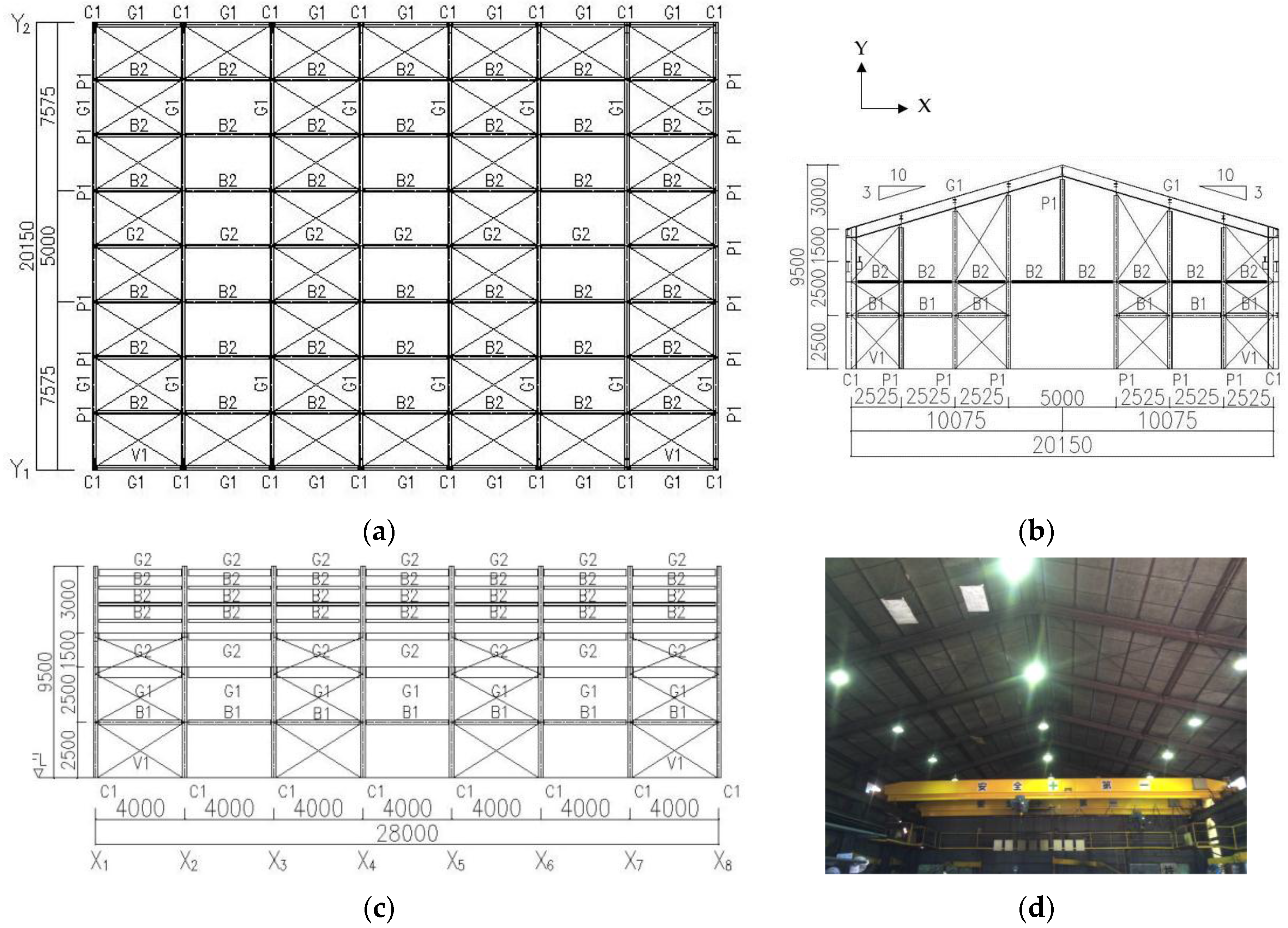
2.1. Target Building

The target building of the investigation is a factory using non-fireproofed rolled wide flanges, a type of steel that has been standardized mainly by steel manufacturers. The factory is a typical mountain shape and is located in an industrial district. The factory building was completed in the 1970s and is still in use; a demolition plan has not yet been determined. Although this factory building has seen a change of owner, there is no record of overload or fire damage according to the survey. Diagnosis charts, steel inspection certificates, and drawings and specifications are not available. The building’s roof plan, the framing elevation, the cross section, and the structural members’ list are shown in Figure 1 and Table 1 respectively. The building is a one-way rigid frame, a one-way brace structure (3-ton crane is installed) with a span of 20.15 m and an eaves height of 6.5 m. As for external cladding, folded plates are used for the roofing and siding of the walls.

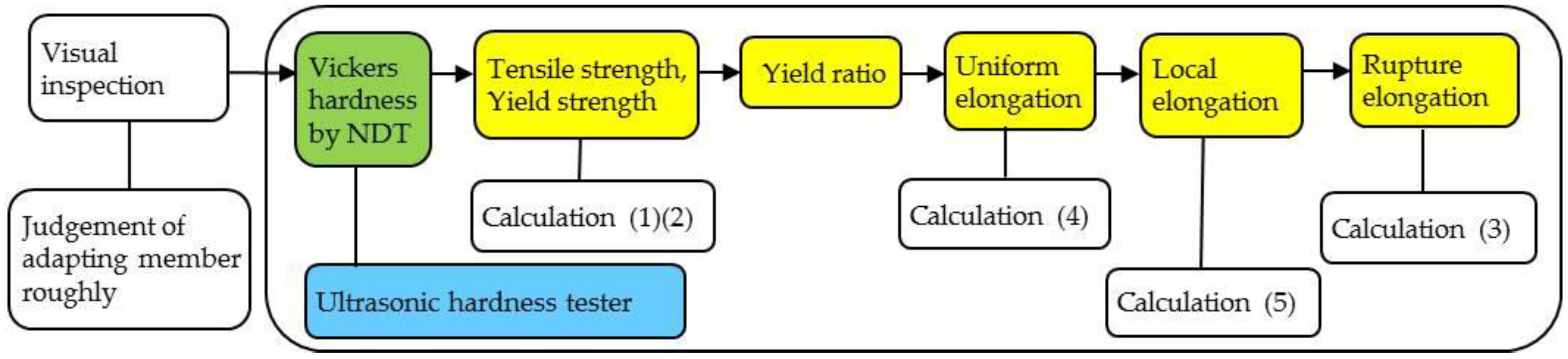
2.2. Flow for Estimating Mechanical Properties

The performance evaluation of steel structural members entails material testing, chemical composition testing, dimensional inspection, and degradation testing. In most cases, non-destructive testing is used for dimensional inspection, degradation testing, and destructive testing for material testing and chemical composition testing. Assuming that the structural members are to be reused, this paper focuses on non-destructive testing and examines the tensile strength, yield point or yield strength, and elongation, among other mechanical properties. Excessive deformation and damage in the steel structural members are evaluated via visual inspection. Figure 2 shows an estimation flow of the above-mentioned mechanical properties of the steel structural members assumed to be reused. First, the Vickers hardness of the steel structural members is measured using an ultrasonic hardness tester to calculate the tensile strength, and the yield point or yield strength, to eventually find the yield ratio. As mentioned above, an approach to estimating the tensile strength from the Vickers hardness employs the correlation between the surface hardness of a welded joint and the Vickers hardness [14,15]. Then, using the yield ratio thus obtained, the uniform elongation is calculated. Local elongation is calculated using the plate thickness of the structural members. Uniform elongation is considered to be independent of the shape of the test piece and to have a strong correlation with the yield ratio [16]. Elongation after fracture is calculated by summing the uniform elongation and local elongation.

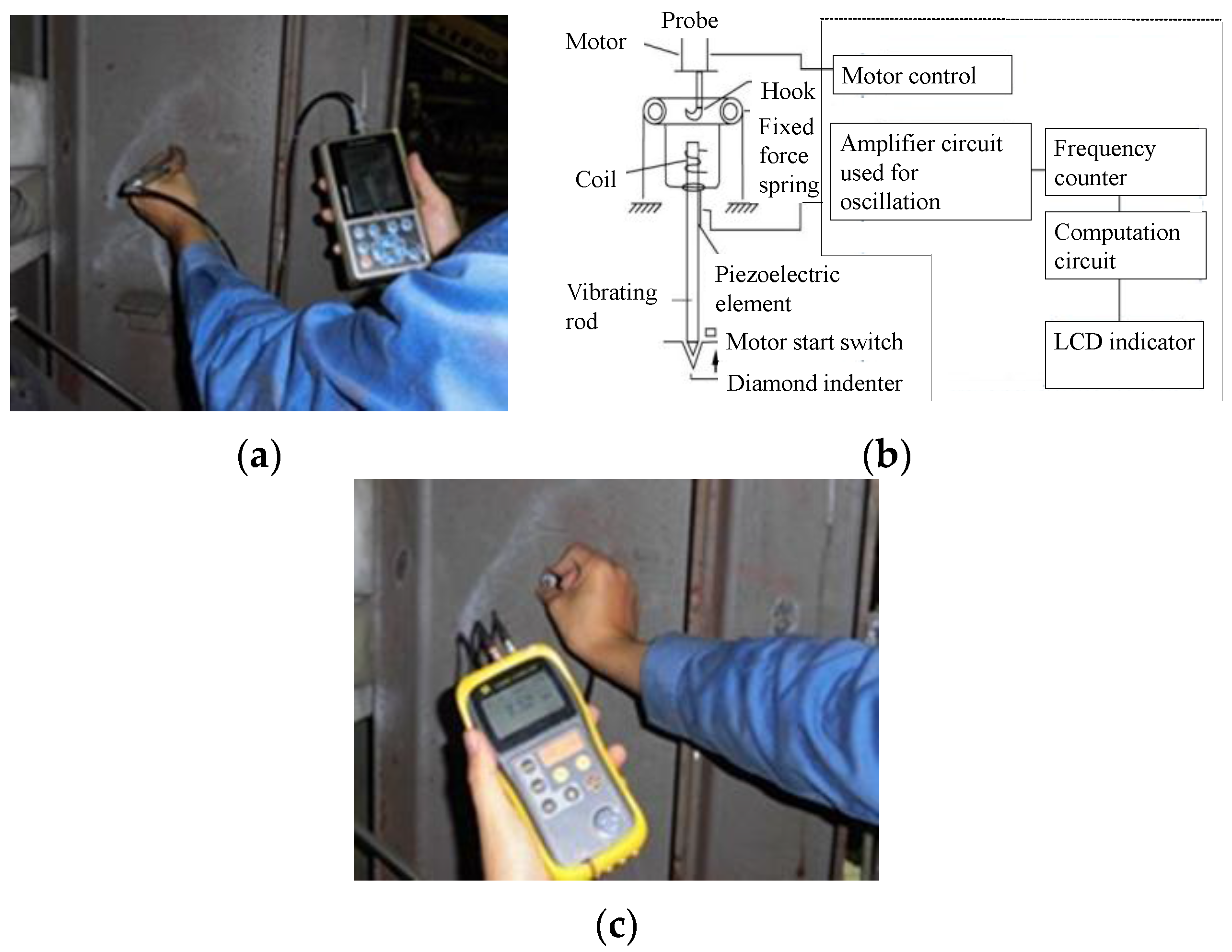
2.3. Non-Destructive Testing Equipment

Non-destructive tests consist mainly of portable ultrasonic hardness testers and rebound type portable hardness meters. Eventually, the portable ultrasonic hardness tester shown in Figure 3a,c is used for the maintenance of large-scale structures, steel towers, and bridges, and its Vickers hardness can be calculated using the frequency of the vibration rod at the pressing. Instead of measuring the size of the indentation of steel using a microscope, this tester employs a diamond indenter equipped with a vibrating rod that presses on the steel surface at a fixed load, and this tester measures its hardness by applying ultrasonic vibrations and analyzing its damping effect [17,18,19,20,21]. When the vibration rod is applied to a soft-surfaced steel with identical qualities and at a fixed force, it makes a deep indentation and becomes locked into the groove. Because of this, the resonance frequency increases. Conversely, it does not become locked in when it is used on hard steel and the resonance frequency drops. The Vickers hardness can be calculated using the correlation between this deviation and the tested hardness. The measuring indenter is the diamond indenter to the Micro-Vickers facing to the surface angle of 136 degrees. The measuring range for the Vickers hardness is from HV50 to HV999, and its reproducibility is within ±3% rdg HV. Using the ultrasonic thickness gauge shown in Figure 3c, the thickness of the rolled H section-steel was also measured.

3. Evaluation of Mechanical Properties

Table 2 lists the test pieces selected for investigating the mechanical properties of the steel structural members assumed to be reused. The tensile test is conducted in the mechanical properties test of JIS Z 2241, whose specifications correspond to ISO 6892-1 [22,23]. The steels contained in Series 1 are for adjusting the ultrasonic hardness tester used in non-destructive testing. Series 2 is the data of the steels for which the surface hardness is subscribed [24].

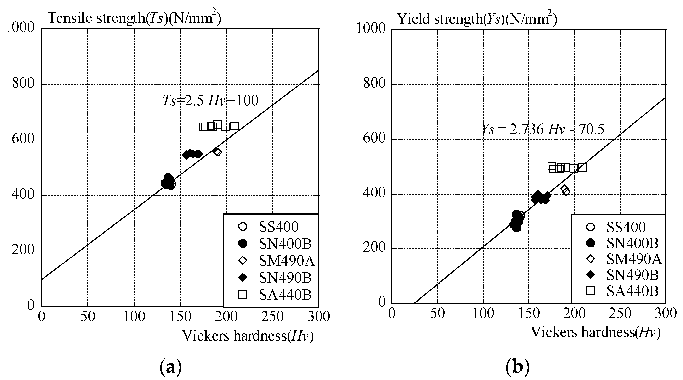
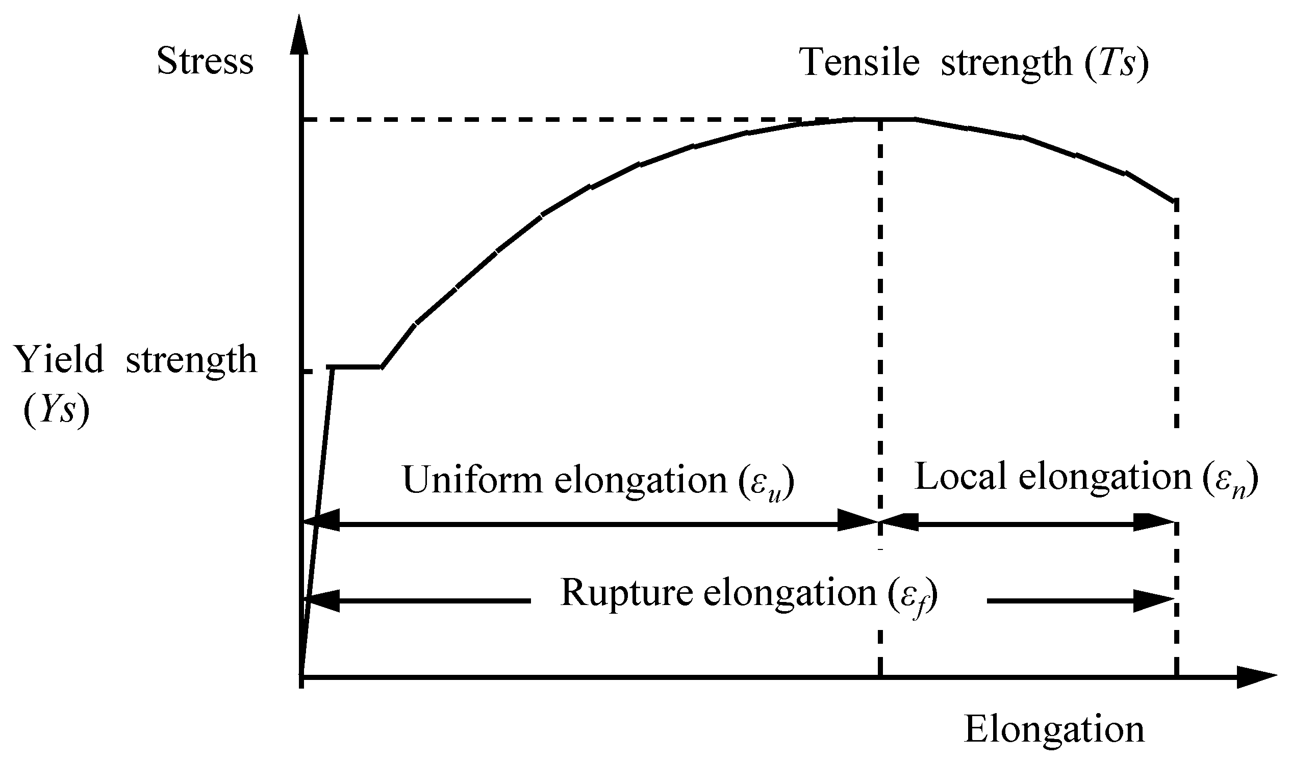
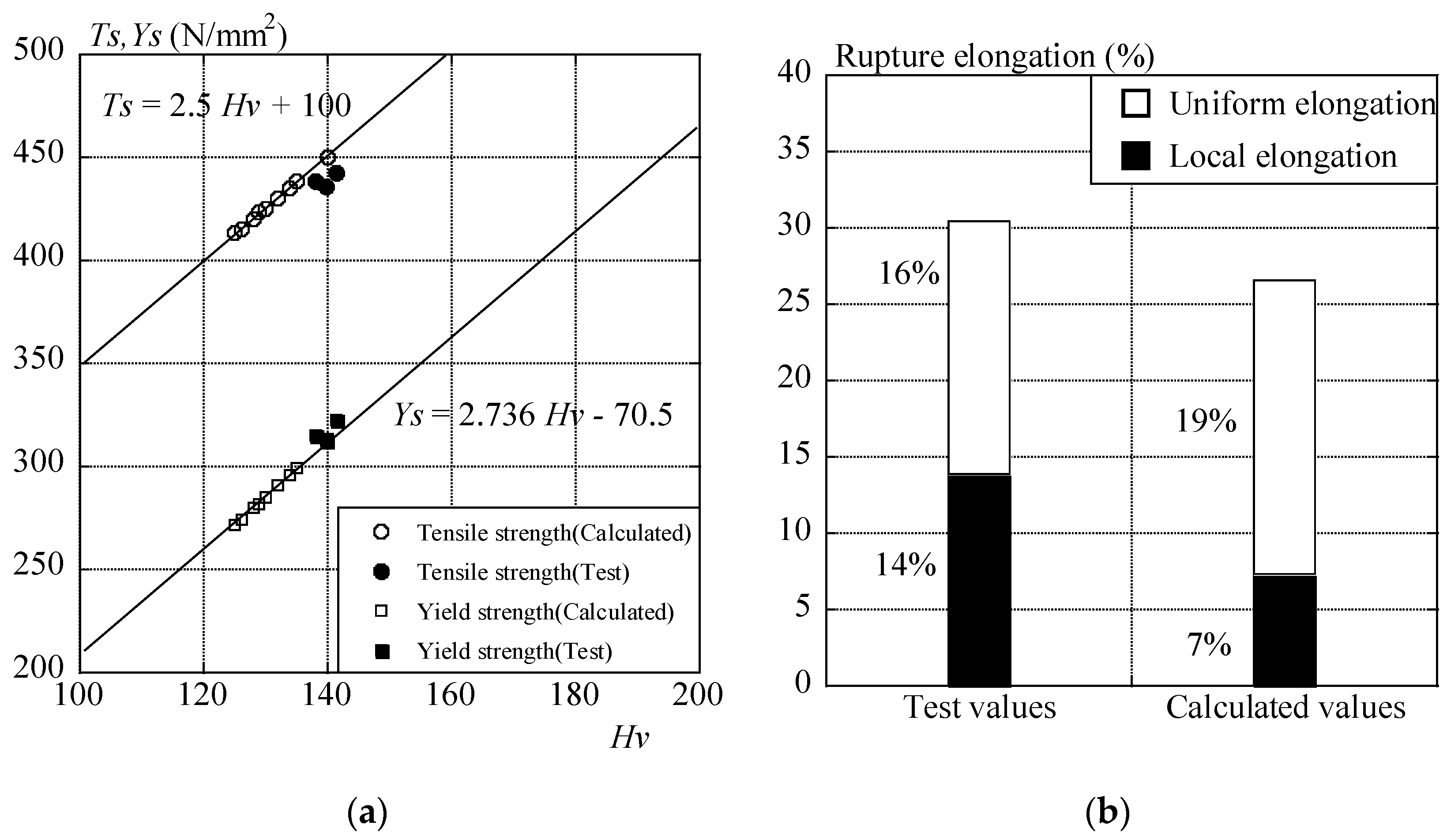
3.1. Tensile Strength and Yield Point or Yield Strength

Tensile strength and yield point or yield strength are estimated from the Vickers hardness using Equations (1) and (2), taking into consideration the Vickers hardness set for each yield ratio range [15,25,26,27]:
Ts = 2.5·Hv + 100
Ys = 2.736·Hv − 70.5
where Ts = tensile strength (N/mm2); Hv = Vickers hardness; Ys = yield point or yield strength (N/mm2).
Tensile strength and yield point or yield strength are estimated from Vickers based on the test piece list shown in Table 2. The correlation between Vickers hardness and tensile strength as well as that between Vickers hardness and yield point or yield strength is presented graphically in Figure 4. Although the data is not sufficient, the tensile strength and the yield point or yield strength nearly satisfy Equations (1) and (2).

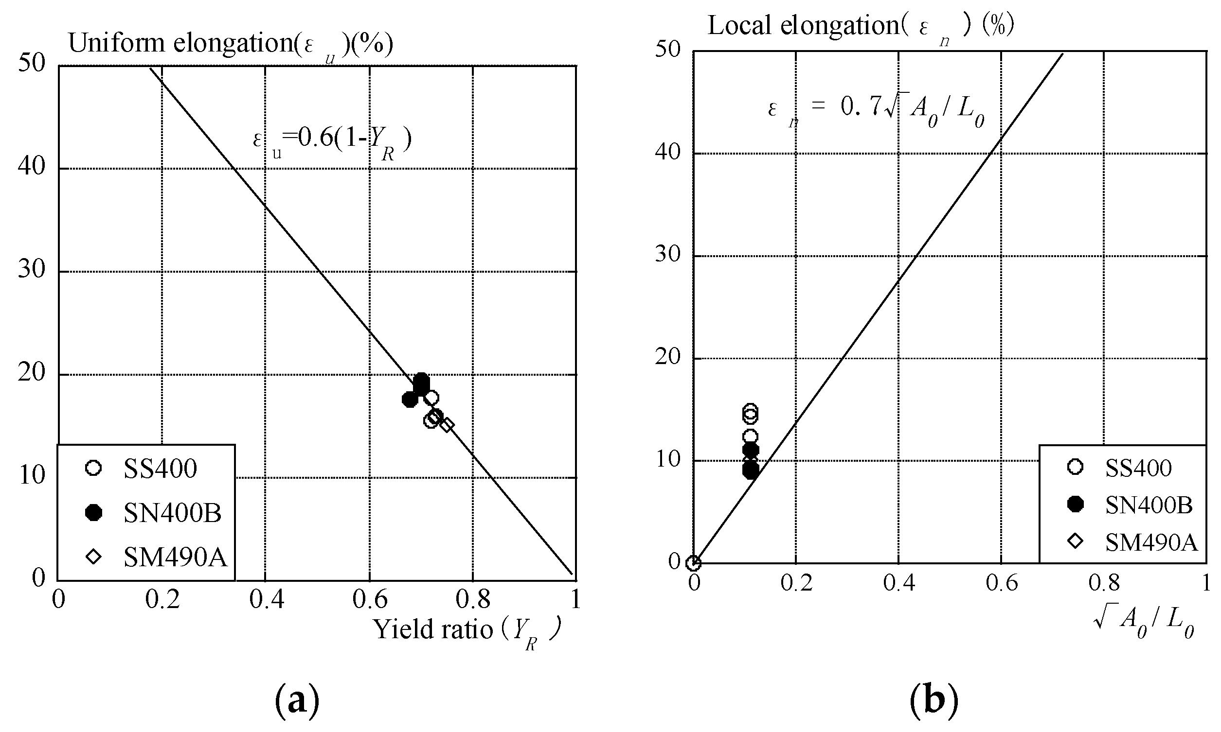
3.2. Rupture Elongation

In the stress–strain curve of a steel structural member, rupture elongation can be represented by uniform elongation and local elongation, as shown in the schematic diagram in Figure 5. The latter indicates elongation from the point where constriction starts to develop in the parallel part of the test piece to the point where the test piece fractures. It is the fusiform elongation that develops in part of the sections after being subjected to the maximum load. It is considered that the point where constriction starts to develop and the point where the maximum load is reached do not coincide; here, however, rupture elongation is represented by the sum of uniform elongation and local elongation, as shown in Equation (3):
εf = εu + εn,
where εf = rupture elongation; εu = uniform elongation; εn = local elongation.
Uniform elongation is directly related to plastic deformation capacity, and there is a correlation between uniform elongation and yield ratio; hence, the following equation is proposed [28].
ε u = k ( 1 Y s T s ) = k ( 1 Y R )
where YR = yield ratio; k = correction factor (The mean value of correction factor k is 0.6).
The correlation between the uniform elongation of the steel structural members and the yield ratio is presented graphically in Figure 6a.
The uniform elongation of the steel structural members decreases with increasing yield ratio according to Equation (4), and uniform elongations of them shown in Table 2 (SS400, SN400B, and SM490A) are approximately plotted indicated in Equation (4).
Local elongation is independent of the type of steel used for the test pieces. Local elongation is proportional to the square root of the cross-sectional area of the parallel part of a test piece, A0, and is inversely proportional to the gauge length of a test piece, L0, as shown in Equation (5). Moreover, a formula to calculate local elongation using uniform elongation and area reduction obtained from testing is proposed based on the fact that rupture elongation varies depending on the shape of the test piece, e.g., gauge length [25]. Currently, however, it is difficult to measure the area reduction by means of non-destructive testing, so Equation (5) is to be used only for rectangular test pieces:
ε n = γ A 0 L 0
where L0 = gauge length of a test piece; A0 = original cross-sectional area of the parallel part of a test piece; γ = coefficient indicating local elongation (γ = 0.7).
The correlation between the local elongation of the steel structural members and A 0 / L 0 is presented graphically in Figure 6b. Here, γ indicates the coefficient of local elongation by regression analysis. As seen in the figure, local elongation tends to increase in proportion to A 0 / L 0 . The local elongations of the steel structural members shown in Table 2 (SS400, SN400B, and SM490A) are slightly larger than the line of Equation (5).
Based on this fact, the cross-sectional area required for the calculation of local elongation is set by measuring the plate thickness of the target structural member.
From the above, rupture elongation is found by calculating the sum of the uniform elongation and local elongation using Equations (4) and (5), as shown in Equation (3).

3.3. Degradation

Degradation evaluation of the steel structural members is performed based on dimensional inspection and coating degradation evaluation (JIS K 5600-8-1 to 6), whose certification corresponds to ISO 4628-1-6, ASTM D714-02, and ASTM D610-01 [29,30,31,32,33]. In the dimensional inspection, the plate thickness of the structural members is measured with Vernier calipers or a micrometer. Where the dimensional inspection results indicate that such structural members do not meet the requirements for reuse specified in the current JIS standard (JIS G 3192: Shape, dimensions, mass and allowable error of hot-rolled steel), they are corrected so that they fall within the range of allowable error [33,34]. The degradation of paint coatings is evaluated according to the degree of blistering, rusting, cracking, flaking, and chalking based on JIS K 5600-8-1 (Testing methods for paints—Evaluation of degradation of paint coatings). For example, the degree of rusting is expressed by the magnitude and area of defect scattering (JIS K 5600-8-3: Degree of rusting).

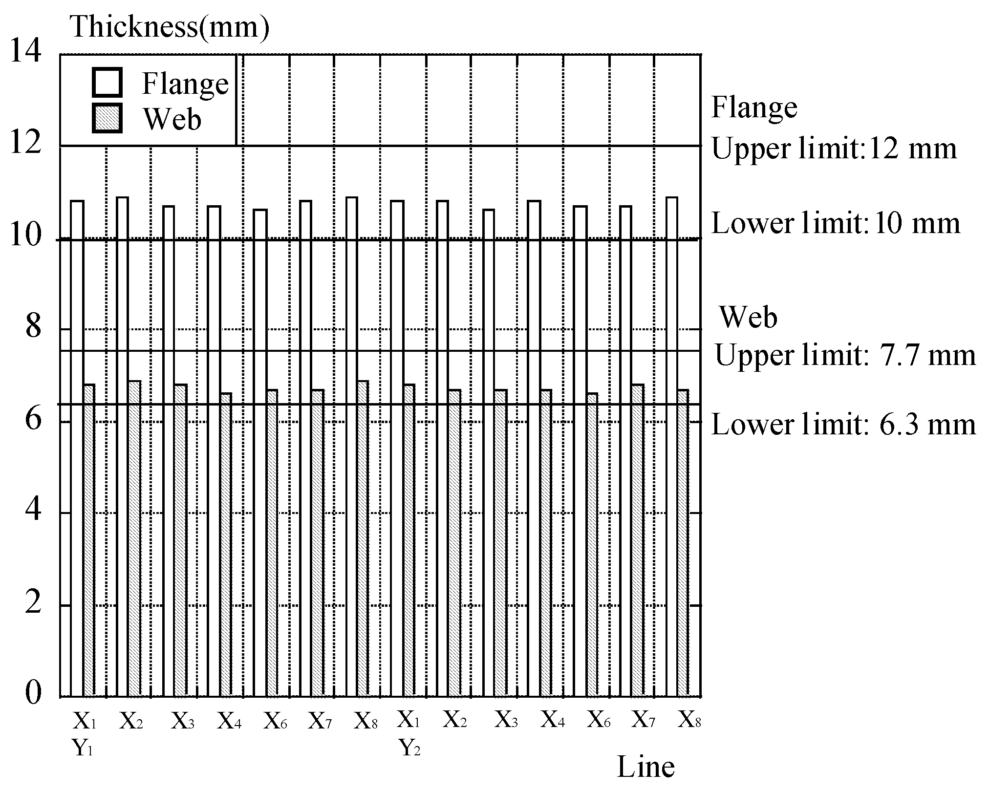
4. Example of Material Estimation

Based on the estimation flow of material properties mentioned in the preceding chapter, this chapter examines the mechanical properties and the degradation status of the structural members of the steel structure targeted for investigation by means of non-destructive testing. Among the mechanical properties, this paper focuses on tensile strength, yield point or yield strength, and elongation.

4.1. Mechanical Properties
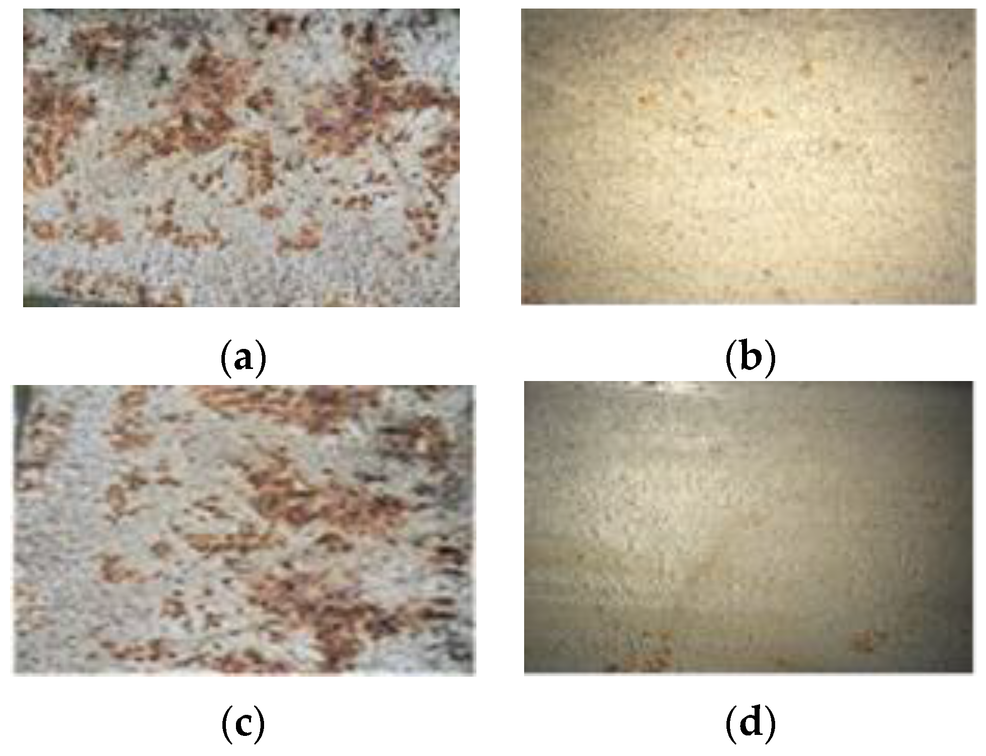
Vickers hardness of the columns along individual lines by nondestructive testing is measured, and the tensile strength, yield point or yield strength, and uniform elongation are calculated using the above-mentioned Equations (1)–(5). Vickers hardness, tensile strength, yield point or yield strength are shown in Figure 7a. The test values and calculated values of rupture elongation are plotted in Figure 7b. The test values obtained by destructive test pieces (Series_1) are tensile strength, yield strength, and elongation, and they have average of three specimens. The Vickers hardness is also measured with the same test pieces via nondestructive testing.
The measured object was the flange (a plate thickness of 11 mm) of a column (H-350 × 175 × 7 × 11), and its Vickers hardness (Hv) was found to be 125–140. Prior to measurement, surface grinding was performed on the flange. The Vickers hardness (Hv) of the columns (a height of Floor level +1.0 m) at 14 locations along the individual lines shown in Figure 1 was measured three times each, and the mean value of the measurements was taken. As a result of calculations, tensile strength is 413–450 N/mm2, yield point or yield strength is 272–313 N/mm2, and the rupture elongation is 19%–21%. The plate thickness of the structural members being 11 mm, rupture elongation of test values is 30%, which is 1.15 times larger than the calculated values.
The mechanical properties of 400 and 500 N/mm2 class steels (JIS standard) are tabulated in Table 3. As the corresponding value of the tensile strength obtained from the Vickers hardness measurements falls within the range of 400 to 510 N/mm2 specified in JIS, all 400 N/mm2 class steels fulfill the tensile strength requirements specified in JIS. As for the corresponding value of the yield point or yield strength, the lower limit specified in JIS being 225 N/mm2, all 400 N/mm2 class fulfill the JIS requirements, as in the case of tensile strength. However, 500 N/mm2 class steels do not fulfill the JIS requirements as they fail to meet the lower limits of tensile strength and yield point or yield strength. The calculated average value of elongation is 20%. SS400 and SN400A steels with the lowest limit of elongation fulfill the JIS requirements, and its deference of elongation of JIS is small. The target building was constructed in the 1970s, during which time SN steel was not manufactured, so SN steel is excluded from consideration. From this, the material properties of the steel structural members correspond to SS400, SM400A, SM400B, and SM400C. Designing these members for reuse is desirable for SS400 safety.

4.2. Degradation

Degradation evaluation of the steel structural members was performed based on dimensional inspection and coating degradation evaluation, as mentioned in Section 3.2. In the visual inspection, excessive deformation due to overload and fire damage was not found in the structural members; however, a considerable amount of rust was observed. Typical coating degradation of the column flanges is shown in Figure 8 and Table 4 [29]. The volume of rust on the structural members in the vicinity of the openings is slightly larger than that on the structural members located away from the openings. The rust status of the structural members located in the vicinity of the openings along the Y1 and Y2 lines corresponds to Ri5(S5). The rust status of the structural members at the other locations is mostly Ri4(S4). The coating film thickness of the structural members along the Y1 line and the Y2 line is 65–102 μm and 65–99 μm, respectively. The coating film thickness of the columns located away from the openings is slightly larger than that of the columns in the vicinity of the openings. The distribution of the plate thickness of the flanges and webs of the columns along individual lines is shown in Figure 9. Although both the flanges and webs have a deference of varying degrees of coating degradation, with the tolerance of the plate thickness of the former being ±1.0 mm and that of the latter being ±0.7 mm, they satisfy the JIS requirements [33,34,35,36]. From Section 4.1 and Section 4.2, it is considered that the material of the steel structural members of the target building correspond to SS400 and that these members can be reused.

5. Conclusions

By means of non-destructive testing, this study examined the mechanical properties, namely, tensile strength, yield point or yield strength, yield ratio, and elongation, and the degradation status of steel structural members assumed to be reused. The test results revealed the following:
(1)
Based on Vickers hardness found via NDT, this paper proposed a flow for estimating the mechanical properties of the steel structural members. Tensile strength and yield point or yield strength were calculated using Vickers hardness. Uniform elongation and local elongation of the steel structural members were calculated using the yield ratio and plate thickness of the structural members, respectively.
(2)
The proposed estimation flow of mechanical properties, e.g., tensile strength, yield point or yield strength, and rupture elongation, was verified applying to a target building steel structure.
Since the data of the correlation between Vickers hardness via NDT and mechanical properties is small, statistical analysis has not been conducted yet. By storing a database of mechanical properties, such as tensile strength, yield point or yield strength, and elongation, measured by test pieces, statistical analysis can be conducted in the near future.

Acknowledgments

The authors wish to thank Mamoru Iwata, at Kanagawa University, for his cooperation in performing this study.

Author Contributions

The first author (Masanori Fujita) planned out the concept and carried out the survey test. The second author (Keiichi Kuki) carried out the survey test and supported the first author, and the corresponding authors controlled the entire project.

Conflicts of Interest

The authors declare no conflict of interest.

References

  1. Japan Meteorological Agency. IPCC Fourth Assessment Report; Ministry of the Environment: Tokyo, Japan, 2007.
  2. Architectural Institute of Japan. Activity report “architectural approach to global warming (Dec.1997 presidential statement)”. Archit. J. 1998, 113, 90–91. Available online: http://www.aij.or.jp/jpn/archives/971202.htm (accessed on 20 October 2014). [Google Scholar]
  3. Architectural Institute of Japan. Towards the Architecture for a Global Environment; Shokokusha Publishing Co., Ltd.: Tokyo, Japan, 2002. [Google Scholar]
  4. Manual for Re-Using Structural Members; Architectural Institute of Japan: Tokyo, Japan, 2009.
  5. Architectural Institute of Japan. Proposal 2050 Vision, Building-related Measures to Counteract Global Warming Towards Carbon-Neutralization. December 2009. Available online: http://www.aij.or.jp/scripts/request/document/20091222-1e.pdf (accessed on 20 October 2014).
  6. Fujita, M.; Iwata, M. Reuse system for building steel structures. Struct. Infrastruct. Eng. 2008, 4, 207–220. [Google Scholar] [CrossRef]
  7. Fujita, M.; Iwata, M. The Reuse Management Model of Building Steel Structures. In Proceedings of the International ECCE Conference Euroinfra 2009, Current State and Challenges for Sustainable Development of Infrastructure, Helsinki, Finland, 15–16 October 2009; pp. 15–16.
  8. Fujita, M.; Iwata, M. Reuse dismantling and structural performance of reusable members. Struct. Eng. Int. 2008, 18, 230–237. [Google Scholar] [CrossRef]
  9. Fujita, M.; Iwata, M. Guideline for reusable members of building steel structures and test. In Codes in Structural Engineering Developments and Needs for International Practice; IBASE: Sharm el-Sheikh, Egypt, 2010; pp. 545–552. [Google Scholar]
  10. Fujita, M. Reuse system of building steel structures—Structural performance of reusable members and practical examples—Novel and non-conventional materials and technologies for sustainability. Key Eng. Mater. 2012, 517, 513–521. [Google Scholar] [CrossRef]
  11. Iwata, M.; Fujita, M. A damage-controlled structure using buckling-restrained knee braces. Struct. Eng. Int. 2011, 21, 462–470. [Google Scholar] [CrossRef]
  12. Fujita, M.; Masuda, T. Application of Various NDT Methods for the Evaluation of Building Steel Structures for Reuse. Materials 2014, 7, 7130–7144. [Google Scholar] [CrossRef]
  13. Aoyagi, R.; Umezu, K. Comparison of ultrasonic-hardness-tester hardness and micro-vickers hardness. Jpn. J. Appl. Phys. 2007, 46, 4558–4560. [Google Scholar] [CrossRef]
  14. Cahoon, J.R.; Broughton, W.H.; Kutzak, A.R. The determination of yield strength from hardness measurements. Metall. Trans. 1971, 2, 1971–1979. [Google Scholar]
  15. The Japan Welding Engineering Society. Quality Performance Method of Welding Connections of Building Steel Structures; Technical Report for The Japan Welding Engineering Society: Tokyo, Japan, 2006. [Google Scholar]
  16. Suzuki, H.; Horikawa, K. On the uniform elongation of structural steels. J. Struct. Eng. 1992, 38A, 979–987. Available online: http://library.jsce.or.jp/jsce/open/00127/1992/38-3-0979.pdf (accessed on 18 October 2016). [Google Scholar]
  17. Kleesattel, C.; Gladwell, G.M.L. The contact-impedance meter-1. Ultrasonics 1968, 6, 175–180. [Google Scholar] [CrossRef]
  18. Kleesattel, C.; Gladwell, G.M.L. The contact-impedance meter-3. Ultrasonics 1969, 7, 57–62. [Google Scholar] [CrossRef]
  19. Bradfield, G. Strength, elasticity and ultrasonics. Ultrasonics 1972, 10, 166–172. [Google Scholar] [CrossRef]
  20. Szilard, J. Quicker, simpler hardness testing using ultrasonics. Ultrasonics 1984, 22, 174–178. [Google Scholar] [CrossRef]
  21. Bouda, A.B.; Benchaala, A.; Alem, K. Ultrasonic characterization of materials hardness. Ultrasonics 2000, 38, 224–227. [Google Scholar] [CrossRef]
  22. JIS Z 2241. Metallic Materials Tensile Testing Method of Test at Room Temperature; Japanese Industrial Standards Committee: Tokyo, Japan, 2011. [Google Scholar]
  23. ISO 6892-1. Metallic Materials—Tensile Testing—Part 1: Method of Test at Room Temperature; Japanese Industrial Standards Committee: Tokyo, Japan, 2009. [Google Scholar]
  24. Kaneya, T. Experiment research of tensile strength, yield point, and Vickers hardness concerning correlation. Synop. Archit. Inst. Jpn. 2006, 6, 989–990. [Google Scholar]
  25. Iwata, Y.; Ishihara, T.; Mukai, A.; Nishiyama, I.; Aoki, H. Relation between uniform elongation and rupture elongation at coupon tension tests of structural steel. AIJ J. Struct. Constr. Eng. 2013, 78, 223–232. [Google Scholar] [CrossRef]
  26. The Japan Welding Engineering Society. Weldable High Strength Steel Plates; The Japan Welding Engineering Society: Tokyo, Japan, 2012. [Google Scholar]
  27. Pavlina, E.J.; van Tyne, C.J. Correlation of Yield Strength and Tensile Strength with Hardness for Steels. J. Mater. Eng. Perform. 2008, 17, 888–893. [Google Scholar] [CrossRef]
  28. Suzuki, H. A theoretical equation of relationship between uniform elongation and yield ratio of structural steels. J. Constr. Steel 1994, 2, 473–478. [Google Scholar]
  29. JIS K 5600-8. Testing Methods for Paints—Part 8: Evaluation of Degradation of Coatings; Japanese Industrial Standards Committee: Tokyo, Japan, 2014. [Google Scholar]
  30. ISO 4628. Paints and Varnishes—Evaluation of Degradation of Coatings—Designation of Quantity and Size of Defects, and of Intensity of Uniform Changes in Appearance; International Organization for Standardization: Geneva, Switzerland, 2003. [Google Scholar]
  31. ASTM D 714-02. Standard Test Method for Evaluating Degree of Blistering of Paints; American Society for Testing and Materials: West Conshohocken, PA, USA, 2009. [Google Scholar]
  32. ASTM D 610-01. Standard Method of Evaluating Degree of Rusting on Painted Steel Surfaces; American Society for Testing and Materials: West Conshohocken, PA, USA, 2006. [Google Scholar]
  33. JIS G 3192. Dimensions, Mass and Permissible Variations of Hot Rolled Steel Sections; Japanese Industrial Standards Committee: Tokyo, Japan, 2014. [Google Scholar]
  34. JIS G 3101. Rolled Steels for General Structure; Japanese Industrial Standards Committee: Tokyo, Japan, 2010. [Google Scholar]
  35. ISO 630. Structural Steels—Plates, Wide Flats, Bars, Sections and Profiles; International Organization for Standardization: Geneva, Switzerland, 1995. [Google Scholar]
  36. JIS G 0321. Product Analysis and Its Tolerance for Wrought Steel; Japanese Industrial Standards Committee: Tokyo, Japan, 2010. [Google Scholar]
Figure 1. (a) Plan; (b) elevation (x-axis); (c) elevation (y-axis); (d) interior view. Unit: mm.
Metals 06 00247 g001
Figure 2. Estimation flow of mechanical properties.
Metals 06 00247 g002
Figure 3. (a) A portable hardness tester and (b) the measurement principle of the portable hardness tester. (c) Portable thickness gauge.
Metals 06 00247 g003
Figure 4. (a) Tensile strength and Vickers hardness and (b) yield point or yield strength and Vickers hardness.
Metals 06 00247 g004
Figure 5. Schematic diagram of stress-strain correlation.
Metals 06 00247 g005
Figure 6. (a) Uniform elongation and yield ratio and (b) local elongation and A 0 / L 0 .
Metals 06 00247 g006
Figure 7. (a) Tensile strength, yield point or yield strength, and Vickers hardness and (b) test values and calculated values of uniform elongation and local elongation.
Metals 06 00247 g007
Figure 8. Coating degradation of column (a) Ri5(S5), Y1X1 line; (b) Ri4(S4), Y1X6 line; (c) Ri5(S5), Y2X1 line; (d) Ri4(S4), Y2X8 line.
Metals 06 00247 g008
Figure 9. Thickness of the flange and web of the column.
Metals 06 00247 g009
Table 1. The members’ list of the building steel structure.
LocationMarkSize
BeamG1H-400 × 200 × 8 × 13
G2H-350 × 150 × 6.5 × 9
ColumnC1H-350 × 150 × 7 × 11
Sub-beamB1H-200 × 100 × 5.5 × 8
B2H-150 × 75 × 5 × 7
Mid-columnP1H-250 × 250 × 9 × 14
BraceV11-M20
Purlin--C-100 × 50 × 3.2
Table 2. List of the test pieces.
SeriesMaterialType *Thickness mmYield Strength N/mm2Tensile Strength N/mm2Uniform Elongation εu (%)Rupture Elongation εf (%)Vickers Hardness HvStrain Hardening CoefficientNumber Specimen
Series_1SS4001A1231343616311400.2498
1231543818301380.229
1232344216301410.236
SN400B1A1231045918291380.246
1232145918291370.248
1232746319281370.232
SM490A1A1241955915261890.205
1240855716261910.188
Series_2SN400B512279451--43137--21
12277449--44136--
12288442--37134--
12300443--44135--
12289445--41133--
12301448--42138--
12294445--43135--
SN490B512377550--36168--
12378545--38157--
12388547--39157--
12399552--36160--
12388550--38163--
12378549--36163--
12394550--38170--
SA440B1A40498657--26190--
40502647--25175--
40495647--25199--
40491647--26177--
40493651--25183--
40496648--24185--
40496649--24208--
* Type indicated specimens of JIS.
Table 3. Mechanical properties (JIS standard).
Materials GradeYield Strength (N/mm2)Tensile Strength (N/mm2)Rupture Elongation (%)
Lower Limit/Upper LimitLower Limit/Upper LimitLower Limit
6 ≤ t * < 1212 ≤ t < 16t = 1616 < t ≤ 406 ≤ t ≤ 1616 < t ≤ 50
SS400245/--245/--245/--235/--400/5101721
SM400A245/--245/--245/--235/--400/5101822
SM400B245/--245/--245/--235/--400/5101822
SM400C245/--245/--245/--235/--400/5101822
SN400A235/--235/--235/--235/--400/5101721
SN400B235/--235/355235/355235/355400/5101822
SN400C----235/355235/355400/5101822
SM490A325/--325/--325/--315/--490/6101721
SM490B325/--325/--325/--315/--490/6101721
SN490B325/--325/445325/445325/445490/6101721
SN490C----325/445325/445490/6101721
* Thickness of steel plates.
Table 4. Coating degradation evaluation.
LineThickness of Painting (μm)Mark of RustLineThickness of Painting (μm)Mark of Rust
Y1X174Ri5(S5)Y2X165Ri5(S5)
Y1X265Ri5(S5)Y2X274Ri5(S5)
Y1X367Ri4(S4)Y2X380Ri4(S4)
Y1X489Ri4(S4)Y2X472Ri4(S4)
Y1X685Ri4(S4)Y2X695Ri4(S4)
Y1X7102Ri4(S4)Y2X799Ri4(S4)
Y1X894Ri4(S4)Y2X886Ri4(S4)

