
The Study of Heat Treatment Effects on Chromium Carbide Precipitation of 35Cr-45Ni-Nb Alloy for Repairing Furnace Tubes

Abstract
:
1. Introduction
1.1. Material for Ethane Pyrolysis Furnaces Tube
1.2. Weldability with Thermal Heat Treatment
2. Materials and Methods
2.1. Material Verification

| Specimen | Information and Visual Inspection | Image | |
|---|---|---|---|
| Tube No. 1 (New) | Diameter (OD) | 63.4 ± 0.2 mm | 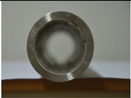 |
| Outside wall | Light gray shade | ||
| Inside wall | Original smooth surface | ||
| Visual inspection | No coke deposit, original roundness, no swell | ||
| Tube No. 2 (Used) | Location | 9 m on the ground | 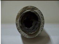 |
| Diameter (OD) | 67.8 ± 0.8 mm | ||
| Outside wall | Black shade & rough surface | ||
| Inside wall | Thin coke deposit | ||
| Visual inspection | Blockage of coke inside tube, poor roundness | ||
| Tube No. 3 (Used) | Location | 2 m on the ground |  |
| Diameter (OD) | 65.0 ± 0.4 mm | ||
| Outside wall | Black shade & rough surface | ||
| Inside wall | Thin coke deposit | ||
| Visual inspection | A little soot inside tube, Poor roundness | ||
| Tube No. 4 (Used) | Location | 1 m on the ground |  |
| Diameter (OD) | 65.0 ± 0.4 mm | ||
| Outside wall | Black shade & rough surface | ||
| Inside wall | Thin coke deposit inside tube | ||
| Visual inspection | Near original roundness | ||
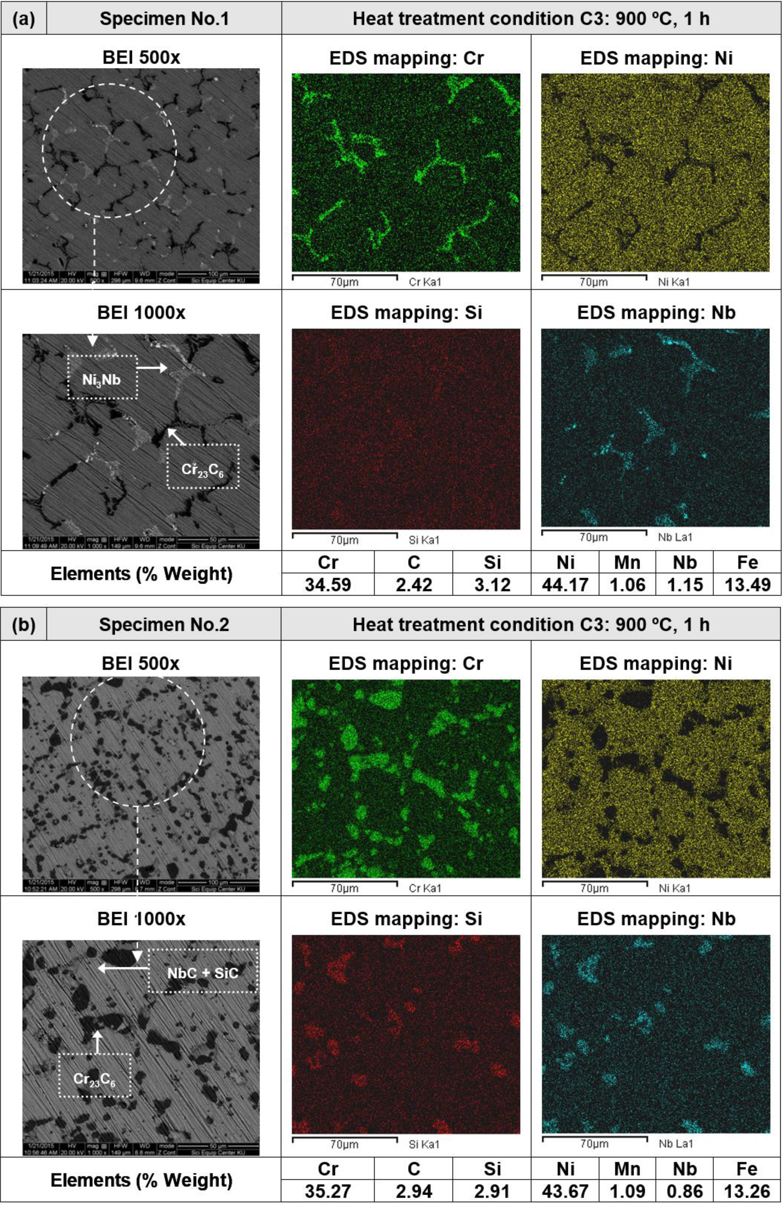
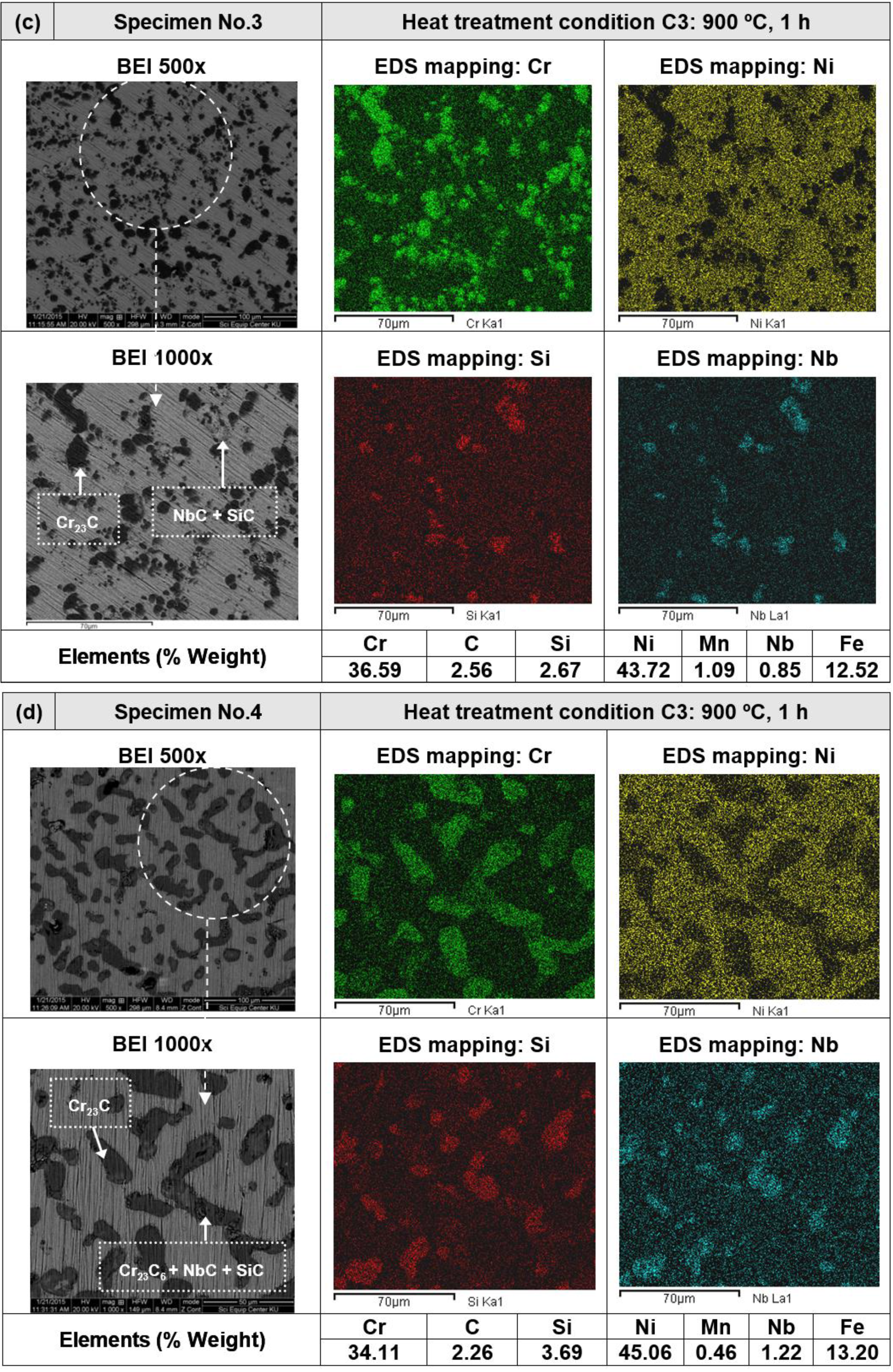
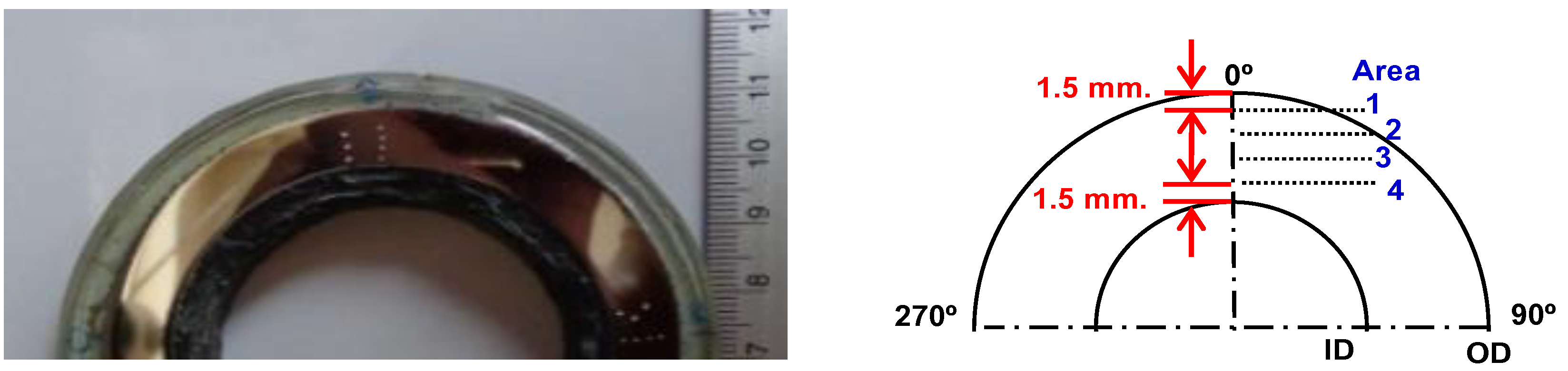
2.2. Heat Treatment, Hardness and Microstructure
| Conditions | Heat Treatment Methods | Note | |
|---|---|---|---|
| C1 | Without heat treatment | New tube (No. 1) | |
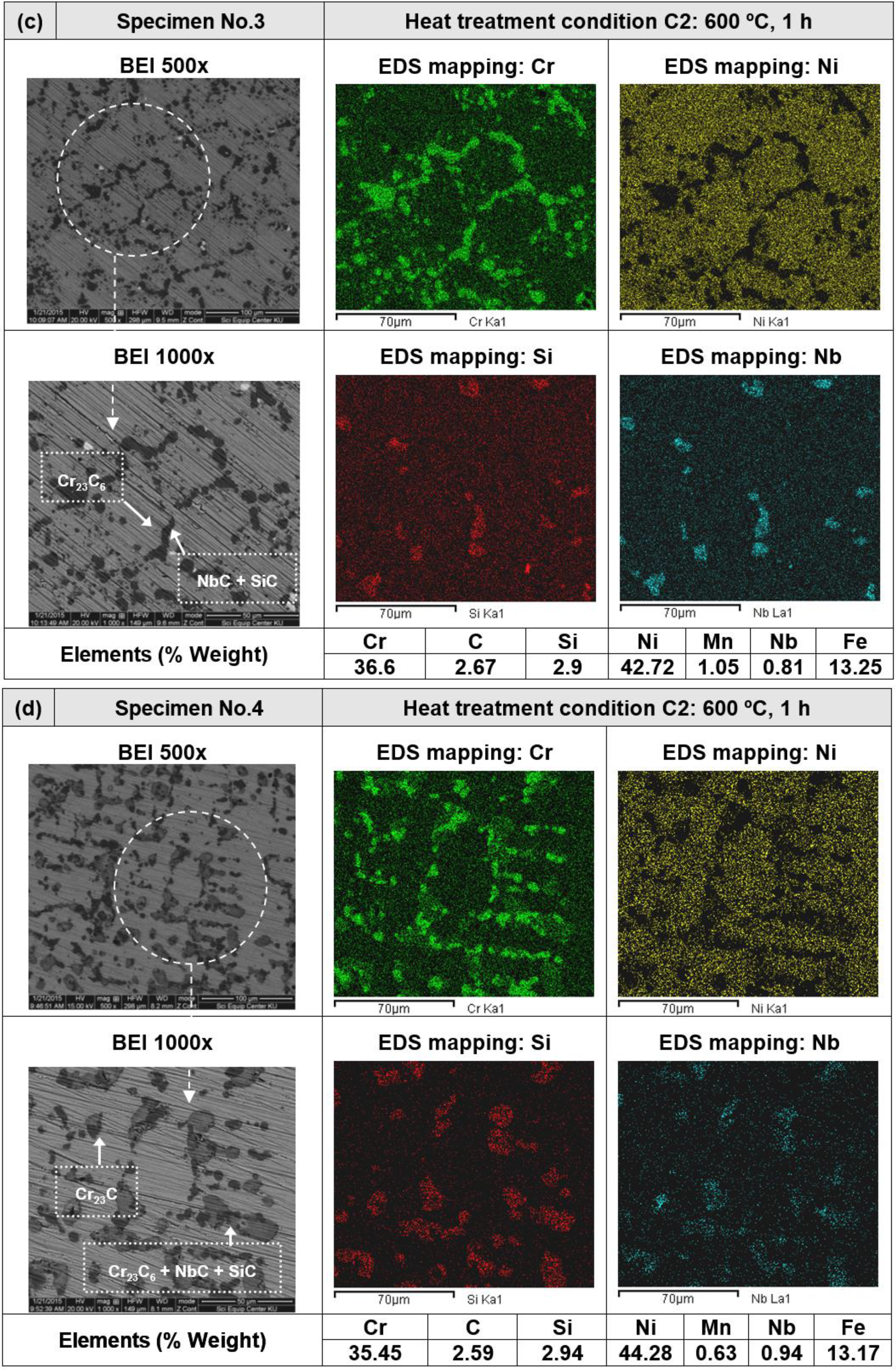
| C2 | Pre-heat 600 °C, 1 h | Cooled down in air | Used tube (No. 2–4) |
| C3 | Pre-heat 900 °C, 1 h | Cooled down in air | Used tube (No. 2–4) |
3. Results and Discussion
3.1. Material Verification
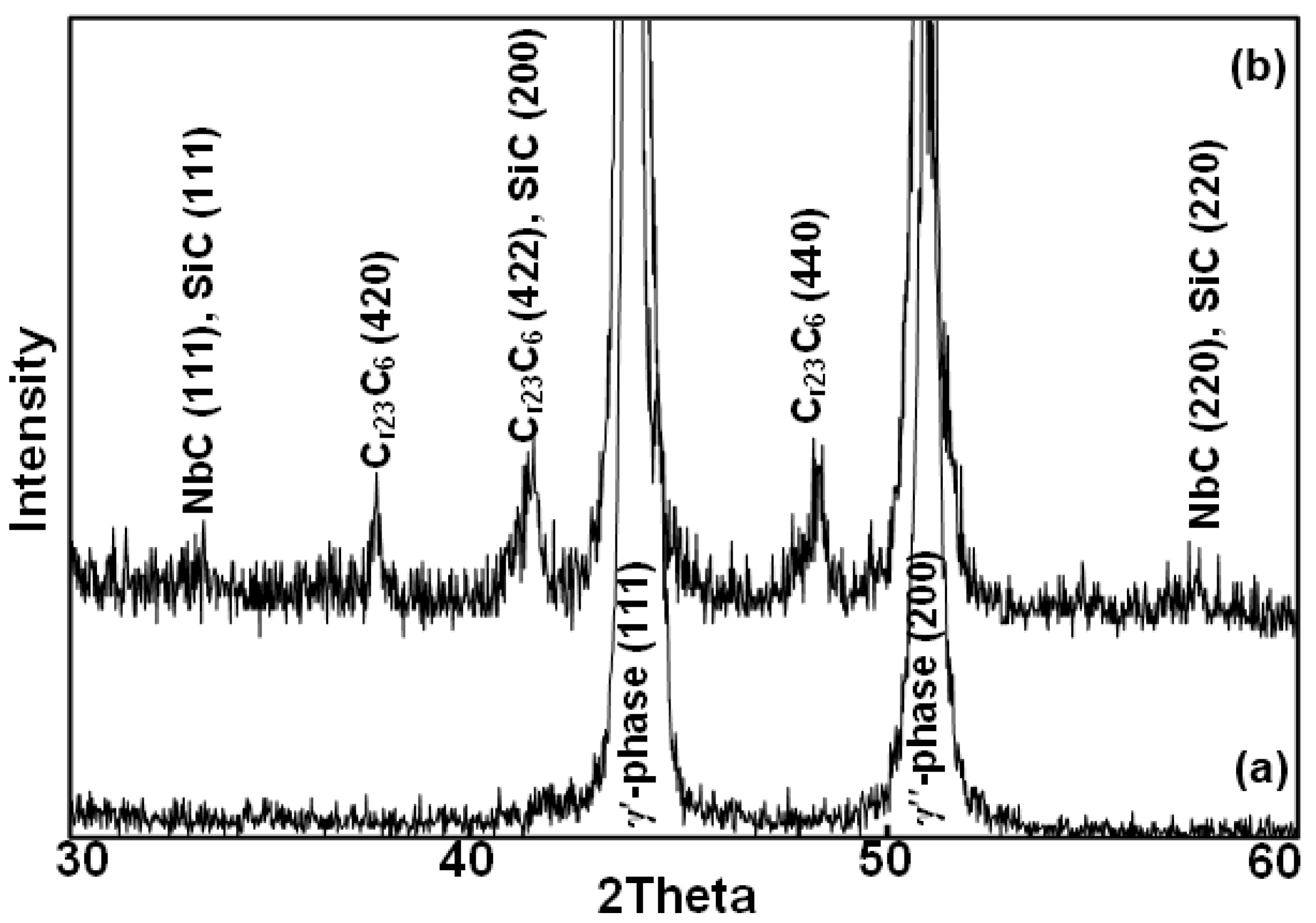

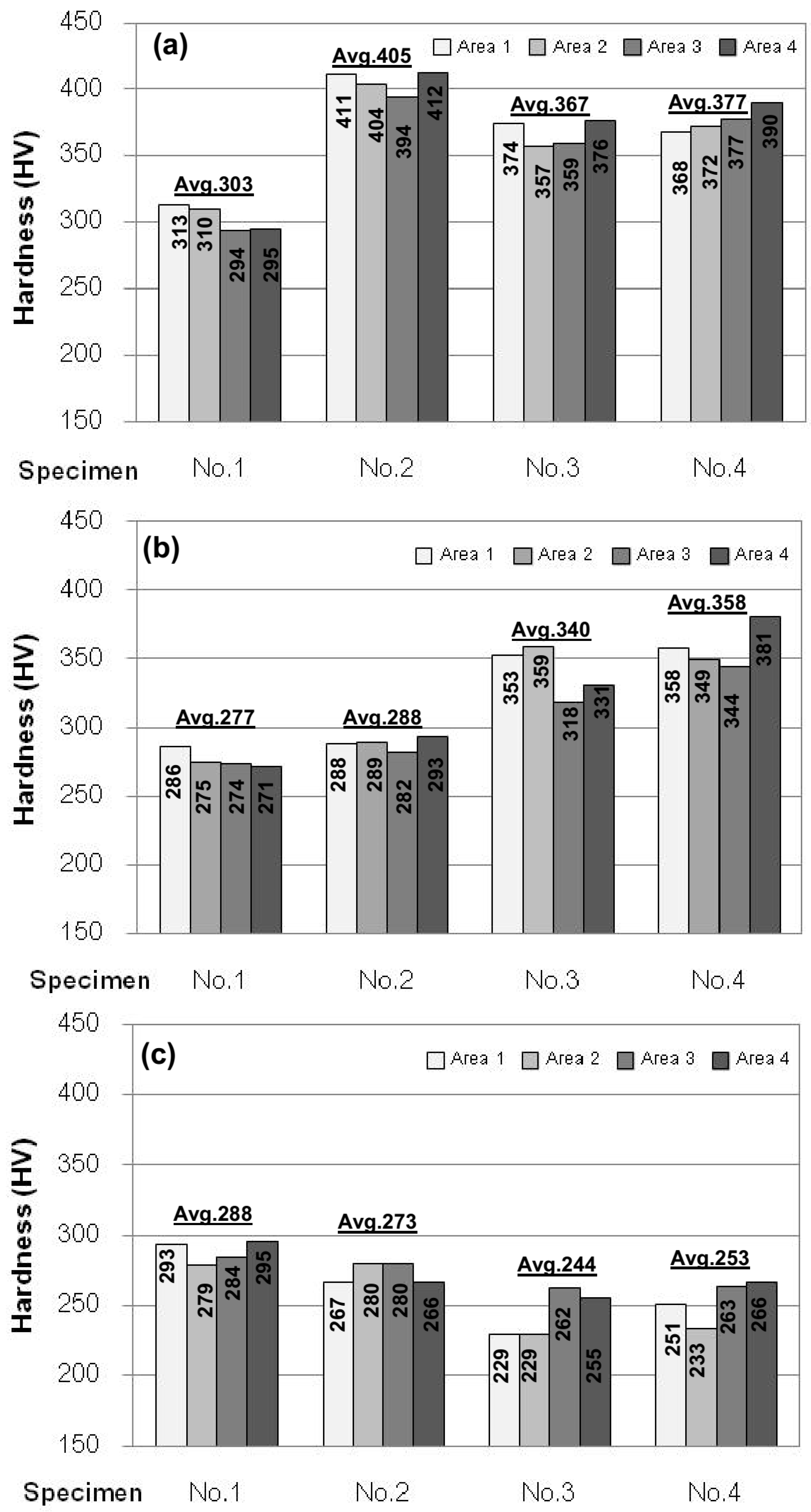
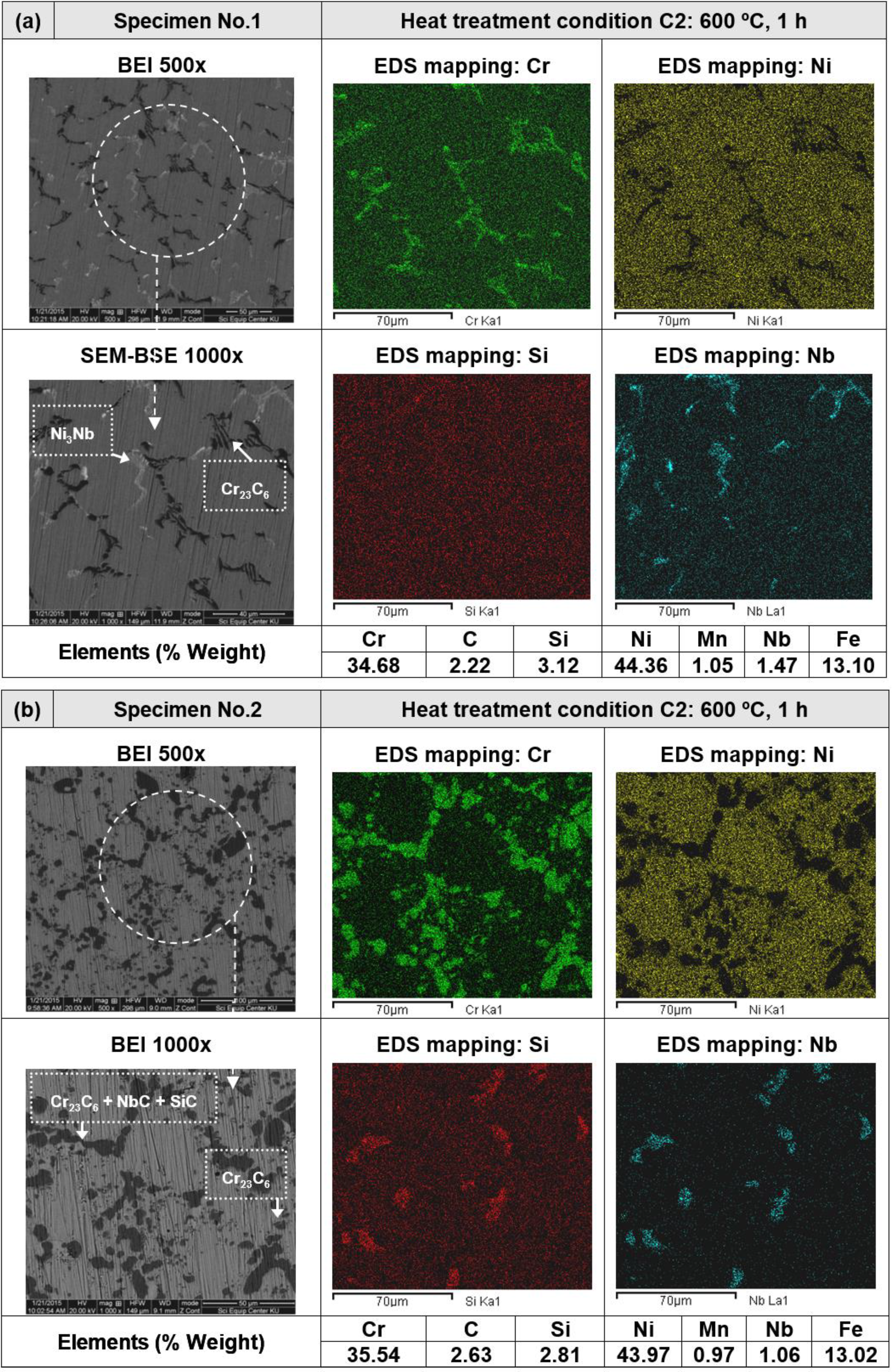
3.2. Heat Treatment, Hardness and Microstructure


4. Conclusions
Acknowledgments
Author Contributions
Conflicts of Interest
References
- Ul-Hamid, A.; Tawancy, H.M.; Al-Jaroudi, S.S.; Mohammed, A.I.; Abbas, N.M. Carburisation of Fe-Ni-Cr alloys at High Temperatures. Mater. Sci. Pol. 2006, 24, 219–331. [Google Scholar]
- Grabke, H.J. Carburization, Carbide Formation, Metal Dusting, Coking. J. Mater. Technol. 2002, 36, 297–305. [Google Scholar]
- Babakr, A.; Habiby, F. Lengthening, Cracking and Weld ability Problems of Fe-Ni-Cr Alloy Tube. J. Miner. Mater. Charact. Eng. 2009, 8, 133–148. [Google Scholar]
- Verdier, G.; Carpentier, F. Consider New Materials for Ethylene Furnace Applications. Hydrocarb. Process. 2011, 90, 61–62. [Google Scholar]
- Raghavan, V. Cr-Fe-Ni (Chromium-Iron-Nickel), Section II: Phase Diagram Evaluations. J. Phase Equilib. Diffus. 2009, 30, 94–95. [Google Scholar] [CrossRef]
- Davis, J.R. ASTM Specially Handbook: Heat-Resistant Materials; ASM International: Novelty, OH, USA, 1997; p. 224. [Google Scholar]
- Yang, Z.G.; Paxton, D.M.; Weil, K.S.; Stevenson, J.W.; Singh, P. Materials Properties Database for Selection of High-Temperature Alloys and Concepts of Alloy Design for SOFC Applications; Pacific Northwest National Laboratory: Richland, WA, USA, 2002. [Google Scholar]
- Shatynski, S.R. The Thermochemistry of Transition Metal Carbides. Oxid. Met. 1979, 13, 105–118. [Google Scholar] [CrossRef]
- Rashid, M.W.A.; Gakim, M.; Rosli, Z.M.; Azam, M.A. Formation of Cr23C6 during the Sensitization of AISI 304 Stainless Steel and its Effect to Pitting Corrosion. Int. J. Electrochem. Sci. 2012, 7, 9465–9477. [Google Scholar]
- Durand-Charre, M. Microstructure of Steels and Cast Irons; E-Book: New York, NY, USA, 2004. [Google Scholar]
- Avery, R.E.; Tuthill, A.H. Guidelines for the Welded Fabrication of Nickel Alloys for Corrosion-Resistance Service; The Nickel Development Institute: Toronto, ON, Canada, 1994; p. 22. [Google Scholar]
- Punburi, P.; Tareelap, N. Post Weld Heat Treatment to Reduce Intergranular Corrosion Susceptibility of Dissimilar Welds Between Austenitic 304 and Ferritic 430 Stainless Steels. In Proceedings of the 1st Mae Fah Luang University International Conference, Bangkok, Thailand, 29 November–1 December 2012; pp. 1–9.
- Singhatham, C.; Srisuwan, N.; Intho, R.; Theerawatanachai, N.; Pitiariyanan, K.; Eidhed, K. Root Cause Analysis of the Carburized 35Cr-45Ni-Nb Tube in the Ethylene Furnace. J. Appl. Sci. Res. 2003, 9, 5999–6009. [Google Scholar]
- Chasselin, H. Carburization in Ethylene Radiant Coils. AIChE Paper No. 295746. In Proceedings of the 2013 Spring National Meeting, San Antonio, TX, USA, 28 April–2 May 2013.
- Loto, C.A. Microstructural Analysis of Ethylene Furnace Steel Alloy Tubes. Mater. Perform. NACE Int. 2011, 50, 2–8. [Google Scholar]
- Takcuchi, Y.; Kato, Y.; Yokota, N.; Tsuchiya, M.; Shimizu, T.; Tanaka, I. Multi-Layered Anti-Coking Heat Resistant Metal Tube and Method for Manufacture Thereof. U.S. Patent 6,337,459 B1, 8 January 2002. [Google Scholar]
- Kennedy, R. Life Improvement of Alloys in Heat Treatment Furnaces and Fixtures. In Degree of Bachelor of Science in Mechanical Engineering; Worcester Polytechnic Institute: Worcester, MA, USA, 2013. [Google Scholar]
- Dossett, J.L.; Boyer, H.E. Practical Heat Treating, 2nd ed.; ASM International: Novelty, OH, USA, 2006. [Google Scholar]
- Wells, O.C.; Gordon, M.S.; Gignac, L.M. Past, Present, and Future of Backscatter Electron (BSE) Imaging. Proc. SPIE 2012. [Google Scholar] [CrossRef]
- Santos, M.; Guedes, M.; Baptista, R.; Infante, V.; Cláudio, R.A. Effect of severe operation conditions on the degradation state of radiant coils in pyrolysis furnaces. Eng. Fail. Anal. 2015, 56, 194–203. [Google Scholar] [CrossRef]
- Shao, G. Thermodynamic Modeling of the Cr-Nb-Si System. J. Intermet. 2005, 13, 69–78. [Google Scholar] [CrossRef]
- Serna, A.; Rapp, R.A. Carburization of Austenitic and Ferritic Alloys in Hydrocarbon Environments at High Temperature. J. Rev. Metal. Madrid 2003, 39, 162–166. [Google Scholar] [CrossRef]
- Marinkovic, B.A.; Avillez, R.R.; Barros, S.K.; Assunção, F.C.R. Thermodynamic Evaluation of Carbide Precipitates in 2.25Cr-1.0Mo Steel for Determination of Service Degradation. J. Mater. Res. 2002, 5, 491–495. [Google Scholar] [CrossRef]
- Xu, M.L. Secondary carbide dissolution and coarsening in 13% Cr martensitic stainless steel during austenitizing. In Mechanical Engineering Dissertations; Northeastern University: Boston, MA, USA, 2012. [Google Scholar]
© 2016 by the authors; licensee MDPI, Basel, Switzerland. This article is an open access article distributed under the terms and conditions of the Creative Commons by Attribution (CC-BY) license (http://creativecommons.org/licenses/by/4.0/).
Share and Cite
Srisuwan, N.; Eidhed, K.; Kreatsereekul, N.; Yingsamphanchareon, T.; Kaewvilai, A. The Study of Heat Treatment Effects on Chromium Carbide Precipitation of 35Cr-45Ni-Nb Alloy for Repairing Furnace Tubes. Metals 2016, 6, 26. https://doi.org/10.3390/met6010026
Srisuwan N, Eidhed K, Kreatsereekul N, Yingsamphanchareon T, Kaewvilai A. The Study of Heat Treatment Effects on Chromium Carbide Precipitation of 35Cr-45Ni-Nb Alloy for Repairing Furnace Tubes. Metals. 2016; 6(1):26. https://doi.org/10.3390/met6010026
Chicago/Turabian StyleSrisuwan, Nakarin, Krittee Eidhed, Nantawat Kreatsereekul, Trinet Yingsamphanchareon, and Attaphon Kaewvilai. 2016. "The Study of Heat Treatment Effects on Chromium Carbide Precipitation of 35Cr-45Ni-Nb Alloy for Repairing Furnace Tubes" Metals 6, no. 1: 26. https://doi.org/10.3390/met6010026