
Porous γ-TiAl Structures Fabricated by Electron Beam Melting Process


 ,
,
Abstract
:
1. Introduction
2. Experimental Section


| Strut Size (mm) | Beam Current (mA) | Scan Strategy |
|---|---|---|
| 0.5 | 6, 12, and 18 | Standard (contouring + hatching); |
| 1 | ||
| 1.5 | ||
| 0.5 | 18 | Modified (only hatching) |
| 1 | ||
| 1.5 |
3. Results and Discussion


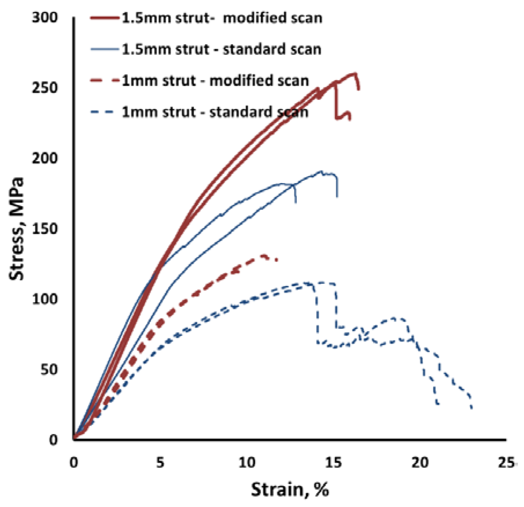
3.1. Modified Scan Strategy


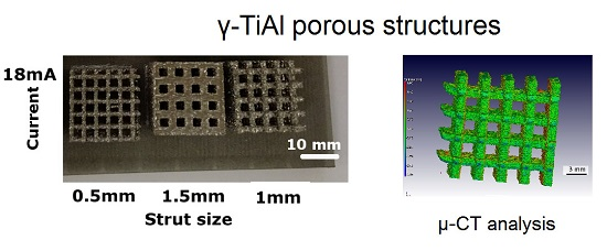
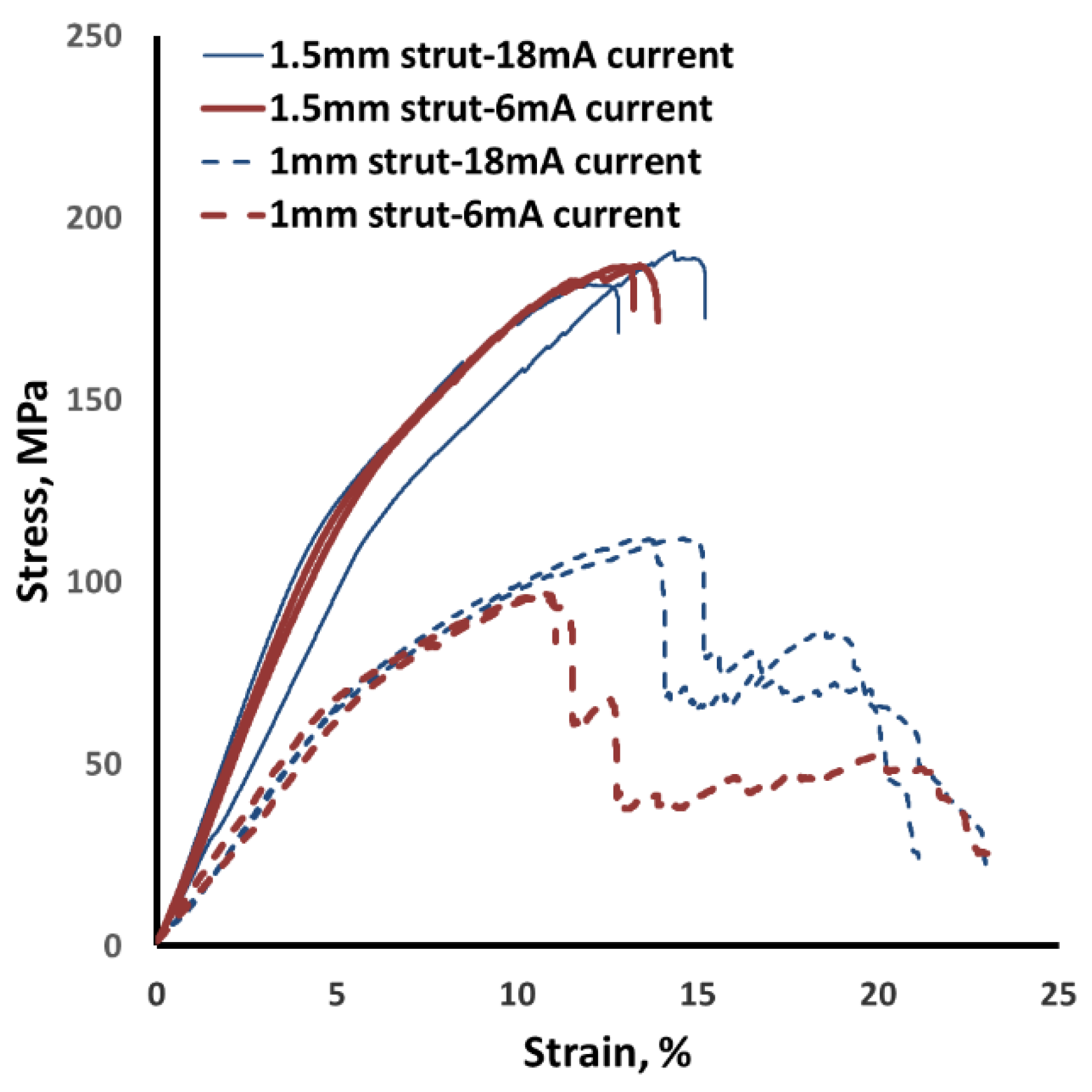
3.2. Effect of Beam Current

| Strut Thickness (mm) | Scan Strategy | Surface Area/Volume Ratio (mm−1) |
|---|---|---|
| 1 | Standard | 1.19 |
| 1 | Modified | 4.63 |
| 0.5 | Modified | 8.88 |

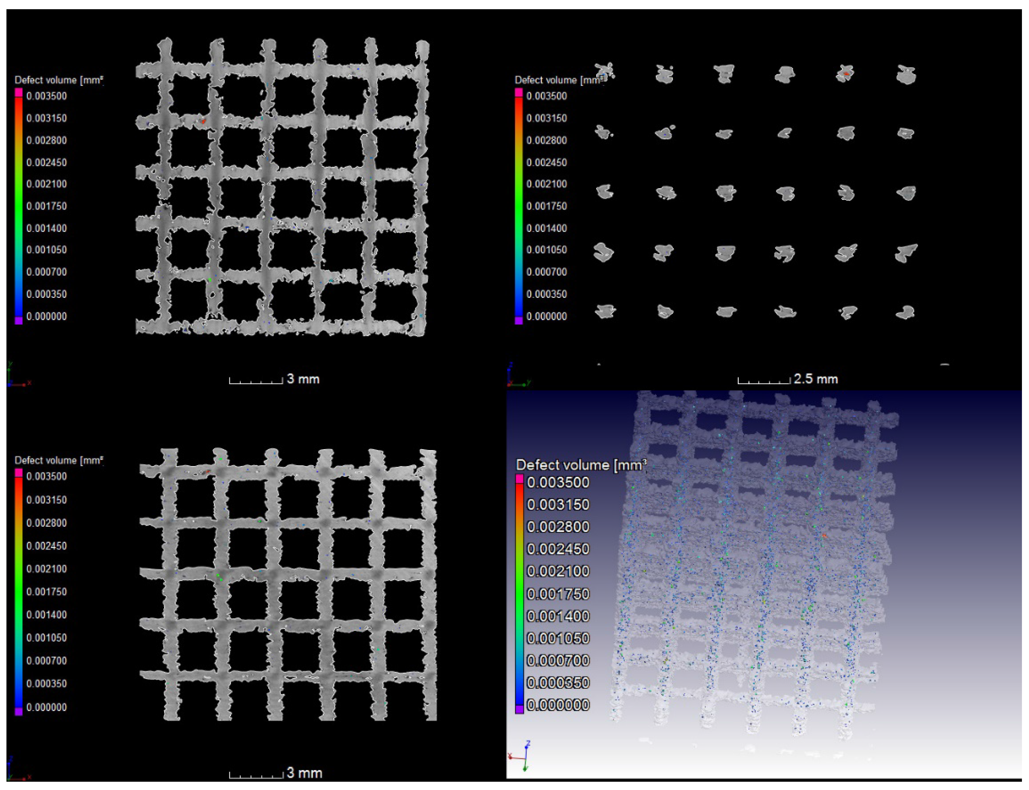
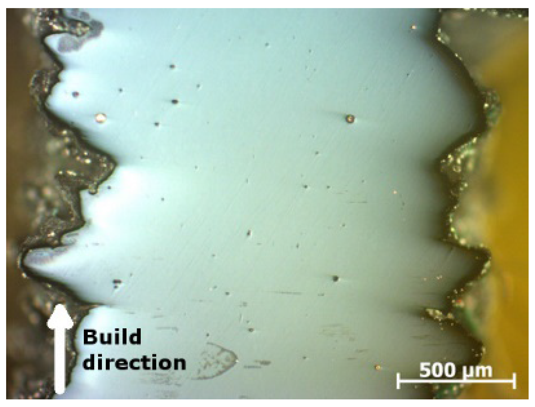
| Strut Thickness (mm) | Scan Strategy | Largest Internal Pore Diameter (mm) | Average Internal Porosity (vol. %) |
|---|---|---|---|
| 1 | Standard | 1.19 | 0.25 |
| 1 | Modified | 0.52 | 0.21 |
| 0.5 | Modified | 0.43 | 0.19 |
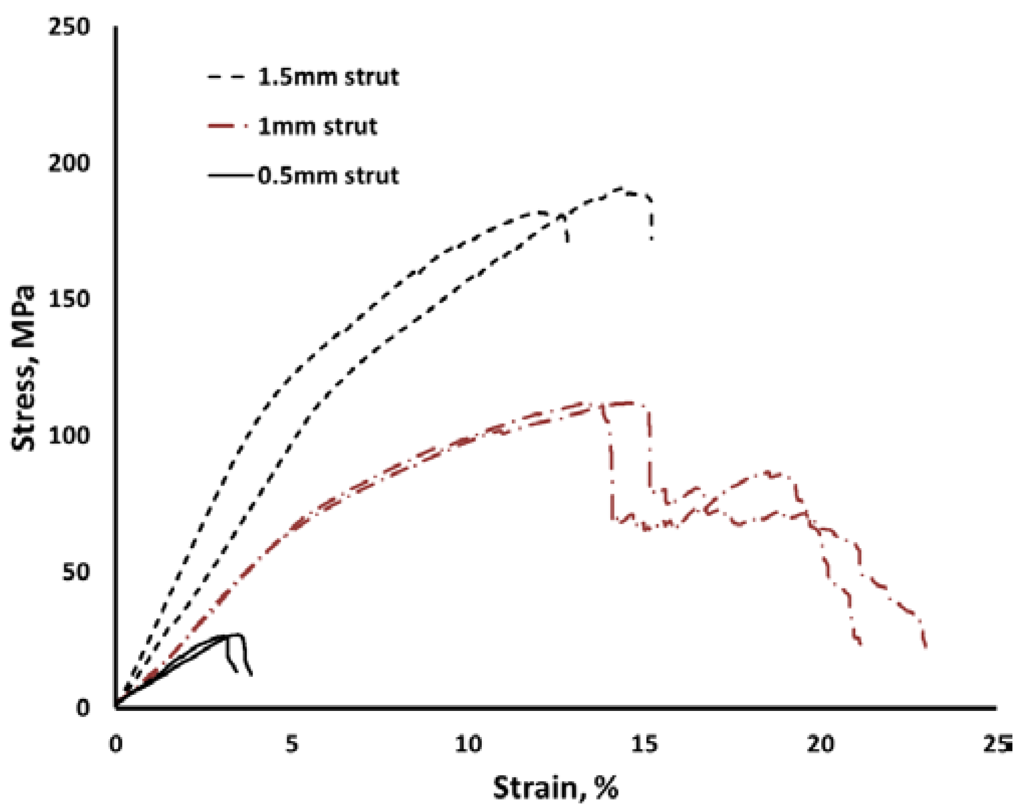
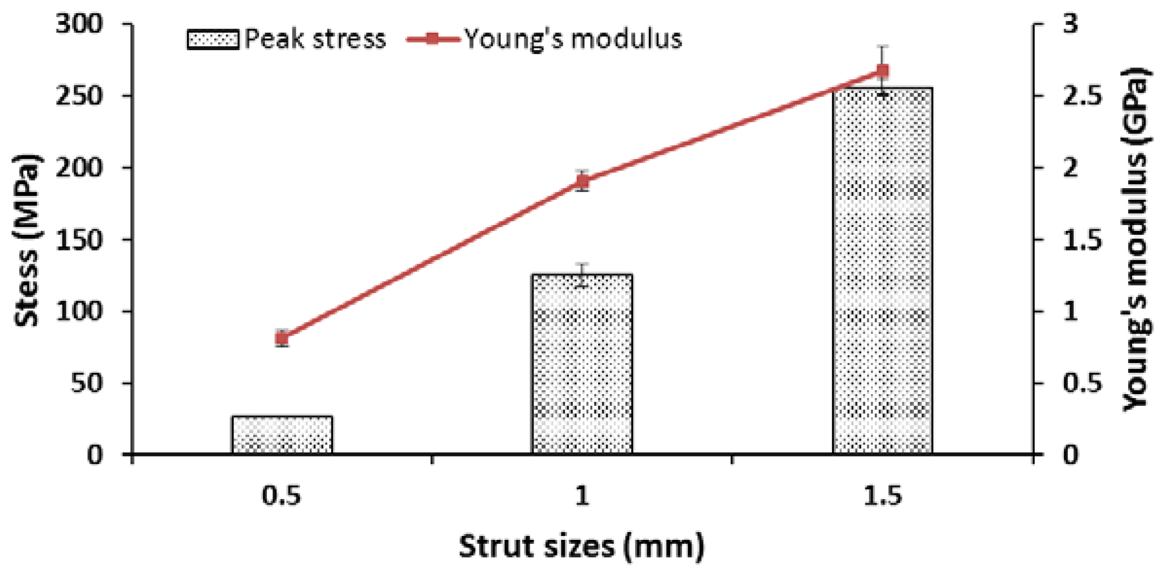
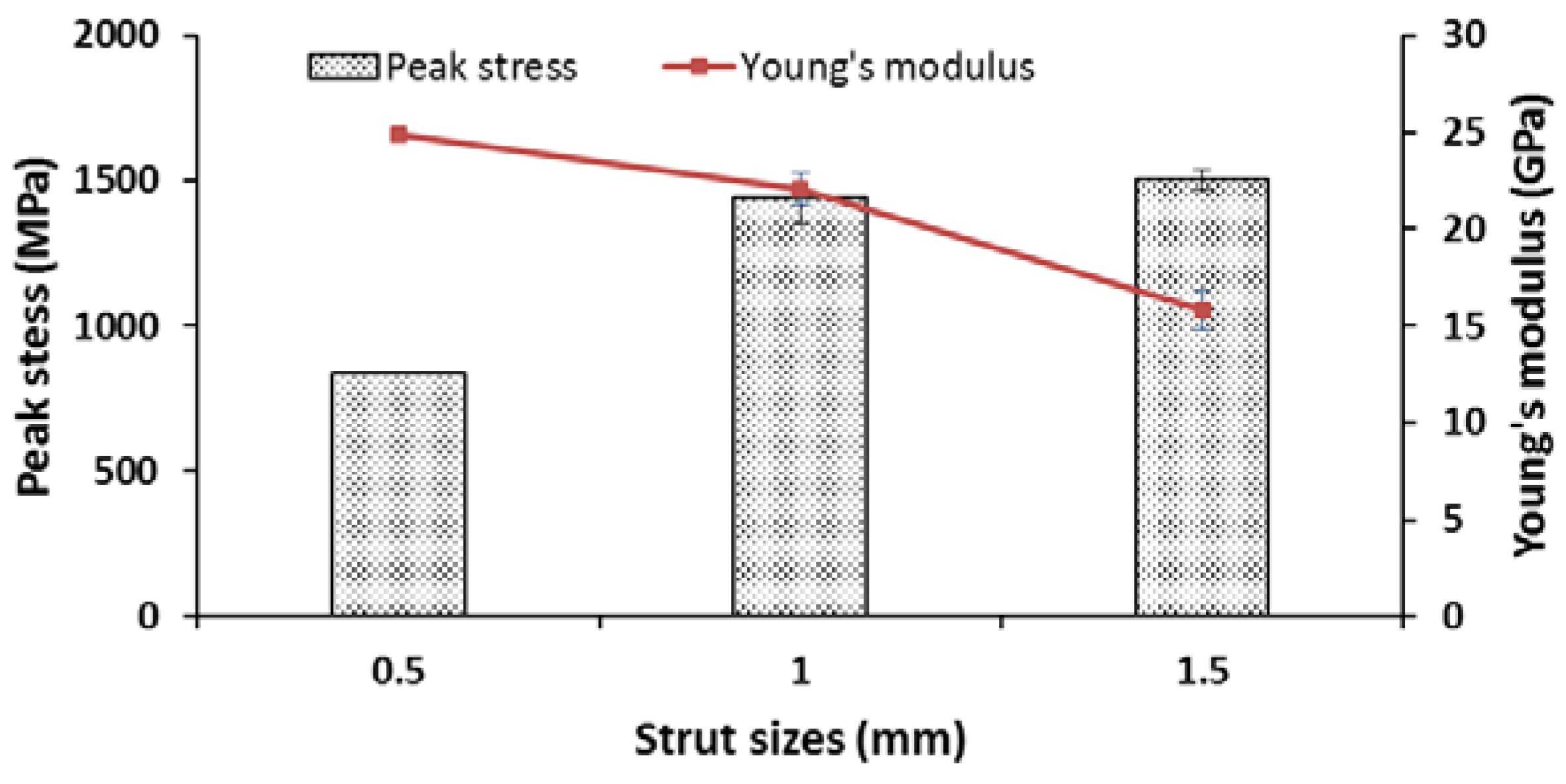
3.3. Compression Test
| Sample Number | Sample Conditions | Young’s Modulus (GPa) | Peak Compressive Stress σ (MPa) | ||
|---|---|---|---|---|---|
| Strut Size (mm) | Current (mA) | Scan Strategy | |||
| 1 | 1.5 | 18 | Standard | 2.39 ± 0.51 | 186 ± 6.22 |
| 2 | 1.5 | 12 | Standard | Not tested | Not tested |
| 3 | 1.5 | 6 | Standard | 2.59 ± 0.02 | 186 ± 0.20 |
| 4 | 1 | 18 | Standard | 1.46 ± 0.04 | 111 ± 0.07 |
| 5 | 1 | 12 | Standard | 1.71 ± 0.02 | 111 ± 1.07 |
| 6 | 1 | 6 | Standard | 1.35 ± 0.07 | 96 ± 0.71 |
| 7 | 0.5 | 18 | Standard | Build failed | Build failed |
| 8 | 0.5 | 12 | Standard | Build failed | Build failed |
| 9 | 0.5 | 6 | Standard | Build failed | Build failed |
| 10 | 1.5 | 18 | Modified | 2.67 ± 0.16 | 255 ± 5.59 |
| 13 | 1 | 18 | Modified | 1.91 ± 0.07 | 125 ± 7.76 |
| 16 | 0.5 | 18 | Modified | 0.81 ± 0.05 | 26 ± 0.33 |


4. Conclusions
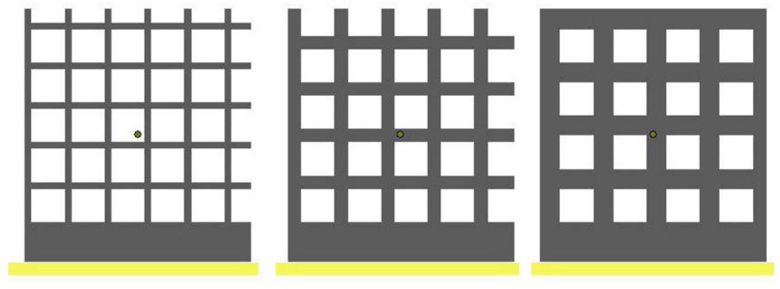
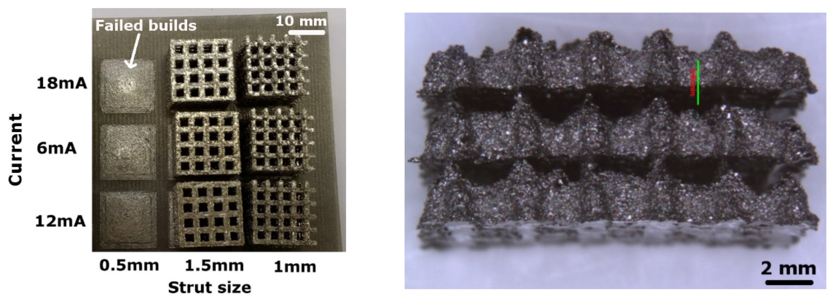
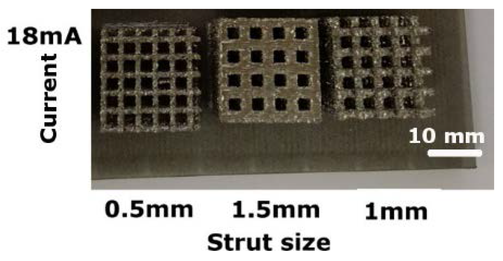
- The standard scan strategy (contour and hatch) produced all the struts except the 0.5 mm-thick ones, which failed because the scan strategy could not build the thin vertical struts. Even higher beam current could not create the 0.5 mm struts using this scan strategy.
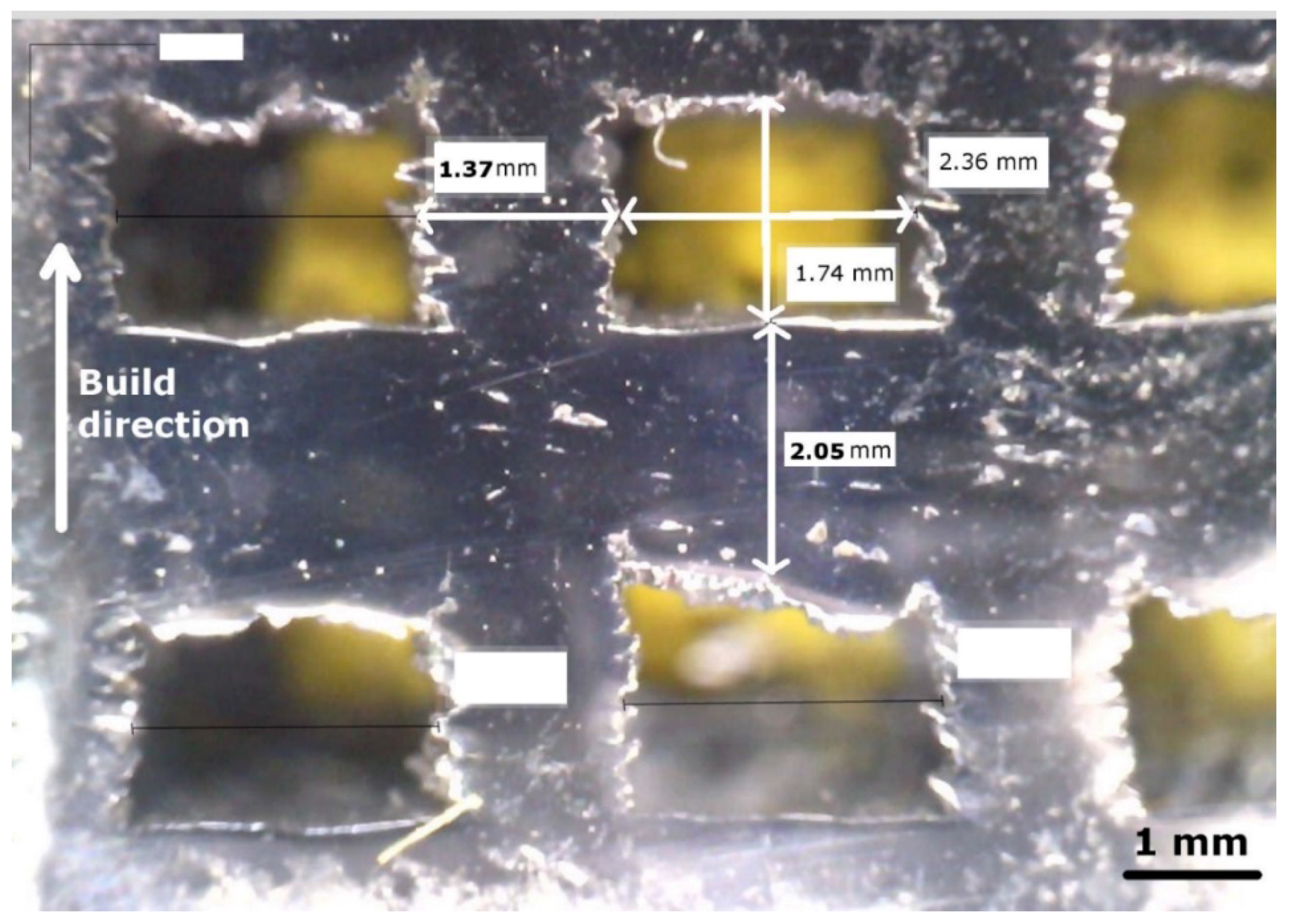
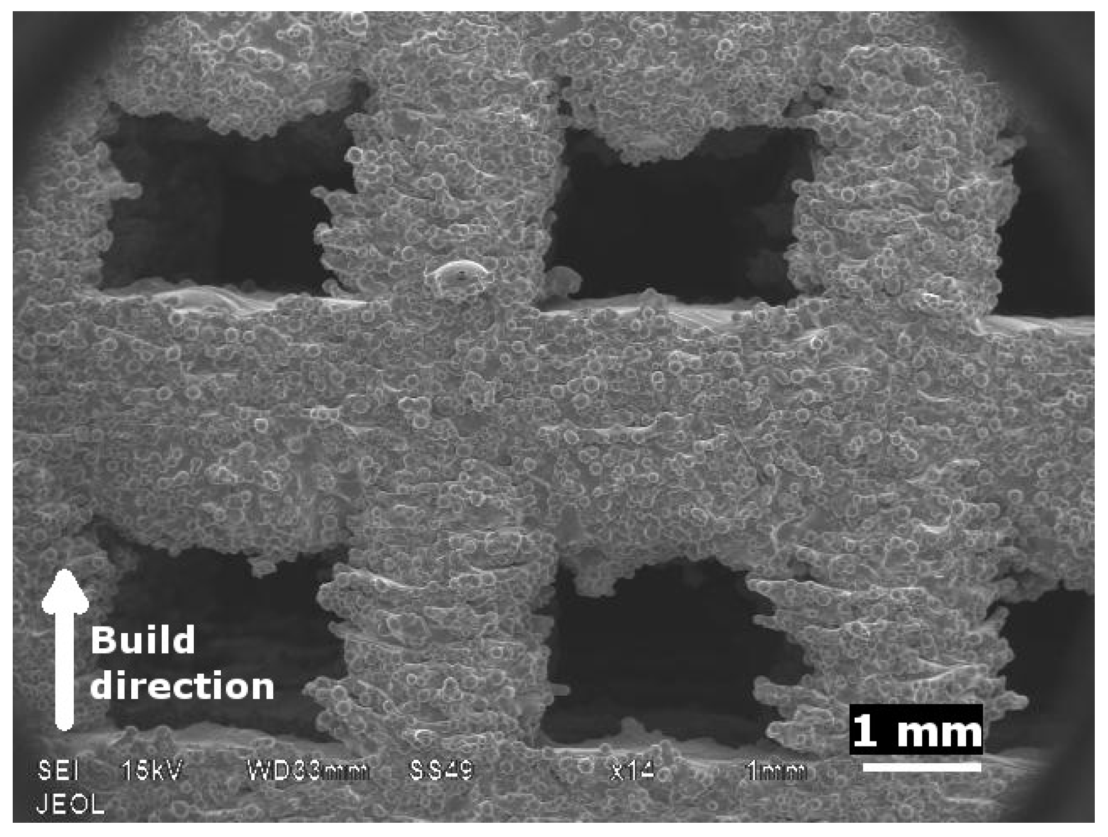
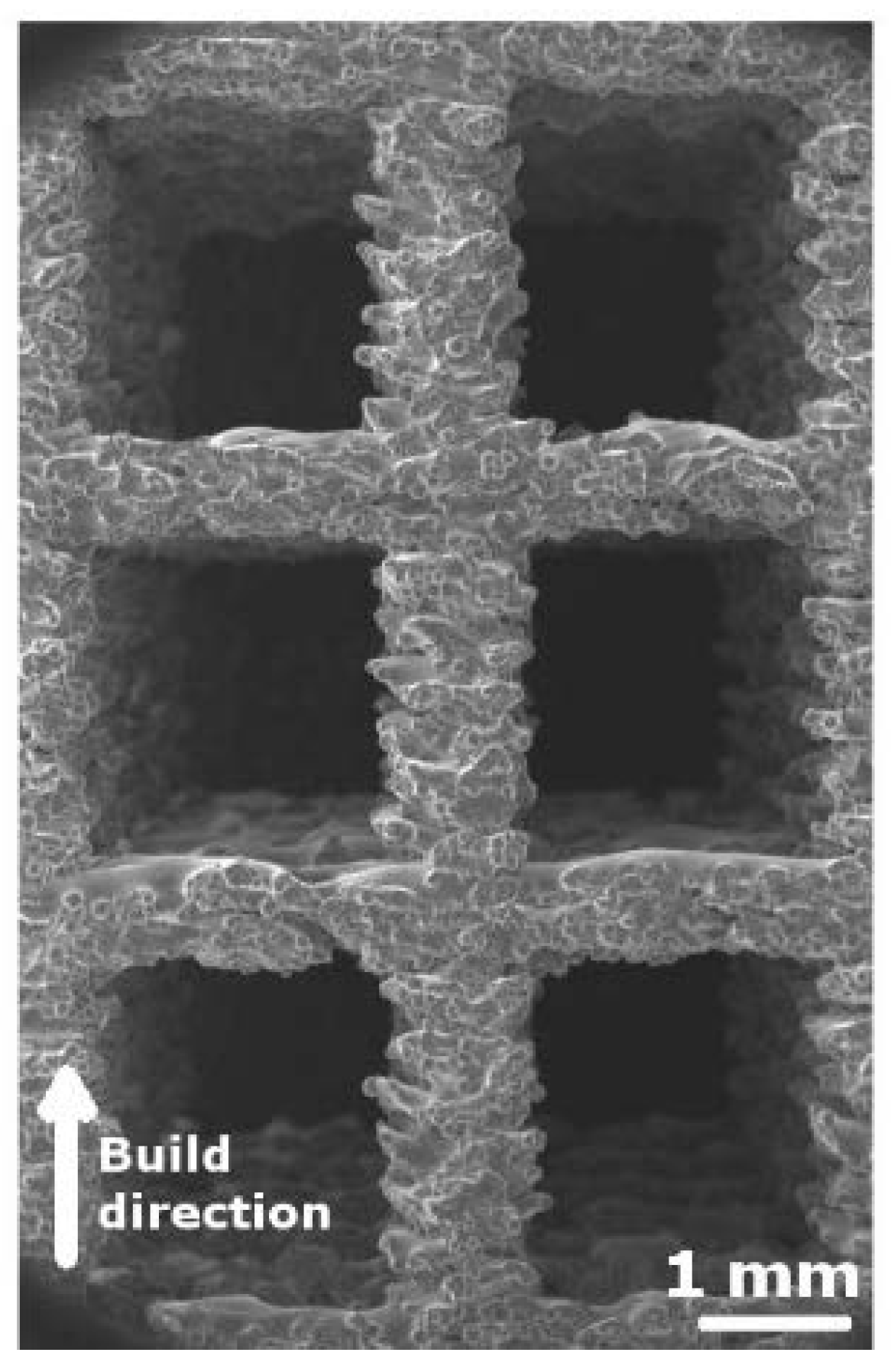
- With a standard scan strategy, powder sintered to the underside of the horizontal struts, making them bulkier than designed. The differences in thickness between the vertical and horizontal struts caused anisotropic pore shapes.
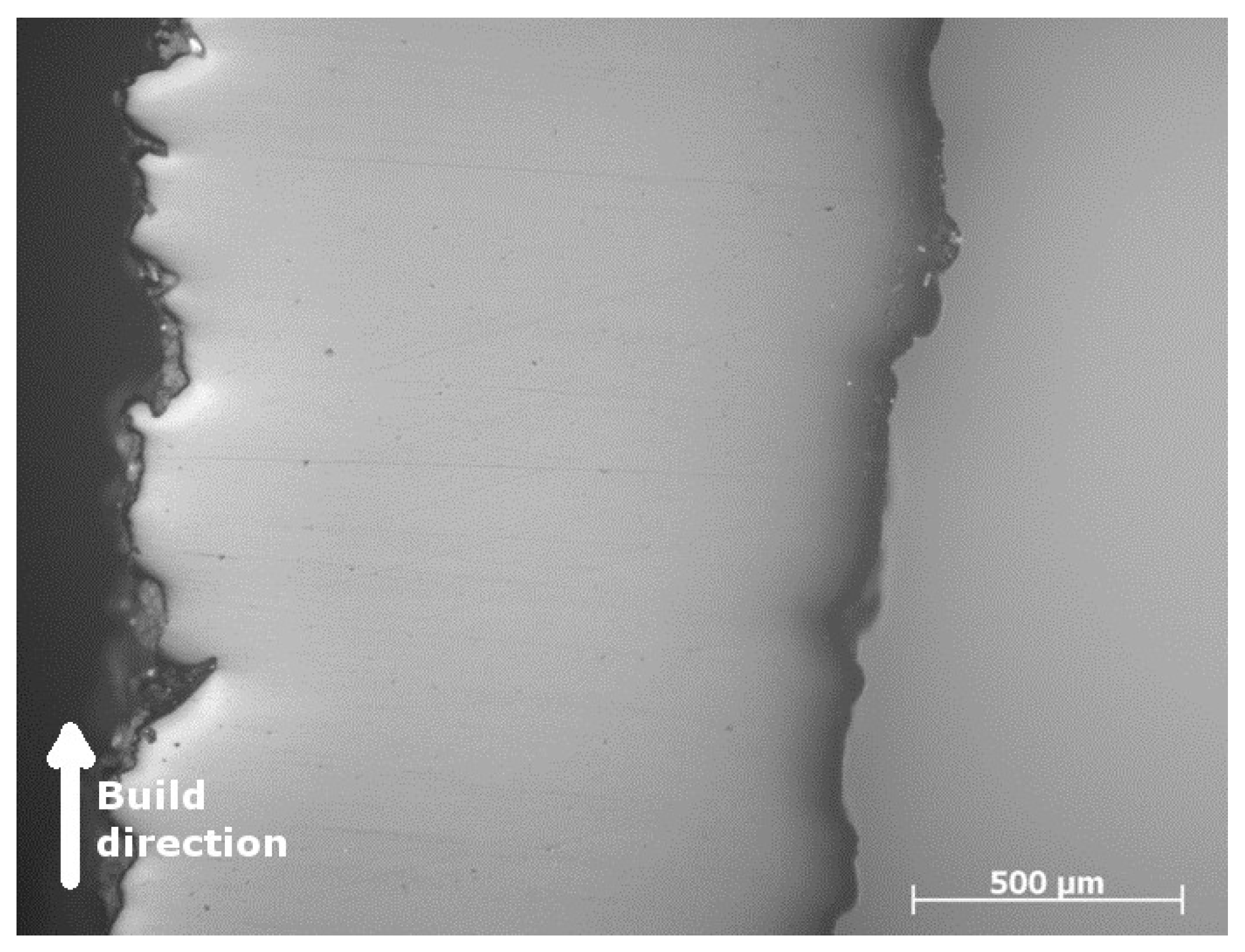
- A modified scan strategy (only hatching) produced 0.5 mm struts. This was possible because, in the modified scan strategy, the intense hatching beam imparted greater energy to the narrow regions required to build thin vertical struts.
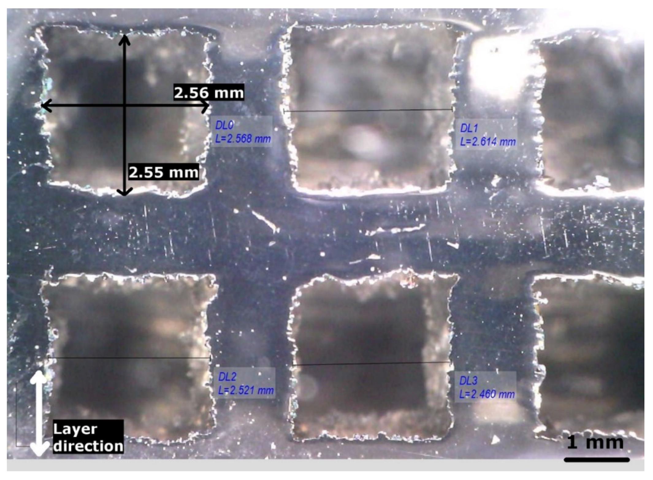
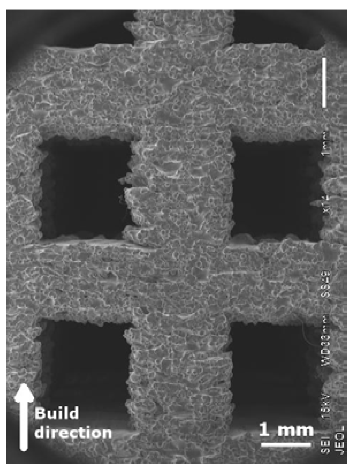
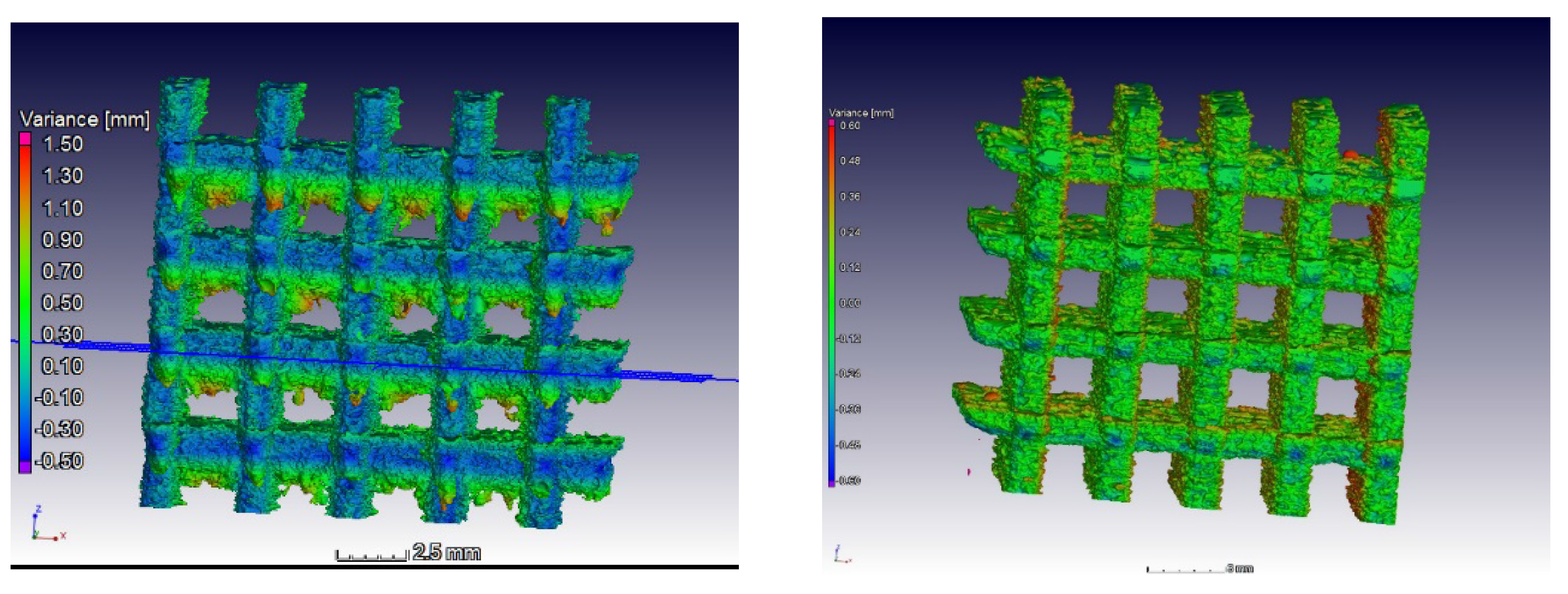
- The modified scan strategy gave better results than the standard strategy, even for thicker struts. The modified strategy reduced the amount of powder sintered to the bottoms of the horizontal struts which, in turn, produced pores closer to the design in all directions.
- The stiffness of the 0.5 mm strut structures was ~0.8 GPa, which is closer to the stiffness of a trabecular bone. Additionally, these fine structures had a decent peak stress of 26 MPa. Thus, by tuning the thicknesses of the struts and modifying the scan strategy, we could produce porous structures of γ-TiAl with the desired mechanical properties by using EBM. This attribute will play a critical role in manufacturing bio-implants specific to each patient.
Acknowledgments
Author Contributions
Conflicts of Interest
References
- Roy, S.; Panda, D.; Khutia, N.; Chowdhury, A.R.; Roy, S.; Panda, D.; Khutia, N.; Chowdhury, A.R. Pore geometry optimization of titanium (Ti6Al4V) alloy, for its application in the fabrication of customized hip implants. Int. J. Biomater. 2014. [Google Scholar] [CrossRef]
- Ikeo, N.; Ishimoto, T.; Fukuda, H.; Nakano, T. Fabrication and characterization of porous implant products with aligned pores by EBM method for biomedical application. Adv. Mater. Res. 2011, 409, 142–145. [Google Scholar] [CrossRef]
- Xiong, J.; Mines, R.; Ghosh, R.; Vaziri, A.; Ma, L.; Ohrndorf, A.; Christ, H.J.; Wu, L. Advanced micro-lattice materials. Adv. Eng. Mater. 2015, 17, 1253–1264. [Google Scholar] [CrossRef]
- Lv, J.; Jia, Z.; Li, J.; Wang, Y.; Yang, J.; Xiu, P.; Zhang, K.; Cai, H.; Liu, Z. Electron beam melting fabrication of porous Ti6Al4V scaffolds: Cytocompatibility and osteogenesis. Adv. Eng. Mater. 2015, 17, 1391–1398. [Google Scholar] [CrossRef]
- Murr, L.; Gaytan, S.; Martinez, E. Fabricating functional Ti-alloy biomedical implants by additive manufacturing using electron beam melting. J. Biotechnol. Biomater. 2012. [Google Scholar] [CrossRef]
- Parthasarathy, J.; Starly, B.; Raman, S.; Christensen, A. Mechanical evaluation of porous titanium (Ti6Al4V) structures with electron beam melting (EBM). J. Mech. Behav. Biomed. Mater. 2010, 3, 249–259. [Google Scholar] [CrossRef] [PubMed]
- Li, S.; Zhao, S.; Hou, W.; Teng, C.; Hao, Y.; Li, Y.; Yang, R.; Misra, R.D.K. Functionally graded Ti-6Al-4V meshes with high strength and energy absorption. Adv. Eng. Mater. 2016, 18, 34–38. [Google Scholar] [CrossRef]
- Martinez, E.; Murr, L.E.; Hernandez, J.; Pan, X.; Amato, K.; Frigola, P.; Terrazas, C.; Gaytan, S.; Rodriguez, E.; Medina, F.; et al. Microstructures of niobium components fabricated by electron beam melting. Metallogr. Microstruct. Anal. 2013, 2, 183–189. [Google Scholar] [CrossRef]
- Cormier, D.; Harrysson, O.; West, H. Characterization of H13 steel produced via electron beam melting. Rapid Prototyp. J. 2004, 10, 35–41. [Google Scholar] [CrossRef]
- Ramirez, D.A.; Murr, L.E.; Li, S.J.; Tian, Y.X.; Martinez, E.; Martinez, J.L.; Machado, B.I.; Gaytan, S.M.; Medina, F.; Wicker, R.B. Open-cellular copper structures fabricated by additive manufacturing using electron beam melting. Mater. Sci. Eng. A 2011, 528, 5379–5386. [Google Scholar] [CrossRef]
- Cormier, D.; Harrysson, O.; Mahale, T.; West, H. Freeform fabrication of titanium aluminide via electron beam melting using prealloyed and blended powders. Adv. Mater. Sci. Eng. 2008. [Google Scholar] [CrossRef]
- Aspinwall, D.K.; Dewes, R.C.; Mantle, A.L. The Machining of γ-TiAl intermetallic alloys. CIRP Ann. Manuf. Technol. 2005, 54, 99–104. [Google Scholar] [CrossRef]
- Tetsui, T.; Shindo, K.; Kaji, S.; Kobayashi, S.; Takeyama, M. Fabrication of TiAl components by means of hot forging and machining. Intermetallics 2005, 13, 971–978. [Google Scholar] [CrossRef]
- Rivera-Denizard, O.; Diffoot-Carlo, N.; Navas, V.; Sundaram, P.A. Biocompatibility studies of human fetal osteoblast cells cultured on gamma titanium aluminide. J. Mater. Sci. Mater. Med. 2008, 19, 153–158. [Google Scholar] [CrossRef] [PubMed]
- Santiago-Medina, P.; Sundaram, P.A.; Diffoot-Carlo, N. The effects of micro arc oxidation of gamma titanium aluminide surfaces on osteoblast adhesion and differentiation. J. Mater. Sci. Mater. Med. 2014, 25, 1577–1587. [Google Scholar] [CrossRef] [PubMed]
- Hernandez, J.; Murr, L.E.; Gaytan, S.M.; Martinez, E.; Medina, F.; Wicker, R.B. Microstructures for two-phase gamma titanium aluminide fabricated by electron beam melting. Metallogr. Microstruct. Anal. 2012, 1, 14–27. [Google Scholar] [CrossRef]
- Murr, L.E.; Esquivel, E.V.; Quinones, S.A.; Gaytan, S.M.; Lopez, M.I.; Martinez, E.Y.; Medina, F.; Hernandez, D.H.; Martinez, E.; Martinez, J.L.; et al. Microstructures and mechanical properties of electron beam-rapid manufactured Ti-6Al-4V biomedical prototypes compared to wrought Ti-6Al-4V. Mater. Charact. 2009, 60, 96–105. [Google Scholar] [CrossRef]
- Arabnejad, S.; Johnston, R.B.; Pura, J.A.; Singh, B.; Tanzer, M.; Pasini, D. High-strength porous biomaterials for bone replacement: A strategy to assess the interplay between cell morphology, mechanical properties, bone ingrowth and manufacturing constraints. Acta Biomater. 2016, 30, 345–356. [Google Scholar] [CrossRef] [PubMed]
- Attar, E. Simulation of Selective Electron Beam Melting Processes; VDM Publishing: Saarbrücken, Germany, 2011. [Google Scholar]
- Shen, N.; Chou, K. Thermal modeling of electron beam additive manufacturing process: Powder sintering effects. In Proceedings of the ASME 2012 International Manufacturing Science and Engineering Conference, Notre Dame, IN, USA, 4–8 June 2012; pp. 287–295.
- Arce, A.N. Thermal Modeling and Simulation of Electron Beam Melting For Rapid Prototyping on Ti6Al4V Alloys; North Carolina State University: Raleigh, NC, USA, 2013. [Google Scholar]
- Heinl, P.; Müller, L.; Körner, C.; Singer, R.F.; Müller, F.A. Cellular Ti-6Al-4V structures with interconnected macro porosity for bone implants fabricated by selective electron beam melting. Acta Biomater. 2008, 4, 1536–1544. [Google Scholar] [CrossRef] [PubMed]
- Körner, C.; Attar, E.; Heinl, P. Mesoscopic simulation of selective beam melting processes. J. Mater. Process. Technol. 2011, 211, 978–987. [Google Scholar] [CrossRef]
- Kothari, K.; Radhakrishnan, R.; Sudarshan, T.S.; Wereley, N.M. Characterization of rapidly consolidated γ-TiAl. Adv. Mater. Res. 2012, 1, 51–74. [Google Scholar] [CrossRef]
- Biamino, S.; Penna, A.; Ackelid, U.; Sabbadini, S.; Tassa, O.; Fino, P.; Pavese, M.; Gennaro, P.; Badini, C. Electron beam melting of Ti-48Al-2Cr-2Nb alloy: Microstructure and mechanical properties investigation. Intermetallics 2011, 19, 776–781. [Google Scholar] [CrossRef]
- Feller, L.; Jadwat, Y.; Khammissa, R.A.G.; Meyerov, R.; Schechter, I.; Lemmer, J.; Feller, L.; Jadwat, Y.; Khammissa, R.A.G.; Meyerov, R.; et al. Cellular responses evoked by different surface characteristics of intraosseous titanium implants. BioMed Res. Int. 2015. [Google Scholar] [CrossRef] [PubMed]
- Hernández-Nava, E.; Smith, C.J.; Derguti, F.; Tammas-Williams, S.; Léonard, F.; Withers, P.J.; Todd, I.; Goodall, R. The effect of density and feature size on mechanical properties of isostructural metallic foams produced by additive manufacturing. Acta Mater. 2015, 85, 387–395. [Google Scholar] [CrossRef]
- Li, X.; Wang, C.; Zhang, W.; Li, Y. Fabrication and characterization of porous Ti6Al4V parts for biomedical applications using electron beam melting process. Mater. Lett. 2009, 63, 403–405. [Google Scholar] [CrossRef]
- Wauthle, R.; Ahmadi, S.M.; Yavari, S.A.; Mulier, M.; Zadpoor, A.A.; Weinans, H.; van Humbeeck, J.; Kruth, J.P.; Schrooten, J. Revival of pure titanium for dynamically loaded porous implants using additive manufacturing. Mater. Sci. Eng. C Mater. Biol. Appl. 2015, 54, 94–100. [Google Scholar] [CrossRef] [PubMed]
- Allison, P.G.; Horstemeyer, M.F.; Brown, H.R. Modulus dependence on large scale porosity of powder metallurgy steel. J. Mater. Eng. Perform. 2012, 21, 1422–1425. [Google Scholar] [CrossRef]
- Choren, J.A.; Heinrich, S.M.; Silver-Thorn, M.B. Young’s modulus and volume porosity relationships for additive manufacturing applications. J. Mater. Sci. 2013, 48, 5103–5112. [Google Scholar] [CrossRef]
© 2016 by the authors; licensee MDPI, Basel, Switzerland. This article is an open access article distributed under the terms and conditions of the Creative Commons by Attribution (CC-BY) license (http://creativecommons.org/licenses/by/4.0/).
Share and Cite
Mohammad, A.; Alahmari, A.M.; Moiduddin, K.; Mohammed, M.K.; Alomar, A.; Renganayagalu, R.K. Porous γ-TiAl Structures Fabricated by Electron Beam Melting Process. Metals 2016, 6, 25. https://doi.org/10.3390/met6010025
Mohammad A, Alahmari AM, Moiduddin K, Mohammed MK, Alomar A, Renganayagalu RK. Porous γ-TiAl Structures Fabricated by Electron Beam Melting Process. Metals. 2016; 6(1):25. https://doi.org/10.3390/met6010025
Chicago/Turabian StyleMohammad, Ashfaq, Abdulrahman M. Alahmari, Khaja Moiduddin, Muneer Khan Mohammed, Abdulrahman Alomar, and Ravi Kottan Renganayagalu. 2016. "Porous γ-TiAl Structures Fabricated by Electron Beam Melting Process" Metals 6, no. 1: 25. https://doi.org/10.3390/met6010025