
Corrosion Behavior in 3.5% NaCl Solutions of γ-TiAl Processed by Electron Beam Melting Process

 ,
,  and
and
Abstract
:
1. Introduction
2. Experimental Procedure
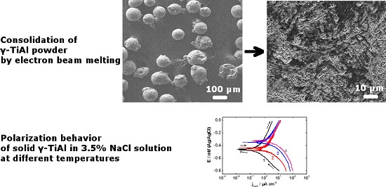
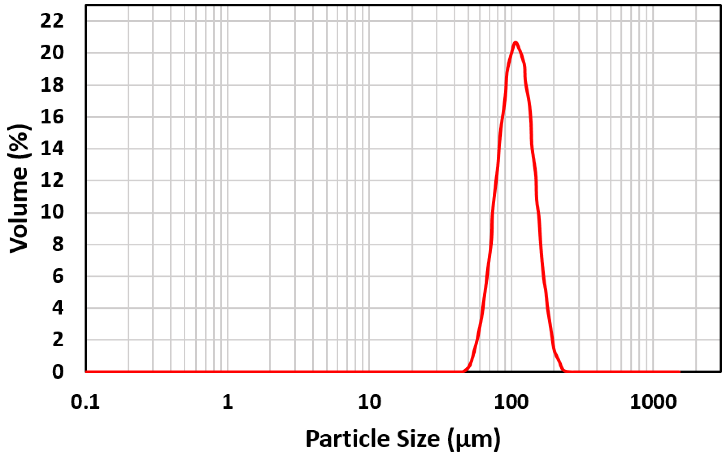
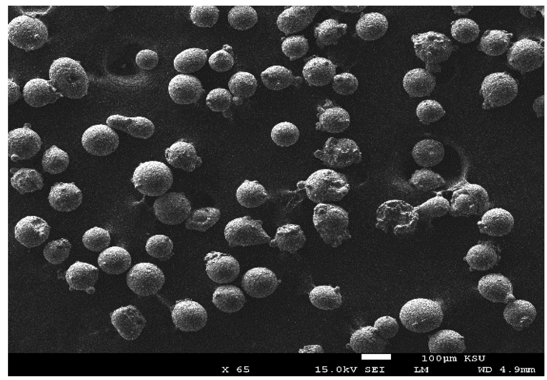
2.1. Production of Ti Aluminide Alloy


2.2. Chemicals, Materials, and Electrochemical Cell
2.3. Potentiodynamic Polarization and Electrochemical Impedance (EIS)
2.4. Surface Characterization
3. Results and Discussion
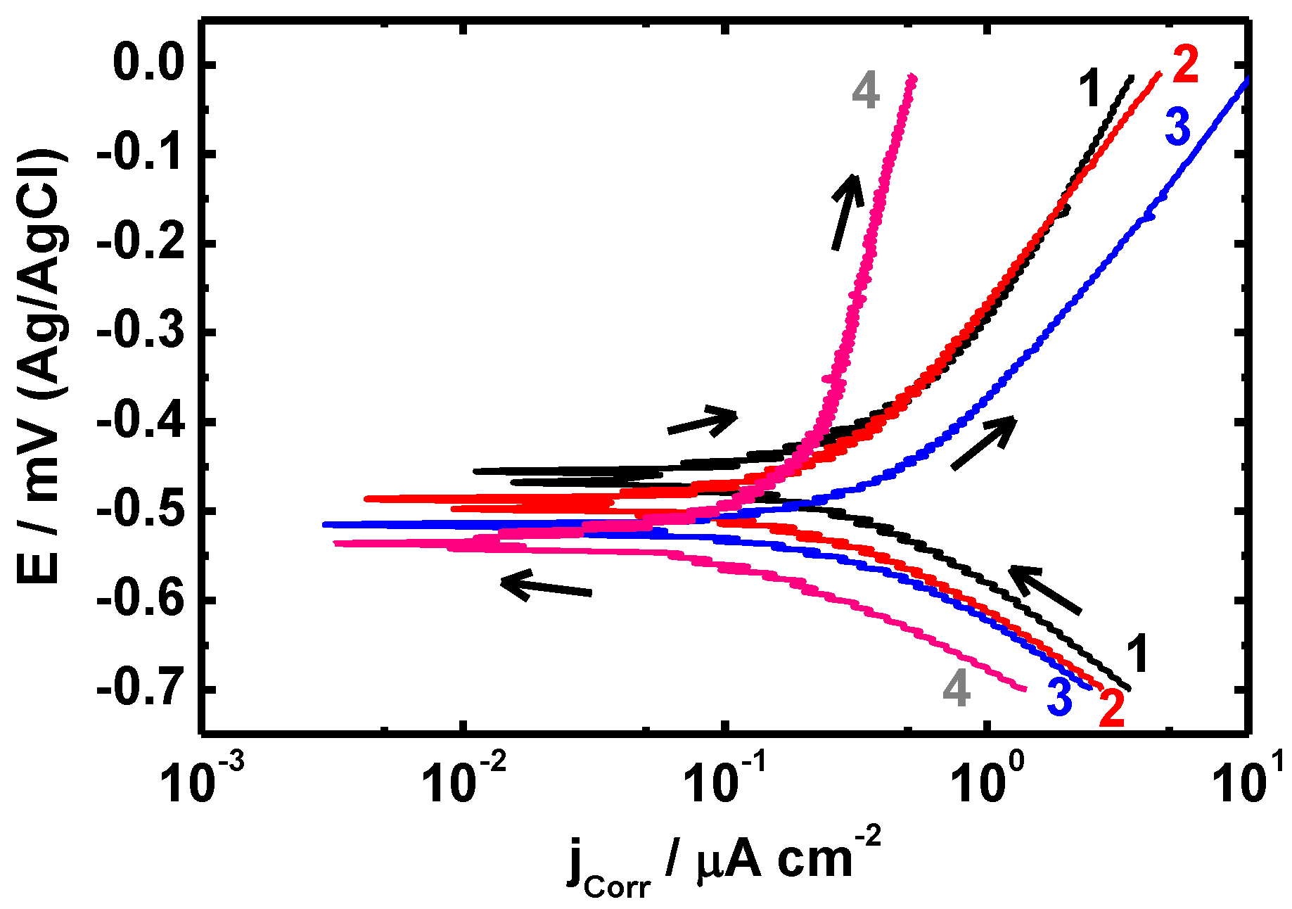
3.1. Potentiodynamic Polarization Measurements

| Exposure Period/h | Parameter | ||||
|---|---|---|---|---|---|
| βa/mV·dec−1 | βc/mV·dec−1 | ECorr/mV | jCorr/µA·cm−2 | Rp/kΩ·cm2 | |
| 0 | 65.66 | 72.81 | −497 | 0.157 | 255.9 |
| 1 | 62.21 | 74.95 | −538 | 0.102 | 339.7 |
| 4 | 60.83 | 70.75 | −591 | 0.076 | 368.3 |
| 24 | 65.02 | 74.34 | −595 | 0.074 | 440.8 |

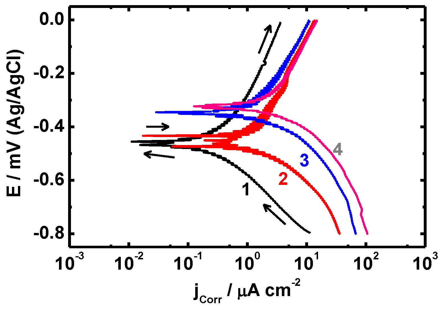
| Temperature/°C | Parameter | ||||
|---|---|---|---|---|---|
| βa/mV·dec−1 | βc/mV·dec−1 | ECorr/mV | jCorr/µA·cm−2 | Rp/kΩ·cm2 | |
| 20 | 65.66 | 72.81 | −497 | 0.10 | 255.9 |
| 30 | 66.91 | 74.74 | −438 | 0.25 | 166.7 |
| 40 | 60.78 | 74.09 | −356 | 0.35 | 105.8 |
| 50 | 61.33 | 70.82 | −330 | 0.44 | 70.88 |
| 60 | 64.37 | 73.85 | −322 | 0.73 | 50.93 |
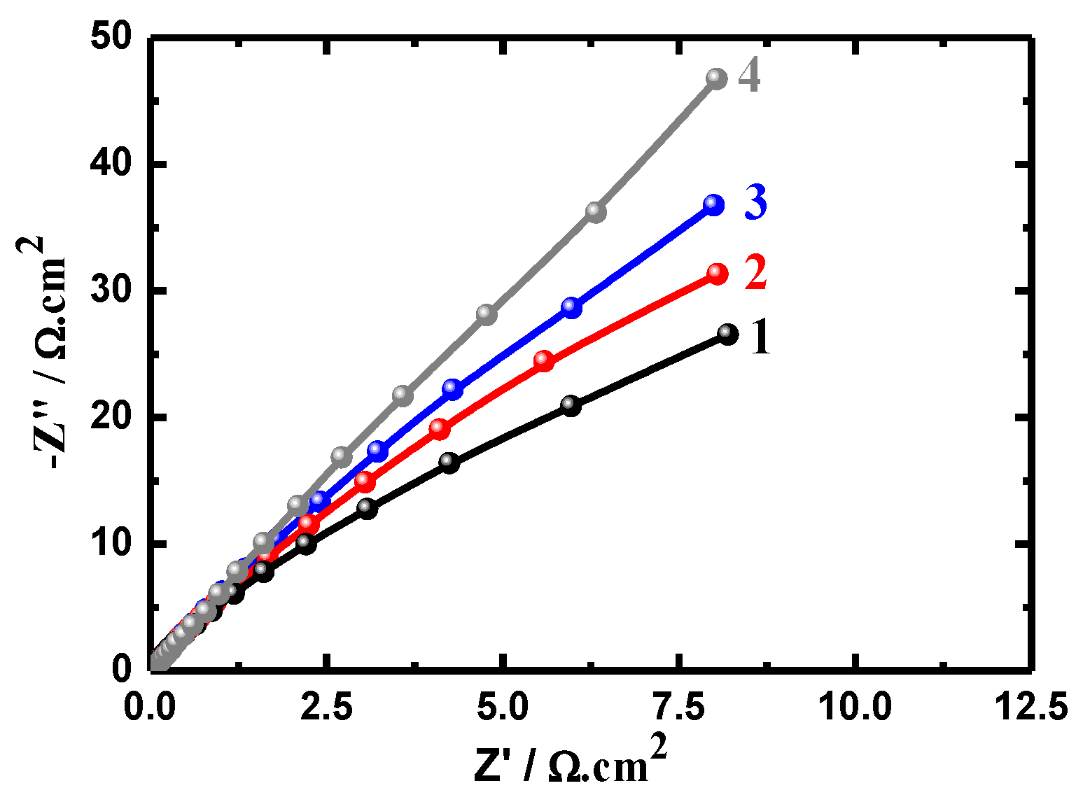
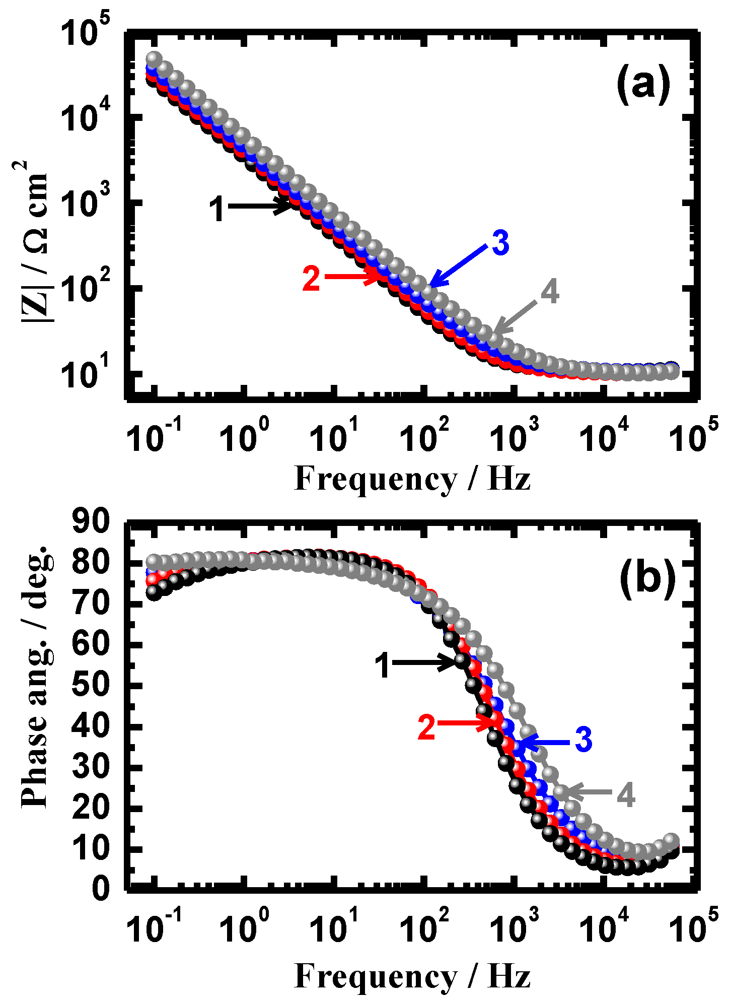
3.2. Electrochemical Impedance Spectroscopy (EIS)

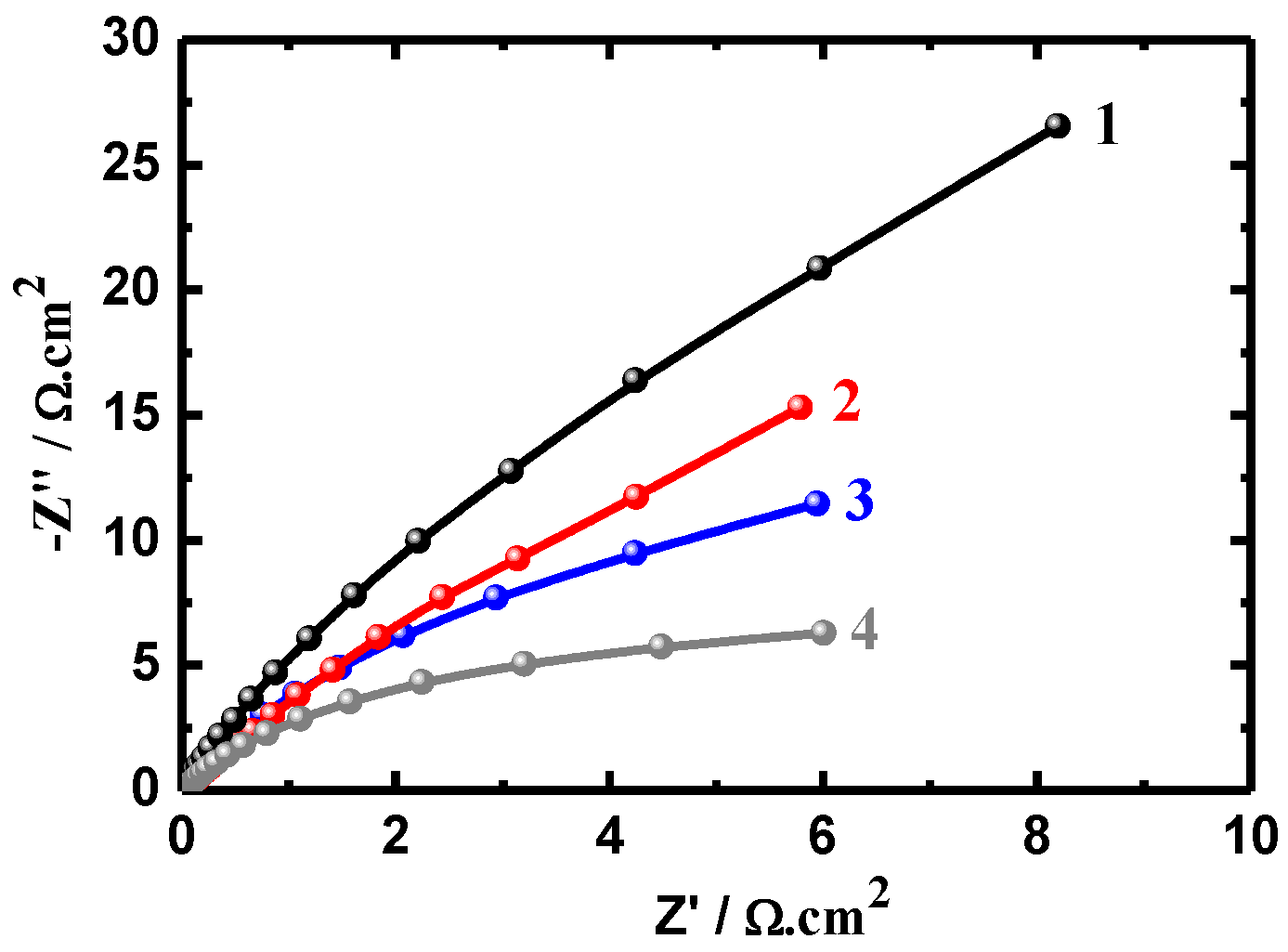
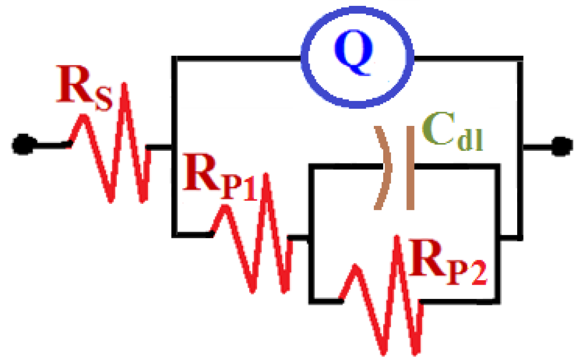
| Exposure Period/h | RS/Ω·cm2 | Q | RP1/Ω·cm2 | Cdl/F·cm−2 | RP2/Ω·cm2 | |
|---|---|---|---|---|---|---|
| YQ/F·cm−2 | n | |||||
| 0 | 9.22 | 0.3251 | 0.73 | 4.83 | 0.2992 | 15.82 |
| 1 | 9.83 | 0.2978 | 0.86 | 6.44 | 0.2814 | 21.13 |
| 4 | 9.99 | 0.2641 | 0.84 | 14.2 | 0.2656 | 25.35 |
| 24 | 10.03 | 0.2489 | 0.89 | 19.7 | 0.2115 | 37.57 |
| Temperature/°C | RS/Ω·cm2 | Q | RP1/Ω·cm2 | Cdl/F·cm−2 | RP2/Ω·cm2 | |
|---|---|---|---|---|---|---|
| YQ/F·cm−2 | n | |||||
| 20 | 9.22 | 0.325 | 0.73 | 4.83 | 0.2992 | 15.82 |
| 30 | 8.99 | 0.338 | 0.83 | 4.36 | 0.3199 | 12.13 |
| 40 | 8.42 | 0.345 | 0.85 | 3.50 | 0.3537 | 9.38 |
| 50 | 8.35 | 0.383 | 0.87 | 2.99 | 0.3735 | 7.59 |
| 60 | 8.12 | 0.394 | 0.89 | 2.06 | 0.4849 | 5.94 |
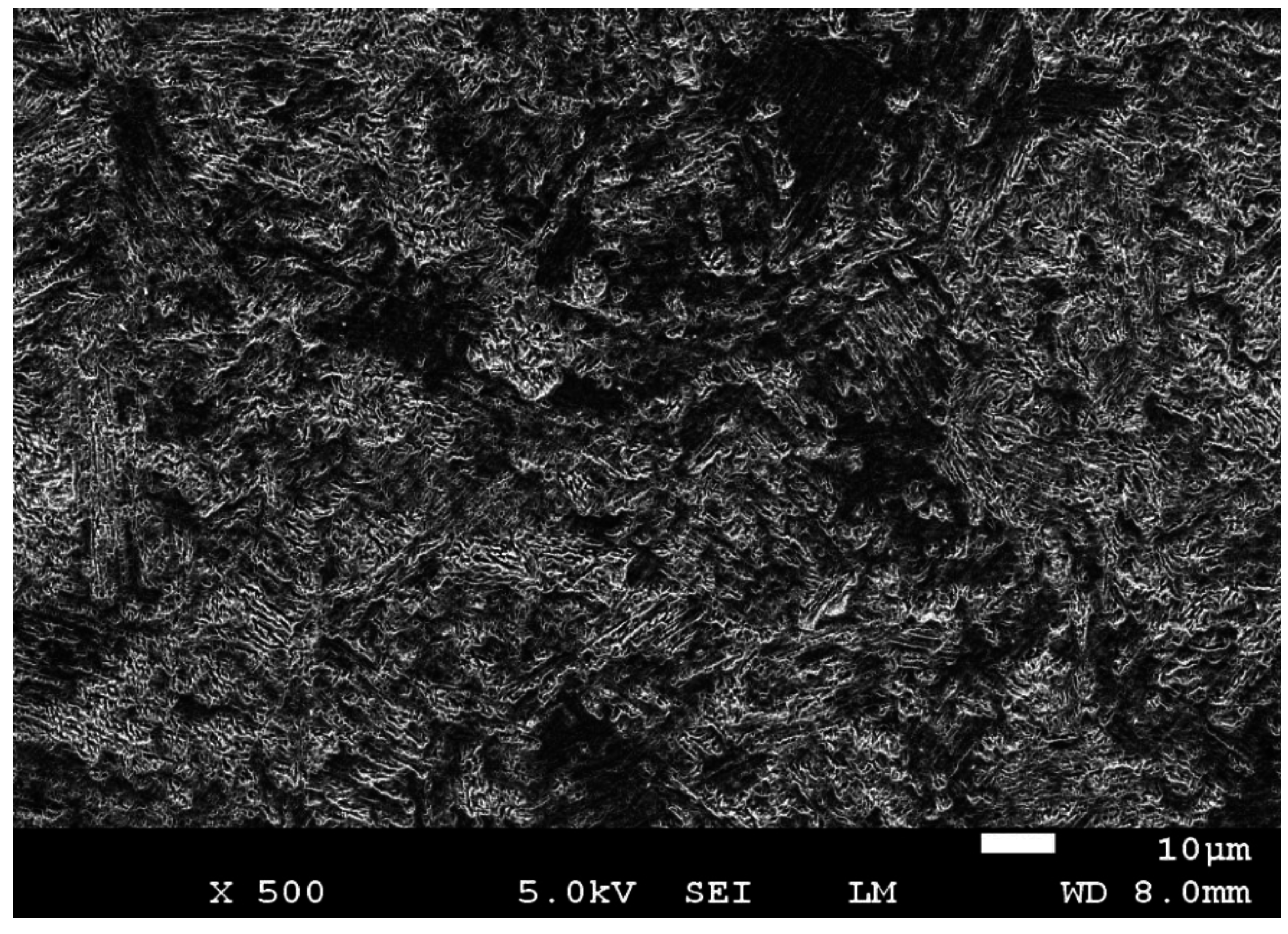
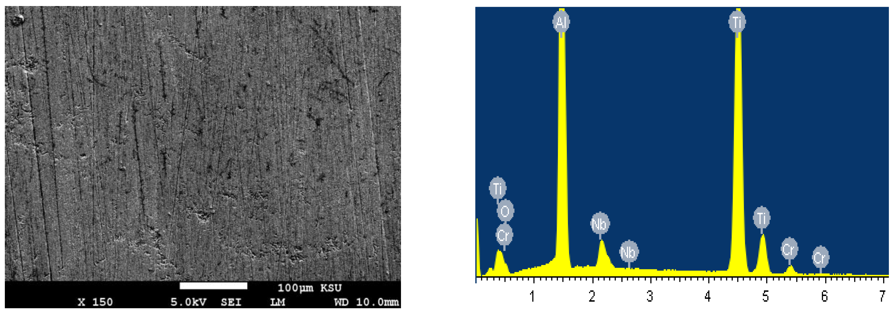
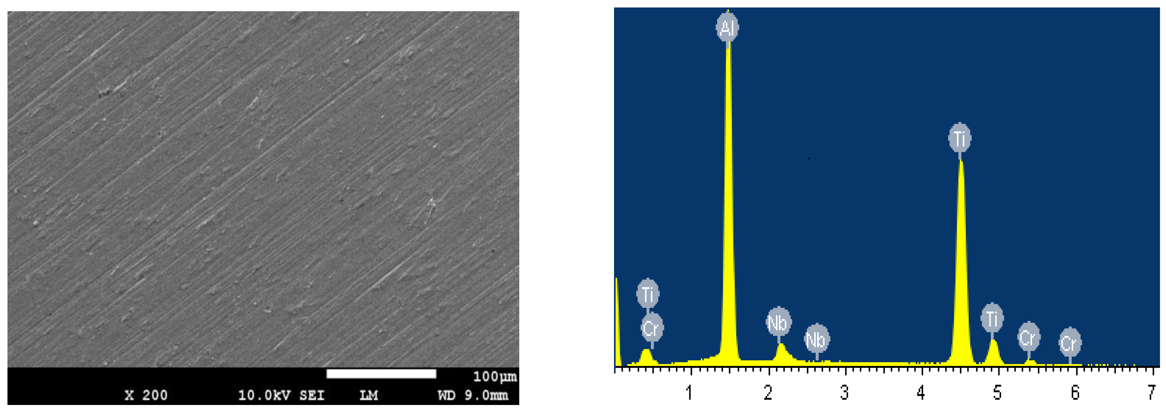
3.3. Scanning Electron Microscopy (SEM) and Energy Dispersive X-ray (EDX) Analyses

4. Conclusions
Acknowledgments
Author Contributions
Conflicts of Interest
References
- Murr, L.E.; Gaytan, S.M.; Ceylan, A.; Martinez, E.; Martinez, J.L.; Hernandez, D.H.; Machado, B.I.; Ramirez, D.A.; Medina, F.; Collins, S.; et al. Characterization of titanium aluminide alloy components fabricated by additive manufacturing using electron beam melting. Acta Mater. 2010, 58, 1887–1894. [Google Scholar] [CrossRef]
- Donachie, M.J., Jr. Titanium—A Technical Guide; ASM International: Geauga County, OH, USA, 2000. [Google Scholar]
- Wu, X. Review of alloy and process development of TiAl alloys. Intermetallics 2006, 14, 1114–1122. [Google Scholar] [CrossRef]
- Draper, L.S.; Das, G.; Locci, I.; Whittenberger, J.D.; Lerch, B.A.; Kestler, H. Gamma Titanium Alumindes; Kim, Y.-W., Clemens, H., Rosenberger, A.H., Eds.; TMS: Warrendale, PA, USA, 2003; pp. 207–212. [Google Scholar]
- Liu, X.; Chu, P.; Ding, C. Surface modification of titanium, titanium alloys, and related materials for biomedical applications. Mater. Sci. Eng. R 2004, 47, 49–121. [Google Scholar] [CrossRef]
- Tetsui, T.; Shindo, K.; Kaji, S.; Kobayashi, S.; Takeyama, M. Fabrication of TiAl components by means of hot forging and machining. Intermetallics 2005, 13, 971–978. [Google Scholar] [CrossRef]
- Tetsui, T.; Shindo, K.; Kaji, S.; Kobayashi, S.; Takeyama, M. Strengthening a high-strength TiAl alloy by hot-forging. Intermetallics 2003, 11, 299–306. [Google Scholar] [CrossRef]
- Wegmann, G.; Gerling, R.; Schimansky, F.P.; Clemens, H.; Bartels, A. High-temperature mechanical properties of hot isostatically pressed and forged gamma titanium aluminide alloy powder. Intermetallics 2002, 10, 511–517. [Google Scholar] [CrossRef]
- Kuang, J.P.; Harding, R.A.; Campbell, J. Microstructures and properties of investment castings of γ-titanium aluminide. Mater. Sci. Eng. A 2002, 329–331, 31–37. [Google Scholar] [CrossRef]
- Delgado-Alvarado, C.; Sundaram, P.A. Corrosion evaluation of Ti-48Al-2Cr-2Nb (at. %) in Ringer’s solution. Acta Biomater. 2006, 2, 701–708. [Google Scholar] [CrossRef] [PubMed]
- Gurrapa, I. Degradation of Ti-24Al-15Nb alloys under different environmental conditions. Intermetallics 2003, 11, 867–871. [Google Scholar] [CrossRef]
- Sherif, E.-S.M.; Almajid, A.A.; Latif, F.H.; Junaedi, H. Effects of Graphite on the Corrosion Behavior of Aluminum-Graphite Composite in Sodium Chloride Solutions. Int. J. Electrochem. Sci. 2011, 6, 1085–1099. [Google Scholar]
- Latief, F.H.; Sherif, E.-S.M.; Almajid, A.A.; Junaedi, H. Fabrication of exfoliated graphite nanoplatelets-reinforced aluminum composites and evaluating their mechanical properties and corrosion behavior. J. Anal. Appl. Pyrolysis 2011, 92, 485–492. [Google Scholar] [CrossRef]
- Sherif, E.-S.M. Corrosion and Corrosion Inhibition of Aluminum in Arabian Gulf Seawater and Sodium Chloride Solutions by 3-Amino-5-Mercapto-1,2,4-Triazole. Int. J. Electrochem. Sci. 2011, 6, 1479–1492. [Google Scholar]
- Latief, F.H.; Sherif, E.-S.M.; Kakehi, K. Role of Aluminide Coating on Oxidation Resistance of Ni-Based Single Crystal Superalloy at 900 °C. Int. J. Electrochem. Sci. 2015, 10, 1873–1882. [Google Scholar]
- Zubaidy, E.A.H.A.; Mohammad, F.S.; Bassioni, G. Effect of pH, Salinity and Temperature on Aluminum Cookware Leaching during Food Preparation. Int. J. Electrochem. Sci. 2011, 6, 6424–6441. [Google Scholar]
- Darowicki, K.; Krakowiak, S.; Ślepski, P. Evaluation of pitting corrosion by means of dynamic electrochemical impedance spectroscopy. Electrochim. Acta 2004, 49, 2909–2918. [Google Scholar] [CrossRef]
- Floyd, F.L.; Avudaiappan, S.; Gibson, J.; Mehta, B.; Smith, P.; Provder, T.; Escarsega, J. Using electrochemical impedance spectroscopy to predict the corrosion resistance of unexposed coated metal panels. Prog. Org. Coatings 2009, 66, 8–34. [Google Scholar] [CrossRef]
- Sherif, E.-S.M. Electrochemical investigations on the corrosion inhibition of aluminum by 3-amino-1,2,4-triazole-5-thiol in naturally aerated stagnant seawater. J. Ind. Eng. Chem. 2013, 19, 1884–1889. [Google Scholar] [CrossRef]
- Sherif, E.-S.M.; Abdo, H.S.; Khalil, K.A.; Nabawy, A.M. Corrosion Properties in Sodium Chloride Solutions of Al-TiC Composites in situ Synthesized by HFIHF. Metals 2015, 5, 1799–1811. [Google Scholar] [CrossRef]
- Shinde, V.; Patil, P.P. Evaluation of corrosion protection performance of poly (o-ethyl aniline) coated copper by electrochemical impedance spectroscopy. Mater. Sci. Eng. B 2010, 168, 142–150. [Google Scholar] [CrossRef]
- Gao, W.; Cao, S.; Yang, Y.; Wang, H.; Li, J.; Jiang, Y. Electrochemical impedance spectroscopy investigation on indium tin oxide films under cathodic polarization in NaOH solution. Thin Solid Films 2012, 520, 6916–6921. [Google Scholar] [CrossRef]
- Mansfeld, F.; Fernandes, J.C.S. Impedance spectra for aluminum 7075 during the early stages of immersion in sodium chloride. Corros. Sci. 1993, 34, 2105–2108. [Google Scholar] [CrossRef]
- Mansfeld, F.; Han, L.T.; Lee, C.C.; Chen, C.; Zhang, G.; Xiao, H. Analysis of electrochemical impedance and noise data for polymer coated metals. Corros. Sci. 1997, 39, 255–279. [Google Scholar] [CrossRef]
© 2015 by the authors; licensee MDPI, Basel, Switzerland. This article is an open access article distributed under the terms and conditions of the Creative Commons Attribution license (http://creativecommons.org/licenses/by/4.0/).
Share and Cite
Seikh, A.H.; Mohammad, A.; Sherif, E.-S.M.; Al-Ahmari, A. Corrosion Behavior in 3.5% NaCl Solutions of γ-TiAl Processed by Electron Beam Melting Process. Metals 2015, 5, 2289-2302. https://doi.org/10.3390/met5042289
Seikh AH, Mohammad A, Sherif E-SM, Al-Ahmari A. Corrosion Behavior in 3.5% NaCl Solutions of γ-TiAl Processed by Electron Beam Melting Process. Metals. 2015; 5(4):2289-2302. https://doi.org/10.3390/met5042289
Chicago/Turabian StyleSeikh, Asiful Hossain, Ashfaq Mohammad, El-Sayed M. Sherif, and Abdulrahaman Al-Ahmari. 2015. "Corrosion Behavior in 3.5% NaCl Solutions of γ-TiAl Processed by Electron Beam Melting Process" Metals 5, no. 4: 2289-2302. https://doi.org/10.3390/met5042289