
Characterization of Microstructure and Mechanical Properties of Resistance Spot Welded DP600 Steel

 ,
, 
Abstract
:
1. Introduction
2. Experimental Techniques
2.1. Material Characterization

| C | Si | Mn | Cr | Mo | Al |
|---|---|---|---|---|---|
| 0.09 | 0.2 | 1.24 | 0.14 | 0.2 | 0.026 |

2.2. Welding Experiment
| FEI [kN] | Hold-back time [ms] | IS1 [kA] | tS1 [ms] |
|---|---|---|---|
| 3 | 140 | 7 | 200 |
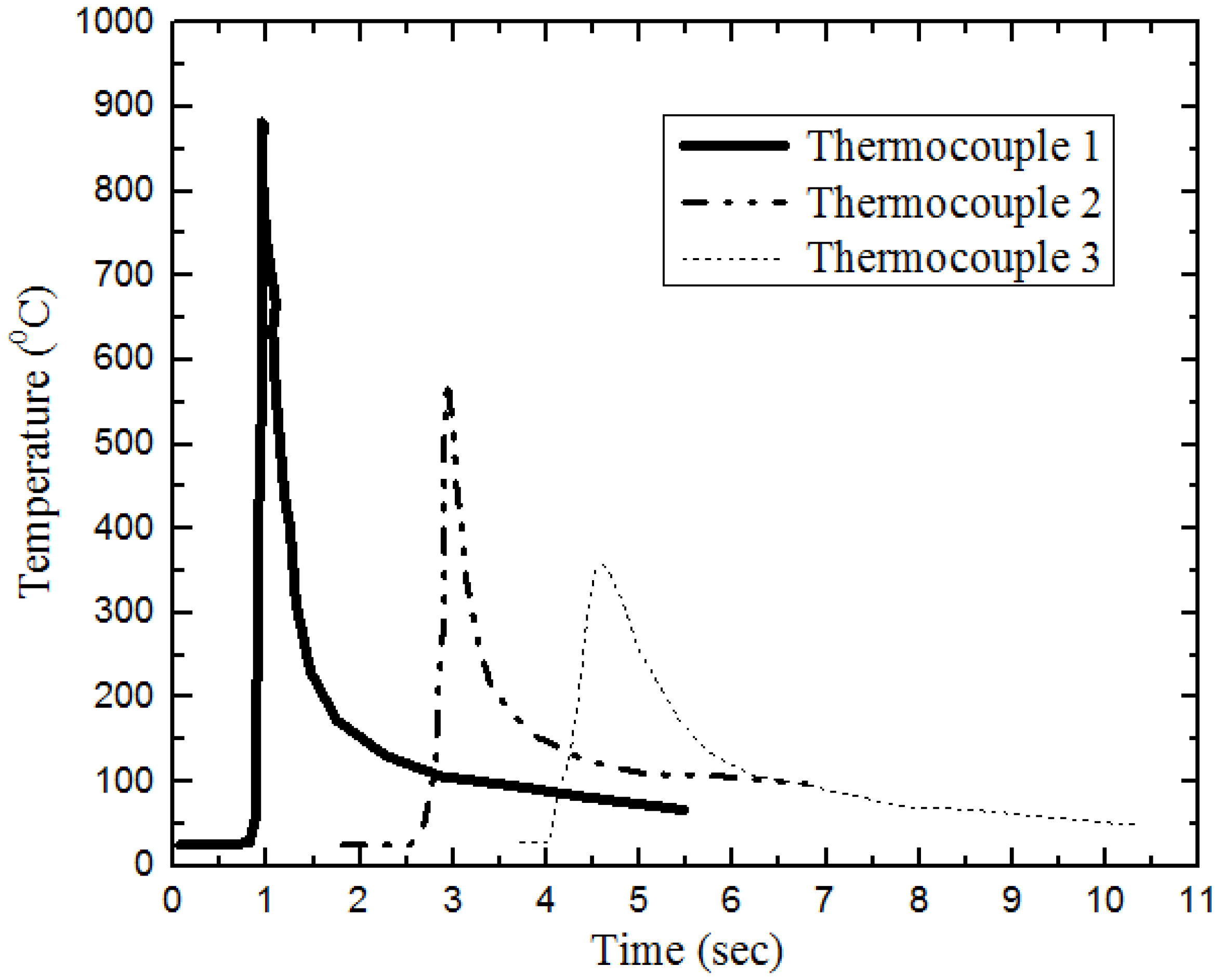
2.3. Thermocouple

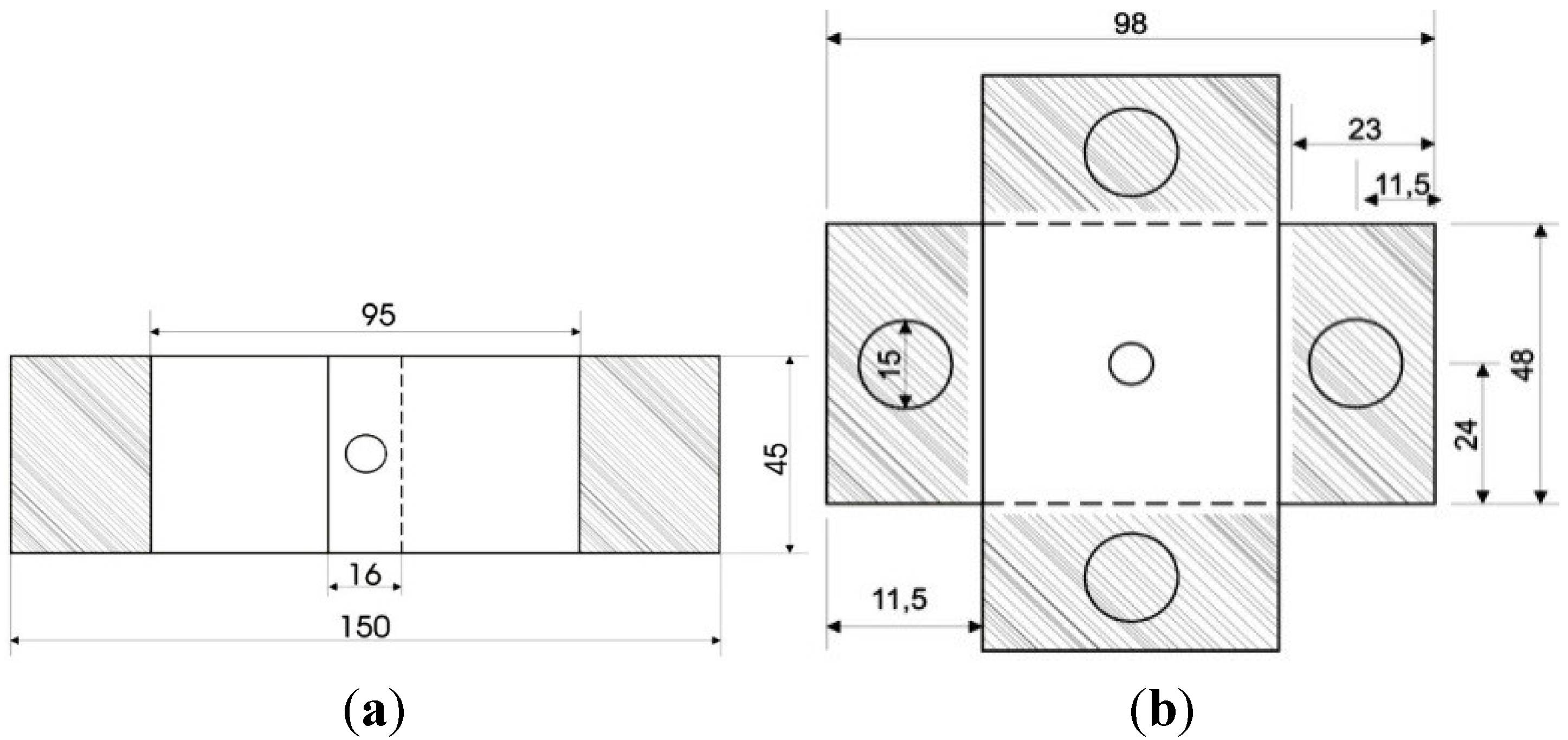
2.4. Tensile Tests and Specimen Analysis
3. Experimental Results and Discussion
3.1. Microstructure


3.2. Mechanical Properties

4. Summary and Conclusions
- Characterization and mechanical properties of the welded joints was performed. Light optical and electron microscopy, hardness mapping, and tensile testing were used for this purpose.
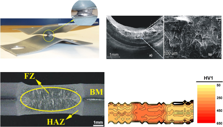
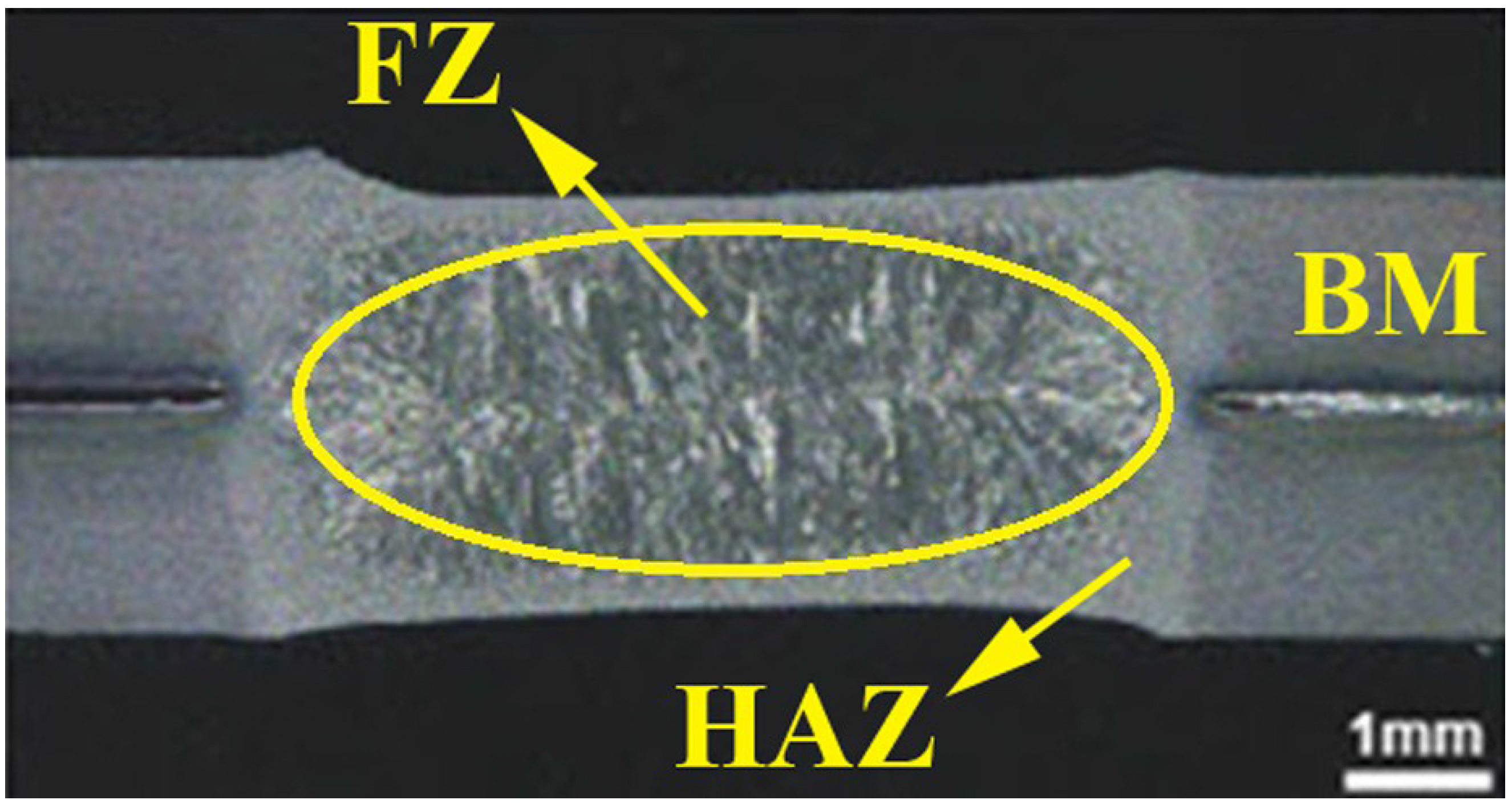
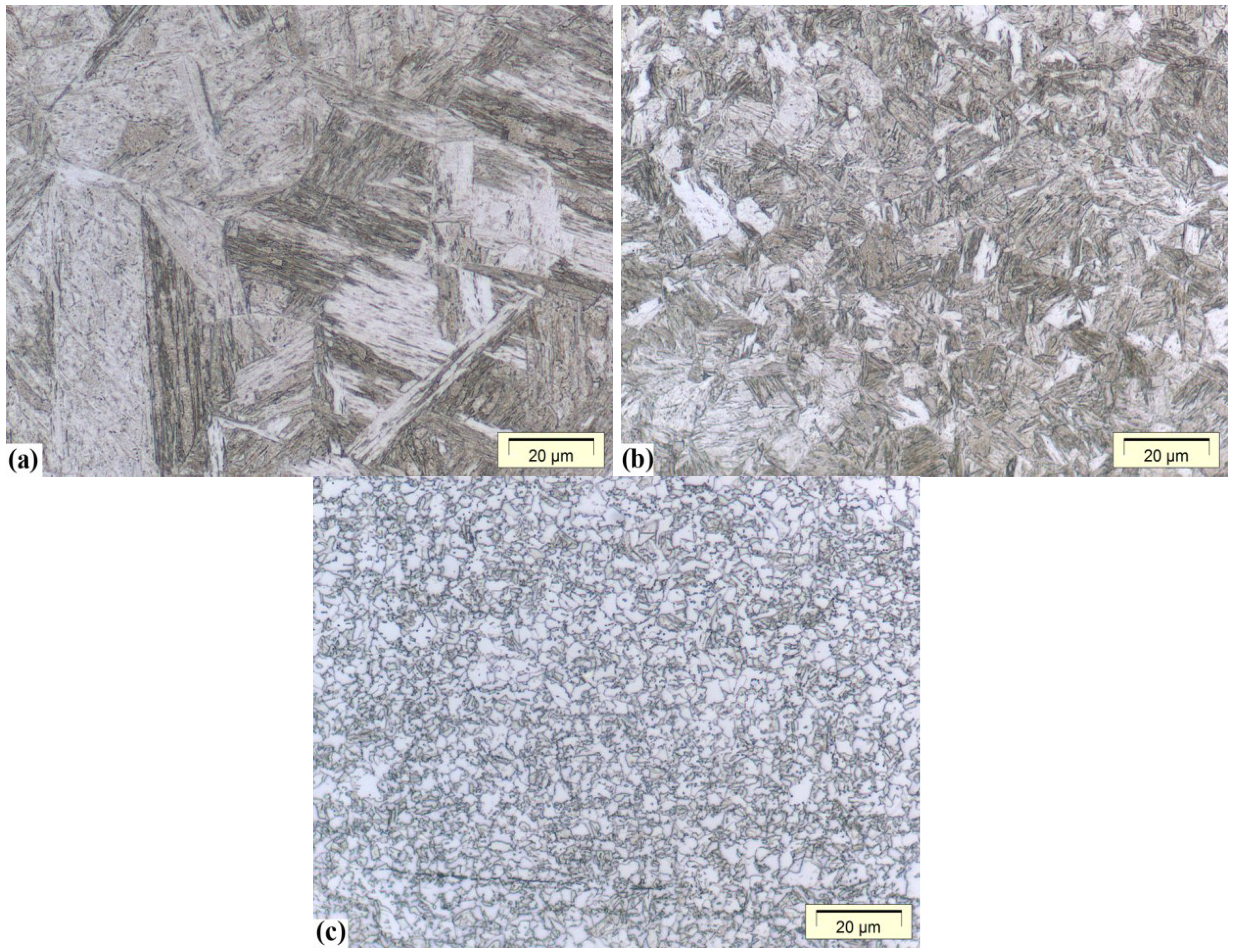
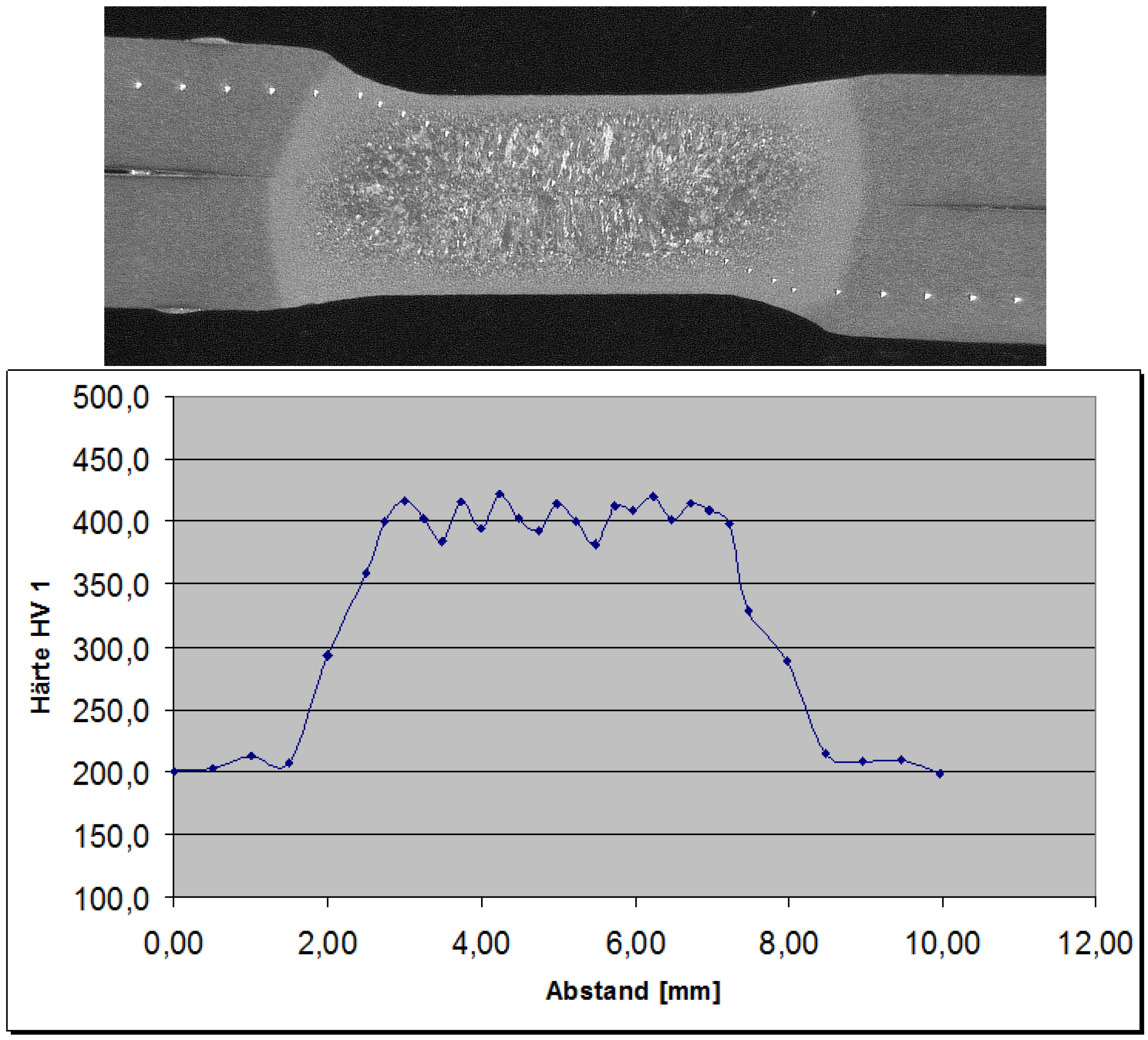
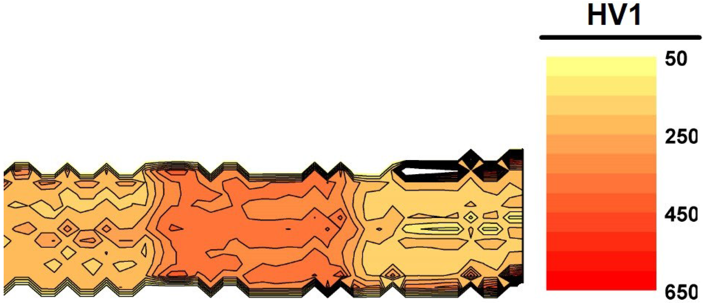
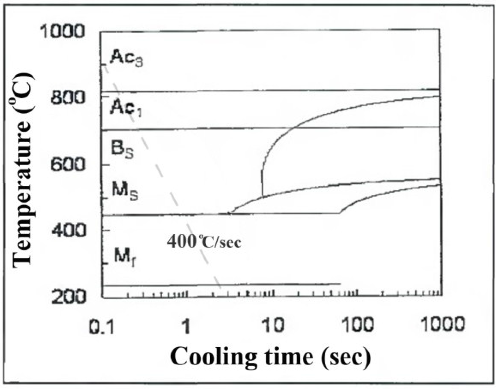
- The fusion zone in the RSW weld consisted of a hard martensitic columnar microstructure with hardness of about 400 HV.
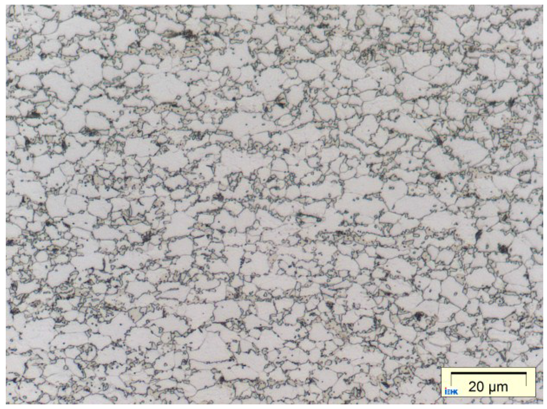
- HAZ consisted mainly of martensite, and other areas had a BM feature microstructure. Although, in microstructure of the BM zone near HAZ, the presence of some carbide phases distributed in ferrite matrix, as a result of tempering, was recognizable.
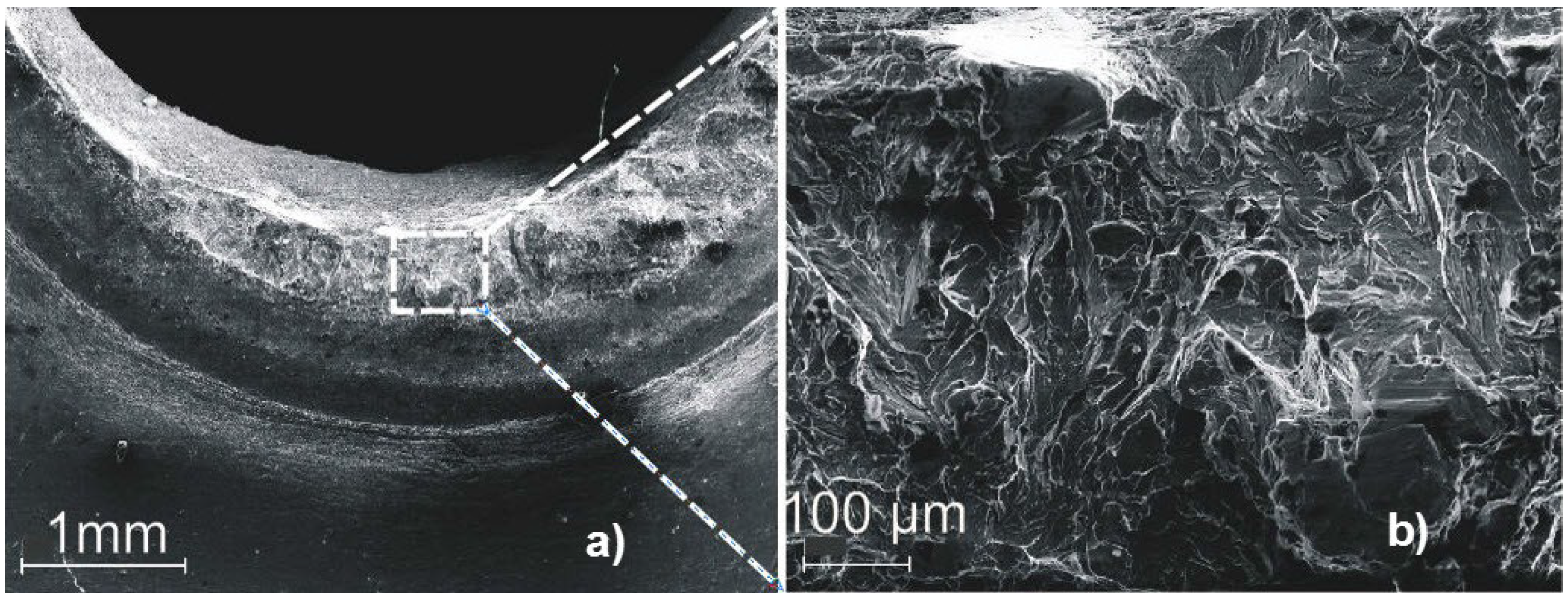
- Pull-out failure mode was the characteristic of fractured specimens, while the initial cracks were initiated from the periphery points around the weld region.
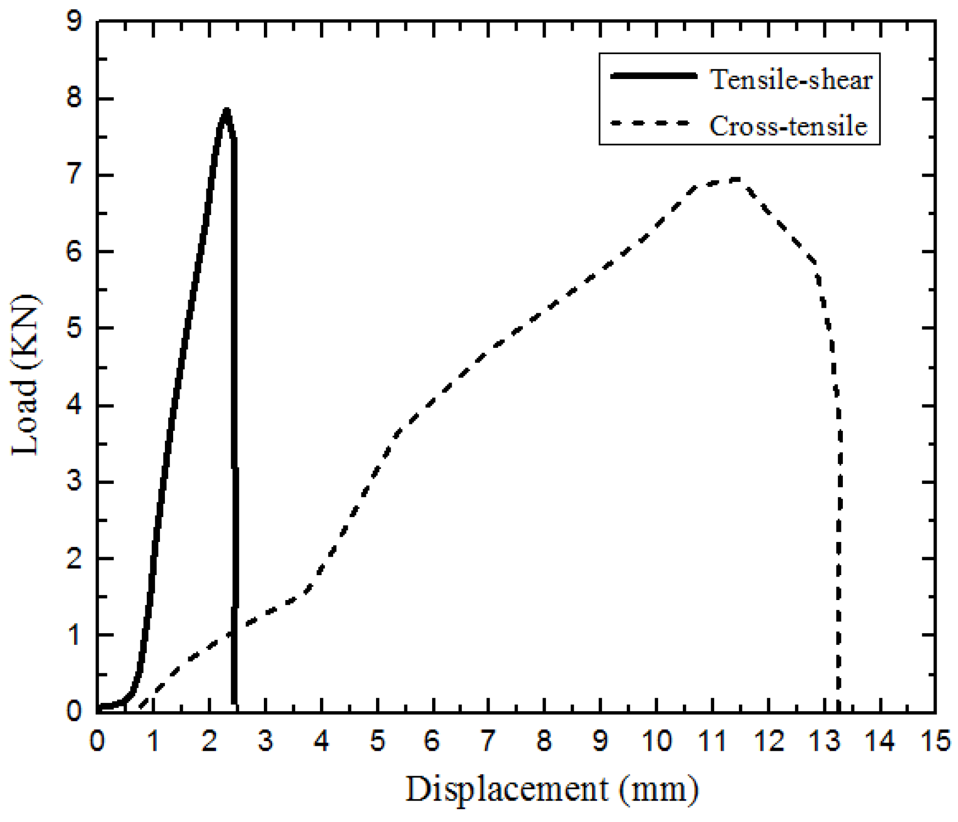
- Fracture surface analyses of the broken shear-tensile and cross-tensile specimens indicated a mainly brittle fracture surface; however, the presence of some deformation was observable in fracture surface.
Acknowledgments
Author Contributions
Conflicts of Interest
References
- Davies, G. Materials for Automobile Bodies; Elsevier: Butterworth–Heinemann, UK, 2003. [Google Scholar]
- Ramazani, A.; Mukherjee, K.; Prahl, U.; Bleck, W. Modelling the Effect of Microstructural Banding on the Flow Curve Behaviour of Dual-Phase (DP) Steels. Comput. Mater. Sci. 2012, 52, 46–54. [Google Scholar] [CrossRef]
- Ramazani, A.; Mukherjee, K.; Schwedt, A.; Goravanchi, P.; Prahl, U.; Bleck, W. Quantification of the Effect of Transformation-Induced Geometrically Necessary Dislocations on the Flow-Curve Modelling of Dual-Phase Steels. Int. J. Plasticity 2013, 43, 128–152. [Google Scholar] [CrossRef]
- Cornette, D.; Hourman, T.; Hudin, O.; Laurent, J.P.; Reynaert, A. High Strength Steels for Automotive Safety Parts. SAE Trans. J. Mater. Manuf. 2001, 110, 37–47. [Google Scholar]
- Ramazani, A.; Ebrahimi, Z.; Prahl, U. Study the effect of martensite banding on the failure initiation in dual-phase steel. Comput. Mater. Sci. 2014, 87, 241–247. [Google Scholar] [CrossRef]
- Shaw, J.R.; Zuidema, B.K. New High Strength Steels Help Automakers Reach Future Goals for Safety, Affordability, Fuel Efficiency and Environmental Responsibility. SAE Trans. J. Mater. Manuf. 2001, 110, 976–983. [Google Scholar]
- Mukherjee, K.; Ramazani, A.; Yang, L.; Prahl, U.; Bleck, W.; Reisen, U. Characterization of gas metal arc welded hot rolled DP600 steel. Steel Res. Int. 2011, 82, 1408–1416. [Google Scholar] [CrossRef]
- Ramazani, A.; Bruehl, S.; Gerber, T.; Bleck, W.; Prahl, U. Quantification of bake hardening effect in DP600 and TRIP700 steels. Mater. Des. 2014, 57, 479–486. [Google Scholar] [CrossRef]
- Wang, W.; Li, M.; He, C.; Wei, X.; Wang, D.; Du, H. Experimental Study on High Strain Rate Behavior of High Strength 600–1000 MPa Dual Phase Steels and 1200 MPa Fully Martensitic Steels. Mater. Des. 2013, 47, 510–521. [Google Scholar] [CrossRef]
- Abbasi, M.; Ketabchi, M.; Ramazani, A.; Abbasi, M.; Prahl, U. Investigation into the effects of weld zone and geometric discontinuity on the formability reduction of tailor welded blanks. Comput. Mater. Sci. 2012, 59, 158–164. [Google Scholar] [CrossRef]
- Ramazani, A.; Mukherjee, K.; Prahl, U.; Bleck, W. Transformation-Induced, Geometrically Necessary, Dislocation-Based Flow Curve Modeling of Dual-Phase Steels: Effect of Grain Size. Metall. Mater. Trans. A 2012, 43, 3850–3869. [Google Scholar] [CrossRef]
- Ramazani, A.; Mukherjee, K.; Quade, H.; Prahl, U.; Bleck, W. Correlation between 2D and 3D flow curve modelling of DP steels using a microstructure-based RVE approach. Mater. Sci. Eng. A 2013, 560, 129–139. [Google Scholar] [CrossRef]
- Ramazani, A.; Schwedt, A.; Aretz, A.; Prahl, U. Failure Initiation in Dual-Phase Steel. Key Eng. Mater. 2014, 586, 67–71. [Google Scholar] [CrossRef]
- Ramazani, A.; Mukherjee, K.; Abdurakhmanov, A.; Prahl, U.; Schleser, M.; Reisgen, U.; Bleck, W. Micro-Macro Characterisation and Modelling of Mechanical Properties of Gas Metal Arc Welded (GMAW) DP600 Steel. Mater. Sci. Eng. A 2014, 589, 1–14. [Google Scholar] [CrossRef]
- Reisgen, U.; Harms, A.; Ohse, P.; Schiebahn, A. Fracture Behaviour of Resistance Spot Welds on High-Strength and Higher-Strength Steels. Weld. Cut. 2009, 8, 148–151. [Google Scholar]
- Ramazani, A.; Li, Y.; Mukherjee, K.; Prahl, U.; Bleck, W.; Abdurakhmanov, A.; Schleser, M.; Reisgen, U. Microstructure evolution simulation in hot rolled DP600 steel during gas metal arc welding. Comput. Mater. Sci. 2013, 68, 107–116. [Google Scholar] [CrossRef]
- Zhao, D.; Wang, Y.; Zhang, L.; Zhang, P. Effects of Electrode Force on Microstructure and Mechanical Behavior of the Resistance Spot Welded DP600 Joint. Mater. Des. 2013, 50, 72–77. [Google Scholar] [CrossRef]
- Shi, G.; Westgate, S.A. Resistance Spot Welding of High Strength Steels. Int. J. Join. Mater. 2004, 16, 9–14. [Google Scholar]
- Zhang, H.; Wei, A.; Qiu, X.; Chen, J. Microstructure and Mechanical Properties of Resistance Spot Welded Dissimilar Thickness DP780/DP600 Dual-Phase Steel Joints. Mater. Des. 2014, 54, 443–449. [Google Scholar] [CrossRef]
- Ma, C.; Chen, D.L.; Bhole, S.D.; Boudreau, G.; Lee, A.; Biro, E. Microstructure and Fracture Characteristics of Spot-Welded DP600 Steel. Mater. Sci. Eng. A 2008, 485, 334–346. [Google Scholar] [CrossRef]
- Zhang, H.; Senkara, J. Resistance Welding: Fundamentals and Applications; Taylor and Francis CRC Press: Boca Raton, FL, USA, 2006. [Google Scholar]
- Sun, X.; Stephens, E.V.; Khaleel, M.A. Effects of Fusion Zone Size and Failure Mode on Peak Load and Energy Absorption of Advanced High-Strength Steel Spot Welds. Weld. J. 2007, 86, 18s–25s. [Google Scholar]
- Pouranvari, M.; Marashi, S.P.H. Failure Mode Transition in AHSS Resistance Spot Welds. Part I. Controlling Factors. Mater. Sci. Eng. A 2011, 528, 8337–8343. [Google Scholar] [CrossRef]
- Khan, M.I.; Kuntz, M.L.; Biro, E.; Zhou, Y. Microstructure and Mechanical Properties of Resistance Spot Welded Advanced High Strength Steels. Mater. Trans. 2008, 49, 1629–1637. [Google Scholar] [CrossRef]
- Hayat, F.; Ibrahim, S. The Effect of Welding Parameters on Fracture Toughness of Resistance Spot-Welded Galvanized DP600 Automotive Steel Sheets. Int. J. Adv. Manuf. Tech. 2011, 58, 1043–1050. [Google Scholar] [CrossRef]
- Hernandez, V.H.B.; Kuntz, M.L.; Khan, M.I. Influence of Microstructure and Weld Size on the Mechanical Behaviour of Dissimilar AHSS Resistance Spot Welds. Sci. Tech. Weld. Join. 2008, 13, 769–776. [Google Scholar] [CrossRef]
- Zhong, N.; Liao, X.; Wang, M.; Wu, Y.; Rong, Y. Improvement of microstructures and mechanical properites of resistance spot welded DP600 steel by double pulse technology. Mater. Trans. 2011, 52, 2143–2150. [Google Scholar] [CrossRef]
- Gould, J.; Khurana, S.; Li, T. Predictions of Microstructures When Welding Automotive Advanced High-Strength Steels. Weld. J. 2006, 85, 111s–116s. [Google Scholar]
- Bleck, W. Materials Sciecne of Steel; Verlag Mainz: Aachen, Germany, 2007. [Google Scholar]
- Naderi, M.; Ketabchi, M.; Abbasi, M.; Bleck, W. Analysis of microstructure and mechanical properties of different high strength carbon steels after hot stamping. J. Mater. Process. Tech. 2011, 211, 1117–1125. [Google Scholar] [CrossRef]
- Naderi, M.; Abbasi, M.; Akbari, A.S. Enhanced mechanical properties of a hot-stamped advanced high-strength steel via tempering treatment. Metall. Mater. Trans. A 2013, 44, 1852–1861. [Google Scholar] [CrossRef]
- Kalaki, A.; Ketabchi, M.; Abbasi, M. Thixo-joining of D2 and M2 tool steels: analysis of microstructure and mechanical properties. Int. J. Mater. Res. 2014, 105, 764–769. [Google Scholar] [CrossRef]
- Ramazani, A.; Pinard, P.T.; Richter, S.; Schwedt, A.; Prahl, U. Characterisation of Microstructure and Modelling of Flow Behaviour of Bainite-Aided Dual-Phase Steel. Comput. Mater. Sci. 2013, 80, 134–141. [Google Scholar] [CrossRef]
- Abbasi, M.; Naderi, M.; Akbari, A.S. Isothermal versus non-isothermal hot compression process: A comparative study on phase transformation and structure-property relationships. Mater. Des. 2013, 45, 1–5. [Google Scholar] [CrossRef]
© 2015 by the authors; licensee MDPI, Basel, Switzerland. This article is an open access article distributed under the terms and conditions of the Creative Commons Attribution license (http://creativecommons.org/licenses/by/4.0/).
Share and Cite
Ramazani, A.; Mukherjee, K.; Abdurakhmanov, A.; Abbasi, M.; Prahl, U. Characterization of Microstructure and Mechanical Properties of Resistance Spot Welded DP600 Steel. Metals 2015, 5, 1704-1716. https://doi.org/10.3390/met5031704
Ramazani A, Mukherjee K, Abdurakhmanov A, Abbasi M, Prahl U. Characterization of Microstructure and Mechanical Properties of Resistance Spot Welded DP600 Steel. Metals. 2015; 5(3):1704-1716. https://doi.org/10.3390/met5031704
Chicago/Turabian StyleRamazani, Ali, Krishnendu Mukherjee, Aydemir Abdurakhmanov, Mahmoud Abbasi, and Ulrich Prahl. 2015. "Characterization of Microstructure and Mechanical Properties of Resistance Spot Welded DP600 Steel" Metals 5, no. 3: 1704-1716. https://doi.org/10.3390/met5031704