
Mechanical Properties Analysis of an Al-Mg Alloy Connecting Rod with Submicrometric Structure

 ,
,
Abstract
:1. Introduction
2. Experimental Section
2.1. Manufacturing of the Connecting Rods
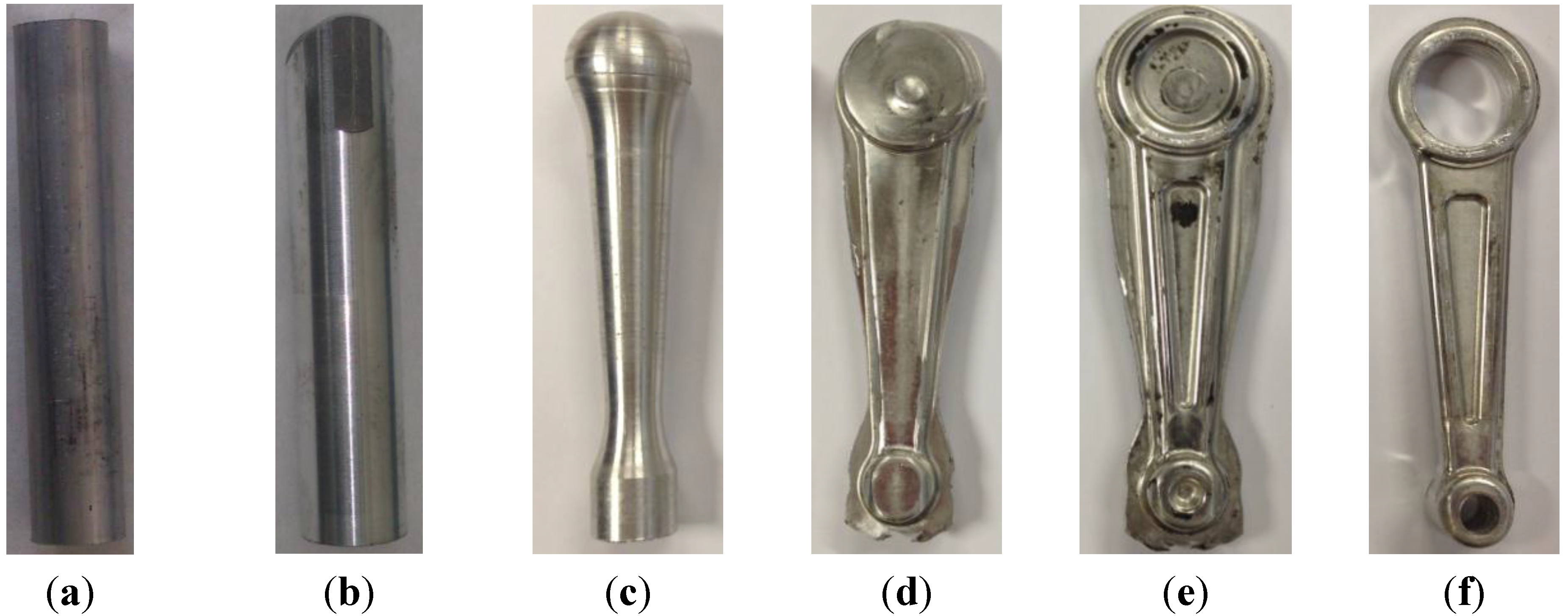
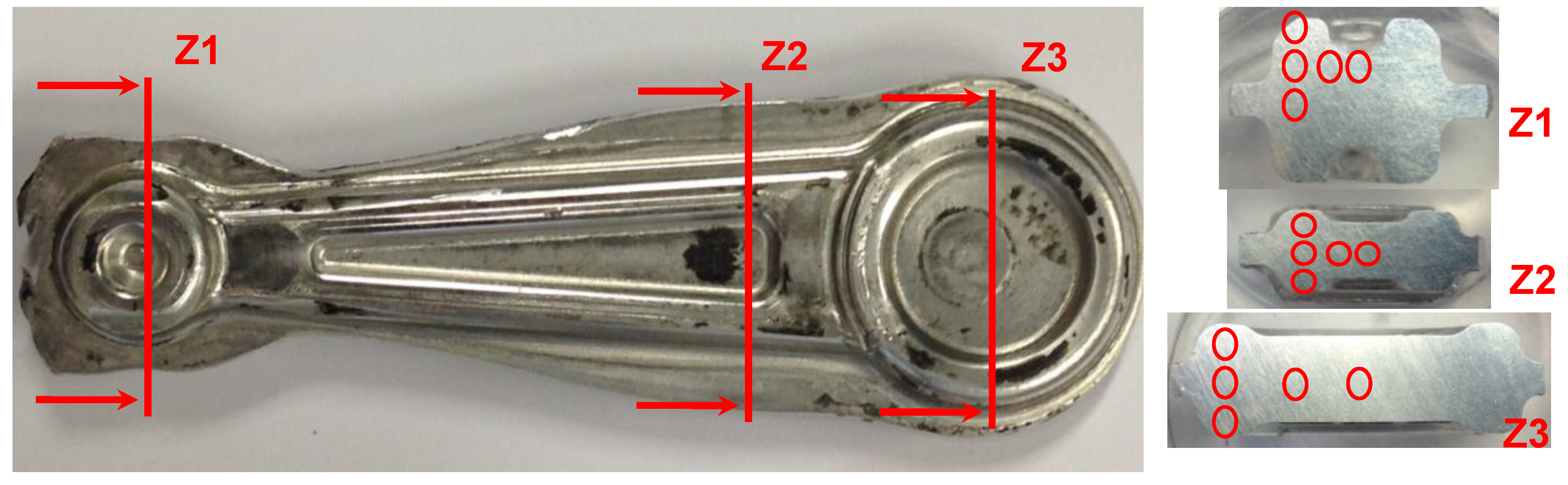
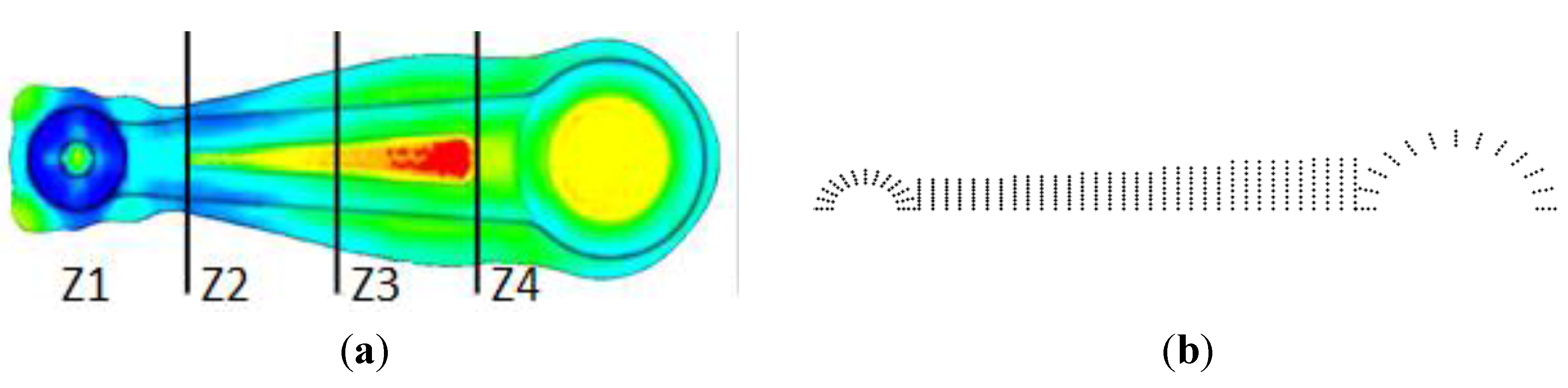
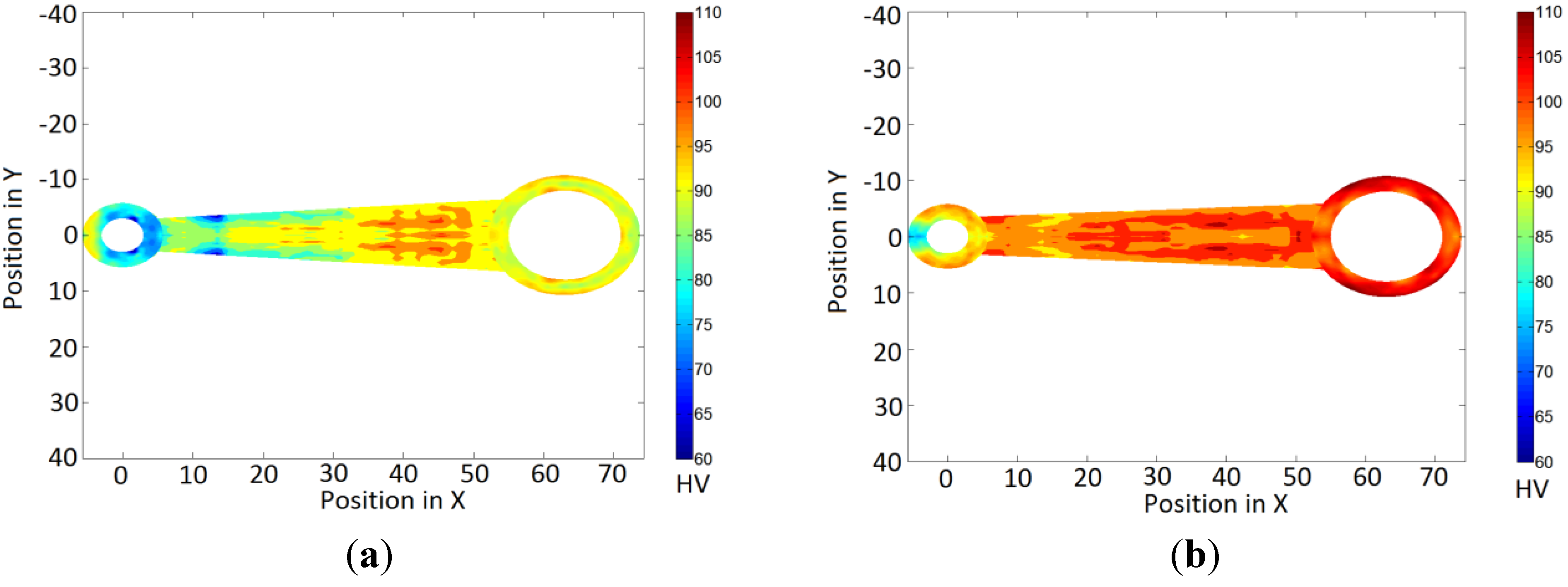
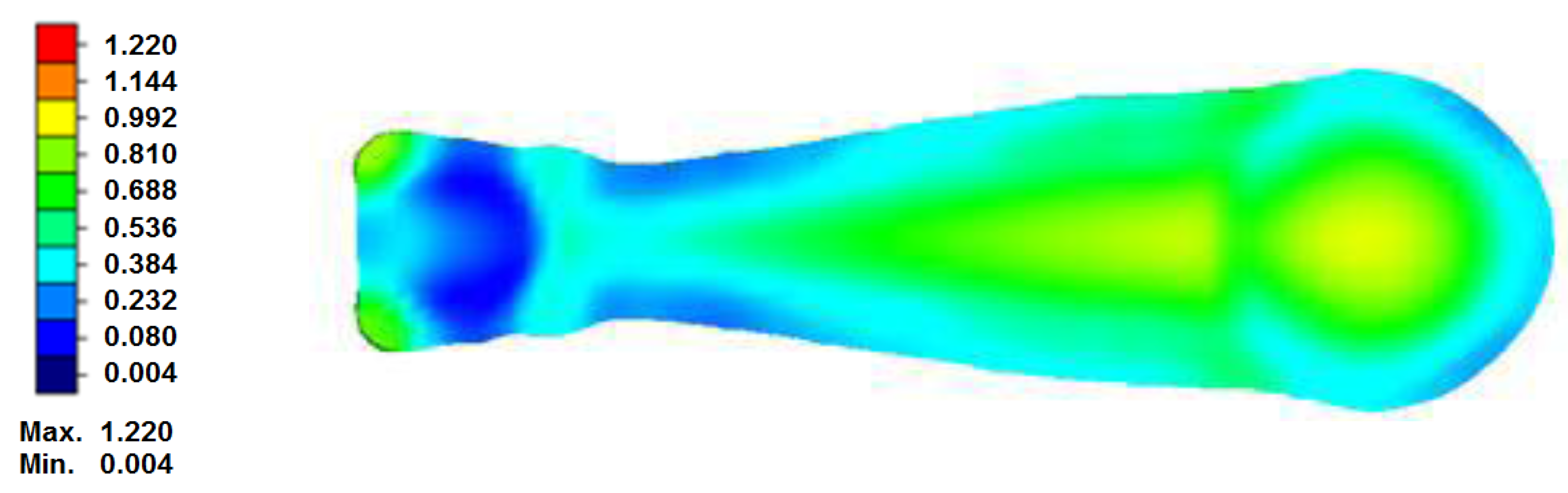
2.2. Design of the Forging Study at Different Temperature Values


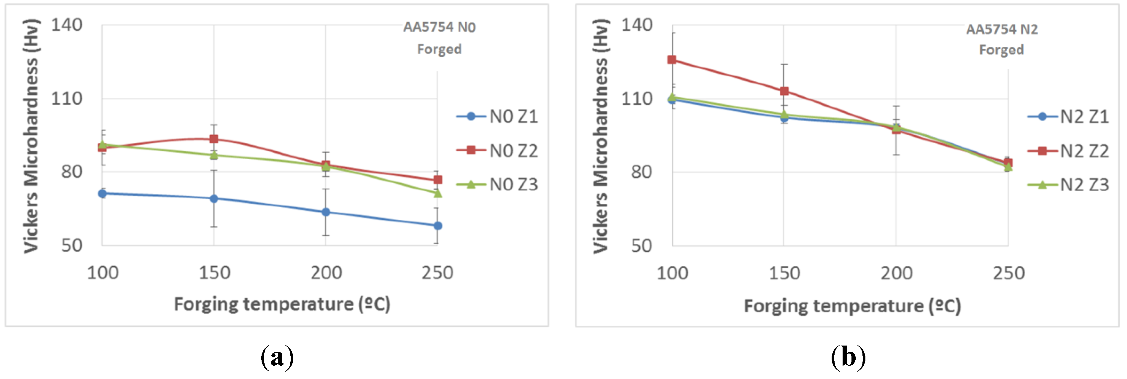
| Temperature | 100 °C | 150 °C | 200 °C | 250 °C | ||||||||
|---|---|---|---|---|---|---|---|---|---|---|---|---|
| Zone | Z1 | Z2 | Z3 | Z1 | Z2 | Z3 | Z1 | Z2 | Z3 | Z1 | Z2 | Z3 |
| Hv1 | 69.5 | 82.5 | 91.1 | 68.8 | 92.9 | 85.7 | 62.7 | 78.7 | 82.0 | 50.6 | 77.9 | 71.6 |
| Hv2 | 73.3 | 85.3 | 86.6 | 69.1 | 86.9 | 87.5 | 51.6 | 79.6 | 83.2 | - | 70.8 | 72.9 |
| Hv3 | 72.7 | 86.1 | 88.4 | 80.2 | 88.3 | 84.7 | 73.4 | 80.1 | 82.3 | 64.7 | 75.6 | 68.4 |
| Hv4 | 72.2 | 96 | 96.5 | 74.7 | 98.9 | 89.0 | 72.9 | 86.9 | 79.2 | 59.1 | 77.4 | 71.3 |
| Hv5 | 68.6 | 98.9 | 93.5 | 72.5 | 99.7 | 87.5 | 57.8 | 89.6 | 84.1 | - | 81.1 | 72.5 |
| Mean | 71.3 | 89.8 | 91.2 | 69.2 | 93.3 | 86.9 | 63.7 | 83.0 | 82.2 | 58.1 | 76.6 | 71.3 |
| Standard Deviation | 2.1 | 7.2 | 3.9 | 11.6 | 5.9 | 1.7 | 9.5 | 4.9 | 1.8 | 7.1 | 3.8 | 1.8 |
| Temperature | 100 °C | 150 °C | 200 °C | 250 °C | ||||||||
|---|---|---|---|---|---|---|---|---|---|---|---|---|
| Zone | Z1 | Z2 | Z3 | Z1 | Z2 | Z3 | Z1 | Z2 | Z3 | Z1 | Z2 | Z3 |
| Hv1 | 109.2 | 110.4 | 104.5 | 101.8 | 106.2 | 97.7 | 96.3 | 91.9 | 99.7 | 83.4 | 82.9 | 80.5 |
| Hv2 | 111.7 | 123.9 | 108.6 | 102.5 | 106.6 | 102.2 | 96.4 | 94.6 | 94.9 | 84.6 | 81.0 | 82.4 |
| Hv3 | 106.9 | 119.5 | 109.4 | 103.4 | 110.7 | 105.2 | 97.9 | 85.0 | 95.6 | 86.9 | 85.0 | 80.8 |
| Hv4 | 109.5 | 134.1 | 117.4 | 103.2 | 109.9 | 106.1 | 99.8 | 104.0 | 100.2 | 83.0 | 84.3 | 85.3 |
| Hv5 | 110.8 | 124.1 | 113.8 | 100.7 | 132.0 | 106.6 | 99.5 | 109.8 | 101.4 | 79.6 | 85.8 | 82.0 |
| Mean | 109.6 | 125.7 | 110.7 | 102.3 | 113.1 | 103.6 | 98.0 | 97.1 | 98.4 | 83.5 | 83.8 | 82.2 |
| Standard Deviation | 1.8 | 11.2 | 5.0 | 1.1 | 10.8 | 3.7 | 1.7 | 9.9 | 2.9 | 2.7 | 1.9 | 1.9 |

| Temperature | 240 °C | 260 °C | 280 °C | 300 °C | 320 °C |
|---|---|---|---|---|---|
| Hv1 | 100.6 | 98.4 | 96.7 | 89.6 | 63.8 |
| Hv2 | 100.1 | 98.5 | 99.5 | 89.7 | 64.8 |
| Hv3 | 97.6 | 98.2 | 97.5 | 92.5 | 63.6 |
| Hv4 | 98.6 | 98.1 | 96.6 | 91.7 | 66.6 |
| Hv5 | 97.2 | 97.9 | 97.2 | 89.8 | 64.0 |
| Mean | 98.8 | 98.2 | 97.5 | 90.7 | 64.6 |
| Standard Deviation | 1.5 | 0.2 | 1.2 | 1.3 | 1.2 |


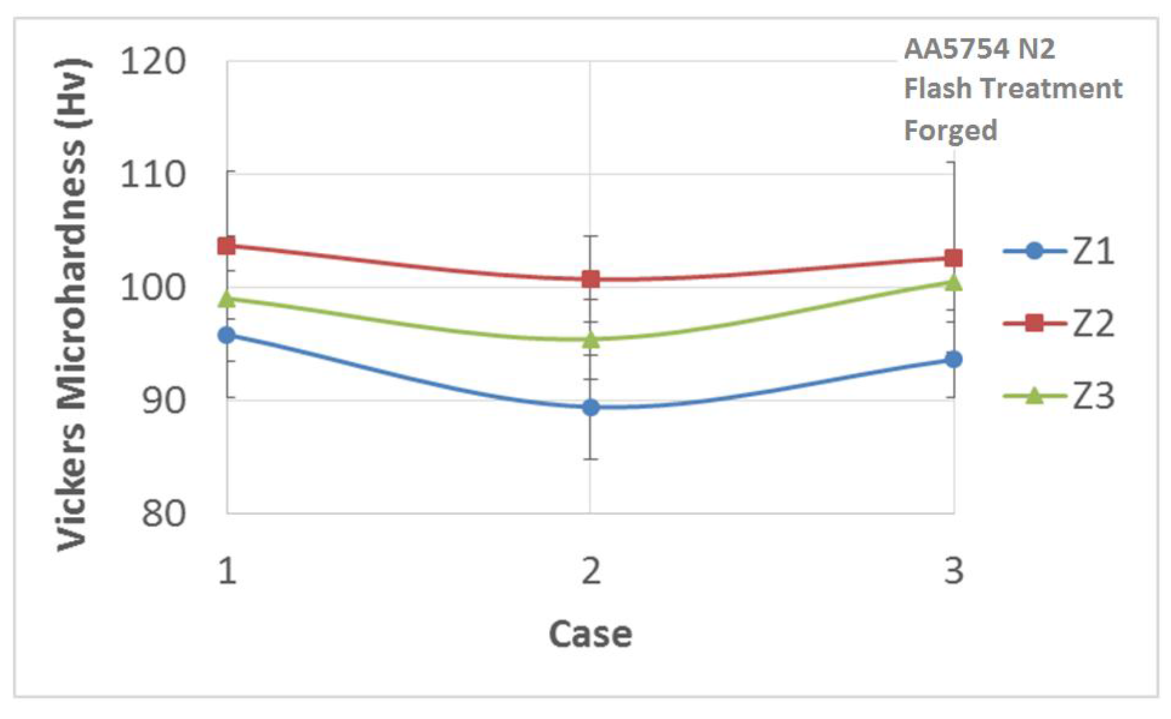
| Temperature | Case 1 | Case 2 | Case 3 | ||||||
|---|---|---|---|---|---|---|---|---|---|
| 280 °C → 150 °C | 300 °C → 100 °C | 300 °C → 150 °C | |||||||
| Zone | Z1 | Z2 | Z3 | Z1 | Z2 | Z3 | Z1 | Z2 | Z3 |
| Hv1 | 96.3 | 103.0 | 96.6 | 90.1 | 100.8 | 94.4 | 93.0 | 100.6 | 97.6 |
| Hv2 | 86.7 | 97.0 | 91.9 | 81.4 | 98.9 | 90.0 | 88.1 | 96.1 | 99.0 |
| Hv3 | 95.4 | 98.5 | 97.1 | 90.8 | 96.4 | 95.6 | 94.6 | 93.9 | 101.4 |
| Hv4 | 99.2 | 107.1 | 104.6 | 91.9 | 106.6 | 98.1 | 95.5 | 109.0 | 100.3 |
| Hv5 | 101.3 | 112.9 | 104.6 | 92.7 | 101.0 | 98.7 | 96.7 | 113.5 | 104.2 |
| Mean | 95.8 | 103.7 | 99.0 | 89.4 | 100.7 | 95.4 | 93.6 | 102.6 | 100.5 |
| Standard Deviation | 5.6 | 6.5 | 5.5 | 4.6 | 3.8 | 3.5 | 3.3 | 8.4 | 2.5 |

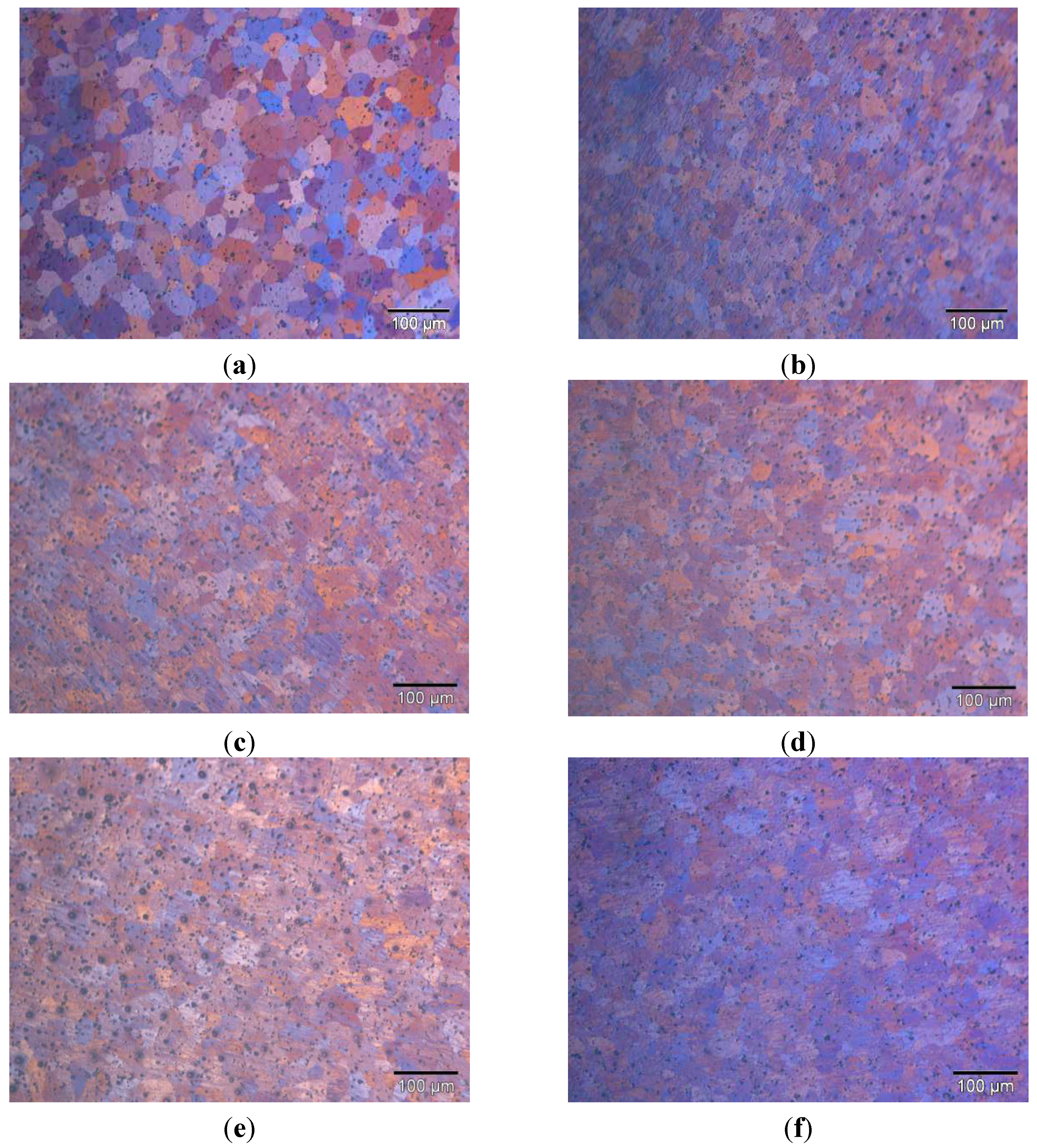
3. Results and Discussion


4. Conclusions
Acknowledgments
Author Contributions
Conflicts of Interest
References
- Valiev, R.Z.; Islamgaliev, R.K.; Alexandrov, I.V. Bulk nanostructured materials from severe plastic deformation. Prog. Mater. Sci. 2000, 45, 103–189. [Google Scholar] [CrossRef]
- Valiev, R.Z.; Langdon, T.G. Principles of equal-channel angular pressing as a processing tool for grain refinement. Prog. Mater. Sci. 2006, 51, 881–981. [Google Scholar] [CrossRef]
- Zhu, Y.T.; Lowe, T.C.; Langdon, T.G. Performance and applications of nanostructured materials produced by severe plastic deformation. Scr. Mater. 2004, 51, 825–830. [Google Scholar] [CrossRef]
- Sakai, G.; Horita, Z.; Langdon, T.G. Grain refinement and superplasticity in an aluminum alloy processed by high-pressure torsion. Mater. Sci. Eng. A 2005, 393, 344–351. [Google Scholar] [CrossRef]
- Nickel, D.; Dietrich, D.; Mehner, T.; Frint, P.; Spieler, D.; Lampke, T. Effect of strain localization on pitting corrosion of an AlMgSi0.5 alloy. Metals 2015, 5, 172–191. [Google Scholar] [CrossRef]
- Segal, V.M. Equal channel angular extrusion: from macromechanics to structure formation. Mater. Sci. Eng. A 1999, 271, 322–333. [Google Scholar] [CrossRef]
- Luis, C.J. On the correct selection of the channel die in ECAP processes. Scr. Mater. 2004, 50, 387–393. [Google Scholar] [CrossRef]
- Kim, W.J.; Sa, Y.K.; Kim, H.K.; Yoon, U.S. Plastic forming of the equal-channel angular pressing processed 6061 aluminum alloy. Mater. Sci. Eng. A 2008, 487, 360–368. [Google Scholar] [CrossRef]
- Humphreys, F.J.; Hatherly, M. Recrystallization and Related Annealing Phenomena, 2nd ed.; Elsevier: Amsterdam, The Netherland, 2004. [Google Scholar]
- Ferrasse, S.; Segal, V.M.; Alford, F.; Kardokus, J.; Strothers, S. Scale up and application of equal-channel angular extrusion for the electronics and aerospace industries. Mater. Sci. Eng. A 2008, 493, 130–140. [Google Scholar] [CrossRef]
- Altan, T.; Ngaile, G.; Shen, G. Cold And Hot Forging: Fundamentals And Applications, 1st ed.; ASM International: Materials Park, OH, USA, 2005. [Google Scholar]
- Poortman, S.; Duchêne, L.; Habraken, A.M.; Verlinden, B. Modelling compression tests on aluminium produced by equal channel angular extrusion. Acta Mater. 2009, 57, 1821–1830. [Google Scholar] [CrossRef]
- Agena, A.S.M. A study of flow characteristics of nanostructured Al-6082 alloy produced by ECAP under upsetting test. J. Mater. Process. Technol. 2009, 209, 856–863. [Google Scholar] [CrossRef]
- Luis, C.J.; Puertas, I.; Salcedo, D.; León, J.; Pérez, I. Comparison between FEM and Experimental Results in the Upsetting of Nano-Structured Materials. Mater. Sci. Forum 2012, 713, 31–36. [Google Scholar] [CrossRef]
- Lee, J.H.; Kang, S.H.; Yang, D.Y. Novel forging technology of a magnesium alloy impeller with twisted blades of micro-thickness. CIRP Ann. Manuf. Technol. 2008, 57, 261–264. [Google Scholar] [CrossRef]
- Yanagida, A.; Joko, K.; Azushima, A. Formability of steels subjected to cold ECAE process. J. Mater. Process. Technol. 2008, 201, 390–394. [Google Scholar] [CrossRef]
- Choi, J.S.; Nawaz, S.; Hwang, S.K.; Lee, H.C.; Im, Y.T. Forgeability of ultra-fine grained aluminum alloy for bolt forming. Int. J. Mech. Sci. 2010, 52, 1269–1276. [Google Scholar] [CrossRef]
- Luis, C.J.; Salcedo, D.; León, J.; Puertas, I.; Fuertes, J.P.; Luri, R. Manufacturing of nanostructured rings from previously ECAE-processed AA5083 alloy by isothermal forging. J. Nanomater. 2013, 2013, 1–14. [Google Scholar] [CrossRef]
- Puertas, I.; Luis Pérez, C.J.; Salcedo, D.; León, J.; Fuertes, J.P.; Luri, R. Design and mechanical property analysis of AA1050 turbine blades manufactured by equal channel angular extrusion and isothermal forging. Mater. Des. 2013, 52, 774–784. [Google Scholar] [CrossRef]
- Luis Pérez, C.J.; Salcedo, D.; Puertas, I. Design and mechanical property analysis of ultrafine grained gears from AA5083 previously processed by equal channel angular pressing and isothermal forging. Mater. Des. 2014, 63, 126–135. [Google Scholar] [CrossRef]
- Vazquez, V.; Altan, T. Die design for flashless forging of complex parts. J. Mater. Process. Tech. 2000, 98, 81–89. [Google Scholar] [CrossRef]
- Grass, H.; Krempaszky, C.; Werner, E. 3-D FEM-simulation of hot forming processes for the production of a connecting rod. Comput. Mater. Sci. 2006, 36, 480–489. [Google Scholar] [CrossRef]
- Lee, M.K.; Lee, H.; Lee, T.S.; Jang, H. Buckling sensitivity of a connecting rod to the shank sectional area reduction. Mater. Des. 2010, 31, 2796–2803. [Google Scholar] [CrossRef]
- Shenoy, P.S.; Fatemi, A. Connecting Rod Optimization for Weight and Cost Reduction; SAE Technical Paper 2005-01-0987; SAE International: Warrendale, PA, USA, 2005. [Google Scholar] [CrossRef]
- Lewis, R. Friction in a hydraulic motor piston/cam roller contact lined with PTFE impregnated cloth. Wear 2009, 266, 888–892. [Google Scholar] [CrossRef]
- Khare, S.; Singh, O.P.; Dora, K.B.; Sasun, C. Spalling investigation of connecting rod. Eng. Fail. Anal. 2012, 19, 77–86. [Google Scholar] [CrossRef]
- Fuertes, J.P.; León, J.; Luis, C.J.; Salcedo, D.; Puertas, I.; Luri, R. Design, optimization and mechanical property analysis of a submicrometric aluminium alloy connecting rod. J. Nanomater. major revision required.
- Fuertes, J.P.; Murillo, O.; León, J.; Luis, C.; Salcedo, D.; Puertas, I.; Luri, R. Mechanical properties analysis of an Al-Mg alloy connecting rod with submicrometric structure. MESIC 2015. accepted. [Google Scholar]
© 2015 by the authors; licensee MDPI, Basel, Switzerland. This article is an open access article distributed under the terms and conditions of the Creative Commons Attribution license (http://creativecommons.org/licenses/by/4.0/).
Share and Cite
León, J.; Salcedo, D.; Murillo, Ó.; Luis, C.J.; Fuertes, J.P.; Puertas, I.; Luri, R. Mechanical Properties Analysis of an Al-Mg Alloy Connecting Rod with Submicrometric Structure. Metals 2015, 5, 1397-1413. https://doi.org/10.3390/met5031397
León J, Salcedo D, Murillo Ó, Luis CJ, Fuertes JP, Puertas I, Luri R. Mechanical Properties Analysis of an Al-Mg Alloy Connecting Rod with Submicrometric Structure. Metals. 2015; 5(3):1397-1413. https://doi.org/10.3390/met5031397
Chicago/Turabian StyleLeón, Javier, Daniel Salcedo, Óscar Murillo, Carmelo J. Luis, Juan P. Fuertes, Ignacio Puertas, and Rodrigo Luri. 2015. "Mechanical Properties Analysis of an Al-Mg Alloy Connecting Rod with Submicrometric Structure" Metals 5, no. 3: 1397-1413. https://doi.org/10.3390/met5031397