
Effect of Sphere Properties on Microstructure and Mechanical Performance of Cast Composite Metal Foams


Abstract
:1. Introduction
2. Materials, Processing, and Experimental Procedure
2.1. Materials and Processing

| Component | Fe | C | Mn | Si | Cr | Ni | Mo | Al | Mg | Cu | Ti | Zn |
|---|---|---|---|---|---|---|---|---|---|---|---|---|
| 3.7 mm Sphere | Balance | 0.03 | 0.20 | 0.90 | 17.00 | 13.00 | 2.20 | 0 | 0 | 0 | 0 | 0 |
| 4.0 mm Sphere | Balance | 0.64 | 0.11 | 0.73 | 16.91 | 12.35 | 2.20 | 0 | 0 | 0 | 0 | 0 |
| Al Matrix | 0.5 | 0 | 0.28 | 7.01 | 0.02 | 0 | 0 | Balance | 0.39 | 0.11 | 0.09 | 0.06 |
2.2. Sample Preparation
2.3. Microstructural Characterization
2.4. Density Calculation
2.5. Mechanical Testing
3. Results
3.1. Structural Properties


| Sphere Diameter (mm) | Roughness (µm) |
|---|---|
| 3.7 | 3.897 |
| 2.944 | |
| 8.418 | |
| 2.971 | |
| Average | 4.558 |
| 4.0 | 6.561 |
| 5.831 | |
| 5.144 | |
| 5.329 | |
| Average | 5.716 |


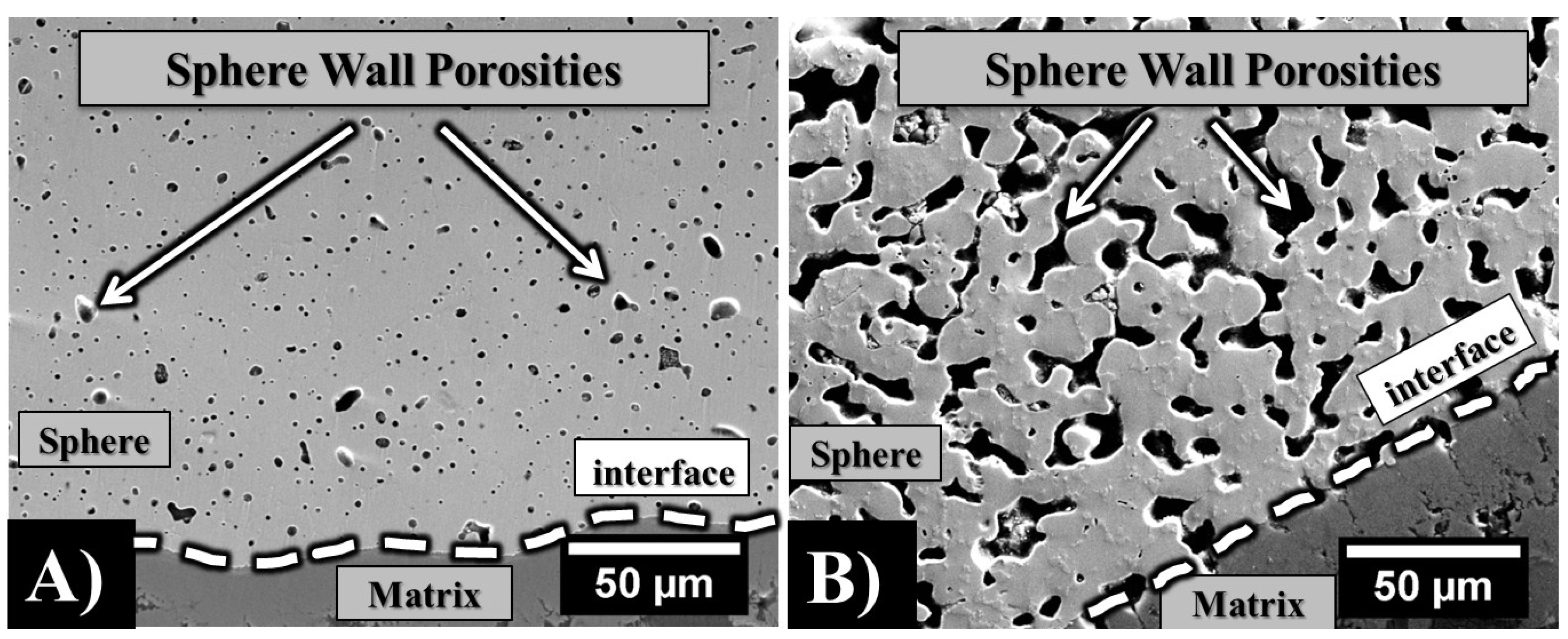
| Sphere Diameter (mm) | Sphere Wall Thickness (μm) | Sphere Wall Porosity (%) | Measured Density (g/cm3) | Estimated Density (g/cm3) |
|---|---|---|---|---|
| 3.7 | 200 | 5.0 | 2.5 | 2.4 |
| 4.0 | 196 | 14.0 | 2.0 | 2.1 |

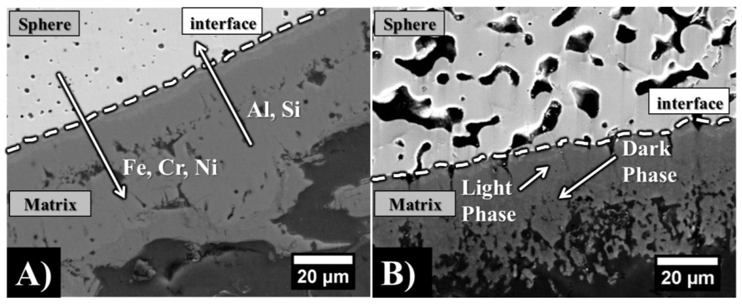
| 3.7 mm | Fe | Cr | Ni | (FeCrNi) | Mn | Mo | Al | Si |
| Intermetallic Layer | 16.40 | 4.10 | 0.00 | 20.50 | 0.40 | 0.00 | 72.00 | 7.90 |
| Plate Shape | 11.91 | 2.11 | 0.03 | 14.05 | 1.11 | 0.02 | 75.96 | 8.87 |
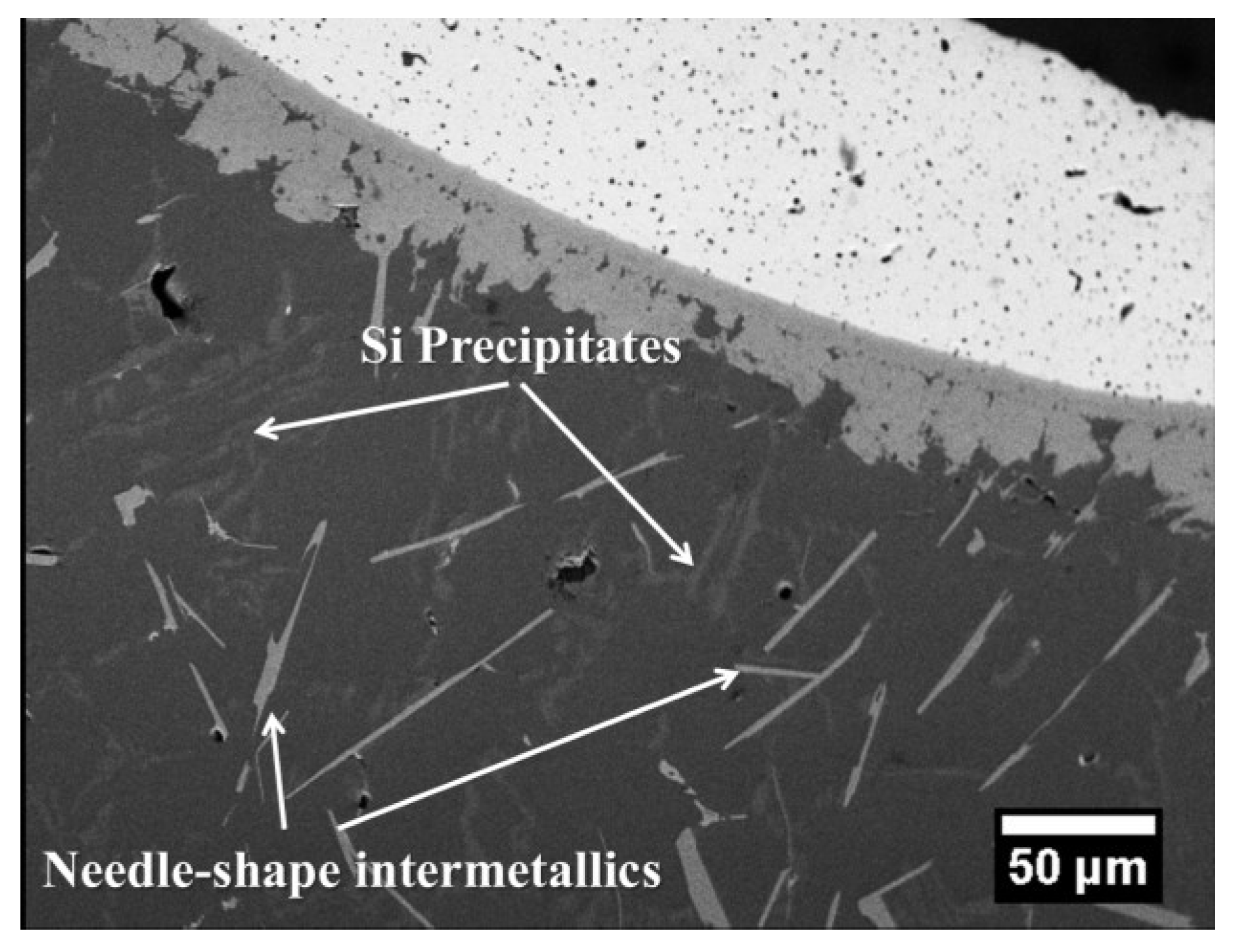
| Needle Shape | 12.57 | 0.02 | 0.06 | 12.65 | 0.22 | 0.00 | 70.93 | 16.21 |
| Si Precipitate | 0.00 | 0.00 | 0.04 | 0.04 | 0.02 | 0.00 | 2.94 | 97.00 |
| Al Matrix | 0.02 | 0.02 | 0.03 | 0.07 | 0.00 | 0.00 | 98.35 | 1.58 |
| 4.0 mm | Fe | Cr | Ni | (FeCrNi) | Mn | Mo | Al | Si |
| Intermetallic Layer (Light) | 19.27 | 3.56 | 1.42 | 24.25 | 0.07 | 0.17 | 71.32 | 4.19 |
| Intermetallic Layer (Dark) | 8.70 | 3.66 | 0.41 | 12.77 | 0.08 | 0.14 | 80.00 | 7.01 |
| Plate Shape | 13.12 | 3.66 | 0.47 | 17.25 | 0.07 | 0.00 | 75.37 | 5.91 |
| Needle Shape | 5.76 | 0.01 | 3.14 | 8.91 | 0.00 | 0.00 | 85.78 | 3.33 |
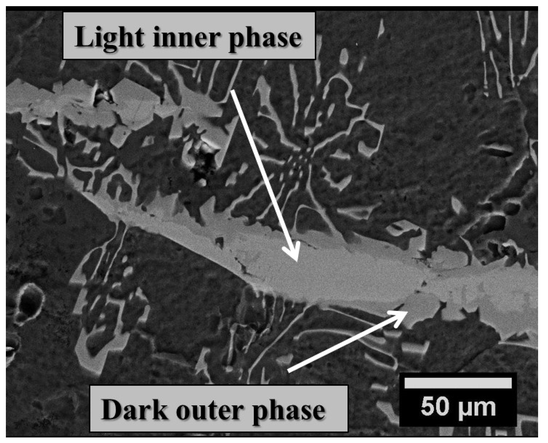
| Branch-like Phase (inner light) | 17.00 | 2.47 | 1.43 | 20.90 | 0.80 | 0.00 | 76.67 | 2.38 |
| Branch-like Phase (outer dark) | 14.81 | 1.58 | 0.58 | 16.97 | 0.06 | 0.00 | 75.58 | 7.38 |
| Si Precipitate (Not found) | - | - | - | - | - | - | - | - |
| Al Matrix | 0.08 | 0.01 | 0.04 | 0.13 | 0.02 | 0.00 | 98.45 | 1.40 |


3.2. Mechanical Properties
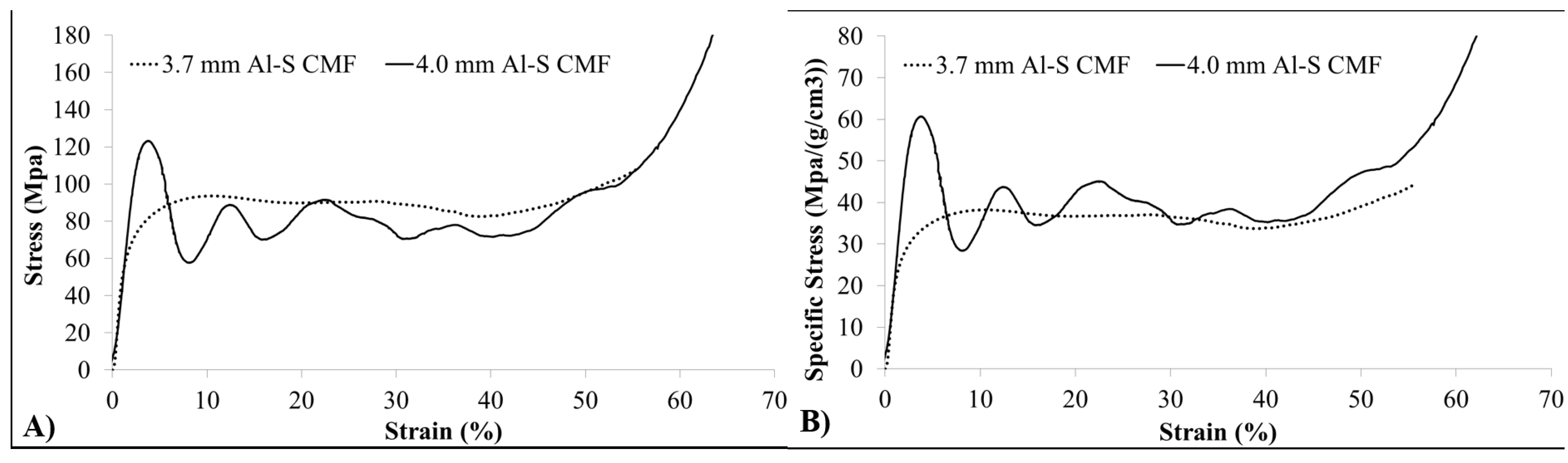
| CMF | Density (g/cm3) | Yield Strength (MPa) | Energy abs. at 50% strain (MJ/m3) | Spec. Energy abs. at 50% strain (J/g) |
|---|---|---|---|---|
| 3.7 mm | 2.5 | 52 | 43.31 | 17.32 |
| 4.0 mm | 2.0 | 110 | 40.02 | 20.01 |
4. Discussion
4.1. Effect of Sphere Surface Roughness and Wall Porosity
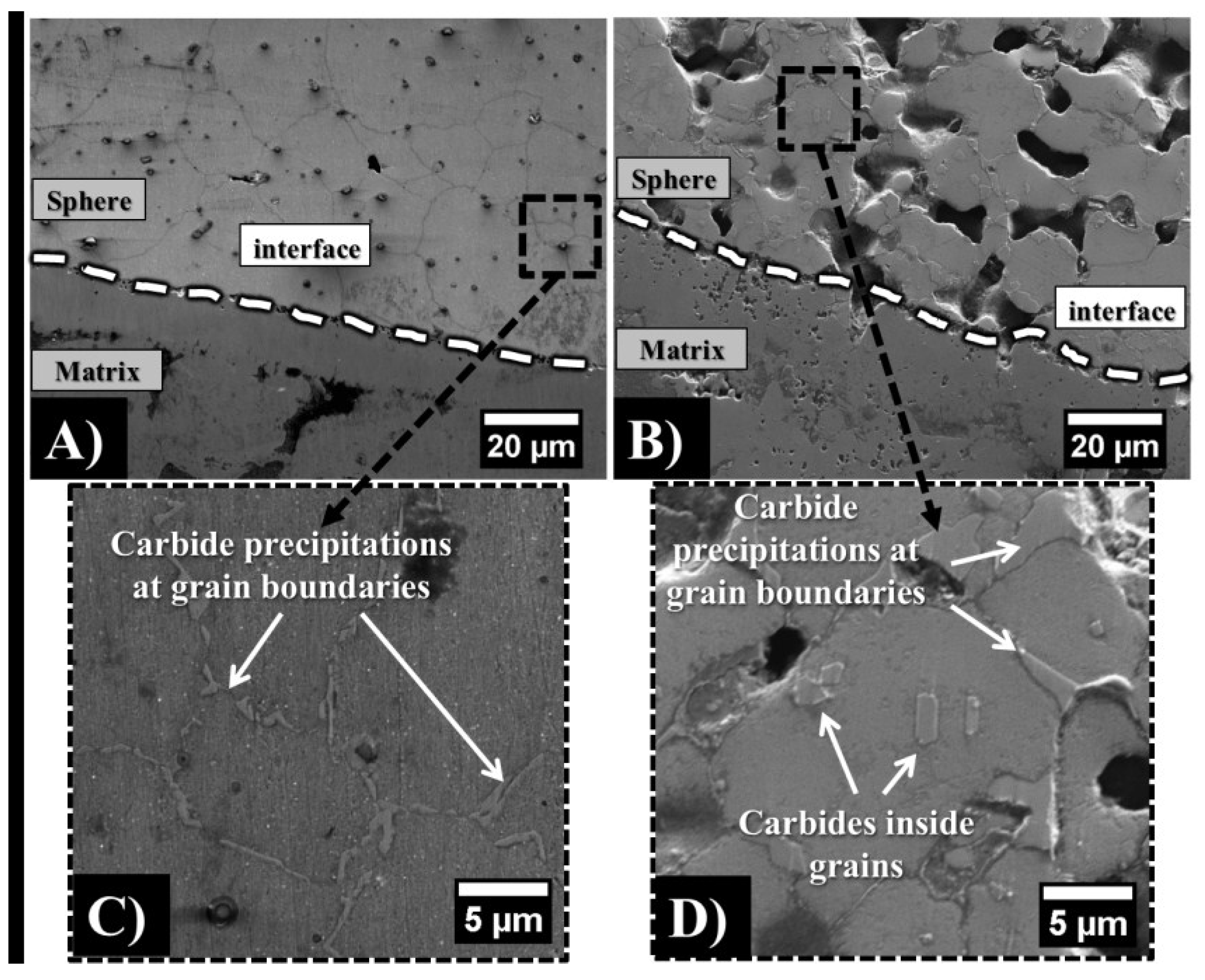
4.2. Effect of Sphere Wall Carbon Content and Chemical Composition
5. Conclusions
Author Contributions
Conflicts of Interest
References
- Rabiei, A.; O’Neill, A.T. A study on processing of a composite metal foam via casting. Mater. Sci. Eng. A 2005, 404, 159–164. [Google Scholar] [CrossRef]
- Rabiei, A.; Vendra, L.; Reese, N.; Young, N.; Neville, B.P. Processing and characterization of a new composite metal foam. Mater. Trans. 2006, 47, 2148–2153. [Google Scholar] [CrossRef]
- Vendra, L.J.; Rabiei, A. A study on aluminum-steel composite metal foam processed by casting. Mater. Sci. Eng. A 2007, 465, 59–67. [Google Scholar] [CrossRef]
- Rabiei, A.; Vendra, L.J. A comparison of composite metal foam’s properties and other comparable metal foams. Mater. Lett. 2009, 63, 533–536. [Google Scholar] [CrossRef]
- Vendra, L.; Rabiei, A. Evaluation of modulus of elasticity of composite metal foams by experimental and numerical techniques. Mater. Sci. Eng. A 2010, 527, 1784–1790. [Google Scholar] [CrossRef]
- Rabiei, A.; Neville, B.; Reese, N.; Vendra, L. New composite metal foams under compressive cyclic loading. Mater. Sci. Forum 2007, 539–543, 1868–1873. [Google Scholar] [CrossRef]
- Vendra, L.; Neville, B.; Rabiei, A. Fatigue in aluminum-steel and steel-steel composite foams. Mater. Sci. Eng. A 2009, 517, 146–153. [Google Scholar] [CrossRef]
- Vendra, L.J.; Brown, J.A.; Rabiei, A. Effect of processing parameters on the microstructure and mechanical properties of Al-steel composite foam. Mater. J. Sci. 2011, 46, 4574–4581. [Google Scholar] [CrossRef]
- Gupta, S.P. Intermetallic compound formation in Fe-Al-Si ternary system: Part I. Mater. Charact. 2002, 49, 269–291. [Google Scholar] [CrossRef]
- Maitra, T.; Gupta, S.P. Intermetallic compound formation in Fe-Al-Si ternary system: Part II. Mater. Charact. 2002, 49, 293–311. [Google Scholar] [CrossRef]
- Barbier, F.; Manuelli, D.; Bouché, K. Characterization of aluminide coatings formed on 1.4914 and 316L steels by hot-dipping in molten aluminum. Scr. Mater. 1997, 36, 425–431. [Google Scholar] [CrossRef]
- Colin, C.; Marchal, Y.; Boland, F.; Delannay, F. Stainless steel fibre reinforced aluminum matrix composites processed by squeeze casting: Relationship between processing conditions and interfacial microstructure. J. Phys. IV 1993, 03, 1749–1752. [Google Scholar]
- Frutos, E.; González-Carrasco, J.L.; Capdevila, C.; Jiménez, J.A.; Houbaert, Y. Development of hard intermetallic coatings on austenitic stainless steel by hot dipping in an Al-Si alloy. Surf. Coat. Technol. 2009, 203, 2916–2920. [Google Scholar] [CrossRef]
- Warmuzek, M.; Gazda, A.; Anal, J. An analysis of cooling rate influence on the sequence of intermetallic phases precipitation in some commercial aluminum alloys. At. Spectrom. 1999, 14, 535–537. [Google Scholar] [CrossRef]
- Wang, Y.; Jones, H.; Evans, P.V. Eutectic solidification characteristics of Bridgman grown Al-3Fe-0.1V alloy. Mater. J. Sci. 1998, 33, 5205–5220. [Google Scholar] [CrossRef]
- Andersen, O.; Waag, U.; Schneider, L.; Stephani, G.; Kieback, B. Novel metallic hollow sphere structures. Adv. Eng. Mater. 2000, 2, 192–195. [Google Scholar] [CrossRef]
- Stephani, G.; Kupp, D.; Claar, T.D.; Waag, U. Fabrication of Ti-based components with controlled porosity. Int. Conf. Powder Metall. Part. Mater. 2001, 50–58. [Google Scholar]
- Image J. Software. Available online: http://rsbweb.nih.gov/ij (accessed on 18 May 2015).
- Ashby, M.F.; Evans, A.G.; Fleck, N.A.; Gibson, L.J.; Hutchinson, J.W.; Wadley, H.N.G. Metal Foams, A Design Guide; Butterworth-Heinemann: Woburn, MA, USA, 2000. [Google Scholar]
- Rabiei, A.; Garcia-Avila, M. Effect of various parameters on properties of composite steel foams under variety of loading rates. Mater. Sci. Eng. A 2013, 564, 539–547. [Google Scholar] [CrossRef]
- Viala, M.; Peronnet, M.; Barbeau, F.; Bosselet, F.; Bouix, J. Interface chemistry in aluminium alloy castings reinforced with iron base inserts. Compos. Part A Appl. Sci. Manuf. 2002, 33, 1417–1420. [Google Scholar] [CrossRef]
- Han, Y.; Ban, C.; Zhang, H.; Nagaumi, H.; Ba, Q.; Cui, J. Investigations on the solidification behavior of Al-Fe-Si alloy in an alternating magnetic field. Mater. Trans. 2006, 47, 2092–2098. [Google Scholar] [CrossRef]
- Barros, J.; Malengler, B.; van Keer, R.; Houbaert, Y. Modeling silicon and aluminum diffusion in electrical steel. JPEDAV 2005, 26, 417–422. [Google Scholar] [CrossRef]
- Cheng, W.J.; Wang, C.J. Microstructural evolution of intermetallic layer in hot-dipped aluminide mild steel with silicon addition. Surf. Coat. Technol. 2011, 205, 4726–4731. [Google Scholar] [CrossRef]
- Durand-Charre, M. Microstructure of Steels and Cast Irons; Springer: New York, NY, USA, 2004. [Google Scholar]
© 2015 by the authors; licensee MDPI, Basel, Switzerland. This article is an open access article distributed under the terms and conditions of the Creative Commons Attribution license (http://creativecommons.org/licenses/by/4.0/).
Share and Cite
Garcia-Avila, M.; Rabiei, A. Effect of Sphere Properties on Microstructure and Mechanical Performance of Cast Composite Metal Foams. Metals 2015, 5, 822-835. https://doi.org/10.3390/met5020822
Garcia-Avila M, Rabiei A. Effect of Sphere Properties on Microstructure and Mechanical Performance of Cast Composite Metal Foams. Metals. 2015; 5(2):822-835. https://doi.org/10.3390/met5020822
Chicago/Turabian StyleGarcia-Avila, Matias, and Afsaneh Rabiei. 2015. "Effect of Sphere Properties on Microstructure and Mechanical Performance of Cast Composite Metal Foams" Metals 5, no. 2: 822-835. https://doi.org/10.3390/met5020822