Article

A Comparative Characterization of the Microstructures and Tensile Properties of As-Cast and Thixoforged in situ AM60B-10 vol% Mg2Sip Composite and Thixoforged AM60B

Key Laboratory of Advanced Processing and Recycling of Nonferrous Metals, Lanzhou University of Technology, Lanzhou 730050, China
*
Author to whom correspondence should be addressed.
Metals 2015, 5(1), 457-470; https://doi.org/10.3390/met5010457
Submission received: 30 December 2014 / Revised: 28 February 2015 / Accepted: 5 March 2015 / Published: 13 March 2015
(This article belongs to the Special Issue Casting Alloy Design and Modification)

Abstract

:
The microstructure and tensile properties of the thixoforged in situ Mg2Sip/AM60B composite were characterized in comparison with the as-cast composite and thixoforged AM60B. The results indicate that the morphology of α-Mg phases, the distribution and amount of β phases and the distribution and morphology of Mg2Si particles in thixoforged composite are completely different from those in as-cast composite. The Mg2Si particles block heat transfer and prevent the α-Mg particles from rotation or migration during reheating. Both the thixoforged composite and thixoforged AM60B alloy exhibit virtually no porosity in the microstructure. The thixoforged composite has the highest comprehensive tensile properties (ultimate tensile strength (UTS)) of 209 MPa and an elongation of 10.2%. The strengthening mechanism of the Mg2Si particle is the additive or synergetic effect of combining the load transfer mechanism, the Orowan looping mechanism and the dislocation strengthening mechanism. Among them, the load transfer mechanism is the main mechanism, and the latter two are minor. The particle splitting and interfacial debonding are the main damage patterns of the composite.

1. Introduction

Magnesium alloys are the lightest commercially-used metals, offer excellent cast-ability, machinability, low density, high specific strength and stiffness, electromagnetic shielding characteristics and are, thus, attractive for applications in the transportation industry, electronic products, portable tools, sporting goods and aerospace vehicles [1,2,3]. Unfortunately, with the rapid expansion of magnesium applications, magnesium alloys suffer from the challenge of meeting the requirements of strength, ductility, fatigue and creep properties under high temperature. Metal-matrix composites possess many advantages over monolithic materials, such as high-temperature mechanical strength, good wear resistance and dimensional stability, and they have been widely used in aircraft, space, defense and automotive industries [4,5]. Thus, the fabrication of magnesium-based composite is a maneuverable and reliable way to overcome these shortcomings by taking full advantage of magnesium alloys [6]. There are several methods to fabricate magnesium-based composite, such as self-propagating high temperature synthesis (SHS), directed reactive synthesis (DRS), mechanical alloying (MA) and reaction spontaneous infiltration (RSI), blend press sintering, disintegrated melt deposition and in situ synthesis [7,8,9,10,11,12,13,14,15]. Alternatively, the in situ synthesis process produces the desired reinforcements via reaction synthesis in melting alloy by adding grain refiner during traditional casting and is a relatively good potential technique with good maneuverability and reliability for industrial manufacturing, because it does not need special treating procedures and equipment. In the authors’ previous investigations, uniform distribution and dispersion of fine-grained, in situ Mg2Sip/AM60B composite have been achieved via traditional gravity casting by the addition of 0.5 wt% Sr and 0.2 wt% SiCp [16]. Modified Mg2Si particles with a grain size of 20~40 μm were uniformly distribute in the matrix.
As a novel metal process manufacturing, thixoforging involves the advantages of both casting and forging technologies and significantly decreases or even eliminates porosities [2,17]. Consequently, superior tensile properties of the thixoforged components resulting from the pore-free fine microstructure can be achieved. Moreover, the amount and size of the β phase (Mg17Al12), which is harmful for the tensile properties of the alloy, can also be reduce. Therefore, it can be supposed that fabrication of thixoforged in situ Mg2Sip/AM60B composite is a promising way to further expand the applications of AM60B alloy. However, limited information on thixoforged in situ Mg2Sip/AM60B composite is available in the open literature.
This article presents the progress of an ongoing research work on thixoforged in situ Mg2Sip/AM60B composite. The microstructure, tensile properties and fracture behavior of in situ Mg2Sip/AM60B composite are studied. The informative results are compared with identical as-cast composites and thixoforged AM60B alloy, in order to elucidate the strengthening mechanisms of the thixoforging technique and Mg2Si particles.

2. Experimental Section

2.1. As-Cast Preparation

The in situ Mg2Sip/AM60B composites used in this work were prepared by the traditional gravity casting route using commercial AM60B magnesium alloy, pure Mg (99.9 wt%) and Al-30Si (all of them were provided by Changfeng factory in Lanzhou, China). Homemade Mg-30Sr master alloys and Mg-25SiCp press cake (mixture powders) were used as a modifier and grain refiner for the Mg2Si phase and α-Mg phase, respectively. The AM60B alloy was prepared by this method, also, using commercial AM60B magnesium alloy by the addition of 0.2 wt% SiCp. The chemical compositions of those materials are listed in Table 1.
A quantity of AM60B alloy, pure Mg and Al-30Si master alloy was melted in an electric resistance furnace at 790 °C and then modified by 0.5% Sr (using Mg-30Sr master alloy). The melt was then isothermally held for 20 min, and 0.2% SiCp (using the pressed cake of Mg-25SiCp mixture powders) was introduced. Finally, the resulting melt was degassed using C2Cl6 and poured into a steel mold with a cavity of ϕ 50 mm × 500 mm after it had been held for 10 min. Thus, the as-cast composite with 10 vol% Mg2Sip was obtained (as-cast in situ AM60-10 vol% Mg2Sip composite). The melting process of AM60B alloy is similar to the composite, melted at 790 °C and refined by 0.2% SiCp. Owing to the Mg2Si phase being absent, the Mg-30Sr is not necessary to add to this melting alloy. Then, after the melt was degassed by C2Cl6, it was poured into the same mold. A covering agent of RJ-2 (Hongguang Company, Shanghai, China) designed for magnesium alloys was used for protecting the melt from oxidation during both of the melting processes.
Table 1. Chemical composition (in wt%) of the materials studied.
MaterialsAlSiMnZnCuNiFeMg
As-cast composite5.5–6.52.000.24–0.6≤0.22≤0.010≤0.002≤0.005Balance
Thixoforged composite5.5–6.52.000.24–0.6≤0.22≤0.010≤0.002≤0.005Balance
Thixoforged AM60B5.5–6.5≤0.050.24–0.6≤0.22≤0.010≤0.002≤0.005Balance

2.2. Thixoforging Process

For the thixoforging, some ingots with dimensions of ϕ 42 mm × 30 mm were cut from the as-cast rods and then reheated in a resistant furnace under argon gas protection at a semisolid temperature of 600 °C for 60 min. The obtained semisolid feedstocks were quickly handed into a die with a cavity of ϕ 50 mm × 20 mm and then thixoforged using a hydraulic press. The preheating temperature of the die was 300 °C; the applied punch velocity and pressure were 60 mm/s and 192 MPa, respectively. The holding time was 20 s. Repeating the above experimental procedures, thixoforging composite (10 vol% Mg2Sip containing) and AM60B alloy were obtained.

2.3. Microstructural Analysis

The metallographic specimens were cut from the center region of each product and the cross-section polished by standard metallographic techniques. Subsequently, they were chemically etched using 4% nitric acid ethanol solution and observed on an optical microscope (OM, Nikon Instruments, Shanghai, China) and a scanning electron microscope (SEM, NEC Electronics Corporation, Tokyo, Japan). The compositions of the primary α-Mg phase in the microstructures were examined by energy dispersive spectroscopy (EDS, NEC Electronics Corporation, Tokyo, Japan) using spot scan mode in the SEM. The average of at least five primary α-Mg phases was taken as the composition of each specimen. Porosity was evaluated via measuring the optical micrograph of the un-etched metallographic specimens. The related images were analyzed by Image-Pro Plus 5.0 software (Media Cybernetics Company, Silver Spring, MD, USA), and the percentage of the porosity to the whole was quantitatively examined and the results based on the average of three images.

2.4. Tensile Testing

The mechanical properties of the materials were evaluated by tensile testing, which was performed at ambient temperature on a universal material testing machine with a loading velocity of 1 mm/s. Samples for tensile testing with a cross-section of 1.2 mm × 2.5 mm and a gauge length of 10 mm were machined by a Computer Numerical Control (CNC) wire-cut machine (Taizhou Dengfeng CNC Machine Company, Taizhou, China) from the center of each product. The tensile properties of each product, including ultimate tensile strength (UTS) and elongation to failure (Ef), were obtained based on the average of at least five tests. Some typical fracture surfaces and side views of fracture surface were observed on the SEM and OM, respectively, to ascertain the nature of the fracture mechanisms.

3. Results and Discussion

3.1. Microstructural Analysis

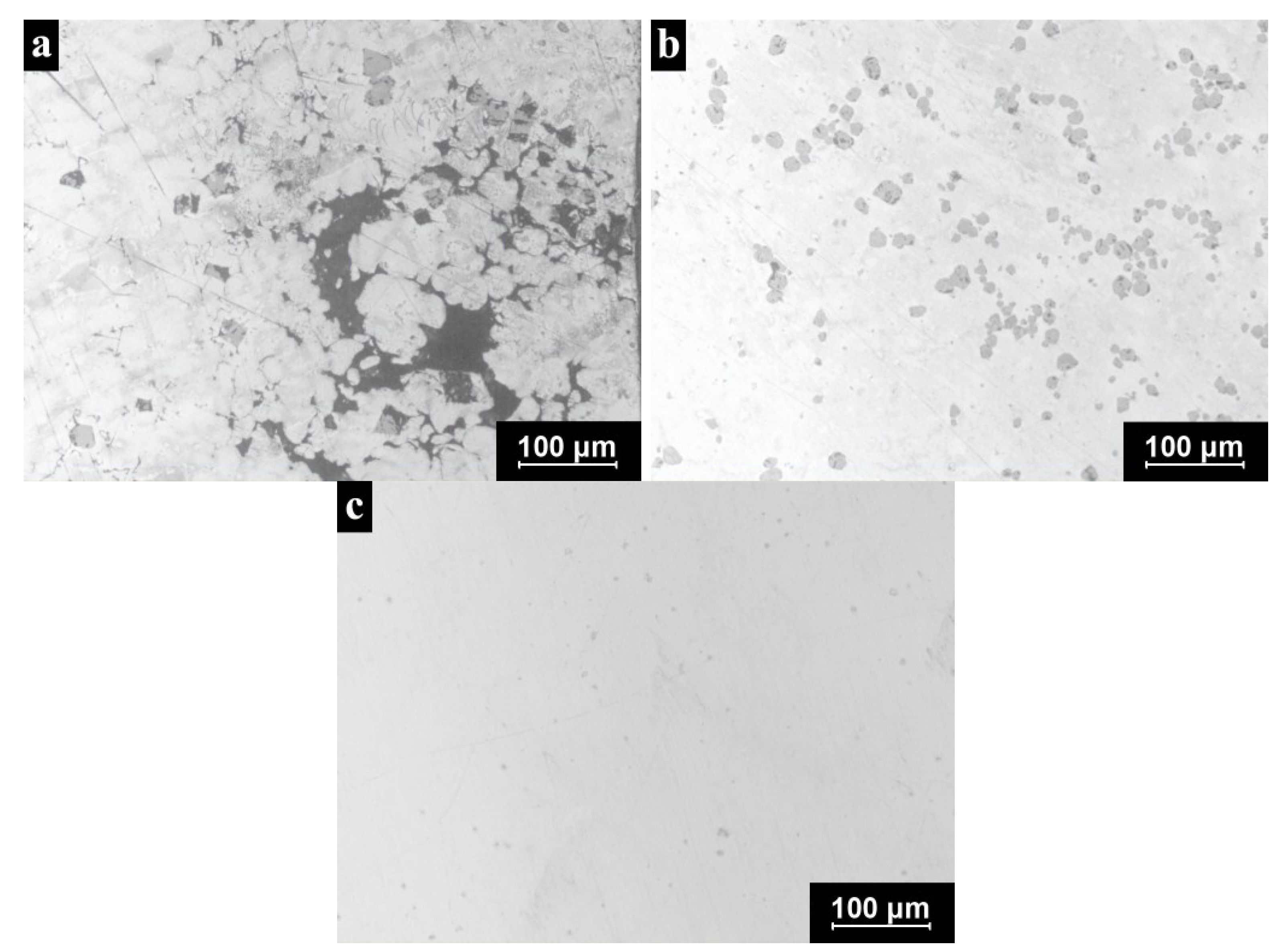
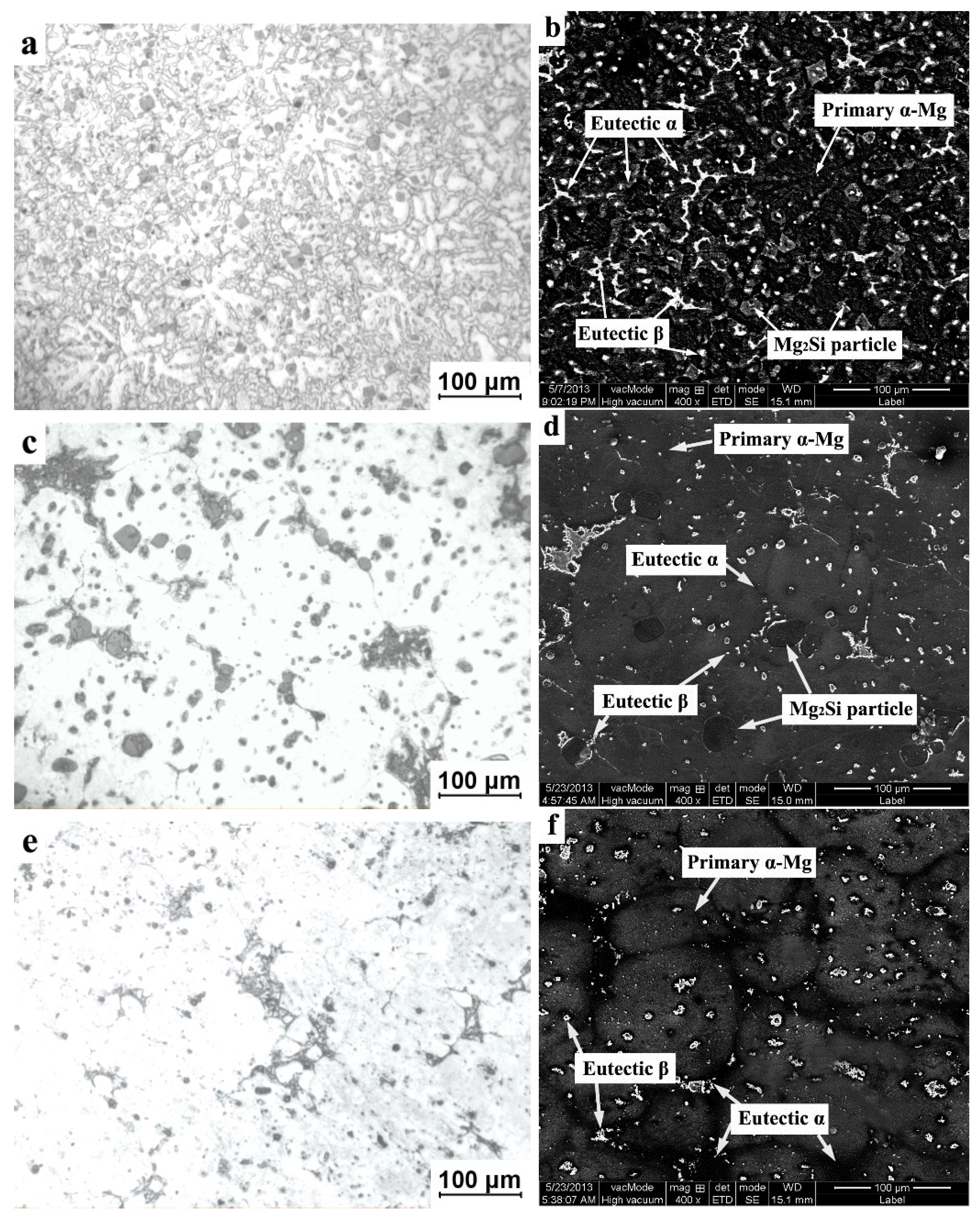
Figure 1 presents the microstructures of the as-cast composite, the thixoforged composite and AM60B revealed by OM and SEM, respectively. The microstructure of the as-cast composite mainly consists of primary α-Mg dendrites, Mg2Si particles and eutectic phases (Figure 1a). The size of the primary α-Mg dendrites is around 70~90 μm, which is relatively large compared with the reported value in the literature [18,19]. This is primarily due to the somewhat slow solidification rate taking place in the current work. The diameter of the mold in this work is 50 mm, which is only 16 mm in the literature. The primary Mg2Si particles with a size of 15~30 μm were located at the primary α-Mg dendrite boundaries. The SEM result (Figure 1b) displays that the β-Mg17Al12 eutectic phase (bright contrast) belongs to divorced eutectics and tend to form a network surrounding the α-Mg phase (dark contrast). According to the Mg-Al binary phase diagram [20], it is known that AM60B alloy is a hypoeutectic alloy, since its Al content and composition is far away from the eutectic point. Under this circumstance, the residual liquid amount should be very low when the eutectic reaction occurs and exists in thin layers between the primary α-Mg dendrites and dendrite arms. Then, the eutectic α phase preferentially directly grows on the primary α-Mg phase without renucleation, and only the eutectic β and eutectic Mg2Si phases are left in the interdendritic regions. The previously-formed primary Mg2Si particles are pushed to the interdendritic regions by the growing interface.
As shown in Figure 1c, the microstructure of the thixoforged composite is composed of primary α-Mg particles, secondarily solidified structures and Mg2Si particles. The morphology of the primary α-Mg particles and the distribution of both the eutectic β phases and Mg2Si particles are completely different from those present in the as-cast composite. The primary α-Mg particles coarsen and connect to each other, the size being approximately 90~120 μm, which is significantly larger than the primary α-Mg dendrites in as-cast microstructure. The Mg2Si particles coarsen, as well, and their size is about 30~40 μm. The sharp edges and corners become blunt. However, the Mg2Si particles in the thixoforged coupon not only surround the primary α-Mg particles, but also some of them locate inside the primary α-Mg particles. The size and amount of the β phase clearly decrease in the thixoforged specimen, which is located at the boundaries and inside the primary α-Mg particles, as well (shown in Figure 1d). Figure 1e presents the microstructure of the thixoforged AM60B alloy. It indicates that the primary α-Mg particles slightly coarsen, and the outline becomes indistinct (comparing Figure 1f with 1d). The secondarily solidified structures almost disappear and only can be found in some triple point. As shown in Figure 1f, the β phase size and amount of both the thixoforged composite and AM60B alloy are at a comparable level.
The morphological change of the α-Mg phase occurs during the reheating process. The thixoforged composites are subjected to a partial remelting treatment. During this technical process, the primary α-Mg dendrites transform into spheroidal primary α-Mg particles uniformly suspended in the liquid phase. During the subsequent thixoforging, the liquid solidifies to form secondarily-solidified structures. Coarsening of the primary α-Mg grains in the thixoforged specimen should be attributed to the following two aspects. One is Ostwald ripening and the coalescence of the nearby primary α-Mg grains during reheating, driven by minimizing the interfacial energy [21]. Grain growth by coalescence by grain boundary migration is dominant for short times after the liquid is formed, and Ostwald ripening is dominant for longer times [22]. This is a common phenomenon in thixoforged materials [23,24,25]. The Mg2Si particles and the liquid might be engulfed by the merged primary α-Mg grains, so Mg2Si particles or the eutectic β phase would distribute inside the primary α-Mg grains in the thixoforged specimens. The other is the solidification behavior of the thixoforged materials. Table 2 gives the compositions of α-Mg phase under these three methods. It reveals that the Al concentration in these two thixoforged materials is significantly higher than that in the as-cast coupon. This is because the eutectic phase is dissolving towards the primary α-Mg grains during reheating, which results in the Al concentration increase in the primary α-Mg grains and a decrease in the liquid. In this case, the formed secondarily primary α-Mg phase (to differentiate the primary α-Mg grains, the primary α-Mg phase solidified form of the liquid is named the secondarily primary α-Mg phase) and the eutectic α-Mg phase should increase, accompanied by the decrease of the eutectic β phase (the Al element is a necessary constituent for forming the eutectic β phase). The secondarily primary α-Mg phase should preferentially directly grow on the surfaces of the primary α-Mg grains, and then, the eutectic α-Mg phase also preferentially attaches on the surfaces of the secondarily primary α-Mg phase, which leads to the primary α-Mg grains coarsening and connecting with each other.
Although the reheating temperature of 600 °C is lower than the eutectic point of Mg-Mg2Si (637.6 °C) [20], the primary Mg2Si particles and eutectic Mg2Si phases should partially melt due to the penetration of the liquid and diffusion of Mg and Si atoms between Mg2Si and liquids, especially at the sharp edges and corners. During the thixoforging, the melted Mg2Si (including primary and eutectic Mg2Si phases) grows as halos surrounding the nearly spherical Mg2Si particles. Therefore, the Mg2Si particles are somewhat coarse and spherical in the thixoforged specimen compared to those in the as-cast specimen.
With regard to the Mg2Si particles, two primary factors affect the semisolid microstructural evolution, as described in this section. Firstly, the Mg2Si particle acting as a ceramic phase with the low thermal conductivity, which uniformly distributes in the matrix, would block the heat transfer from the edge to the center of the semisolid ingot [26]. This would suggest that the heating rate is delayed, so that the phase transformation rate is reduced. It is known that the microstructure evolution closely depends on the phase transformation. Therefore, coarsening from Ostwald ripening is suppressed. This would also affect the composition of the primary α-Mg grains simultaneously. On the other hand, the pin effect of the Mg2Si particles in the primary α-Mg boundary prevent the primary α-Mg boundary from rotation or migration [27]. Thus, the coalescence of the contacted primary α-Mg grains through mergence would be suppressed. As a result, the size and Al solubility of the primary α-Mg grains in thixoforged composite are slightly lesser than in the thixoforged AM60B alloy. Based on these standpoints, it is no difficult to understand the resultant microstructures under those different processing technologies.
Figure 1. OM micrographs and SEM images of: (a,b) as-cast composite; (c,d) thixoforged composite; and (e,f) thixoforged AM60B.
Metals 05 00457 g001
Table 2. Compositions of primary α-Mg dendrites or the grains of these materials.
MaterialsCompositions/wt%
AlMg
As-cast composite4.7495.26
Thixoforged composite6.8793.13
Thixoforged AM60B7.2092.80

3.2. Porosity Evaluation

Figure 2 reveals the porosity distribution in the polished specimens. Representative pores can be easily spotted in the as-cast composite, as indicated in Figure 2a. However, it is evidently shown in Figure 2b,c that the thixoforged coupons are virtually free of gas and shrinkage porosities. In comparison with that (4.00%) of the as-cast composite, the porosity percentage of the thixoforged composite is 0.15%, and the thixoforged AM60B is 0.12%.
The porosity elimination of thixoforged ingots should result from the following reasons. The first is the high applied pressure during solidification and low filling velocity during mold filling. The high applied pressure reduces the shrinkage porosity by squeezing the liquid metal into the last region of the casting to solidify. Thus, the feeding ability to solidification shrinkage is enhanced. The purpose of the low filling velocity is to effectively avoid air entrapment. The second is the inherent characteristic of the semisolid forming [2,5,17]. The spherical morphology of the primary α-Mg grains would be more favorable to liquid penetration for feeding [28]. The proper liquid fraction of the thixoforging, which is lower than that of the traditional casting, should reduce the probability of the solidification shrinkage and effectively avoid entrapped gas, as well.
Figure 2. Optical micrographs showing porosity in: (a) as-cast composite; (b) thixoforged composite; and (c) thixoforged AM60B.
Metals 05 00457 g002

3.3. Tensile Properties

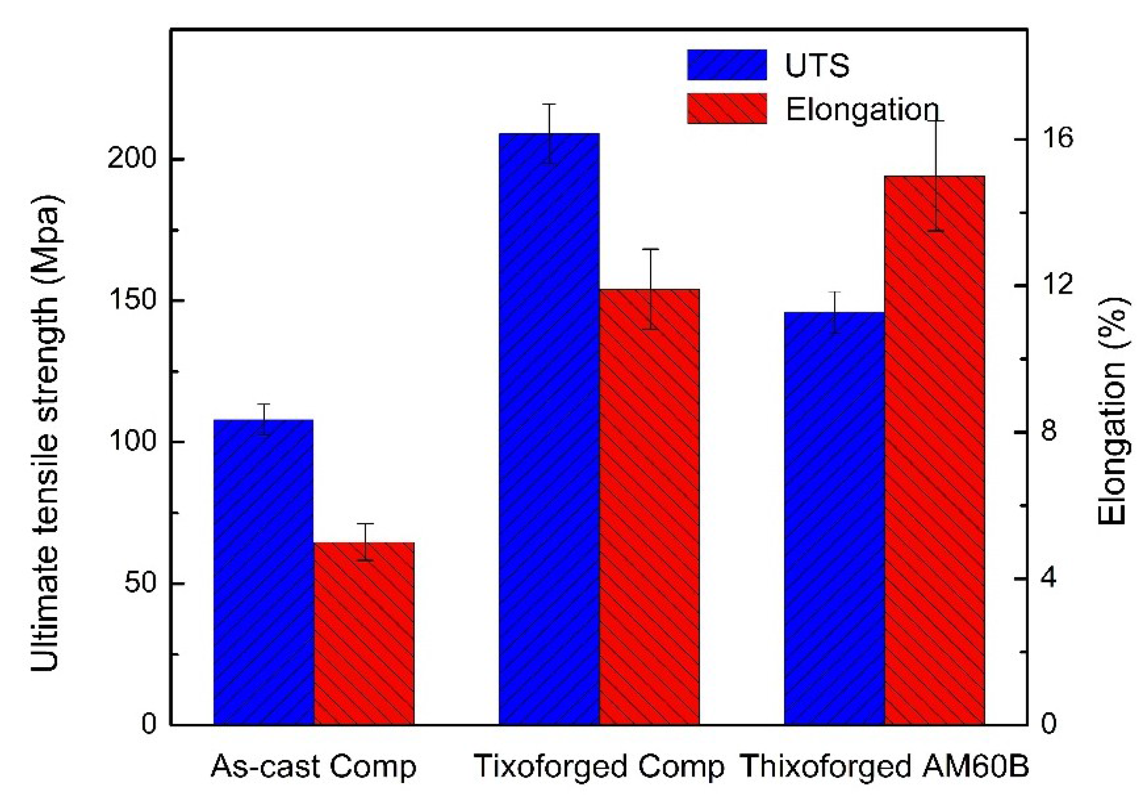
Figure 3 gives the tensile properties of those three materials. It can be evidently seen from Figure 3 that the UTS of the thixoforged composite is 209 MPa, which is significantly higher than that of the as-cast conditions (108 MPa) and the thixoforged AM60B alloy (146 MPa). However, the elongation of the thixoforged AM60B is 13.3%, which is the maximum value among these three materials. The thixoforged composite has the highest comprehensive tensile properties, UTS of 209 MPa and elongation of 10.2%.
Figure 3. Tensile properties of the materials at room temperature. UTS, ultimate tensile strength.
Metals 05 00457 g003
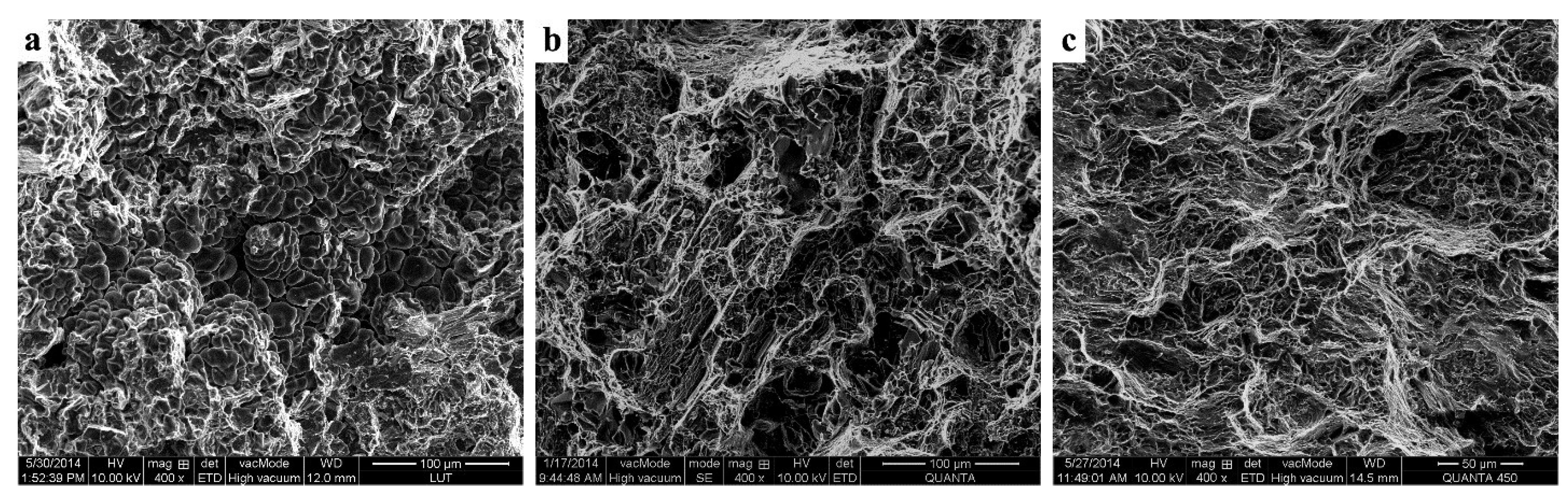
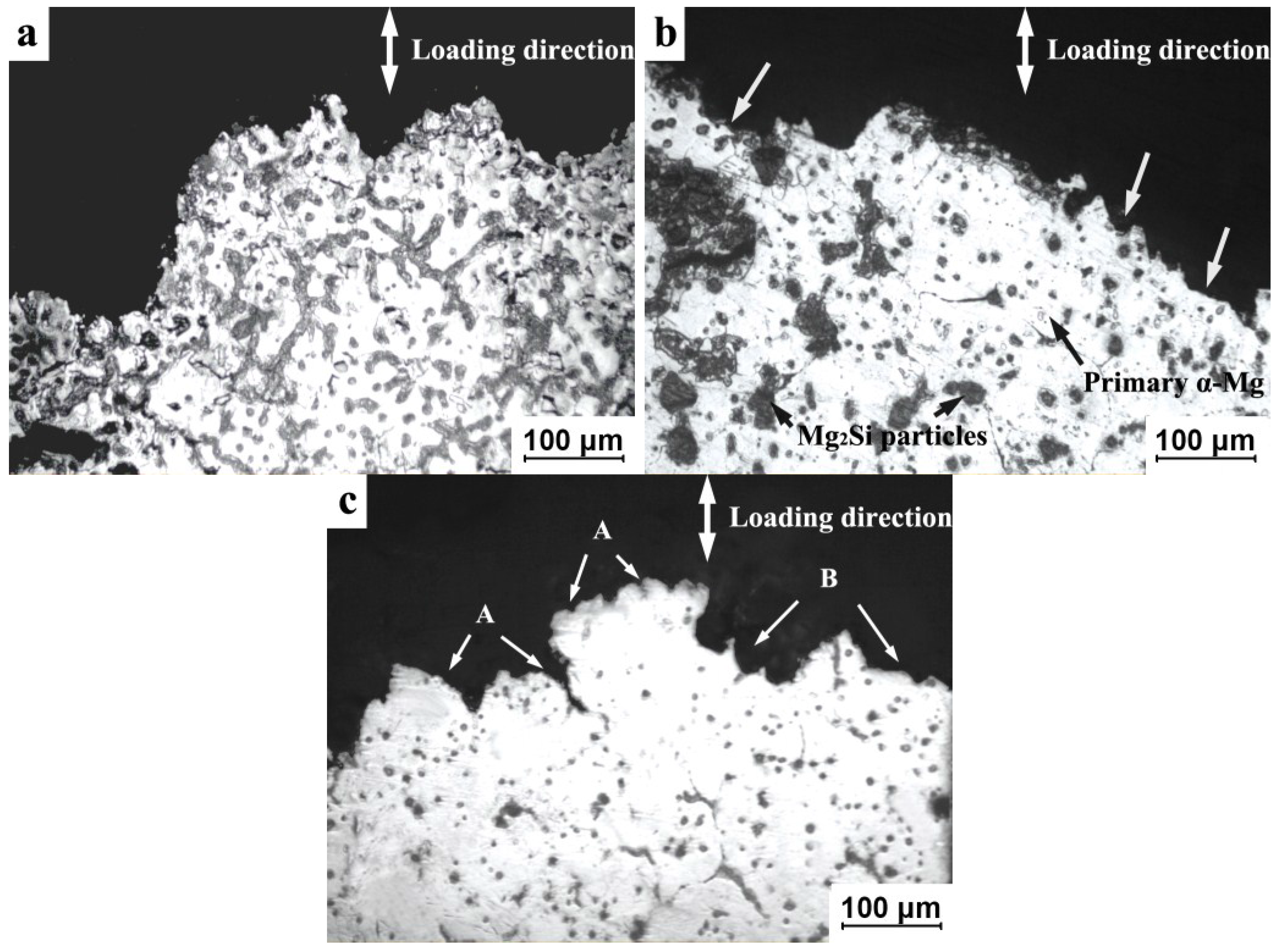
Figure 4 shows the typical fractographs of these three materials. It indicates that the fracture surface of the as-cast composite is characterized by porosity features (Figure 4a), which are somewhat brittle in nature. As mentioned above, the porosities can be obviously observed from the micrograph of as-cast composite, which should generate in the last solidified zones, i.e., the eutectic structures between the primary α-Mg dendrites. The porosities serve as the initiation point of cracks in the as-cast specimens. Then, the cracks grow and propagate along the eutectic structures during tensile testing, which is depicted in Figure 5a. The failure is mainly attributed to the intergranular fracture and is partially caused by the segregation of the brittle eutectic β phase at dendrite boundaries. As described in the previous section, the thixoforged composite is virtually free of gas and shrinkage porosities. Correspondingly, the porosity characteristics on the fracture surface of the thixoforged composite disappear and are substituted by small dimples (Figure 4b). Plenty of fractured Mg2Si particles could be observed on the fracture surface. The crack propagation path turns from along the eutectic structures into across the primary α-Mg grains (Figure 5b, marked by arrows). The failure transfers to the transgranular fracture mode. The resultant fractographs and side-view of the fractured surfaces of both the as-cast and thixoforged composite are in good agreement with the data of tensile properties shown in Figure 3. It is well established that the tensile properties of the material are determined by their microstructures. Therefore, it is concluded that the elimination of porosity, the decrease of the eutectic β phase and enhancement of solution strengthening are responsible for the superior tensile properties of the thixoforged composite.
Figure 4c illustrates the fracture surface of the thixoforged AM60B alloy, which is characterized by small dimples and flat facets. The dimples result from localized microvoid coalescence, due to the dislocation motion or grain boundary sliding. The microvoids grow and connect, eventually leading to the creation of cracks. The flat facets are caused by cracks moving through the primary α-Mg grains. Cracks propagate between the primary α-Mg grains (marked by A) and occasionally across the primary α-Mg grains (marked by B) in some local zones (Figure 5c), which is consistent with the fracture surface. The fracture of the thixoforged AM60B belongs to a mixture of transgranular and intergranular modes. The inferior UTS of the thixoforged AM60B should be ascribed to there being no reinforcing phase to strengthen the α-Mg phase. A large amount of eutectic β phase is a harmful effect for UTS. However, the amount of the β phase reduced to a given value may also decrease the UTS, owing to the strengthening role of the β phase being reduced. This is also the same reason that results in the superior elongation of this alloy. However, the adopted technologic parameters (reheating time and temperature, mold preheating temperature, etc.) in this work are optimum for the thixoforged composite. There may not be optimized parameters for the thixoforged AM60B alloy. It can be reasonably concluded that the tensile properties of the thixoforged AM60B alloy will be further improved through adjusting the technologic parameters. This will be discussed in further work.
Figure 4. SEM fractographs of: (a) as-cast composite; (b) thixoforged composite and (c) thixoforged AM60B.
Metals 05 00457 g004
Figure 5. OM images reveal the side-view of the fracture surface: (a) as-cast composite; (b) thixoforged composite; and (c) thixoforged AM60B.
Metals 05 00457 g005

3.4. Strengthening Mechanisms of the Mg2Si Grains

For the purpose of verifying the strengthening mechanism of Mg
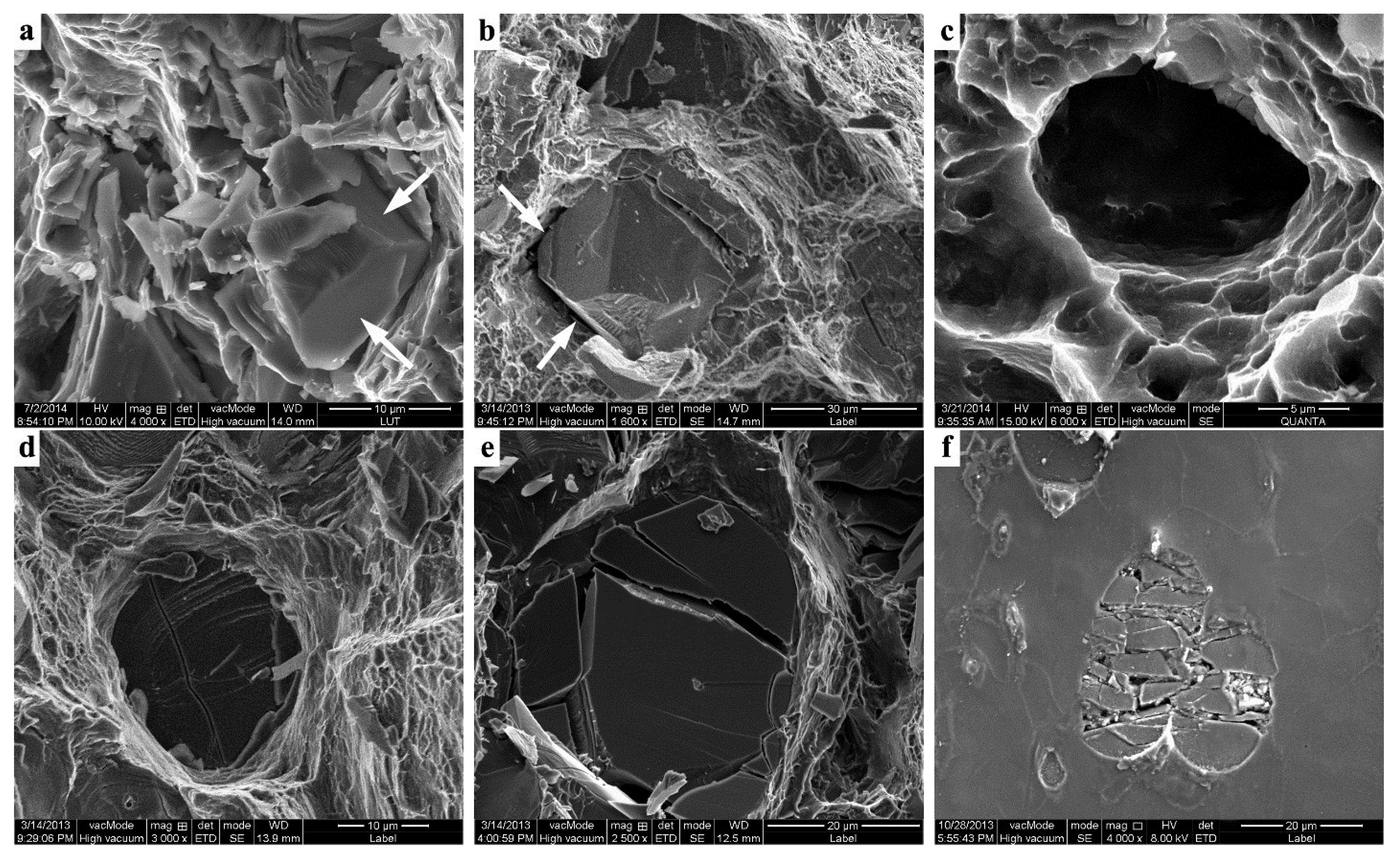
2Si particles for the α-Mg matrix, some typical fracture surfaces are carefully observed with high magnification (Figure 6). Pay attention to the composite in the as-cast condition: the Mg2Si particles can only be found in some local zone on the fracture surface. The Mg2Si particles are surrounded by the deformed α-Mg matrix and keep their original morphology (Figure 6a). During tensile testing, the pin effect of the Mg2Si particles in the grain boundaries keeps them from sliding. The interfaces of the Mg2Sip/matrix belong to an incoherent interface, due to the differences of the crystal structures and the lattice constants [29]. Therefore, local stress concentration should be preferentially generated at the sharp edges and corners of the Mg2Si particles. Therefore, the interfaces of the Mg2Sip/matrix are easily debonded under this local stress (marked by arrows in Figure 6a). Subsequently, the debonding areas extend and connect with the cracks, which initiate from the eutectic structure or porosity, eventually leading to the final fracture. Owing to the non-compact microstructure of the as-cast composite, the reinforcement of Mg2Si particles of the matrix has not fully taken part in the contribution to the improved the tensile properties.
Figure 6. Typical SEM images showing Mg2Si particles in: (a) as-cast composite; (be) the thixoforged composite fracture surface; (f) the thixoforged composite tensile bar.
Metals 05 00457 g006
There are two kinds of failure behaviors related to the Mg2Si particles, which can be found on the thixoforged composite fracture surface. One is the interfacial debonding of Mg2Sip/matrix (Figure 6b). As mentioned above, the sharp edges and corners become blunt. Therefore, the local stresses are uniformly distributed along the Mg2Sip/matrix interfaces and increase as the tensile stress increases. Microvoids should generate in the surrounding matrix under this local stress. Then, the localized microvoids’ coalescence results in the debonding of the interface (Figure 6c). The other is the fragmentation of Mg2Si particles. There are two ways for the Mg2Si particle to fracture: either fractured parallel to the fracture surface of the whole specimen (Figure 6d) or broken into several parts (Figure 6e). The composite mainly contains two phases with very different mechanical behaviors: the α-Mg phase and Mg2Si particles. While the soft magnesium alloy deforms plastically during tensile testing, the Mg2Si particles are rigid and deform only elastically. The reinforcing Mg2Si particles prevent the straining of the surrounding matrix. Thus, the composite is plastically non-homogeneous, because the plastic deformation gradient is imposed on the Mg2Sip/matrix interfaces. Therefore, a high stress concentration generates at the interface and gives rise to the increase of tensile strain. The existing investigation supposed that the stress concentration was two- to four-times higher than that of the α-Mg matrix [30]. When the stress concentration exceeds some value, this should even result in the fragmentation of Mg2Si particles (Figure 6d,e). Figure 6f reveals that the Mg2Si particles split into several parts and that there are no visible cracks in the surrounding matrix. The interfacial debonding and particle fragmentation are the indications of the absorption of energy and the relaxation of local stress concentration. This is just due to the formation of local stress concentration at the Mg2Si/matrix interface and the subsequent relaxation; the growth rate and nucleation of the crack in the surrounding matrix are delayed. Thus, the strengthening of the Mg2Si particles of the matrix should primarily be the result of the load transfer mechanism. The particle splitting and interfacial debonding are the main damage patterns of the composite.
The contribution of Mg2Si particles to improving the mechanical properties should also be attributed to other mechanisms. One is the Orowan looping mechanism, which is described as the interaction between dislocations and fine particles: the resistance of the reinforcing particles to the passage of dislocations from a balance between the force acting on the dislocation and the force coming from the line tension acting on both sides of the reinforcing particle [31]. However, this mechanism is only effective in action when the reinforcing particles are located within the grains. In the composite employed in this work, the Mg2Si particles are mainly located at the boundaries of primary α-Mg grains and occasionally located inside of them. Therefore, the strengthening effect due to the Orowan mechanism will be minor. The other is the dislocation strengthening mechanism, which results from the coefficient of thermal expansion (CTE) mismatch between Mg2Si particles and the matrix: dislocations are created, due to the relaxation of thermal expansion mismatch between reinforcing particles and matrix, and may cause an increase in the dislocation density [32]. This effect can impede the dislocation movement, also playing a very important role in strengthening the matrix.
Although the contribution of each strengthening mechanism to improving the mechanical properties has not been calculated separately, it should also be believed that an additive or synergetic effect probably occurs by combining several mechanisms. Among them, the load transfer mechanism should primarily take part in strengthening the matrix, and the Orowan looping mechanism and dislocation strengthening mechanism should be minor.

4. Conclusions

(1). In comparison with the as-cast composite, the morphology of α-Mg phases, the distribution and amount of β phases and the distribution and morphology of Mg2Si particles in thixoforged composite are completely different from those in as-cast composite.
(2). The α-Mg dendrites evolve into spheroidal α-Mg grains uniformly suspended in the liquid phase during reheating. The liquid solidifies to form a secondarily-solidified structure. The eutectic structure dissolving towards the α-Mg grains results in the β phases’ decrease, and the Al concentration in primary α-Mg grains increases. The β phases and Mg2Si particles are entrapped within the merged α-Mg grains. The coarsening of α-Mg grains results from coalescence, Ostwald ripening and subsequent solidification behavior.
(3). The Mg2Si particles block heat transfer, so as to delay the Ostwald ripening. The pin effect of the Mg2Si particles prevents the α-Mg grains from rotation or migration, so as to reduce the probability of α-Mg grain mergence. The resulting α-Mg grains in the thixoforged composite are slightly finer than that in the thixoforged AM60B alloy.
(4). The porosity elimination in the thixoforged component is attributed to the low filling velocity during mold filling, the applied high press during solidification, the enhanced feeding ability of spherical primary α-Mg grains and the low liquid fraction of the semisolid slurry.
(5). The UTS of the thixoforged composite is 209 MPa, which is significantly higher than that of the as-cast conditions (108 MPa) and the thixoforged AM60B alloy (146 MPa). The thixoforged AM60B has the maximum value of elongation (13.3%). The thixoforged composite has the highest comprehensive tensile properties, UTS of 209 MPa and elongation of 10.2%.
(6). The strengthening mechanism of the Mg2Si particles is the additive or synergetic effect combining the load transfer mechanism, the Orowan looping mechanism and the dislocation strengthening mechanism. Among them, the load transfer mechanism is the main mechanism, and the latter two are minor.

Acknowledgments

The authors wish to express thanks for the financial support from the National Basic Research Program of China (Grant No. G2010CB635106), the Program for New Century Excellent Talents in University of China (Grant No. NCET-10-0023) and the Program for Hongliu Outstanding Talents of Lanzhou University of Technology.

Author Contributions

Tijun Chen and Suqing Zhang conceived and designed the experiments; Suqing Zhang and Faliang Cheng performed the experiments; Faliang Cheng and Pubo Li analyzed the data; Suqing Zhang wrote the paper.

Conflicts of Interest

The authors declare no conflict of interest.

References

  1. Hao, Y.; Chen, T.J.; Ma, Y.; Li, Y.D.; Yan, F.Y.; Huang, X.F. Some key issues and accesses to the application of magnesium alloys. Int. J. Modern Phys. B 2010, 24, 2237–2242. [Google Scholar] [CrossRef]
  2. Fan, Z. Development of the rheo-diecasting process for magnesium alloys. Mater. Sci. Eng. A 2005, 413, 72–78. [Google Scholar] [CrossRef]
  3. Eliezer, D.; Aghion, E.; Froes, F. The science, technology, and applications of magnesium. JOM-US 1998, 50, 30–34. [Google Scholar]
  4. Ji, S.; Qian, M.; Fan, Z. Semisolid processing characteristics of AM series Mg alloys by rheo-diecasting. Metal. Mater. Trans. A 2006, 37A, 779–787. [Google Scholar] [CrossRef]
  5. Flemings, M.C. Solidification processing. Metal. Mater. Trans. B 1974, 5, 2121–2134. [Google Scholar]
  6. Gadow, R. Lightweight engineering with advanced composite materials-ceramic and metal matrix composites. Adv. Sci. Technol. 2006, 50, 163–173. [Google Scholar] [CrossRef]
  7. Song, M.S.; Zhang, M.X.; Zhang, S.G.; Huang, B.; Li, J.G. In situ fabrication of TiC particulates locally reinforced aluminum matrix composites by self-propagating reaction during casting. Mater. Sci.Eng. A 2008, 473, 166–171. [Google Scholar] [CrossRef]
  8. Contreras, A.; Leon, C.A.; Drew, R.A.L.; Bedolla, E. Wettability and spreading kinetics of Al and Mg on TiC. Scr. Mater. 2003, 48, 1625–1630. [Google Scholar] [CrossRef]
  9. Nie, K.B.; Wang, X.J.; Wu, K.; Xu, L.; Zheng, M.Y.; Hu, X.S. Fabrication of SiC particles-reinforced magnesium matrix composite by ultrasonic vibration. J. Mater. Sci. 2012, 47, 138–144. [Google Scholar] [CrossRef]
  10. Fahami, A.; Nasiri-Tabrizi, B. Characterization of mechanothermal-synthesized hydroxyapatite-magnesium titanate composite nanopowders. J. Adv. Ceram. 2013, 2, 63–70. [Google Scholar] [CrossRef]
  11. Vallauri, D.; Deorsola, F.A. Synthesis of TiC-TiB2-Ni cermets by thermal explosion under pressure. Mater. Res. Bull. 2009, 44, 1528–1533. [Google Scholar] [CrossRef]
  12. Wu, B.; Wang, Z.; Gong, Q.M.; Song, H.H.; Liang, J. Fabrication and mechanical properties of in situ prepared mesocarbon microbead/carbon nanotube composites. Mater. Sci. Eng. A 2008, 487, 271–277. [Google Scholar] [CrossRef]
  13. Wang, H.M.; Li, G.R.; Zhao, Y.T.; Chen, G. In situ fabrication and microstructure of Al2O3 particles reinforced aluminum matrix composites. Mater. Sci. Eng. A 2010, 527, 2881–2885. [Google Scholar] [CrossRef]
  14. Hassan, S.F.; Tun, K.S.; Gupta, M. Effect of sintering techniques on the microstructure and tensile properties of nano-yttria particulates reinforced magnesium nanocomposites. J. Alloy. Compd. 2011, 509, 4341–4347. [Google Scholar] [CrossRef]
  15. Tham, L.M.; Gupta, M.; Cheng, L. Influence of processing parameters during disintegrated melt deposition processing on near net shape synthesis of aluminium based metal matrix composites. Mater. Sci. Technol. 1999, 15, 1139–1146. [Google Scholar] [CrossRef]
  16. Chen, T.; Zhang, S.; Chen, Y.; Li, Y.; Ma, Y.; Hao, Y. Effects of reheating duration on the microstructures and tensile properties of thixoforged in situ Mg2Sip/AM60B composites. Acta Metal. Sin. 2014, 27, 957–967. [Google Scholar] [CrossRef]
  17. Fan, Z.; Fang, X.; Ji, S. Microstructure and mechanical properties of rheo-diecast (RDC) aluminium alloys. Mater. Sci. Eng. 2005, 412, 298–306. [Google Scholar] [CrossRef]
  18. Chen, T.; Ma, Y.; Wang, R.; Li, Y.; Hao, Y. Microstructural evolution during partial remelting of AM60B magnesium alloy refined by MgCO3. Trans. Nonferr. Met. Soc. China 2010, 20, 1615–1621. [Google Scholar] [CrossRef]
  19. Chen, T.J.; Lu, W.B.; Ma, Y.; Huang, H.J.; Hao, Y. Semisolid microstructure of AM60B magnesium alloy refined by SiC particles. Int. J. Mater. Res. 2011, 102, 1459–1467. [Google Scholar] [CrossRef]
  20. Bennett, L.H.; Massalski, T.B.; Murray, J.L.; Baker, H. Binary Alloy Phase Diagrams; American Society For Metals: Russell, OH, USA, 1986; Volume 2. [Google Scholar]
  21. Evangelos, T.; Antonios, Z. Evolution of near-equiaxed microstructure in the semisolid state. Mater. Sci. Eng. 2000, 289, 228–240. [Google Scholar] [CrossRef]
  22. Evangelos, T.; Antonios, Z. Mechanical behavior of alloys with equiaxed microstructure in the semisolid state at high solid content. Acta. Mater. 1999, 47, 517–528. [Google Scholar] [CrossRef]
  23. Chen, T.J.; Hunag, L.K.; Huang, X.F.; Ma, Y.; Hao, Y. Effects of reheating temperature and time on microstructure and tensile properties of thixoforged AZ63 magnesium alloy. Mater. Sci. Technol. 2014, 30, 96–108. [Google Scholar] [CrossRef]
  24. Pillai, R.M.; Pai, B.C.; Satyanarayana, K.G. Smisolid processing of aluminium and composites. Met. Mater. Proc. 2001, 13, 279–290. [Google Scholar]
  25. Chen, Q.; Yuan, B.G.; Zhao, G.Z.; Shu, D.Y.; Hu, C.K.; Zhao, Z.D.; Zhao, Z.X. Microstructural evolution during reheating and tensile mechanical properties of thixoforged AZ91D-Re magnesium alloy prepared by squeeze casting-solid extrusion. Mater. Sci. Eng. A 2012, 537, 25–38. [Google Scholar] [CrossRef]
  26. Chen, T.J.; Hao, Y.; Sun, J.; Li, Q.L. Microstructural evolution of SiCp/ZA27 composite modified by Zr during partial remelting. Acta Mater. Compo. Sin. 2003, 5, 1–7. [Google Scholar]
  27. Hong, T.W.; Kim, S.K.; Ha, H.S.; Kim, M.G.; Lee, D.B.; Kim, Y.J. Microstructural evolution and semisolid forming of SiC particulate reinforced AZ91HP magnesium composites. Mater. Sci. Technol. 2000, 16, 887–892. [Google Scholar] [CrossRef]
  28. Browne, D.J.; Hussey, M.J.; Carr, A.J.; Brabazon, D. Direct thermal method: New process for development of globular alloy microstructure. Int. J. Cast. Metal. Res. 2003, 16, 418–426. [Google Scholar]
  29. Mabuchi, M.; Higashi, K. Strengthening mechanisms of Mg-Si alloys. Acta. Mater. 1996, 44, 4611–4618. [Google Scholar] [CrossRef]
  30. Arsenault, R.J. Interfaces in metal matrix composites. Scr. Metall. 1984, 18, 1131–1134. [Google Scholar] [CrossRef]
  31. Arsenault, R.J. Strengthening and deformation mechanisms of discontinuous metal matrix composites. Key Eng. Mater. 1993, 79–80, 265–278. [Google Scholar]
  32. Arsenault, R.J.; Shi, N. Dislocation generation due to differences between the coefficients of thermal expansion. Mater. Sci. Eng. 1986, 81, 175–187. [Google Scholar] [CrossRef]

