Production of Liquid Metal Spheres by Molding


Department of Chemical and Biomolecular Engineering, NC State University, Raleigh, NC 27695, USA
*
Author to whom correspondence should be addressed.
Metals 2014, 4(4), 465-476; https://doi.org/10.3390/met4040465
Submission received: 1 August 2014
/
Revised: 18 September 2014
/
Accepted: 8 October 2014
/
Published: 15 October 2014
(This article belongs to the Special Issue Liquid Metals)
Abstract
:This paper demonstrates a molding technique for producing spheres composed of eutectic gallium-indium (EGaIn) with diameters ranging from hundreds of microns to a couple millimeters. The technique starts by spreading EGaIn across an elastomeric sheet featuring cylindrical reservoirs defined by replica molding. The metal flows into these features during spreading. The spontaneous formation of a thin oxide layer on the liquid metal keeps the metal flush inside these reservoirs. Subsequent exposure to acid removes the oxide and causes the metal to bead up into a sphere with a size dictated by the volume of the reservoirs. This technique allows for the production and patterning of droplets with a wide range of volumes, from tens of nanoliters up to a few microliters. EGaIn spheres can be embedded or encased subsequently in polymer matrices using this technique. These spheres may be useful as solder bumps, electrodes, thermal contacts or components in microfluidic devices (valves, switches, pumps). The ease of parallel-processing and the ability to control the location of the droplets during their formation distinguishes this technique.
1. Introduction
This paper describes a simple method for producing and organizing uniform droplets of liquid metal. The droplets are composed of eutectic gallium and indium (EGaIn, 75 wt% gallium and 25 wt% indium), which is liquid at room temperature [1] with low viscosity and high electrical conductivity (2.94 × 10⁻⁵ ohm cm) [2]. EGaIn has been utilized in various applications, such as deformable antennas [3,4,5,6], self-healing wires [7,8], ultra-stretchable fibers [9], multiaxial stretchable interconnects [10,11], soft electrodes [12], microfluidic electronics [13,14] and sensors [15,16]. These applications are enabled by a thin oxide skin that forms spontaneously on the metal at ambient conditions, which allows EGaIn to form stable shapes that would otherwise be prohibited by surface tension [17,18]. Here, we show that it is possible to harness this surface oxide to enable a new method for creating droplets that are soft and have metallic electrical, optical and thermal properties. The ability to fabricate liquid metal droplets with a controlled geometry is important for energy harvesting [19], self-healing composites [8], soft electrodes [20], micropumps [21,22], interconnects [23], liquid marbles [24], switches [25] and relays [26]. Molten metal droplets are also used routinely as solder bumps for flip chips [27,28].
Because of the commercial importance of emulsions, there have been many methods developed to continuously and rapidly produce droplets of water in oil (or oil in water) [29,30,31,32]. To form droplets, work must be done to create additional surface area between immiscible fluids. Examples include forcing fluids through membranes or microfluidic orifices, shearing one liquid with another immiscible fluid [33], sonication [34] and pumping one fluid out of a syringe into an immiscible fluid [35]. Most of the aforementioned techniques produce droplets with diameters that are polydisperse. Microfluidic techniques can produce monodisperse spheres using approaches like emulsification [36,37] and two-phase flow in microfluidic channels [38]. In the latter technique, two immiscible streams meet at a junction where the dispersed phase breaks into jets of liquid microspheres [39,40] using co-flowing [41,42], cross-flowing [43,44] and flow focusing streams [45,46]. Many of the methods developed to produce droplets do not translate well to EGaIn, because of its large surface tension and its surface oxide; however droplets have been created by dispensing [18], sonication [47,48,49] and flow focusing [50,51].
The droplets produced by the aforementioned methods collect in vials. For cases where the location of the droplets is important—such as microscale devices—it is possible to directly dispense small droplets from a nozzle, which is a serial process that requires mechanical control of the dispensed volume and location.
Droplets collected in vials must be stabilized against coalescence, which is usually accomplished by the addition of a surfactant. The presence of a surfactant may be undesirable in some cases, particularly those applications calling for conductive metals. In the case of gallium alloys, the oxide skin can impart modest stability against coalescence, but the addition of polymers, such as polyvinyl alcohol, improve stability substantially [50]. The most reliable way to prevent coalescence is to produce the drops without them ever touching.
We describe here a method that can produce liquid metal droplets rapidly, in precise locations within a mold and without the use of sophisticated equipment or any surfactants. The method relies on the oxide skin that forms on the liquid metal in two ways. It facilitates spreading of the metal across the mold. It also stabilizes the liquid within the topographical reservoirs; in contrast, liquid metals that do not form oxides (e.g., Hg or EGaIn in the presence of acid) would be difficult to manipulate, due to their large surface energies. Upon removing the oxide, the metal in the mold beads up and stays within the recess of the mold while adopting a spherical shape. The shape of the features in the mold dictates the volume of the drops, and the locations of the features in the mold spatially organize the drops. In principle, the droplets may be (1) harvested individually, (2) demolded into a vial, (3) encased within the mold with more polymer, (4) utilized in the mold as a component in a microdevice or (5) transferred to another surface. Here, we characterize the size of droplets formed using this technique as a function of mold geometry and show a few illustrative examples.
2. Experimental Design
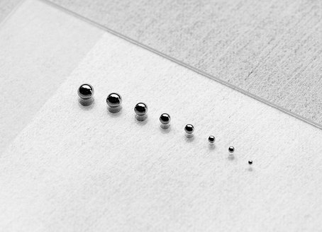
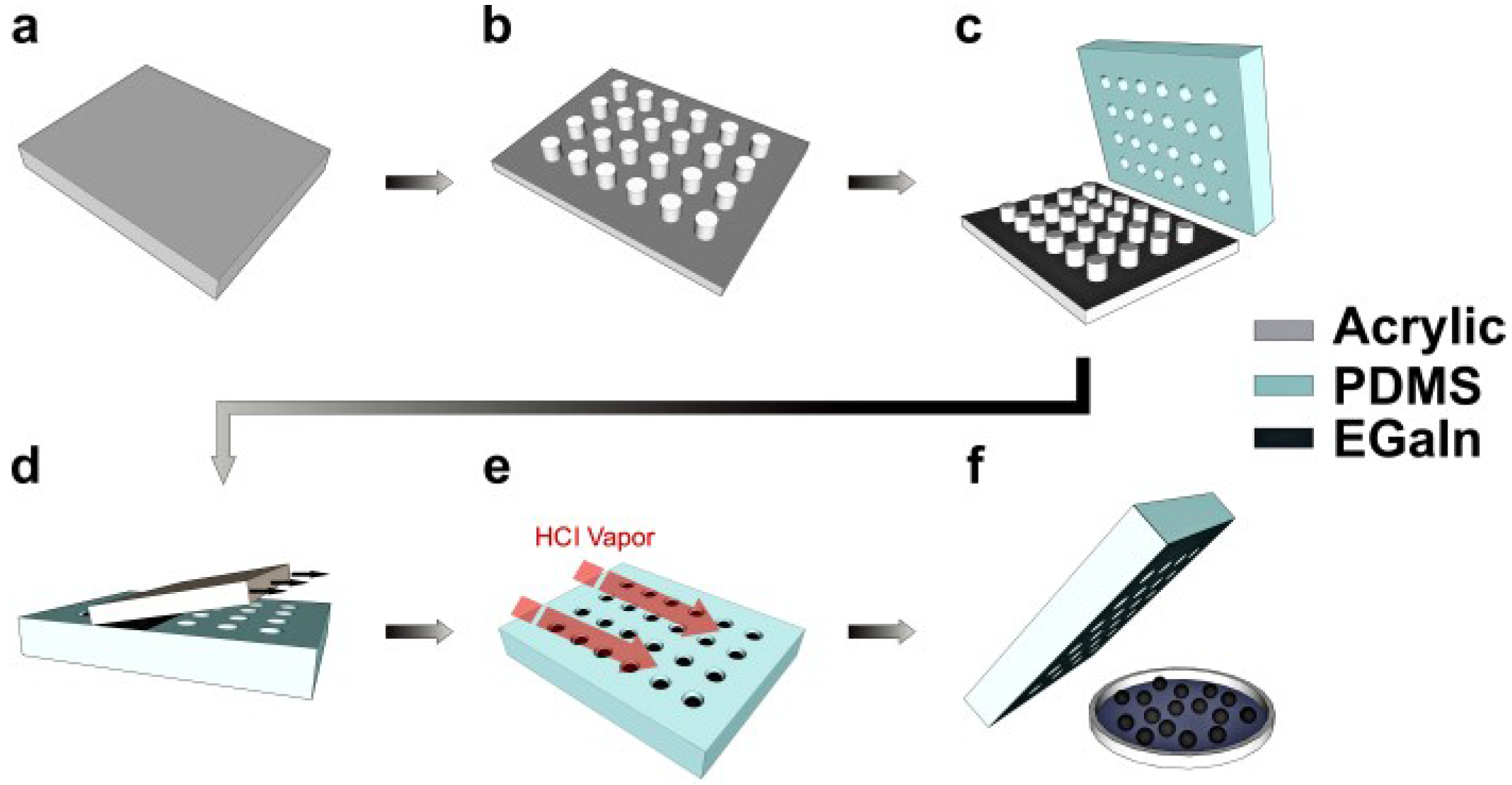
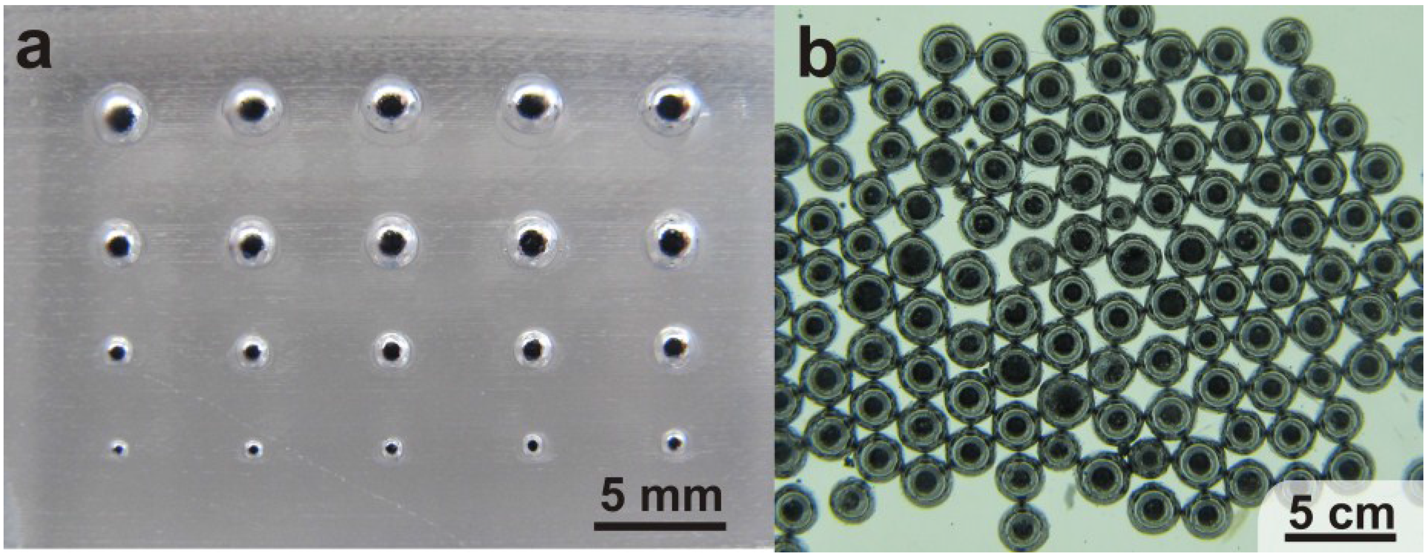
Figure 1 shows the steps to produce droplets. First, a laser writer (VLS3.50, Universal Laser Systems, Scottsdale, AZ, USA) patterns posts on a sheet of acrylic. Although there are many methods for patterning topography, we chose a laser writer, because of the ease of processing. The power and raster speed of the laser dictates the depth of the features according to a calibration curve (Figure S1 in the Supplementary Information). The laser limits the diameter of the posts to a ~200-μm diameter. Pouring and curing polydimethylsiloxane (PDMS, Dow Sylgard-184) over the acrylic mold produces a soft and flexible inverse replica featuring reservoirs. Spraying isopropanol over the PDMS mold prevents the metal from sticking to the flat (non-recessed) regions of the PDMS mold for reasons we do not completely understand, although the roughness of the PDMS in these regions may contribute to the lack of adhesion. Smearing the metal over the mold using the edge of a glass slide forces the liquid to fill into the voids and displaces the excess liquid metal. The oxide skin stabilizes the metal in the voids, such that it adopts a cylindrical-like shape. The oxide film that forms on gallium-based alloys is responsible for holding the metal in this non-equilibrium shape [52,53]. Hydrochloric acid vapor [54,55] from a cotton swab removes the EGaIn oxide skin (Figure 1e), causing the metal to bead up into a spherical shape within the mold, yet each drop stays within the void that defines its volume. Although the voids have a cylindrical shape, the resulting droplets are nearly perfect spheres, because of the high surface tension of the metal in the absence of the oxide. The beads can then be either harvested individually, poured out of the mold, transferred to another substrate or remain in the mold. The process is easy, quick and can be repeated many times using the same PDMS mold. Figure 2 shows EGaIn spheres sitting in a mold with reservoirs of decreasing size.
Figure 1.
Steps for producing EGaIn microspheres. (a,b) A laser writer patterns pillars on a sheet of acrylic. (c) PDMS molded against the acrylic creates an inverse replica. (d) After spraying isopropanol on the surface of the PDMS, another acrylic sheet forces EGaIn into the reservoirs. (e) EGaIn in the reservoir is exposed to HCl vapor to remove the oxide skin. (f) EGaIn spheres are released.

Figure 2.
(a) EGaIn spheres in a PDMS mold before removing them. (b) EGaIn drops collected and demolded into a petri dish.
Figure 2.
(a) EGaIn spheres in a PDMS mold before removing them. (b) EGaIn drops collected and demolded into a petri dish.

3. Results and Discussion
We sought to understand how well the method depicted in Figure 1 can control the diameter of the drops by varying the geometries of the reservoirs.
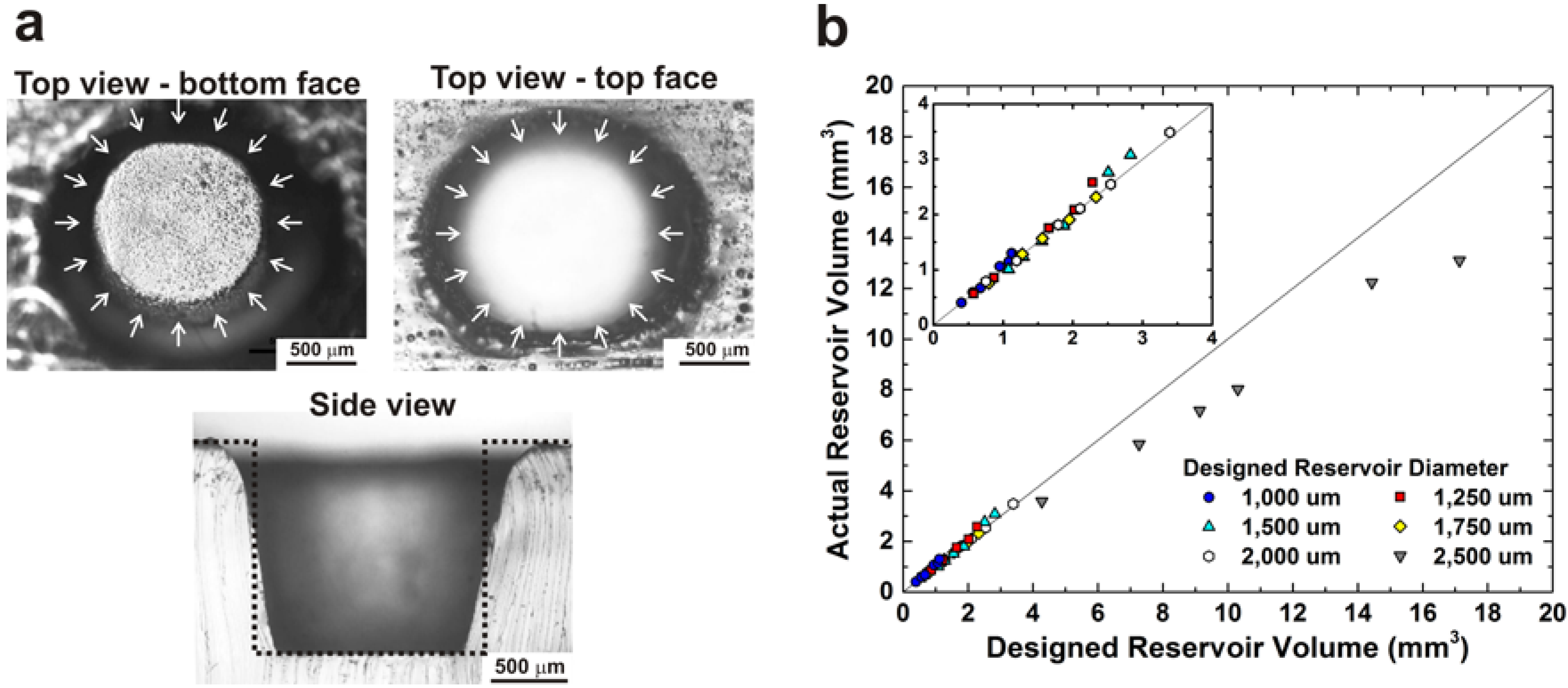
Although we programmed the laser cutter to create cylindrical reservoirs in acrylic, the laser produced cylindrical posts with tapered walls and an elliptical base. Figure 3a shows a side view and top views of the top and bottom surfaces of an empty PDMS reservoir. The arrows indicate the designed diameter of the cylinder. We measured the depth of the reservoirs by focusing on the top and then the bottom of the features using a calibrated optical microscope. This approach for estimating depth agreed with measurements done on larger features using a micrometer.
Figure 3.
(a) Micrographs of a representative empty reservoir (1500-μm designed diameter and 1420-μm thickness). The radial arrows and dotted lines represent the theoretical dimensions of the reservoir based on the design. The top view images are distinguished by the location of the focal plane of the microscope. The side view is obtained by cutting the PDMS with a razor blade. (b) A plot of the volume of the reservoir calculated based on the designed dimensions against the volume calculated from its actual dimensions. The inset plots only smaller volumes. The line, which has a slope = 1 and intercept = 0, represents an ideal agreement between the actual and designed reservoir volumes.

We compared the designed (theoretical) dimensions of the reservoirs with the actual measured volumes. Figure 3b indicates that reservoirs with volumes less than 4 mm3 show almost no deviation from the theoretical volume. The desired diameter lies between the actual diameters of the top and bottom sides of the reservoir, as indicated in the side view in Figure 3a. However, reservoirs greater than 4 mm3 have smaller volumes than the designed volumes. The use of an intense laser beam to penetrate deep into the acrylic sheet inadvertently reduces the area of the top surface of the post.
We varied the reservoir diameters (200, 1000, 1250, 1500, 1750 and 2500 μm) and depths (from 300 to 3000 μm) to form droplets with a variety of sizes. These sizes are easy to access using a laser cutter, which allows for rapid prototyping of molds.
The maximum diameter we produced is 3500 μm, although it is possible to make larger drops in principle. The molds produce droplets with diameters as small as ~200 μm. The resolution of the laser cutter provided the lower bound in our studies. Although we focus on droplets produced by molds fabricated by laser writing due to its simplicity, it is possible to apply the technique to molds produced by methods with higher resolution, including photolithography. As a proof of principle, we created droplets in molds with 100-μm diameters; however, the smearing technique used here could not force metal into reservoirs of 50 μm or smaller. This lower limit provides an opportunity to create features in the mold (e.g., microchannels) that will not fill with metal alongside reservoirs for the liquid metal microspheres. New techniques show that it is possible to imprint liquid metal into molds with features as small as 2 μm [56], which should be compatible with the principles of droplet formation shown here. As a point of reference, liquid spheres produced using other techniques typically have diameters ranging from 100 nm to 680 μm [37,44,50,57,58,59].
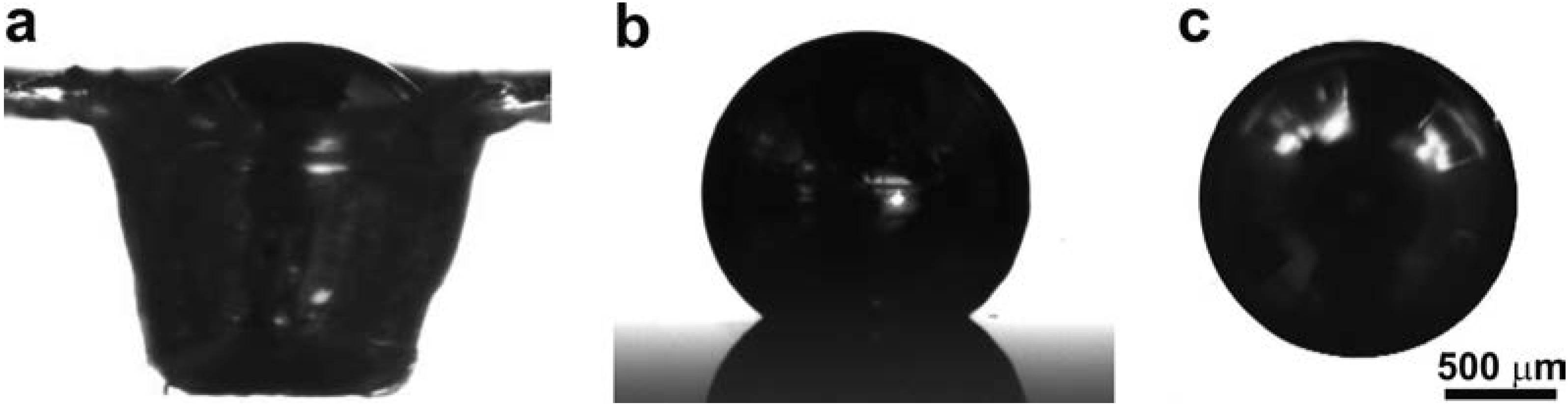
To characterize the size of the droplets, we took top-down microscope images of the droplets with a bright background and used ImageJ software to measure the diameter of the droplet, from which we calculated the volume. We also used a goniometer to take side-view images of the droplets and relied on the goniometer software to automatically calculate the volume of the droplet based on an axisymmetric projection of the droplet profile. The two methods gave very close values with a maximum discrepancy of 4.2%. We used the first method, since ImageJ can do batch image analysis in a single run. Figure 4 shows a side-view image of the reservoir filled with EGaIn, a top-down microscope image and a side view goniometer image of the same drop after releasing it from the reservoir.
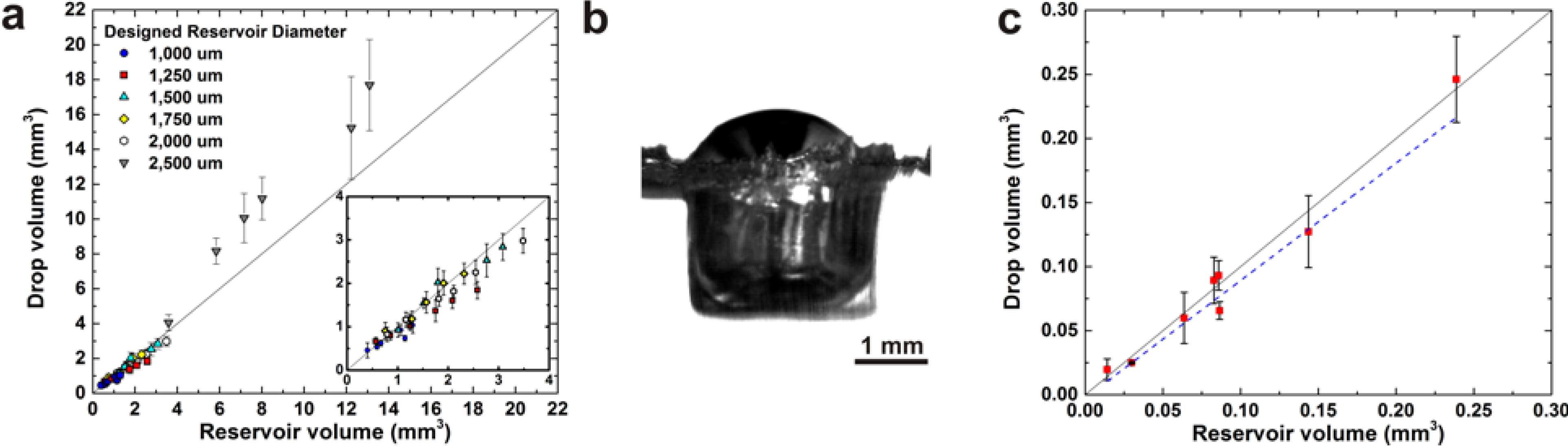
In principle, the volume of the liquid metal droplets should be equal to the volume of the reservoir if it fills the reservoir perfectly. Figure 5a shows the relation between the actual volume of the spheres and the volume of the reservoir. For reservoirs with a volume less than 4 mm3, the volume of liquid spheres agrees well with the reservoir volume, although it is sometimes slightly less than the reservoir volume. This deviation may result from under filling or EGaIn residue left inside the reservoir, which reduces the volume of the sphere. In contrast, droplets produced from larger reservoirs always have a volume larger than the volume of the reservoir. This deviation likely results from overfilling the reservoir with EGaIn, as shown in Figure 5b. Based on visual observations during spreading (cf. Figure 1d), the metal is more prone to flow under the spreader through the large reservoirs, which results in a spherical cap on top of the opening.
Figure 4.
(a) A side-view image of a reservoir filled with EGaIn; (b) a side-view goniometer image of the droplet after releasing it from the reservoir; and (c) a top-down microscope image of the same droplet.
Figure 4.
(a) A side-view image of a reservoir filled with EGaIn; (b) a side-view goniometer image of the droplet after releasing it from the reservoir; and (c) a top-down microscope image of the same droplet.

We quantified the effectiveness of the filling process by the filling factor, f, which is the ratio between the actual volume of the sphere (V) and the actual volume of the reservoir (Vo). Recall that the volume of the reservoirs matches the theoretical cylindrical volume for volumes less than or equal 4 mm3, so either geometry could be utilized interchangeably for Vo for that range. A filling factor of 1 represents a perfectly filled reservoir, whereas a value below 1 indicates an under-filled reservoir.
Figure 5.
(a) Graphical relation between the volume of EGaIn spheres and the actual volume of the reservoir. The lines of slope = 1 and intercept = 0 guide the eye for an ideal agreement between the reservoir and drop volume. (b) A side view of a reservoir overfilled with EGaIn, which appears dark due to the backlighting. (c) Graphical relation for the smallest spheres. The blue dotted lines in the inset graph in plot (a) and in plot (c) graph are the best linear fit for the data, whose slope is the filling factor.

We sought to calculate the value of the filling factor for the droplets with volumes smaller than 4 mm3. We limit our analysis to these volumes due to the deviations that occur at larger volumes due to filling error. We did an additional analysis for the droplets with volumes from 0.01 to 0.25 mm3 due to their importance in microdevices and solder bumps.
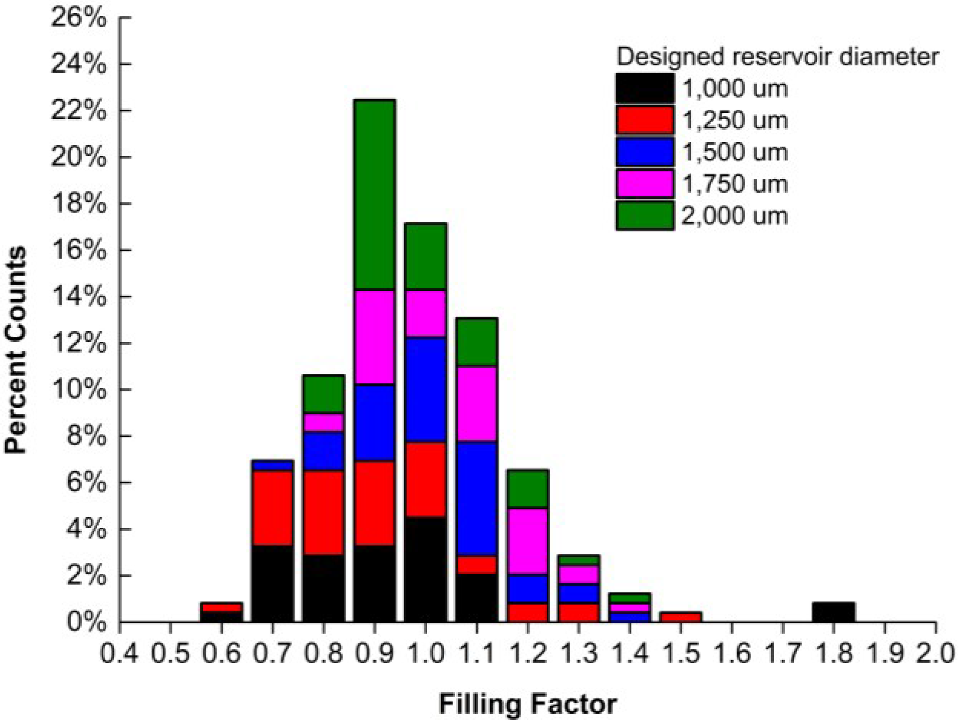
We estimate the filling factor in two ways. First, the slope of the linear fit of the points in Figure 5a gives a value of f = 0.96, and the slope of the linear fit of Figure 5c gives a value of f = 0.975. These similar values suggest that the reservoirs typically fill uniformly and without major voids. Figure 6 plots the distribution of filling factors. Excluding the three largest fill factors (from a data set of 203 droplets), the data had a normal distribution as evidenced by the Shapiro–Wilk test probability value of 0.14 (>0.05) and standard deviation of 0.18. This result suggests that most of the fill factor data is randomly distributed about a mean value of 0.915, which is slightly lower than the value obtained from fitting the points in Figure 5a. Taken in sum, the results suggest that, on average, the reservoirs fill uniformly, but there is some distribution of sizes due to the imprecise spreading method with which the metal distributes into the reservoirs. We also evaluated (not shown) the effect of aspect ratio (reservoir height to diameter ratio) on filling and found that aspect ratios greater than 0.6 did not fill well and were not included in the study; however, lower aspect ratios filled well, including the lowest one we tried, 0.12. The dependency on aspect ratio suggests that the meniscus of the metal may need to touch the bottom of the reservoir to facilitate filling.
Figure 6.
The percent counts of the filling factor of reservoirs with EGaIn.

Figure 7.
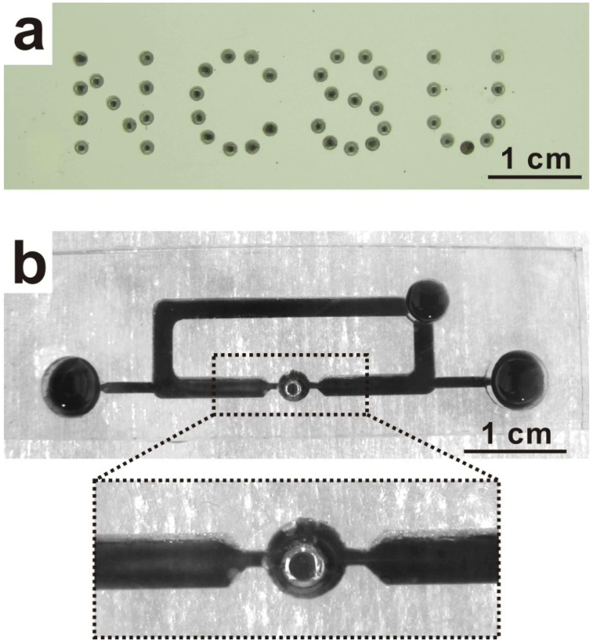
(a) EGaIn spheres embedded completely in PDMS; (b) a liquid metal drop placed in a liquid metal pump using the molding technique.
Figure 7.
(a) EGaIn spheres embedded completely in PDMS; (b) a liquid metal drop placed in a liquid metal pump using the molding technique.

In addition to harvesting droplets via demolding (cf. Figure 4), EGaIn spheres or microcylinders (i.e., the shape of the metal before removing the oxide) can be embedded in polymers in any desired pattern. After forming droplets in the reservoirs, we poured more polymer over the droplets to seal and enclose the spheres in the mold instead of pushing them out. Figure 7a shows EGaIn drops embedded in a PDMS matrix. Likewise, it is possible to encase the metal features into microdevices and microchannels. Figure 7b shows a liquid metal drop formed by spreading the metal into a reservoir connected to a microchannel. A planar layer of polymer seals the device. After removing the oxide, the metal beads up to create a droplet inside the microchannel. This geometry mimics that utilized previously [22] to create a liquid metal pump, and in principle, it could be utilized for other applications, including energy harvesting by reverse electrowetting [19] and micromechanical switches [60].
In principle, it may be possible to transfer the droplets from the mold to arbitrary substrates while maintaining lateral spacing between droplets. In practice, we found that in the absence of the oxide skin, the metal droplets roll around on the target substrate and, therefore, lose their order outside of the mold. It may be possible to utilize recessed wells on the target substrate, tacky coatings or wetting substrates (e.g., other metal films) to prevent the metal from moving laterally during transfer.
4. Conclusions
This paper describes a simple method to produce and pattern spheres of EGaIn in molds. The process forces EGaIn into reservoirs that define the size and location of the final droplets. The formation of a surface oxide on EGaIn allows it to conform within the reservoirs during the spreading process and the removal of the oxide by exposure to acid causes the metal to bead up into droplets on demand within the molded features. Although we focus on EGaIn, this technique can likely be applied to any liquid metal alloy containing gallium and, in principle, could be extended to molten metals at elevated temperatures. The volume of the spheres can be controlled easily by changing the dimensions of the reservoirs. This technique can be used for producing many spheres in parallel with any desired two-dimensional spatial arrangement. The resulting EGaIn spheres can be collected, embedded in other materials, such as polymer, or encased in microdevices. In principle, this technique should be compatible with other conventional planar microfabrication techniques. On average, the droplets reproduce the geometry of the molds faithfully. The droplets formed by this technique are not perfectly monodisperse, but form without the need for any stabilizing surfactant, due to their physical isolation. With a more automated spreading process, the standard deviation should improve. It may be possible to scale up the production process by using larger substrates. This technique offers a fast and easy method for preparing liquid metal spheres with a wide range of volumes.
Acknowledgments
This work was supported by NSF CAREER Award Number 0954321. The authors thank David Dickey for the statistical normal distribution analysis and Rifat Hassan for the help she offered.
Author Contributions
Mohammed Mohammed: sample preparations, data analysis and writing the manuscript.
Alexis Xenakis: developed the process.
Michael D. Dickey: supervision of the first and second authors and writing the manuscript.
Conflicts of Interest
The authors declare no conflict of interest.
References
- French, S.J.; Saunders, D.J.; Ingle, G.W. The system gallium-indium. J. Phys. Chem. 1937, 42, 265–274. [Google Scholar]
- Zrnic, D.; Swatik, D.S. On the resistivity and surface tension of the eutectic alloy of gallium and indium. J. Common Met. 1969, 18, 67–68. [Google Scholar]
- So, J.; Thelen, J.; Qusba, A.; Hayes, G.J.; Lazzi, G.; Dickey, M.D. Reversibly deformable and mechanically tunable fluidic antennas. Adv. Funct. Mater. 2009, 19, 3632–3637. [Google Scholar]
- Cheng, S.; Rydberg, A.; Hjort, K.; Wu, Z. Liquid metal stretchable unbalanced loop antenna. Appl. Phys. Lett. 2009, 94, 144103:1–144103:3. [Google Scholar]
- Kubo, M.; Li, X.; Kim, C.; Hashimoto, M.; Wiley, B.J.; Ham, D.; Whitesides, G.M. Stretchable Microfluidic Radiofrequency Antennas. Adv. Mater. 2010, 22, 2749–2752. [Google Scholar]
- Khan, M.R.; Hayes, G.J.; So, J.-H.; Lazzi, G.; Dickey, M.D. A frequency shifting liquid metal antenna with pressure responsiveness. Appl. Phys. Lett. 2011, 99, 013501:1–013501:3. [Google Scholar]
- Palleau, E.; Reece, S.; Desai, S.C.; Smith, M.E.; Dickey, M.D. Self-healing stretchable wires for reconfigurable circuit wiring and 3D microfluidics. Adv. Mater. 2013, 25, 1589–1592. [Google Scholar]
- Blaiszik, B.J.; Kramer, S.L.B.; Grady, M.E.; McIlroy, D.A.; Moore, J.S.; Sottos, N.R.; White, S.R. Autonomic restoration of electrical conductivity. Adv. Mater. 2012, 24, 398–401. [Google Scholar]
- Zhu, S.; So, J.-H.; Mays, R.L.; Desai, S.; Barnes, W.R.; Pourdeyhimi, B.; Dickey, M.D. Ultrastretchable fibers with metallic conductivity using a liquid metal alloy core. Adv. Fun. Mat. 2013, 23, 2308–2314. [Google Scholar]
- Kim, H.-J.; Son, C.; Ziaie, B. A multiaxial stretchable interconnect using liquid-alloy-filled elastomeric microchannels. Appl. Phys. Lett. 2008, 92, 011904:1–011904:3. [Google Scholar]
- Park, J.; Wang, S.; Li, M.; Ahn, C.; Hyun, J.K.; Kim, D.S.; Kim, D.K.; Rogers, J.A.; Huang, Y.; Jeon, S. Three-dimensional nanonetworks for giant stretchability in dielectrics and conductors. Nat. Commun. 2012, 3, 916. [Google Scholar]
- Zhang, Y.; Zhao, Z.; Fracasso, D.; Chiechi, R.C. Bottom-up molecular tunneling junctions formed by self-assembly. Isr. J. Chem. 2014, 54, 513–533. [Google Scholar]
- So, J.-H.; Dickey, M.D. Inherently aligned microfluidic electrodes composed of liquid metal. Lab Chip 2011, 11, 905–911. [Google Scholar]
- Cheng, S.; Wu, Z. Microfluidic electronics. Lab. Chip 2012, 12, 2782–2791. [Google Scholar]
- Majidi, C.; Kramer, R.; Wood, R.J. A non-differential elastomer curvature sensor for softer-than-skin electronics. Smart Mater. Struct. 2011, 20, 105017. [Google Scholar]
- Park, Y.-L.; Tepayotl-Ramirez, D.; Wood, R.J.; Majidi, C. Influence of cross-sectional geometry on the sensitivity and hysteresis of liquid-phase electronic pressure sensors. Appl. Phys. Lett. 2012, 101, 191904. [Google Scholar]
- Dickey, M.D.; Chiechi, R.C.; Larsen, R.J.; Weiss, E.A.; Weitz, D.A.; Whitesides, G.M. Eutectic gallium-indium (EGaIn): A liquid metal alloy for the formation of stable structures in microchannels at room temperature. Adv. Funct. Mater. 2008, 18, 1097–1104. [Google Scholar]
- Ladd, C.; So, J.-H.; Muth, J.; Dickey, M.D. 3D Printing of free standing liquid metal microstructures. Adv. Mater. 2013, 25, 5081–5085. [Google Scholar]
- Krupenkin, T.; Taylor, J.A. Reverse electrowetting as a new approach to high-power energy harvesting. Nat. Commun. 2011, 2, 448. [Google Scholar]
- So, J.-H.; Koo, H.-J.; Dickey, M.D.; Velev, O.D. Ionic current rectification in soft-matter diodes with liquid-metal electrodes. Adv. Funct. Mater. 2012, 22, 625–631. [Google Scholar]
- Yun, K.-S.; Cho, I.-J.; Bu, J.-U.; Kim, C.-J.; Yoon, E. A surface-tension driven micropump for low-voltage and low-power operations. J. Microelectromech. Syst. 2002, 11, 454–461. [Google Scholar]
- Tang, S.-Y.; Khoshmanesh, K.; Sivan, V.; Petersen, P.; O’Mullane, A.P.; Abbott, D.; Mitchell, A.; Kalantar-zadeh, K. Liquid metal enabled pump. Proc. Natl. Acad. Sci. USA 2014, 111, 3304–3309. [Google Scholar]
- Kim, H.-J.; Zhang, M.; Ziaie, B. A biaxially stretchable interconnect with liquid alloy joints on flexible substrate. In TRANSDUCERS 2007. International Solid-State Sensors, Actuators and Microsystems Conference, 2007; IEEE: New York, NY, USA, 2007; pp. 1597–1600. [Google Scholar]
- Sivan, V.; Tang, S.-Y.; O’Mullane, A.P.; Petersen, P.; Eshtiaghi, N.; Kalantar-zadeh, K.; Mitchell, A. Liquid metal marbles. Adv. Funct. Mater. 2013, 23, 144–152. [Google Scholar]
- Sen, P.; Kim, C.-J. A fast liquid-metal droplet microswitch using ewod-driven contact-line sliding. J. Microelectromech. Syst. 2009, 18, 174–185. [Google Scholar]
- Simon, J.; Saffer, S.; Kim, J.Y. A liquid-filled microrelay with a moving mercury microdrop. J. Microelectromech. Syst. 1997, 6, 208–216. [Google Scholar]
- Hayes, D.J.; Wallace, D.B.; Cox, W.R. MicroJet printing of solder and polymers for multi-chip modules and chip-scale packages. In Proceedings-SPIE the International Society for Optical Engineering; SPIE: Bellingham WA, USA, 1999; pp. 242–247. [Google Scholar]
- Tong, H.-M.; Lai, Y.-S.; Wong, C.P. Advanced Flip Chip Packaging, 2013 edition; Springer: New York, NY, USA; London, UK, 2013. [Google Scholar]
- Van der Graaf, S.; Schroën, C.G.P.H.; Boom, R.M. Preparation of double emulsions by membrane emulsification—A review. J. Membr. Sci. 2005, 251, 7–15. [Google Scholar]
- Vladisavljević, G.T.; Williams, R.A. Recent developments in manufacturing emulsions and particulate products using membranes. Adv. Colloid Interface Sci. 2005, 113, 1–20. [Google Scholar] [Green Version]
- Kobayashi, I.; Uemura, K.; Nakajima, M. Formulation of monodisperse emulsions using submicron-channel arrays. Colloids Surf. Physicochem. Eng. Asp. 2007, 296, 285–289. [Google Scholar]
- Teh, S.-Y.; Lin, R.; Hung, L.-H.; Lee, A.P. Droplet microfluidics. Lab Chip 2008, 8, 198–220. [Google Scholar]
- Bon, S.A.F.; Mookhoek, S.D.; Colver, P.J.; Fischer, H.R.; van der Zwaag, S. Route to stable non-spherical emulsion droplets. Eur. Polym. J. 2007, 43, 4839–4842. [Google Scholar]
- Maa, Y.-F.; Hsu, C.C. Performance of sonication and microfluidization for liquid–liquid emulsification. Pharm. Dev. Technol. 1999, 4, 233–240. [Google Scholar]
- Yu, Y.; Wang, Q.; Yi, L.; Liu, J. Channelless fabrication for large-scale preparation of room temperature liquid metal droplets. Adv. Eng. Mater. 2014, 16, 255–262. [Google Scholar]
- Kobayashi, I.; Nakajima, M.; Mukataka, S. Preparation characteristics of oil-in-water emulsions using differently charged surfactants in straight-through microchannel emulsification. Colloids Surf. Physicochem. Eng. Asp. 2003, 229, 33–41. [Google Scholar]
- Sugiura, S.; Nakajima, M.; Yamamoto, K.; Iwamoto, S.; Oda, T.; Satake, M.; Seki, M. Preparation characteristics of water-in-oil-in-water multiple emulsions using microchannel emulsification. J. Colloid Interface Sci. 2004, 270, 221–228. [Google Scholar]
- Zhao, C.-X.; Middelberg, A.P.J. Two-phase microfluidic flows. Chem. Eng. Sci. 2011, 66, 1394–1411. [Google Scholar]
- Christopher, G.F.; Anna, S.L. Microfluidic methods for generating continuous droplet streams. J. Phys. Appl. Phys. 2007, 40, R319. [Google Scholar]
- Gu, H.; Duits, M.H.G.; Mugele, F. Droplets formation and merging in two-phase flow microfluidics. Int. J. Mol. Sci. 2011, 12, 2572–2597. [Google Scholar]
- Cramer, C.; Fischer, P.; Windhab, E.J. Drop formation in a co-flowing ambient fluid. Chem. Eng. Sci. 2004, 59, 3045–3058. [Google Scholar]
- Nisisako, T.; Torii, T.; Takahashi, T.; Takizawa, Y. Synthesis of monodisperse bicolored janus particles with electrical anisotropy using a microfluidic co-flow system. Adv. Mater. 2006, 18, 1152–1156. [Google Scholar]
- Thorsen, T.; Roberts, R.W.; Arnold, F.H.; Quake, S.R. Dynamic pattern formation in a vesicle-generating microfluidic device. Phys. Rev. Lett. 2001, 86, 4163–4166. [Google Scholar]
- Yang, C.-H.; Huang, K.-S.; Lin, P.-W.; Lin, Y.-C. Using a cross-flow microfluidic chip and external crosslinking reaction for monodisperse TPP-chitosan microparticles. Sens. Actuators B Chem. 2007, 124, 510–516. [Google Scholar]
- Fidalgo, L.M.; Whyte, G.; Bratton, D.; Kaminski, C.F.; Abell, C.; Huck, W.T.S. From microdroplets to microfluidics: Selective emulsion separation in microfluidic devices. Angew. Chem. Int. Ed. 2008, 47, 2042–2045. [Google Scholar]
- Anna, S.L.; Bontoux, N.; Stone, H.A. Formation of dispersions using “flow focusing” in microchannels. Appl. Phys. Lett. 2003, 82, 364–366. [Google Scholar]
- Friedman, H.; Reich, S.; Popovitz-Biro, R.; von Huth, P.; Halevy, I.; Koltypin, Y.; Gedanken, A.; Porat, Z. Micro- and nano-spheres of low melting point metals and alloys, formed by ultrasonic cavitation. Ultrason. Sonochem. 2013, 20, 432–444. [Google Scholar]
- Han, Z.H.; Yang, B.; Qi, Y.; Cumings, J. Synthesis of low-melting-point metallic nanoparticles with an ultrasonic nanoemulsion method. Ultrasonics 2011, 51, 485–488. [Google Scholar]
- Hohman, J.N.; Kim, M.; Wadsworth, G.A.; Bednar, H.R.; Jiang, J.; LeThai, M.A.; Weiss, P.S. Directing substrate morphology via self-assembly: Ligand-mediated scission of gallium–indium microspheres to the nanoscale. Nano Lett. 2011, 11, 5104–5110. [Google Scholar]
- Thelen, J.; Dickey, M.D.; Ward, T. A study of the production and reversible stability of EGaIn liquid metal microspheres using flow focusing. Lab. Chip 2012, 12, 3961–3967. [Google Scholar]
- Hutter, T.; Bauer, W.-A.C.; Elliott, S.R.; Huck, W.T.S. Formation of spherical and non-spherical eutectic gallium-indium liquid-metal microdroplets in microfluidic channels at room temperature. Adv. Funct. Mater. 2012, 22, 2624–2631. [Google Scholar]
- Scharmann, F.; Cherkashinin, G.; Breternitz, V.; Knedlik, C.; Hartung, G.; Weber, T.; Schaefer, J.A. Viscosity effect on GaInSn studied by XPS. Surf. Interface Anal. 2004, 36, 981–985. [Google Scholar]
- Kim, D.; Lee, D.-W.; Choi, W.; Lee, J.-B. A super-lyophobic 3-D PDMS channel as a novel microfluidic platform to manipulate oxidized galinstan. J. Microelectromech. Syst. 2013, 22, 1267–1275. [Google Scholar]
- Kim, D.; Thissen, P.; Viner, G.; Lee, D.-W.; Choi, W.; Chabal, Y.J.; Lee, J.-B. Recovery of nonwetting characteristics by surface modification of gallium-based liquid metal droplets using hydrochloric acid vapor. ACS Appl. Mater. Interfaces 2013, 5, 179–185. [Google Scholar]
- Doudrick, K.; Liu, S.; Mutunga, E.M.; Klein, K.L.; Damle, V.; Varanasi, K.K.; Rykaczewski, K. Different shades of oxide: From nanoscale wetting mechanisms to contact printing of gallium-based liquid metals. Langmuir 2014, 30, 6867–6877. [Google Scholar]
- Gozen, B.A.; Tabatabai, A.; Ozdoganlar, O.B.; Majidi, C. High-density soft-matter electronics with micron-scale line width. Adv. Mater. 2014, 26, 5211–5216. [Google Scholar]
- Dalmoro, A.; Barba, A.A.; d’Amore, M. Analysis of size correlations for microdroplets produced by ultrasonic atomization. Sci. World J. 2013, 2013, 482910. [Google Scholar]
- Nisisako, T.; Torii, T. Microfluidic large-scale integration on a chip for mass production of monodisperse droplets and particles. Lab Chip 2008, 8, 287–293. [Google Scholar]
- Wang, Y.; Xia, Y. Bottom-up and top-down approaches to the synthesis of monodispersed spherical colloids of low melting-point metals. Nano Lett. 2004, 4, 2047–2050. [Google Scholar]
- Kim, J.; Shen, W.; Latorre, L.; Kim, C.-J. A micromechanical switch with electrostatically driven liquid-metal droplet. Sens. Actuators Phys. 2002, 97–98, 672–679. [Google Scholar]
© 2014 by the authors; licensee MDPI, Basel, Switzerland. This article is an open access article distributed under the terms and conditions of the Creative Commons Attribution license (http://creativecommons.org/licenses/by/4.0/).
Share and Cite
MDPI and ACS Style
Mohammed, M.G.; Xenakis, A.; Dickey, M.D. Production of Liquid Metal Spheres by Molding. Metals 2014, 4, 465-476. https://doi.org/10.3390/met4040465
AMA Style
Mohammed MG, Xenakis A, Dickey MD. Production of Liquid Metal Spheres by Molding. Metals. 2014; 4(4):465-476. https://doi.org/10.3390/met4040465
Chicago/Turabian StyleMohammed, Mohammed G., Alexis Xenakis, and Michael D. Dickey. 2014. "Production of Liquid Metal Spheres by Molding" Metals 4, no. 4: 465-476. https://doi.org/10.3390/met4040465