Grain Refinement and Deformation Mechanisms in Room Temperature Severe Plastic Deformed Mg-AZ31

 ,
,
Abstract
: A Ti-AZ31 composite was severely plastically deformed by rotary swaging at room temperature up to a logarithmic deformation strain of 2.98. A value far beyond the forming limit of pure AZ31 when being equivalently deformed. It is observed, that the microstructure evolution in Mg-AZ31 is strongly influenced by twinning. At low strains the {1̄011} ⟨101̄2⟩ and the {1̄012} ⟨101̄1⟩ twin systems lead to fragmentation of the initial grains. Inside the primary twins, grain refinement takes place by dynamic recrystallization, dynamic recovery and twinning. These mechanisms lead to a final grain size of ≈ 1 μm, while a strong centered ring fibre texture is evolved.1. Introduction
As fossil resources decrease rapidly, it is essential to use such resources as efficiently as possible. This effort, amongst others, creates a high demand for strong and light weight materials, for e.g., mobile applications. Magnesium alloys are quite promising candidates due to their high specific strength. However, their application is limited as metal forming is not an appropriate possibility to generate end-shape-geometries due to the very low ductility at room temperature. Buchmann et al.. and Becker et al.. reported that the elongation to failure of AZ31 is about η ≈ 0.1 [1,2]. Due to the hexagonal close packed structure, with a nearly ideal c/a ratio of 1.633, the Taylor requirement for the deformation of polycrystalline materials is not fulfilled at room temperature, hence ductility is limited.
Recent research on the formability of Mg alloys involves the activation of alternative deformation mechanisms that have been reported for ultra-fine-grained (UFG) or even nanometer-scaled materials [3]. Being introduced by Gleiter [4], grain boundary sliding and/or grain rotation represent these deformation mechanisms. As for as materials being ultra-fine-grained these mechanisms are believed to be activated in any type of metallic material. Consequently, the aim of increasing the formability of Mg alloys is combined with severe plastic deformation, i.e., a common technique to refine the microstructure to the ultra-fine-grained region. Indeed, recent studies revealed that it is possible to increase strength and ductility at the same time, when processing metallic materials by SPD [5]. The importance of a SPD method for magnesium corresponds to an improvement of mechanical properties by creating an ultra-fine-grained Mg. There are some researches dealing with severe plastic deformed AZ31 and Mg [6–11]. These outstanding mechanical properties are commonly linked to the formation of an ultra-fine-grained microstructure caused by SPD [12,13]. Bonarski et al.. and Furukawa et al.. reported, that magnesium exhibits an asymmetric grain size distribution, when being deformed at a low deformation strain. In contrast, a homogeneous microstructure can be achieved when a high deformation strain has been applied [12,13]. This underlies the requirement of large deformation strains or even the need for the application of SPD processes to obtain Mg alloys with a large formability. Although the grain size seems to be the new parameter determining the activation of additional deformation mechanisms and thus for enhancing the ductility, the situation reveals not that simple. It has also been shown in literature, that grain refinement is strongly influenced by twinning, dynamic recrystallization (DRX) and recovery [6,14]. These mechanisms are regarded as the dominating factors for the evolution of the microstructure of AZ31 deformed to high strains at room temperature as will be shown in the following.
This study shows in detail the microstructural evolution of Mg AZ31 being severely deformed at room temperature to a logarithmic deformation strain of 2.98. The uncommon technique of rotary swaging is used for deformation and might a good opportunity to deform magnesium alloys to high deformation strains. The microstructure of the Mg AZ31 alloy has been evaluated for various deformation strains. This also implies the investigation of the mechanisms causing the grain refinement. For this purpose orientation imaging microscopy was performed at various strain levels in order to examine: (i) grain size and its distribution; (ii) texture; (iii) grain boundary misorientation and (iv) twinning behavior.
2. Experimental Section
2.1. Processing
To achieve a high degree of deformation in Mg AZ31, the material was co-deformed within a composite using a four jaw rotary swaging machine. This composite consists of a titanium grade 1 tube (Øinside = 20 mm; Øoutside = 24 mm) filled by a Mg AZ31 rod. This composite was severely plastically deformed by rotary swaging from 24 to 5.4 mm in diameter, which corresponds to a log. deformation strain of 2.98.
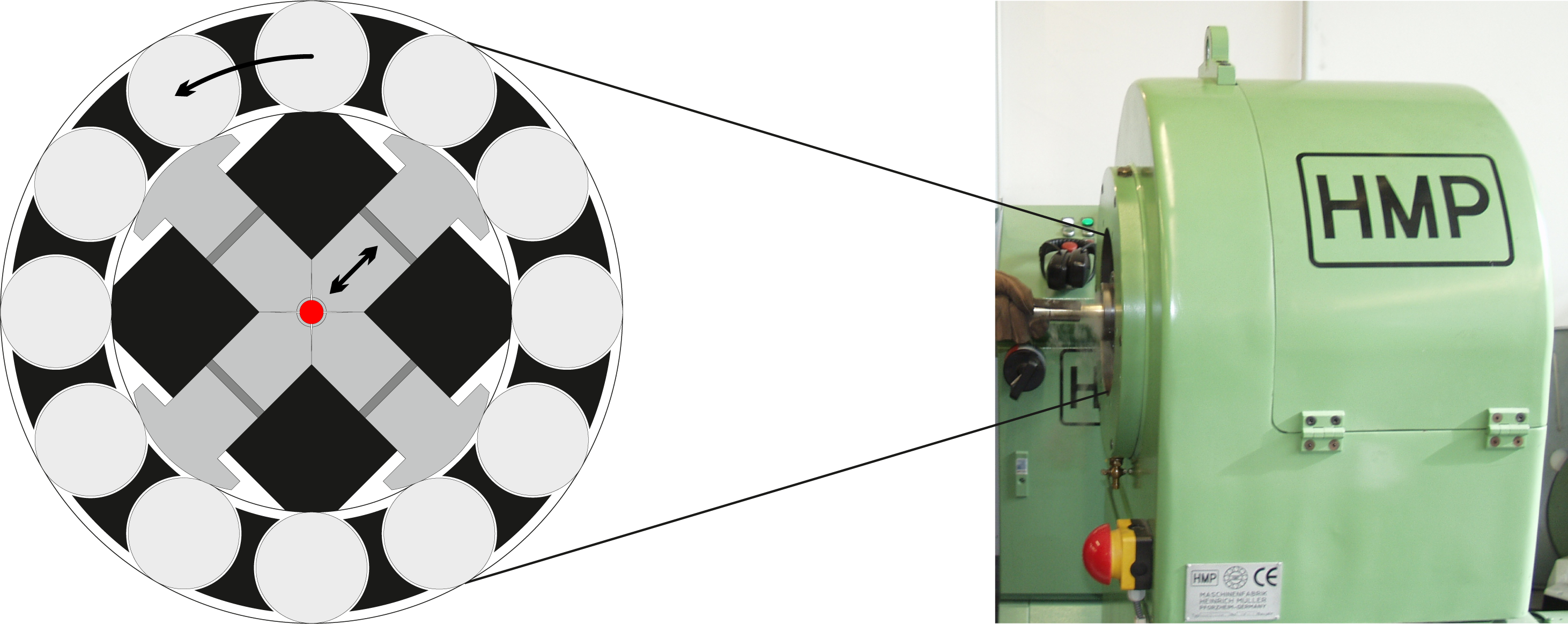
Rotary swaging is a uncommon SPD technique and should be explained in more detail [15,16]. Therefore, a rotary swaging machine is shown in Figure 1 and a sketch of the working method is given on the left side. The machine used for deformation, contains four jaws. These jaws swage the workpiece, which moved through the centre. In this way, the diameter of the composite will be incrementally reduced. A cross sectional area reduction of 20% per pass was applied and after each pass the material was immediately cooled in water. There are a limited number of works dealing with severe plastic deformed Mg at room temperature [17,18]. There are some advantages of rotary swaging. On the one hand, it is possible to deform the whole composite, while the materials are reshaped into semi-finished products like rods or wires.
2.2. Metallographic Sample Preparation
The wires were prepared in cross section for scanning electron microscopy (SEM) investigations. The sample preparation was done by mechanical grinding up to 4000 SiC paper followed by polishing using a lubricant containing 50 nm colloidal SiO2 particles. Furthermore samples were etched with a solution containing 75 vol.% H2O 23 vol.% H2SO4 and 2 vol.% HF for 30 s and afterwards they were polished again. Finally, samples were treated by an Ar-ion beam for 1 h using low incident beam angles of 5°,an acceleration voltage of 5 kV and anode current of 2 mA. This treatment was necessary to eliminate the Beilby’s layer and to enable the electron backscatter diffraction (EBSD) measurement.
2.3. Scanning Electron Microscopy
The cross sectional areas of the wires were investigated by scanning electron microscopy (SEM). For this purpose a Zeiss LEO 1530 SEM was used for EBSD measurement operating at 10 kV acceleration voltage. EBSD analysis was carried out with a working distance of 15 mm and a general step size of 80 nm, while the samples were tilted by 70°. Only in the case of initial state and log. strain of 0.54 a step size of 3 μm and 0.2 μm were chosen. Due to the severely deformed material, the indexing rate was low. For this reason a two step indexing procedure was applied. Four to five Kikuchi bands were used for calculating the orientation of a data point. If the Kikuchi pattern quality was too bad for indexing, the pattern was saved. Afterwards, these poor quality patterns were re-analysed using only three to four Kikuchi bands for indexing. By this way, the indexing rate could be improved from 60%–70% to 85%–90%. Only little noise had been introduced using this procedure. However, this was carefully observed and mainly excluded afterwards using a software filter implemented in the HKL CHANNEL5 software. Finally, the maps were wiped out of zero solutions, which were surrounded by at least five indexed points. These former zero solutions were then regarded to have the mean orientation of the surrounding points. If the misorientation of two nearest measurement points were larger than (i) 3° or (ii) 15° these points were assigned to different grains. These criteria provided a minimal misorientation angle between two data points, to define a grain boundary. Hence, it was possible to evaluate the contribution of LAGB and HAGB to the microstructure evolution by using these criteria.
3. Results and Discussion
3.1. Grain Size Evolution
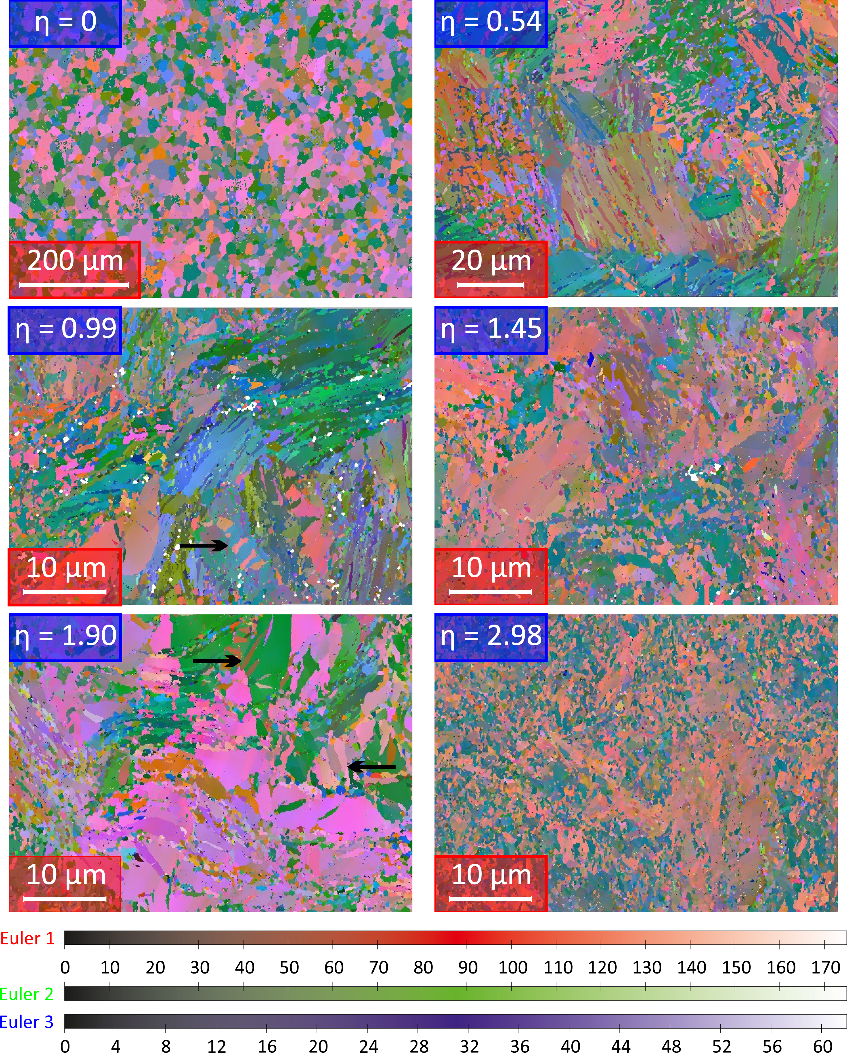
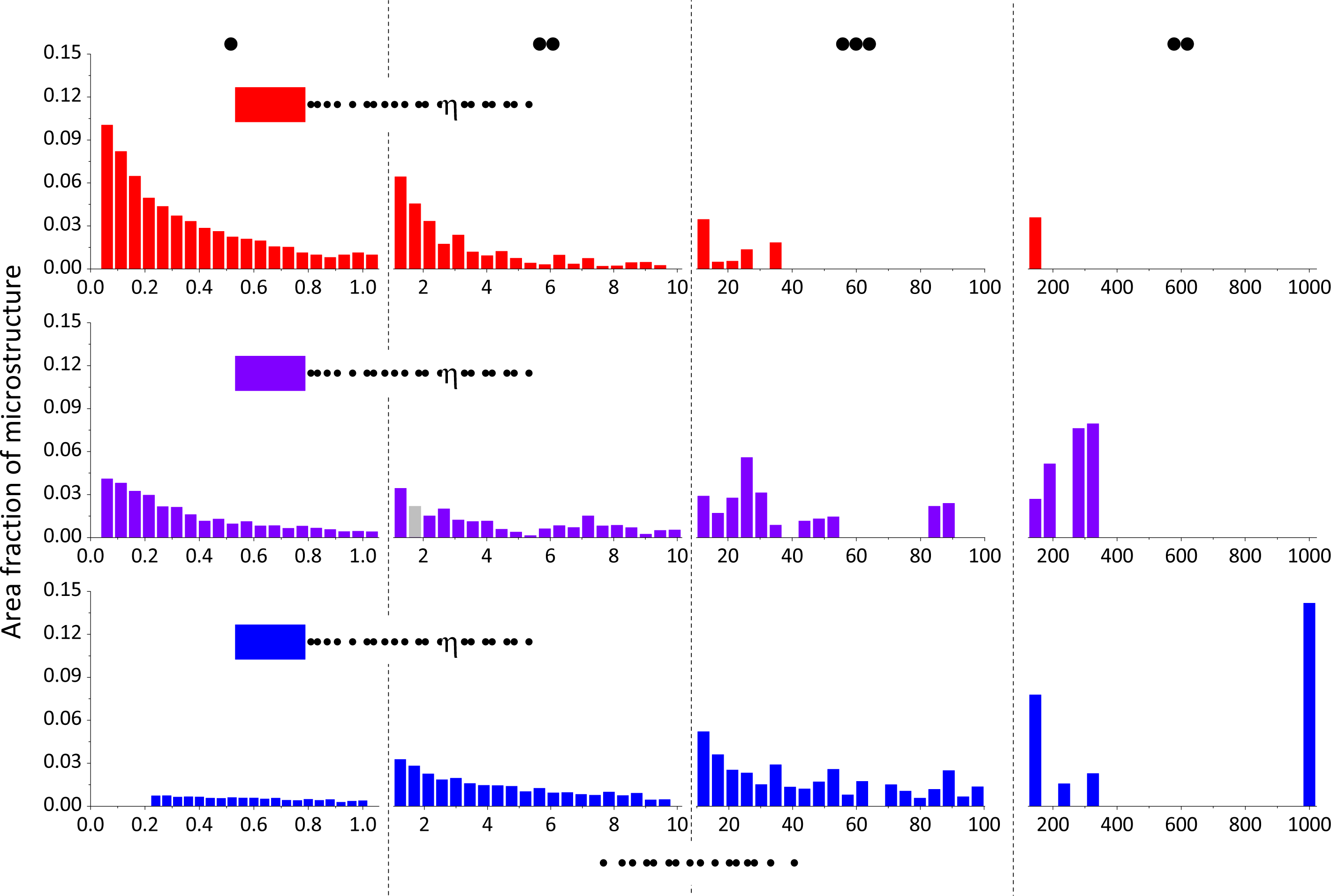
The EBSD maps were taken from the wire center, since no significant difference of the microstructure near the center and the outer limit of AZ31 could be observed. In Figure 2 EBSD maps of the microstructure are shown in Euler angle color code at different strain levels. The non-deformed state exhibits an equiaxed microstructure and a grain size above 20 μm. With starting deformation, fine grains are formed, surrounding coarser grains. Young et al.. and Biswas et al.. reported similar observations at low strains [11,19]. As can be seen in Figure 2, small grains are already formed within initial grains at a true strain of 0.54 and also some twins are observed. Please note the different scale bar for EBSD maps of η = 0 and η = 0.54 compared to the other images. Progressive deformation leads to a grain refinement shown by images of η = 0.99 to η = 2.98. Thereby, it becomes difficult to identify twins in the present EBSD maps at high deformation strains. At η = 0.99 and η = 1.90 some twins are exemplary highlighted. Twinning and grain refinement will be discussed later and the grain diameter will be calculated from equivalent circle area. After straining to η = 2.98, the microstructure becomes more homogeneous and the grain size shrinks to less than 1 μm as we will show in the following. This is in good agreement with Young et al.. and Biswas et al.. who showed, that high strain is necessary to obtain a small range of grain size distribution [11,19]. The quantitative evaluation of the grain size distribution at η = 0.54; 1.9 and 2.98 are presented in Figure 3. Herein, the area fraction of a certain grain class is shown with respect to its grain area. The area fractions of grains within one grain class were summed up. In this way, i.e., at η = 1.90 grains with an grain area of 1.46 μm2 to 1.9 μm2 were combined and these grains sum up to an area fraction of 2.8% (Figure 3 gray bar). Note that the class size changes from part I to IV from 0.04 μm2 (I); 0.45 μm2 (II); 4.5 μm2 (III) to 45 μm2 (IV).
At a strain of η = 0.54 the microstructure is dominated by grains greater than 10 μm2, with a fraction of 66% of the AZ31 microstructure. The area fraction of grains with a grain size ≤ 1μm2 is about 10%. This area fraction of ultra fine grained grains (part I) increases with strain, while the fraction of coarse grains (part III–IV) decreases. At a strain level of 1.9 there are about 30% ultra fine grained grains and 49% coarse grained grains. At η = 2.98 the area fraction of microstucture is governed by grains with a grain size ≤ 1μm2 covering an area fraction of 62%. Class II includes grain sizes, representing 27% of the investigated area. The fraction of coarse grained grains drops below 11%. Obviously the grain size shifts from coarse to fine grains with increasing strain. However, the grain size distribution remains asymmetric and it becomes difficult to calculate a mean grain diameter, which represents the microstructure well.
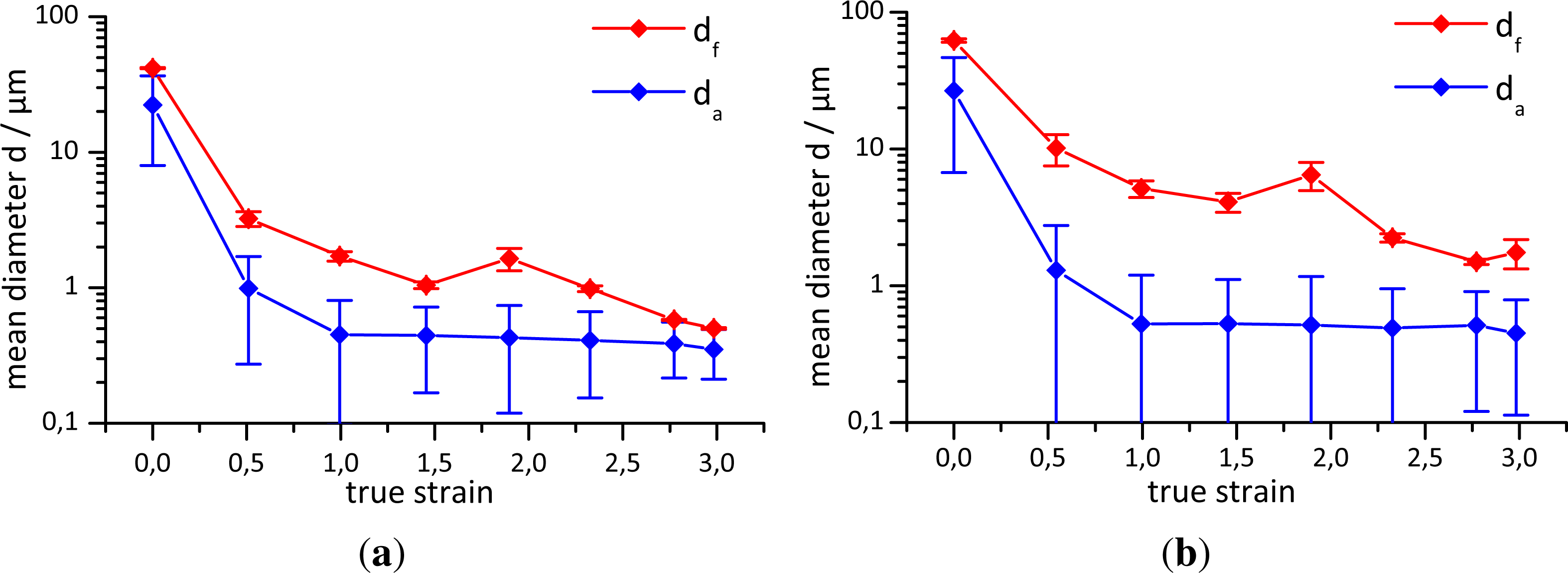
For this reason, two different weighting methods were applied to verify and to discuss the grain size: arithmetic average and grain area-weighted average. Therefore the calculated average is influenced by the grain size/area itself. Small grains strongly influence the arithmetic average, because of their large quantity. The area-weighted average is more sensitive to large grains, due to their large area fraction. The weighted mean value is more representative than the arithmetic average, because large grains were not underestimated. The calculated averages are depicted in Figure 4. The results were obtained from two different criteria. These criteria provide a minimal misorientation angle between two data points, to define a grain boundary. The grain size of grains divided by a 3° or 15° grain boundary are shown in Figure 4a and 4b, respectively. Humphreys and Hatherly distinguish LAGB (Low angle grain boundaries) and HAGB (High angle grain boundaries) due to their energy and migration properties [20]. If the misorientation is less than 15°, the grain boundary is considered as a LAGB. Due to the measurement failure, the lower limit of 3° was declared as the second criterion. The grain size of the initial non-deformed microstructure is in between 20 μm and 70 μm (Figure 4). The arithmetic mean value generally exhibits lowest values, while the area weighted average provides the highest values. The general trend for all graphs shows a decreasing grain size with increasing strain. In the case of area weighted average, the grain size increases at a strain of 1.9. Finally at η = 2.98 the average grain size ranges in between 0.4 μm to 1.8 μm.
The increase of the mean diameter indicates the occurrence of a dynamic recrystallisation in range of η = 1.90. This effect is observed in the area weighted mean diameter only, where large grains are more pronounced. Dynamic recrystallisation may also occur at low strains, but is not recognized because of the large contribution of coarse grains. At η = 1.90 the microstructure is completely fine grained and if DRX is more intense, new grains can grow beyond the recent mean diameter. In this way the values were elevated and DRX could be recognized. Besides the DRX, which can occurs from the beginning, there are also indications of dynamic recovery.
Comparing the diagrams of the two different criteria, the graphs of the diagram for the 15° criterion were shifted to higher values. This fact can be explained by the missing subgrain information. Subgrains are much smaller and the calculated mean diameter consequently decreases, if the subgrains were included in the calculation. There is an additional evidence for the occurrence of subgrains, since da and df shift differently from the 3° to the 15° criterion. The values of da are only slightly increased for the 15° criterion, while df strongly rises from the 3° to the 15° criterion. For 15° the area of subgrains was measured as a part of grains with HAGB. Hence, the increased area of grains with HAGB leads to elevated values of df, while da remains quite unaffected. Considering LAGB by comparing the 15° to the 3° criterion, df values decrease stronger than da values, because coarse grained grains were divided into many subgrains and thereby their area fraction decreases strongly. Therefore, the grain area-weighted mean diameter is more affected than the arithmetic average and this hints to subgrain formation at low strains. Furthermore, the diagram of the 3° criterion exhibits a steeper decrease of the grain size at low strains. This fact is related to the formation of subgrains. Hence, subgrain formation takes place in Mg-alloy AZ31 and provides a mechanism of grain refinement.
At high strain levels the values of the different weighting methods converge, which is due to the narrower grain size distributions. The curves exhibit an asymptotic behaviour at high strains. This indicates, that there is a saturation level of grain refinement caused by SPD, which is in good agreement with literature results [5,6,12–14,21–23]. An explanation could be related to the stacking fault energy (SFE) [24]. Song et al.. discussed the relationship between the minimum grain size in severely deformed materials and the SFE. It seems to be possible to predict the dmin, but the principle mechanism isn’t understood yet [24].
3.2. Texture
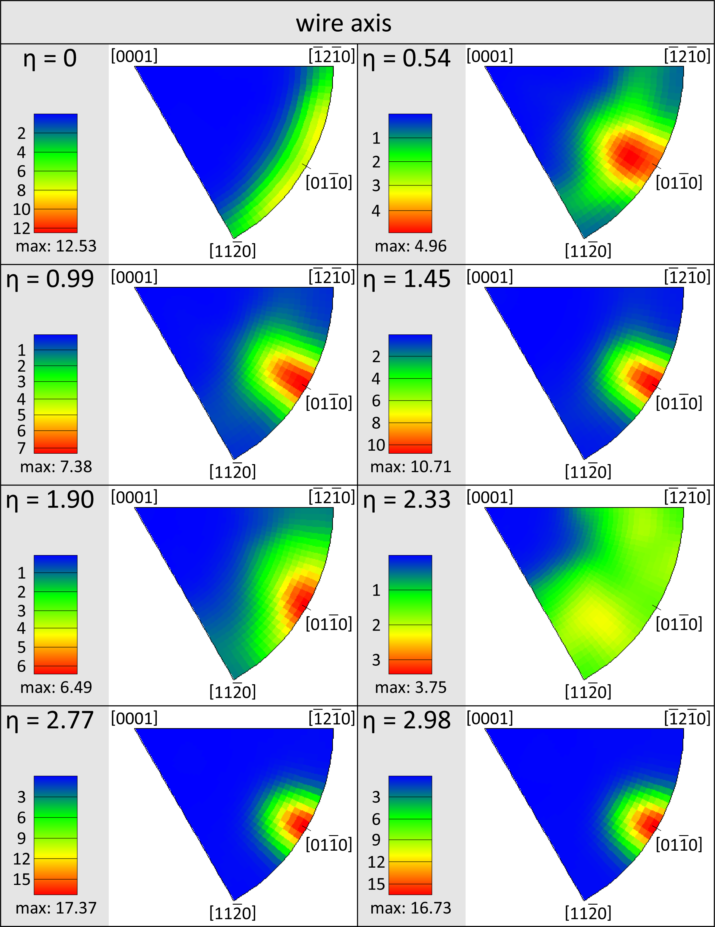
The inverse pole figures derived from EBSD measurements are shown in Figure 5. The initial texture is a ring fibre texture, where the wire axis is randomly oriented within the basal plane. As shown in Figure 5, the deformation by rotary swaging causes the [011̄0] direction to align along the wire axis, while this direction is slightly tilted to the wire axis. This cone fibre texture slightly changes to a centered ring fibre texture with increasing strain. The centered ring fibre texture component consists of an alignment of [011̄0] parallel to the wire axis, which is the final texture caused by rotary swaging. At the strain of 1.90 and 2.33 the ordered texture is weakened. This fact indicates, that dynamic recrystallisation and twinning takes place during deformation. Both, DRX and twinning decrease the former [011̄0] texture component [25,26], due to the reorientation of new grains/twins. This grains/twins change their orientation with further deformation and therefore the [011̄0] centered ring fibre texture is being developed, again.
The texture development in hexagonal metals depends on the c/a ratio and the requirement for the observed texture also concerns the state of stresses. If the c/a ratio is above 1.62, the c-axis aligns parallel to the direction of compression stress [27–29]. In the case of Mg AZ31, the c/a ration is 1.6247 [30], which explains the centered ring fibre texture, because the c-axes are aligned parallel to radial compression stress during deformation. For this reason, wire drawing [31] and rotary swaging lead to radial alignment of c-axis, whereas rotary swaging causes an additional alignment of the wire axis along the [011̄0] direction.
3.3. Twinning
The insufficient number of slip systems explains the limited formability of magnesium. At room temperature there are two basal and two prismatic slip systems, providing only four independent slip systems [32]. At higher temperatures four independent pyramidal slip systems can be activated, which allows a deformation along c-axis [33]. Therefore, the formability of magnesium is enhanced at elevated temperatures [34–36]. However, at RT the Taylor requirement remains non-fulfilled [37] and only twinning can provide the missing fifth deformation system. Relevant twinning systems have been reported elsewhere and a overview is given in Table 1.
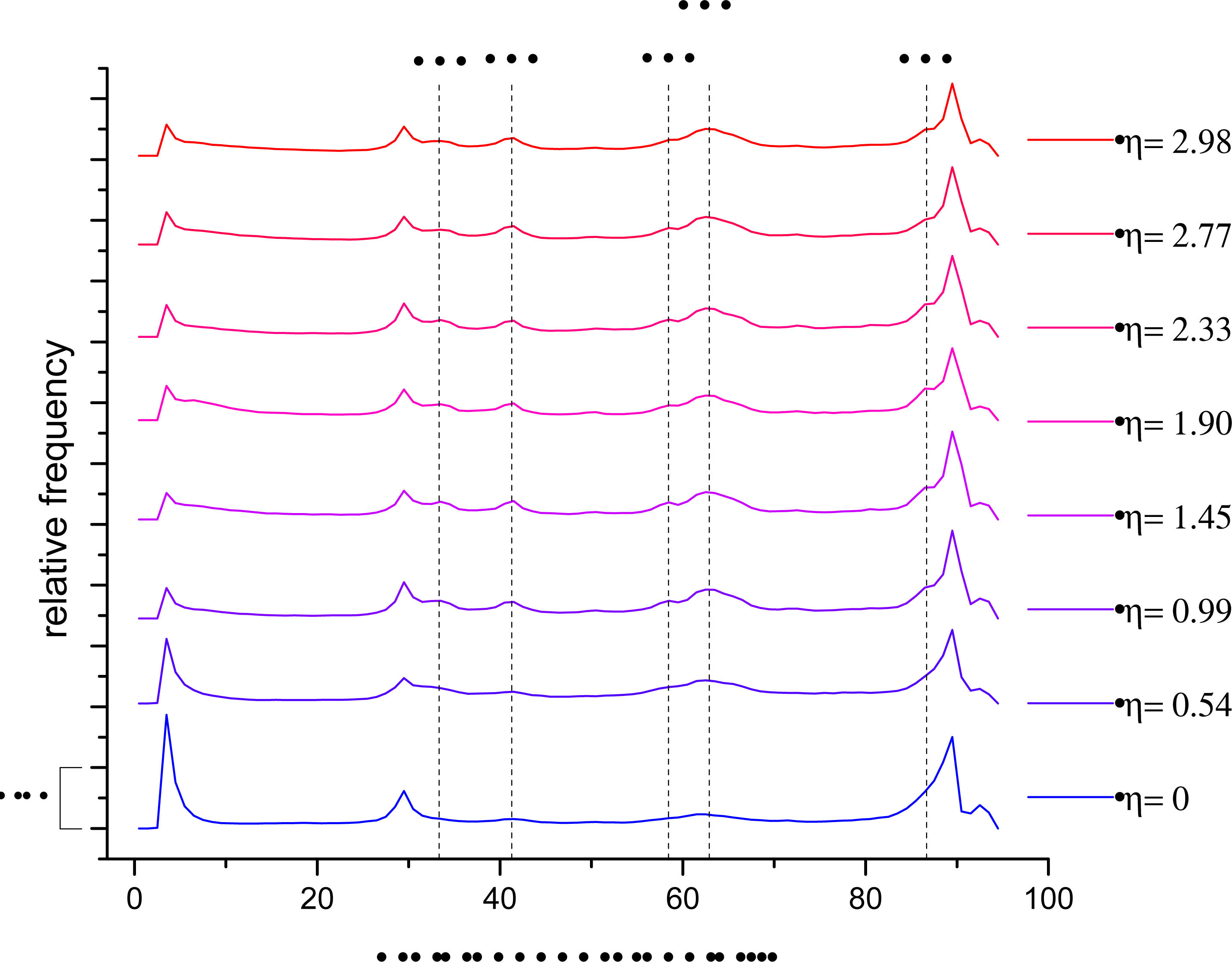
To discuss the grain- and twin boundary evolution with respect to strain, Figure 6 shows the frequency of misorientation angles, which are derived from EBSD measurements as discussed earlier. Boundaries with misorientation angles <3° were not included, because the sample preparation may falsify the frequency of these boundaries. At η = 0 the sample accommodate a misorientation angle distribution with increased frequency for misorientations <10°, 30° and 90°, respectively. The misorientation of 30° and 90° remains independent on deformation strain. Biswas et al.. assigned 90° to a {101̄2}-twin and 30° to a {101̄1}–{101̄2} double twin [11]. This explaination were not utilized here, as the {101̄2}-twin will be assigned to the angle of 86°, which rises as shoulder next to the peak at 90°. The 30° angle may indicate the {101̄1}–{101̄2} double twin, but this will not be investigated in more detail in this work. The initialy elevated frequency of the angles <10° decreases with increasing strain. This fact can be explained by the transformation of LAGB into HAGB. The subgrains exist in the as-received AZ31 and the LAGB will be transformed into HAGB by storage of dislocations into the grain boundaries. This confirms the fact, that the mean diameter curves converge for the 3° and 15° angular deviation between neighbouring grains (see Figure 3). Furthermore, certain misorientation angles show higher frequencies with increasing strain: 33°, 41°, 58°, 63° and 87°. Except of 41°, these angles are also expected for different twinning systems and are summarised in Table 1.
An elevated frequency of misorientation angles at 33° and 58° can be explained by the activation of the {112̄1}and {1̄011} twinning system, respectively. The raised misorientation frequency at the angles 63° and 87° can be associated to other twinning systems: {1̄013} and {112̄2} (63°); {1̄012} and {112̄3} (87°). Thereby, it is not possible to distinguish, which twins are responsible for 63° or 87°. It is expected, that {1̄013} (63°) and {1̄012} (87°) are activated, because these twins are already observed by other authors [39–41,43]. The misorientation angle of 41° does not correspond to any of the discussed twinning systems. Multiple twinning might be one explanation for the accumulating misorientation frequency at this angle. Some double-twinning systems can provide this 41° misorientation, for example: {1̄012}–{112̄2} (42,8°); {1̄012}–{112̄3} (40.7°) and {1̄013}–{112̄3} (41,4°). However, this work cannot evaluate, whether one of these double-twinning systems were activated or not.
3.4. Grain Refinement
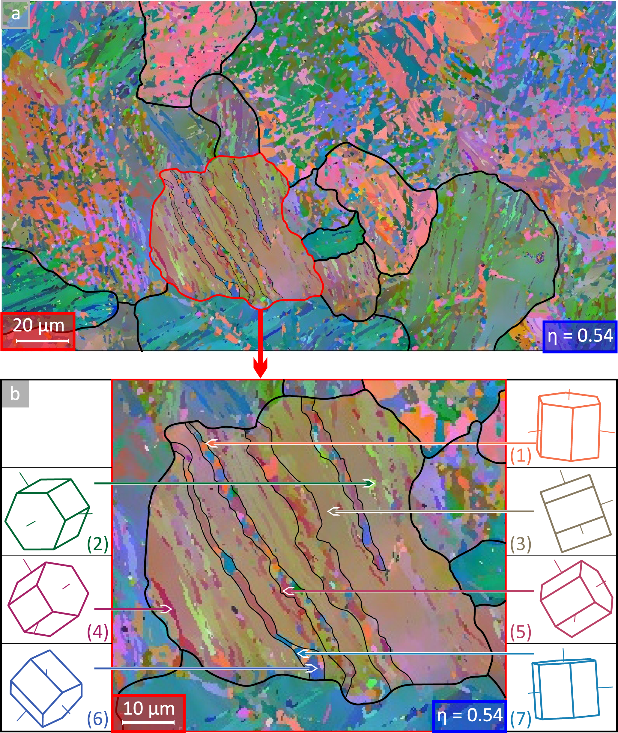
The microstructure of AZ31 at a strain of η = 0.54 was already shown in Figure 2. In Figure 7 the EBSD map is represented in more detail and special features are highlighted concerning the microstructure evolution. At this low strain level the intial grains can be identified and Figure 7a shows the microstructure with grain boundaries of the initial grains. Some crystallite orientations within the grain are shown in Figure 7b. As can be seen in Figure 7, the initial grain contains twins (striped region). Miura et al.. described this as ”fragmentation” of grains [44]. Hence, twinning is the first step of grain refinement.
To evaluate the twinning systems, some misorientations are presented in Figure 7b (1) to (7). The orientation (3) represents the mean orientation of the matrix or host variant. Related to (3), the orientations (4) and (5) corresponds to {1̄012} and {1̄011} twins, respectively. These twins are favorable oriented for dislocation slip with respect to the predominant deformation during swaging. The primary twins weaken the texture, because of their different orientation compared to the host variant. The Schmid factor for basal slip becomes enhanced and dislocations can be easily generated. An increased dislocation density is one necessary condition for DRX and dynamic recovery. From Molodov et al.. point of view, the reorientation of twins provides an increased dislocation activity, which makes recovery also possible due to the rearrangement of dislocations [41]. The initially generated twins provide new boundaries, which can be starting points for nucleation of grains due to DRX [25,26,41,45]. On the other hand, the enhanced dislocation density may cause the generation of LAGB by dislocation arrangement. Further deformation leads to an additional storage of dislocations at LAGB. In this way LAGB can be transformed into HAGB. Valiev et al.. and Sitdikov et al.. explained, that a cellular structure of LAGB is forming during low deformation and that at further deformation these LAGB are transformed to HAGB by storing dislocations at LAGB [6,14]. Twinning is the initial processes of the grain refinement. DRX, dynamic recovery and twinning takes place within primary twins. It seems that there is a limitation of grain refinement, as already discussed for the grain size distribution. The sequence of primary twinning and the following DRX and recovery causes to this limitation. The primary twins grow up to a width of 1–3 μm. This width may provide the limit of new grain as the grain size corresponds to the width of the twin lamella. To conclude the previous facts, the grain size decreases with increasing strain, coarse grains were fragmented by twins and new grains grow within these primary twins.
4. Conclusions
The composite structure of Ti Grade1 and Mg AZ31 was severely plastically deformed up to a true strain of 2.98 at room temperature. The microstructure of AZ31 was examined by SEM-EBSD measurement. The results of this investigation can be summarised as follows:
The grain size and the range of grain size distribution decreases with increasing strain (at η = 2.98 grain size ≤ 10 μm).
Rotary swaging finally leads to a [1̄01̄0] centered ring fibre texture.
Co-deformation of Ti and Mg causes a state of stress, which allows deformation by activating several twinning systems
The grain boundary misorientation frequency indicate the activation of several twinning systems: {112̄1}; {1̄011}; {1̄012} and {1̄013}.
The mean grain refinement mechanism of AZ31 is twinning, whereas initial grains were fragmented by twins. Primary twins are the starting point for further twinning, but also for DRX and recovery.
Acknowledgments
The authors gratefully thank the financial support of EFRE (Europäischer Fonds für regionale Entwicklung) and ADDE project (Atomic Design und Defect-Engineering). Thanks are due to D. Seifert and T. Wolf for experimental support.
References
- Buchmann, W. Magnesium und seine Legierungen; Springer: Berlin, Germany, 2001; Volume 2, Chapter Festigkeitseigenschaften. [Google Scholar]
- Becker, J.; Fischer, G.; Schemme, K. MLight Weight Construction Using Extruded and Forged Semi-Finished Products Made of Magnesium Alloys. In Magnesium Alloys and Their Applications; Mordike, B., Kainer, K., Eds.; Werkstoff-Informationsgesellschaft: Oberursel, Germany, 1998; pp. 15–28. [Google Scholar]
- Gleiter, H. Nanocrystalline materials. Progr. Mater. Sci 1989, 33, 223–315. [Google Scholar]
- Gleiter, H. The mechanism of grain boundary migration. Acta Metall 1969, 17, 565–573. [Google Scholar]
- Valiev, R. Paradoxes of Servere Plastic Deformation. In Nanomaterials by Severe Plastic Deformation; Wiley-VCH: Weinheim, Germany, 2002; pp. 109–117. [Google Scholar]
- Sitdikov, O.; Kaybyshev, R.; Safarov, I.; Mazurina, I. Evolution of the microstructure and mechanisms of formation of new grains upon severe plastic deformation of the 2219 aluminum alloy. Phys. Metals Metallogr 2001, 92, 270–280. [Google Scholar]
- Mukai, T.; Somekawa, H.; Inoue, T.; Singh, A. Strengthening Mg-Al-Zn alloy by repetitive oblique shear strain with caliber roll. Scr. Mater 2010, 62, 113–116. [Google Scholar]
- Ma, A.; Jiang, J.; Saito, N.; Shigematsu, I.; Yuan, Y.; Yang, D.; Nishida, Y. Imroving both strength and ductility of a Mg Alloy through a large number of ECAP passes. Mater. Sci. Eng. A Struct. Mater. Prop. Microstruct. Process 2009, 513–514, 122–127. [Google Scholar]
- Horita, Z.; Matsubara, K.; Miyahara, Y.; Langdon, T.G. Production of Superplastic Mg Alloys Using Severe Plastic Deformation. In Paradoxes of Servere Plastic Deformation; Wiley-VCH: Weinheim, Germany, 2002; pp. 711–716. [Google Scholar]
- Mussi, A.; Blandin, J.; Rauch, E. Microstructure Refinement and Improvement of Mechanical Properties of a Magnesium Alloy by Severe Plastic Deformation. In Paradoxes of Servere Plastic Deformation; Wiley-VCH: Weinheim, Germany, 2002; pp. 740–745. [Google Scholar]
- Biswas, S.; Dhinwal, S.S.; Suwas, S. Room-temperature equal channel angular extrusion of pure magnesium. Acta Mater 2010, 58, 3247–3261. [Google Scholar]
- Bonarski, J.; Alexandrov, I.V. Severely Plastically Deformed Ti from the Standpoint of Texture Changes. In Nanomaterials by Severe Plastic Deformation; Wiley-VCH: Weinheim, Germany, 2002; pp. 309–314. [Google Scholar]
- Furukawa, M.; Horita, Z.; Nemoto, M.; Langdon, T. The use of severe plastic deformation for microstructural control. Mater. Sci. Eng. A 2002, 324, 82–89. [Google Scholar]
- Valiev, R.; Islamgaliev, R.; Alexandrov, I. Bulk nanostructured materials from severe plastic deformation. Progr. Mater. Sci 2000, 45, 103–189. [Google Scholar]
- Marr, T.; Freudenberger, J.; Seifert, D.; Klauß, H.; Romberg, J.; Okulov, I.; Scharnweber, J.; Eschke, A.; Oertel, C.G.; Skrotzki, W.; Kühn, U.; Eckert, J.; Schultz, L. Ti-Al composite wires with high specific strength. Metals 2011, 1, 79–97. [Google Scholar]
- Marr, T.; Freudenberger, J.; Kauffmann, A.; Romberg, J.; Okulov, I.; Petters, R.; Scharnweber, J.; Eschke, A.; Oertel, C.G.; Kühn, U.; Eckert, J.; Skrotzki, W.; Schultz, L. Processing of intermetallic titanium aluminide wires. Metals 2013, 3, 188–201. [Google Scholar]
- Molnár, P.; Jäger, A.; Lejček, P. Twin nucleation at grain boundaries in Mg-3 wt.% Al-1 wt.% Zn alloy processed by equal channel angular pressing. Scr. Mater 2012, 67, 467–470. [Google Scholar]
- Gu, C.F.; Toth, L.S.; Field, D.P.; Fundenberger, J.J.; Zhang, Y.D. Room temperature equal-channel angular pressing of a magnesium alloy. Acta Mater 2013, 61, 3027–3036. [Google Scholar]
- Young, J.; Heiden, M.; Hovanski, Y.; Field, D. Microstructural Analysis of Severe Plastic Deformed Twin Roll Cast AZ31. Proceedings of the Mg2012: 9th International Conference on Magnesium Alloys and their Applications, Vancouver, Canada, July 2012; 9, pp. 1087–1094.
- Humphreys, J.; Hatherly, M. Recrystallization and Related Annealing Phenomena; Volume 2, Elsevier: Amsterdam, The Netherlands, 1996; pp. 91–167. [Google Scholar]
- Cížek, J.; Procházka, I.; Kužel, R.; Cieslar, M.; Stulíková, I.; Islamgaliev, R. Dependence of Thermal Stability of Ultra Fine Grained Metals on Grain Size. In Nanomaterials by Severe Plastic Deformation; Wiley-VCH: Weinheim, Germany, 2002; pp. 630–635. [Google Scholar]
- Perez-Prado, M.; del Valle, J.; Ruano, O. Grain refinement of Mg-Al-Zn alloys via accumulative roll bonding. Scr. Mat 2004, 51, 1093–1097. [Google Scholar]
- Stolyarov, V.; Zhu, Y.; Lowe, T.; Islamgaliev, R.; Valiev, R. A two step SPD processing of ultrafine-grained titanium. Nanostruct. Mater 1999, 11, 947–954. [Google Scholar]
- Song, L.; Qing-Miao, H.; Delczeg-Czirjak, E.; Johansson, B.; Vitos, L. Determining the minimum grain size in severe plastic deformation process via first-principles calculations. Acta Mater 2012, 60, 4506–4513. [Google Scholar]
- Liang, S.; Okrutny, P.; Wang, X.; Zurob, H. Recrystallization Nucleation Sites in Deformed AZ31. Proceedings of the Mg2012: 9th International Conference on Magnesium Alloys and their Applications, Vancouver, Canada, July 2012; 9, pp. 663–668.
- Schmidt, C.; Kawalla, R. Decomposing the Basal Texture in Rolled AZ31 Magnesium Sheets. Proceedings of the Mg2012: 9th International Conference on Magnesium Alloys and their Applications, Vancouver, Canada, July 2012; 9, pp. 367–373.
- Schmid, E.; Wassermann, G. Über die Walztexturen hexagonaler Metalle. Metallwirtschaft 1930, 9, 698–702. [Google Scholar]
- Agnew, S.; Yoo, M.; Tomé, C. Application of texture simulation to understanding mechanical behavior of Mg and solid solution alloys containing Li or Y. Acta Mater 2001, 49, 4277–4289. [Google Scholar]
- Al-Samman, T. Comparative study of the deformation behavior of hexagonal magnesium-lithium alloys and a conventional magnesium AZ31 alloy. Acta Mater 2009, 57, 2229–2242. [Google Scholar]
- Pekguleryuz, M.; Celikin, M.; Hoseini, M.; Becerra, A.; Mackenzie, L. Study on edge cracking and texture evolution during 150 °C rolling of magnesium alloys: The effects of axial ratio and grain size. J. Alloys Compd 2012, 510, 15–25. [Google Scholar]
- Wassermann, G.; Grewen, J. Texturen Metallischer Werkstoffe; Springer: Berlin, Germany, 1962. [Google Scholar]
- Roberts, C. The Deformation of Magnesium. In Magnesium and Its Alloys; Wiley, 1964; p. 81ff. [Google Scholar]
- Reed-Hill, R.; Robertson, W. Pyramidal slip in magnesium. Trans. Am. Inst. Min. Metall. Eng 1958, 212, 256–259. [Google Scholar]
- Chaudhuri, A.; Chang, H.; Grant, N. Creep deformation of magnesium at elevated temperatures by nonbasal slip. Trans. Am. Inst. Min. Metall. Eng 1955, 203, 682–688. [Google Scholar]
- Flynn, P.; Mote, J.; Dorn, J. On the thermally activated mechanism of prismatic slip in magnesium single crystals. Trans. Metall. Soc. AIME 1961, 221, 1148–1154. [Google Scholar]
- Watanabe, H.; Tsutsui, H.; Mukai, T.; Kohzu, M.; Tanabe, S.; Higashi, K. Deformation mechanism in a coarse-grained Mg-Al-Zn alloy at elevated temperatures. Int. J. Plast 2001, 17, 387–397. [Google Scholar]
- Taylor, G. Plastic strain in metals. J. Inst. Metals 1938, 62, 307–324. [Google Scholar]
- Barnett, M.; Keshavarz, Z.; beer, A.; Ma, X. Non-Schmid behaviour during secondary twinning in a polycrystalline magnesium alloy. Acta Mater 2008, 56, 5–15. [Google Scholar]
- Barnett, M. Twinning and the ductility of magnesium alloys Part I: “Tension” twins. Mater. Sci. Eng. A 2007, 464, 1–7. [Google Scholar]
- Reed-Hill, R. A study of the {101̄1} and {101̄3} twinning modes in magnesium. Trans. Am. Inst. Min. Metall. Eng 1960, 218, 554–558. [Google Scholar]
- Molodov, K.; Al-Samman, T.; Molodov, D.A. Dynamic Recrystallization in Magnesium Monocrystals. Proceedings of the Mg2012: 9th International Conference on Magnesium Alloys and their Applications, Vancouver, Canada, July 2012; 9, pp. 651–656.
- Stanford, N. Observation of {112̄1} twinning in a Mg-based alloy. Philos. Mag. Lett 2008, 88, 379–386. [Google Scholar]
- Jain, A.; Duygulu, O.; Brown, D.; Tomé, C.; Agnew, S. Grain size effects on the tensile properties and deformation mechanisms of a magnesium alloy, AZ31B, sheet. Mater. Sci. Eng. A 2008, 486, 545–555. [Google Scholar]
- Miura, H.; Yang, X.; Jonas, J. Microstructure and Mechanical Properties of Multi-Directionally Forged AZ61 Mg Alloy. Proceedings of the Mg2012: 9th International Conference on Magnesium Alloys and their Applications, Vancouver, Canada, July 2012; 9, pp. 725–729.
- Schwarz, F.; Krüger, L.; Roven, H.J.; Martin, U. Microstructural and Mechanical Characterization of ECAPed AZ-Magnesium Alloys. Proceedings of the Mg2012: 9th International Conference on Magnesium Alloys and their Applications, Vancouver, Canada, July 2012; 9, pp. 1129–1135.


| Literature | Twin plane | Shear direction | Twin boundary misorientation | |
|---|---|---|---|---|
| Calculated | Observed | |||
| [38] | {1̄011} | 〈101̄2〉 | 56° | 58° |
| [39] | {1̄012} | 〈101̄1&rang | 87° | 87° |
| [40,41] | {1̄013} | 〈303̄2〉 | 64° | 63° |
| {1̄014} | 〈202̄1&rang | 50° | ||
| [42] | {112̄1} | 〈1̄1̄26〉 | 34° | 33° |
| {112̄2} | 〈1̄1̄23〉 | 64° | 63° | |
| {112̄3} | 〈1̄1̄62〉 | 85° | 87° | |
| {112̄4} | 〈2̄2̄43〉 | 78° | ||
© 2013 by the authors; licensee MDPI, Basel, Switzerland This article is an open access article distributed under the terms and conditions of the Creative Commons Attribution license (http://creativecommons.org/licenses/by/3.0/).
Share and Cite
Knauer, E.; Freudenberger, J.; Marr, T.; Kauffmann, A.; Schultz, L. Grain Refinement and Deformation Mechanisms in Room Temperature Severe Plastic Deformed Mg-AZ31. Metals 2013, 3, 283-297. https://doi.org/10.3390/met3030283
Knauer E, Freudenberger J, Marr T, Kauffmann A, Schultz L. Grain Refinement and Deformation Mechanisms in Room Temperature Severe Plastic Deformed Mg-AZ31. Metals. 2013; 3(3):283-297. https://doi.org/10.3390/met3030283
Chicago/Turabian StyleKnauer, Enrico, Jens Freudenberger, Tom Marr, Alexander Kauffmann, and Ludwig Schultz. 2013. "Grain Refinement and Deformation Mechanisms in Room Temperature Severe Plastic Deformed Mg-AZ31" Metals 3, no. 3: 283-297. https://doi.org/10.3390/met3030283