Rate Dependence of the Compressive Response of Ti Foams

Abstract
:1. Introduction
 , produced by optimizing the space-holder method. The materials were deformed at low and medium strain rates (10−3–6 × 10⁻⁶) and were found to be mildly strain rate sensitive in this range. Thelen et al.[13] worked with sintered foams obtained from both commercially pure Ti and TiAl6V4 powders, of relative densities in the range of
  . Specimens were subjected to quasi-static mechanical loading in order to determine their elastic properties, and found them in good agreement with the predictions of Mori and Tanaka [14] and Ashby and Gibson [15]. The fragmented existing experimental studies [12] suggest that Ti foams can be mildly sensitive to strain rate in compression. This is in contrast with the results reported by other authors on lower-density Al foams [16,17], which show a rate-insensitive response. In this study, we focus on the compressive properties of pure Ti foams produced using a powder metallurgy process [18] and the measured responses are compared with those of Ti powder sintered under similar conditions to the foams. In order to understand the dependence of the material response on relative density and strain rate, foams with
  are tested in compression at strain rates from 0.01 to 2,000 s−1.
2. Experimental Procedures and Results
2.1. Material Manufacturing
2.2. Geometrical Analysis of the Foam Microstructure
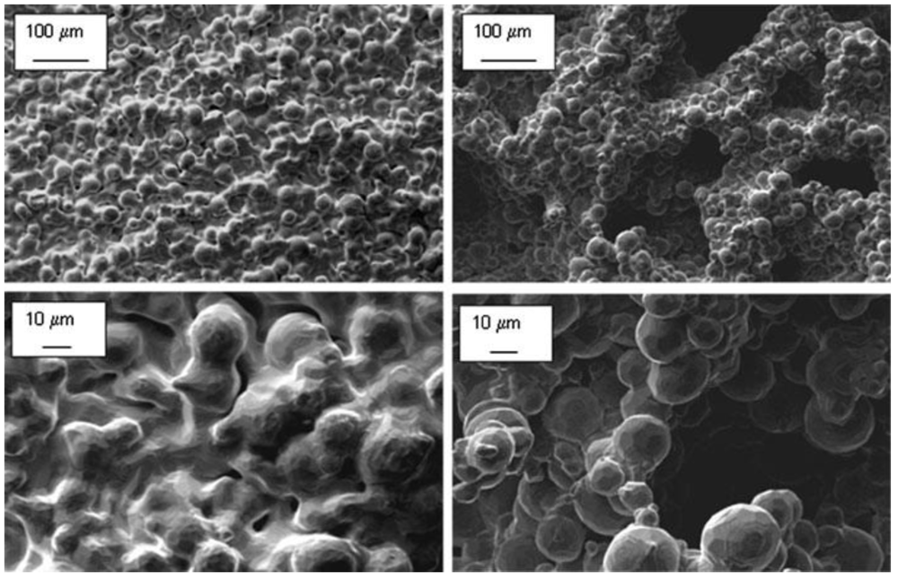
 ), produced by powder sintering with the foaming agent absent, powder particles are nearly completely sintered and only small micro-voids are observed, of diameter around 10 μm. Foams of low relative density (
  ), display larger macro-voids of diameter ranging from 100 to 300 μm; the degree of sintering is lower for these foams compared with that of high-density foams., left) and low-density ( , right) foams.
, left) and low-density ( , right) foams.
), display larger macro-voids of diameter ranging from 100 to 300 μm; the degree of sintering is lower for these foams compared with that of high-density foams., left) and low-density ( , right) foams.
, left) and low-density ( , right) foams.
2.3. Quasi-Static Uniaxial Compression Experiments
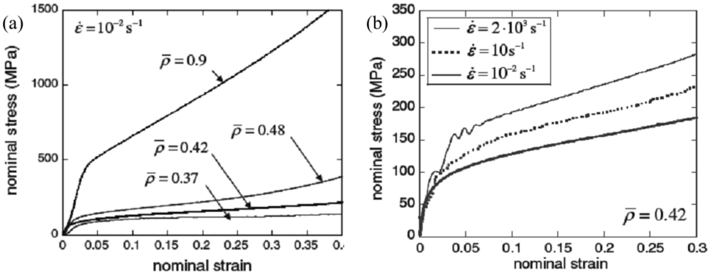
 were tested in uniaxial compression at strain rates of 0.01 s−1. Circular cylindrical specimens of diameter 11 mm and height of 13 mm were compressed in the axial direction. A screw driven machine in displacement control was used to conduct the experiments. The compressive force was measured by a resistive load cell, and the shortening of the sample was measured by a laser extensometer and was used to calculate the compressive strain. Experiments were interrupted when an axial strain larger than 0.5 was achieved. Figure 2a presents the measured stress versus strain curves for samples of four different densities. Image correlation was used to measure transverse deformation of the sample; the ratio of this transverse strain to the imposed compressive axial strain is defined as the material Poisson’s ratio. Tests showed the elastic modulus scales with relative density according to a power-law of exponent 1.08 which is approximately half of that predicted by Ashby et al. [15] for low density polymeric foams.
 .
.
.
.
2.4. Dynamic Compression Experiments
at different strain rates. at low, medium and high strain rates.
at low, medium and high strain rates.
at low, medium and high strain rates.
2.5. FE Simulations of the Compressive Response
 ) was found to be 0.016. Figure 4 and Figure 5 display samples of the mesh and the FE predictions of the macroscopic compressive response at low (~0.01/s) and high (~1,000/s) strain rate, for foams of two selected densities. By comparing with the data in Figure 3 (left), it is evident that the FE simulations predict accurately the yield stress for these foams.
 ; (Right) FE predictions of the macroscopic material responses.
; (Right) FE predictions of the macroscopic material responses.
; (Right) FE predictions of the macroscopic material responses.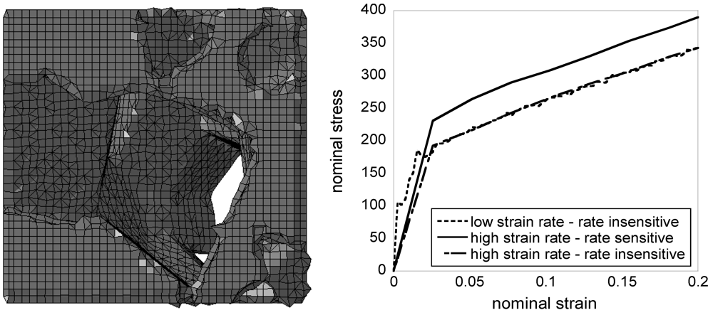
 ; (Right) FE predictions of the macroscopic material responses.
; (Right) FE predictions of the macroscopic material responses.
; (Right) FE predictions of the macroscopic material responses.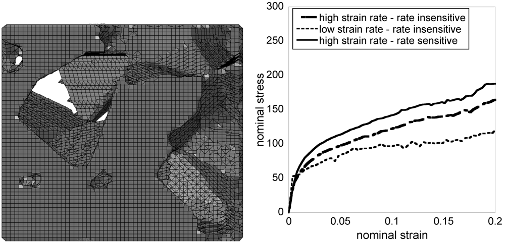
3. Discussion
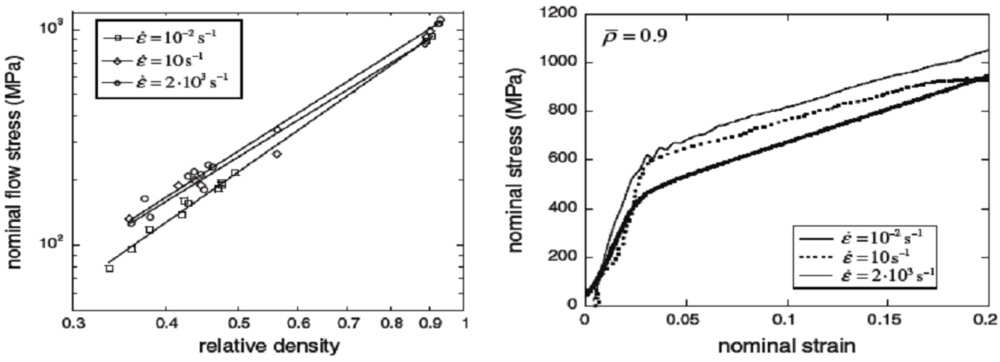
 ) displays an increase of the yield stress with strain rate comparable to those observed by other authors [6,7,8] for fully dense crystalline Ti alloys. This elevation in yield stress was measured to be of 13% as the strain rate was varied from 0.01 to 2,000 s−1; for these sintered powders, the measured strain hardening rate is independent of the applied strain rates. Foams (
  ) display an elevation of both yield stress and strain hardening rate with increasing applied strain rate. Foams with relative density
  displayed an elevation of 32% in flow stress (at a plastic strain of 0.2) as the strain rate was varied from 0.01 to 2,000 s−1. In more quantitative terms, the measured flow stress (at a plastic strain of 0.2)
  versus imposed strain rate (
  ) data could be fitted by a power-law relation of type , where A and m were a function of relative density. The measured exponents m were found to be 0.027 and 0.017 for relative densities of 0.35 and 0.9, respectively.
4. Conclusions
Acknowledgments
References
- Long, M.; Rack, H.J. Titanium alloys in total joint replacement—A material science perspective. Biomaterials 1998, 19, 1621–1639. [Google Scholar] [CrossRef]
- Nemat-Nasser, S.; Guo, W.G.; Cheng, J.Y. Mechanical properties and deformation mechanisms of commercially pure Titanium. Acta Mater. 1999, 47, 3705–3720. [Google Scholar] [CrossRef]
- Ashby, M.F.; Evans, A.G.; Fleck, N.A.; Hutchinson, J.W.; Wadley, H.N.G.; Gibson, L.J. Making metal foams. In Metal Foams: A Design Guide; Butterworth-Heinemann: Burlington, MA, USA, 2000. [Google Scholar]
- Lefebvre, L.P.; Baril, E.; Bureau, M.N. Effect of the oxygen content in solution on the static and cyclic deformation of titanium foams. J. Mater. Sci. Mater. Med. 2009, 20, 2223–2233. [Google Scholar] [CrossRef] [Green Version]
- Jorgensen, D.J.; Dunand, D.C. Ti-6Al-4V with micro- and macropores produced by powder sintering and electrochemical dissolution of steel wires. Mater. Sci. Eng. A 2010, 527, 849–853. [Google Scholar] [CrossRef]
- Guden, M.; Celik, E.; Akar, E.; Cetiner, S. Compression testing of a sintered Ti6Al4V powder compact for biomedical applications. Mater. Char. 2005, 54, 399–408. [Google Scholar] [CrossRef]
- Rouxel, A.; Chiem, C.Y. Strain-rate history effects on TiAl6V4 titanium alloy. Impact Loading Dynam. Behav. Mater. 1988, 2, 601–608. [Google Scholar]
- Meyer, L.W.; Krüger, L.; Razorenov, S.V.; Kanel, G.I. Investigation of dynamic flow and strength properties of Ti-6-22-22S at normal and elevated temperatures. In. J. Impact Eng. 2003, 28, 877–890. [Google Scholar] [CrossRef]
- Wen, C.E.; Yamada, Y.; Shimojima, K.; Chino, Y.; Asahina, T.; Mabuchi, M. Processing and mechanical properties of autogenious titanium implant materials. J. Mater. Sci. Mater. Med. 2002, 13, 397–401. [Google Scholar] [CrossRef]
- Wen, C.E.; Mabuchi, M.; Yamada, Y.; Shimojima, K.; Chino, Y.; Asahina, T. Processing of biocompatible porous Ti and Mg. Scr. Mater. 2001, 45, 1147–1153. [Google Scholar] [CrossRef]
- Imwinkelried, T. Mechanical properties of open-pore titanium foam. J. Biomed. Mater. Res. A 2007, 81A, 964–970. [Google Scholar] [CrossRef]
- Tuncer, N.; Arslan, G. Designing compressive properties of titanium foams. J. Mater. Sci. 2009, 44, 1477–1484. [Google Scholar] [CrossRef]
- Thelen, S.; Barthelat, F.; Brinson, L.C. Mechanics considerations for microporous titanium as an orthopedic implant material. J. Biomed. Mater. Res. 2004, 69A, 601–610. [Google Scholar] [CrossRef]
- Mori, T.; Tanaka, K. Average stress in matrix and average elastic energy of materials with misfitting inclusions. Acta Metall. 1973, 21, 571–574. [Google Scholar] [CrossRef]
- Ashby, M.F.; Gibson, L.J. Mechanics of foams. In Cellular Solids: Structure and Properties; Cambridge University Press: New York, NY, USA, 1997. [Google Scholar]
- Deshpande, V.S.; Fleck, N.A. Isotropic constitutive models for metallic foams. J. Mech. Phys. Solid. 2000, 48, 1253–1283. [Google Scholar] [CrossRef]
- Radford, D.D.; Deshpande, V.S.; Fleck, N.A. The use of metal foam projectile to simulate shock loading on a structure. Int. J. Impact Eng. 2005, 31, 1152–1171. [Google Scholar] [CrossRef]
- Lefebvre, L.P.; Thomas, Y. Method of Making Open Cell Material. U.S. Patent 6,660,224, 9 December 2003. [Google Scholar]
- Shen, H.; Oppenheimer, S.M.; Dunand, D.C.; Brinson, L.C. Numerical modeling of pore size and distribution in foamed titanium. Mech. Mater. 2006, 38, 933–944. [Google Scholar] [CrossRef]
- Borovinsek, M.; Ren, Z. Computational modelling of irregular open-cell foam under impact loading. Mater. Sci. Eng. Technol. 2008, 39, 114–120. [Google Scholar]
- Gray, G.T. Classic Split Hopkinson Pressure Bar Testing; ASM International: Materials Park, OH, USA, 2000; pp. 462–476. [Google Scholar]
- Voronoi, G. Nouvelles applications des paramètres continus à la théorie des formes quadratiques. J. Pure Appl. Math. 1908, 133, 97–178. [Google Scholar]
- Beta CAE Systems S.A. Ansa v. 12.1.3 User’s Guide; Makedonia Palace: Thessaloniki, Greece, 2008; Volume Meshing, pp. 503–575, Chapter 10.
- Abaqus Analysis User’s Manual, Classical Metal Plasticity, Rate Dependence-Direct Tabular Data. Simulia Abaqus CAE 6.9 Documentation. Maastricht, The Nethelands, 2009.
© 2012 by the authors; licensee MDPI, Basel, Switzerland. This article is an open-access article distributed under the terms and conditions of the Creative Commons Attribution license (http://creativecommons.org/licenses/by/3.0/).
Share and Cite
Siegkas, P.; Tagarielli, V.L.; Petrinic, N.; Lefebvre, L.-P. Rate Dependence of the Compressive Response of Ti Foams. Metals 2012, 2, 229-237. https://doi.org/10.3390/met2030229
Siegkas P, Tagarielli VL, Petrinic N, Lefebvre L-P. Rate Dependence of the Compressive Response of Ti Foams. Metals. 2012; 2(3):229-237. https://doi.org/10.3390/met2030229
Chicago/Turabian StyleSiegkas, Petros, Vito L. Tagarielli, Nik Petrinic, and Louis-Philippe Lefebvre. 2012. "Rate Dependence of the Compressive Response of Ti Foams" Metals 2, no. 3: 229-237. https://doi.org/10.3390/met2030229