Micro-Pitting and Wear Assessment of PAO vs Mineral-Based Engine Oil Operating under Mixed Lubrication Conditions: Effects of Lambda, Roughness Lay and Sliding Direction


 , and
, and
Abstract
:
1. Introduction
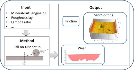
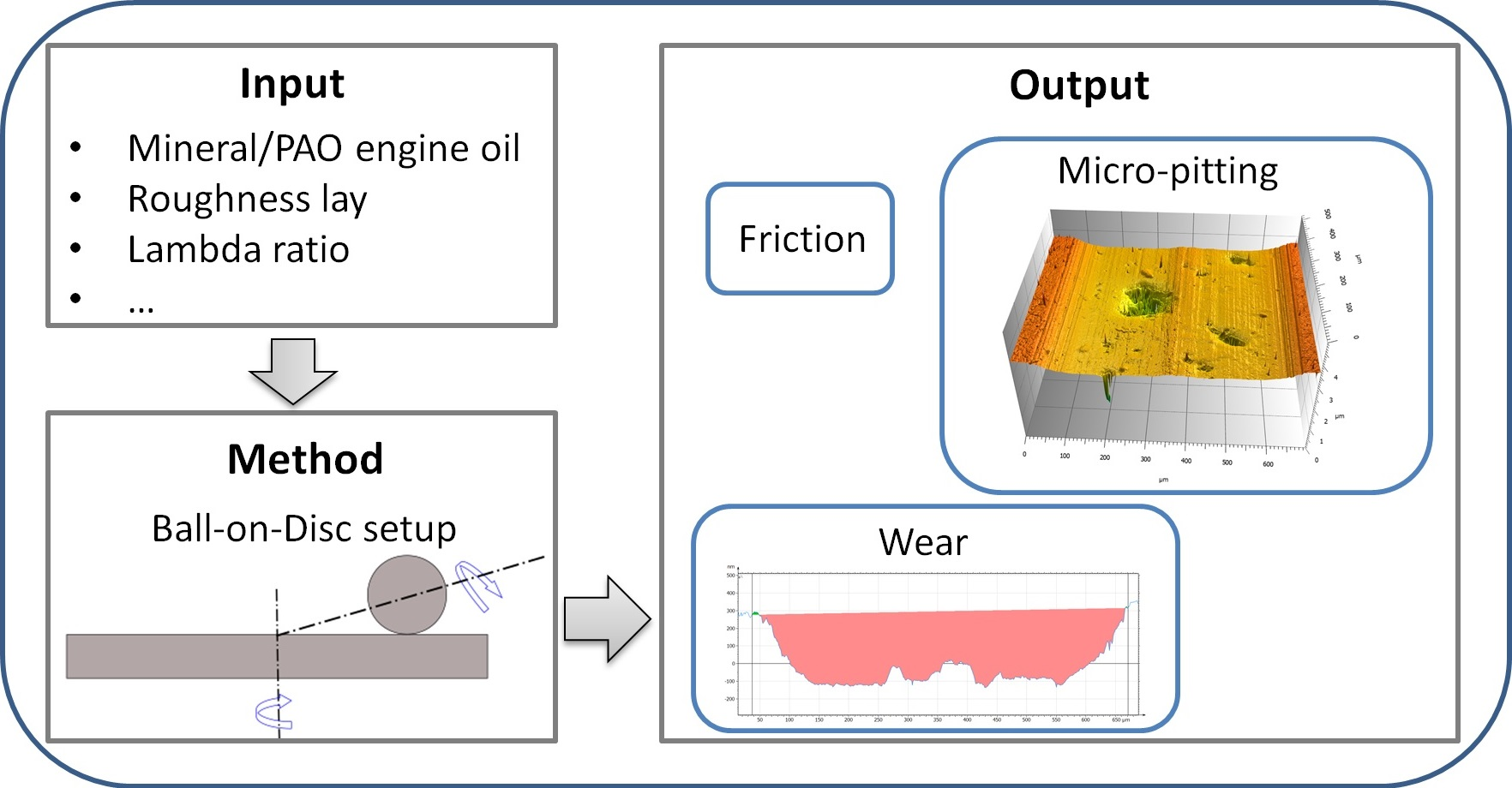
2. Methodology
2.1. Test Lubricants and Specimens
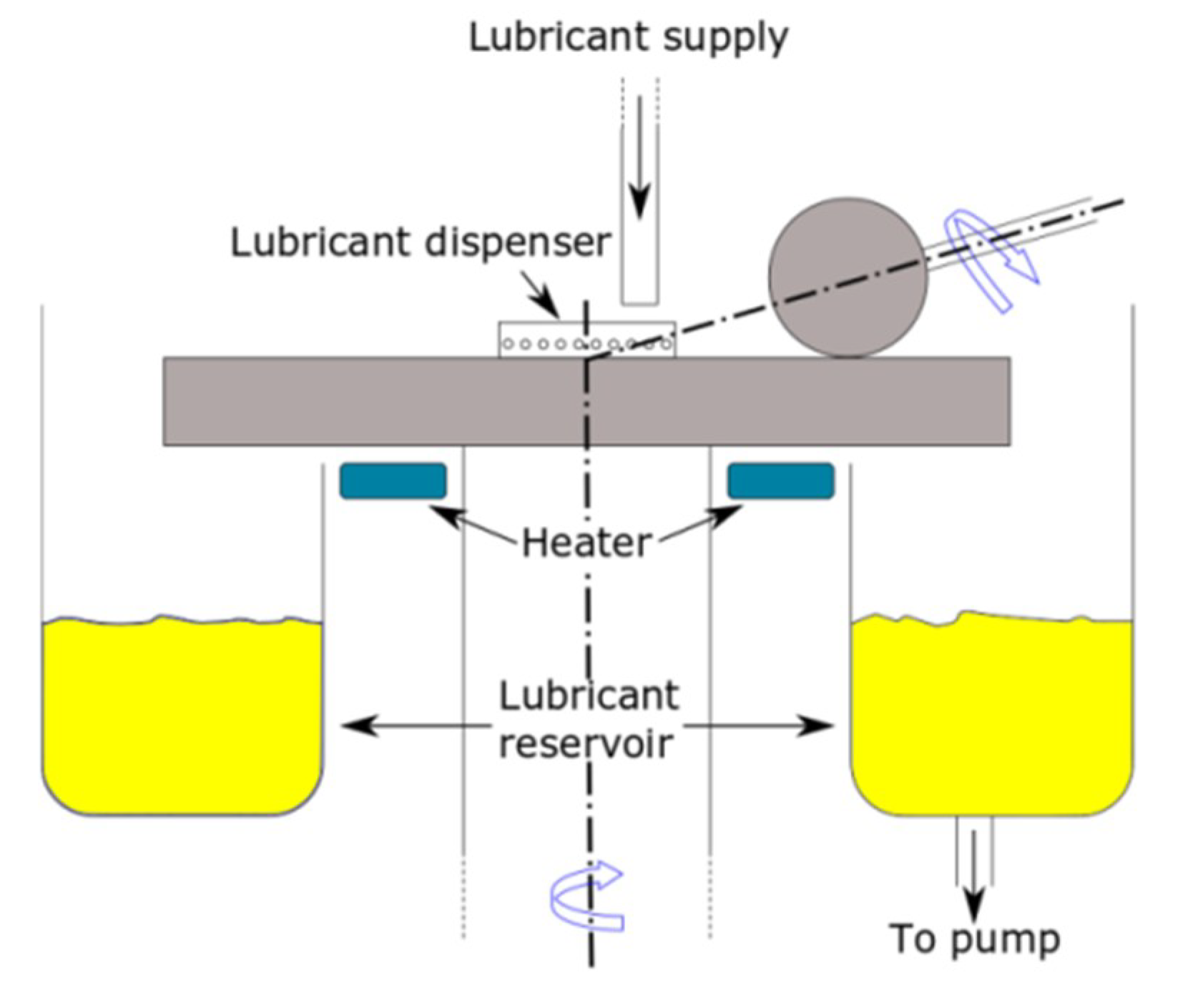
2.2. Testing Procedure
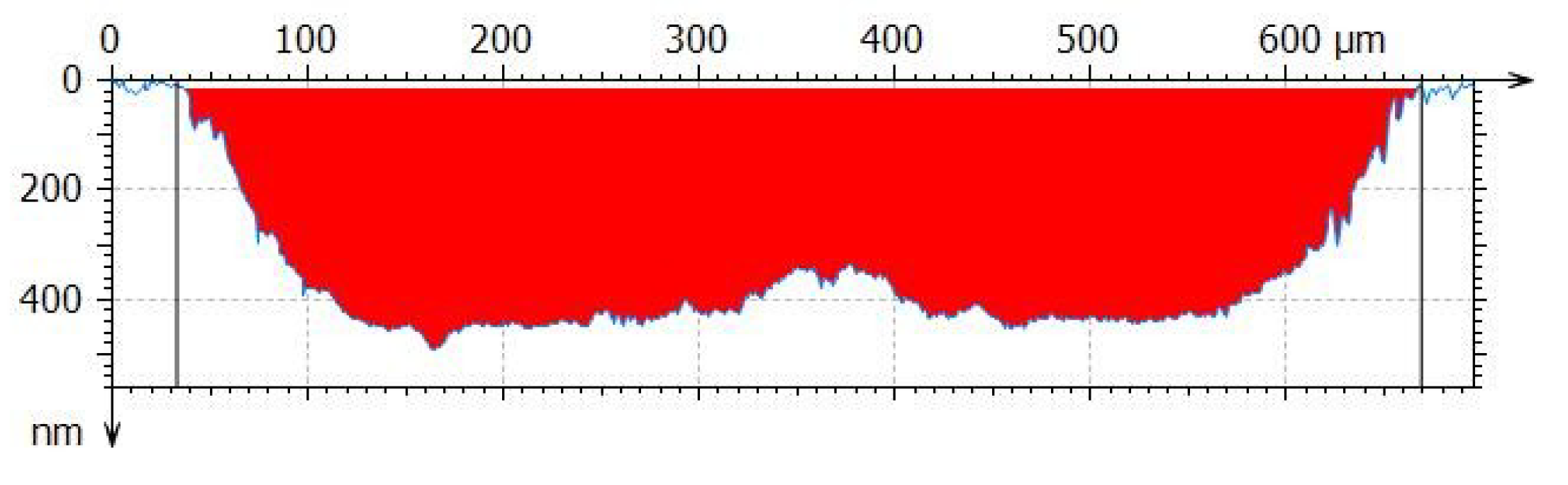
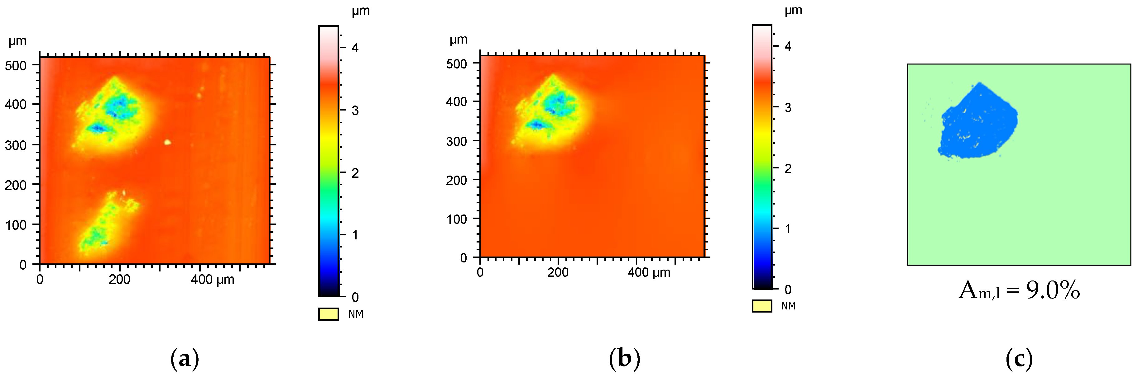
2.3. Post Analysis
3. Results and Discussion
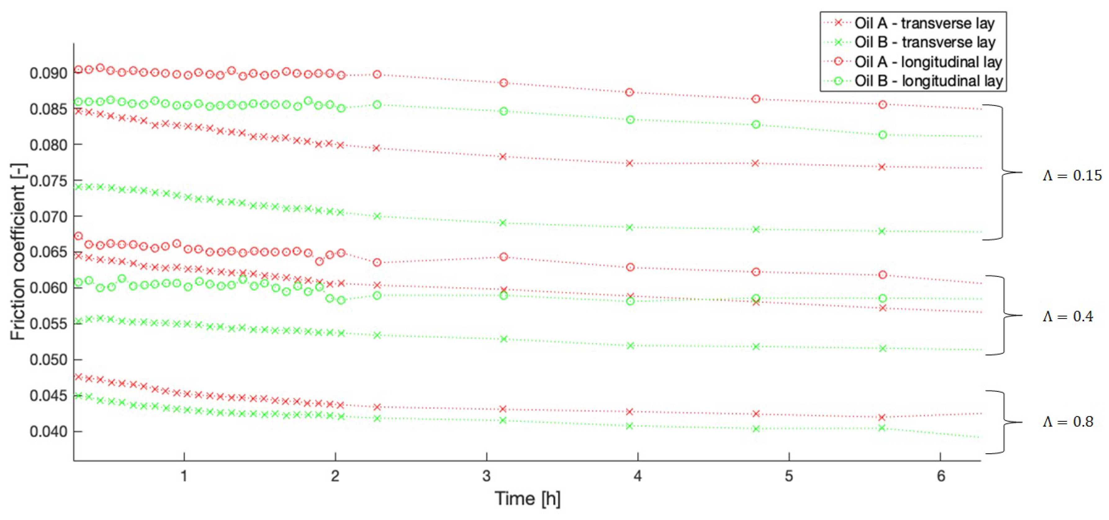
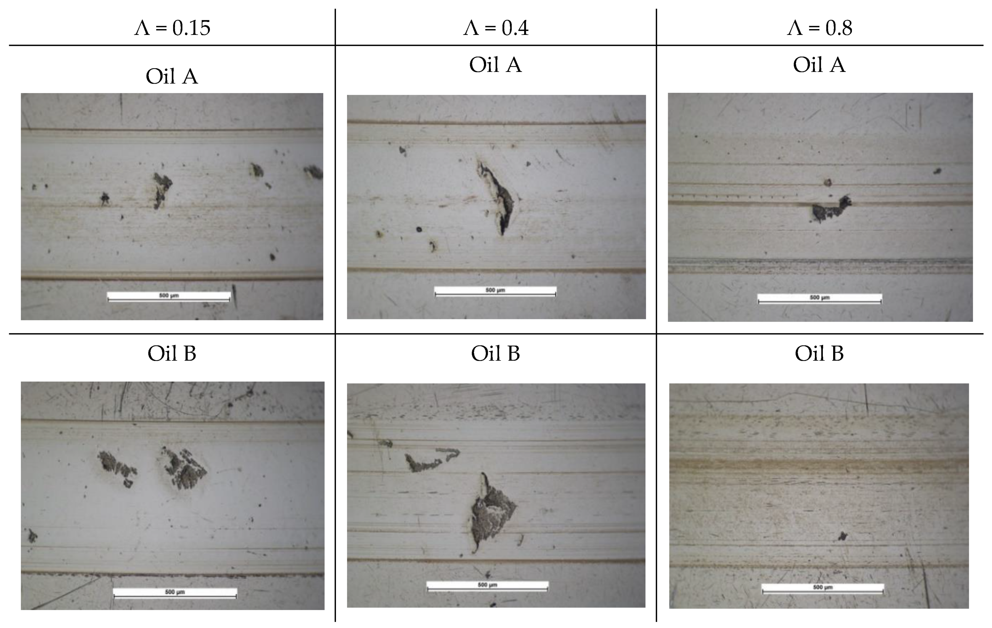
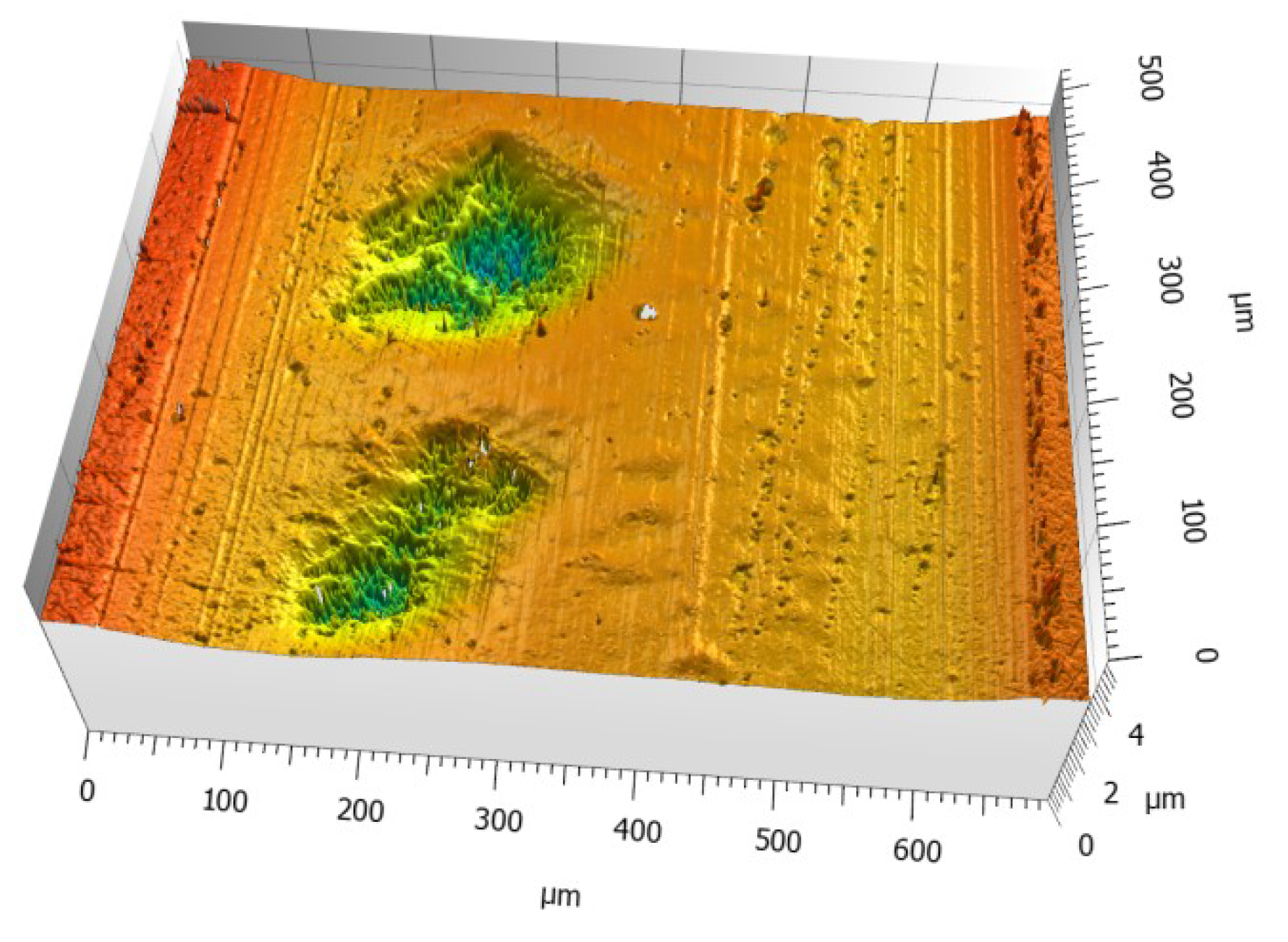
3.1. Effects of Lambda, Roughness Lay and Type of Base Oil on Micro-Pitting and Wear
3.2. Effect of Sliding Direction on Micro-Pitting and Wear Damage
4. Conclusions
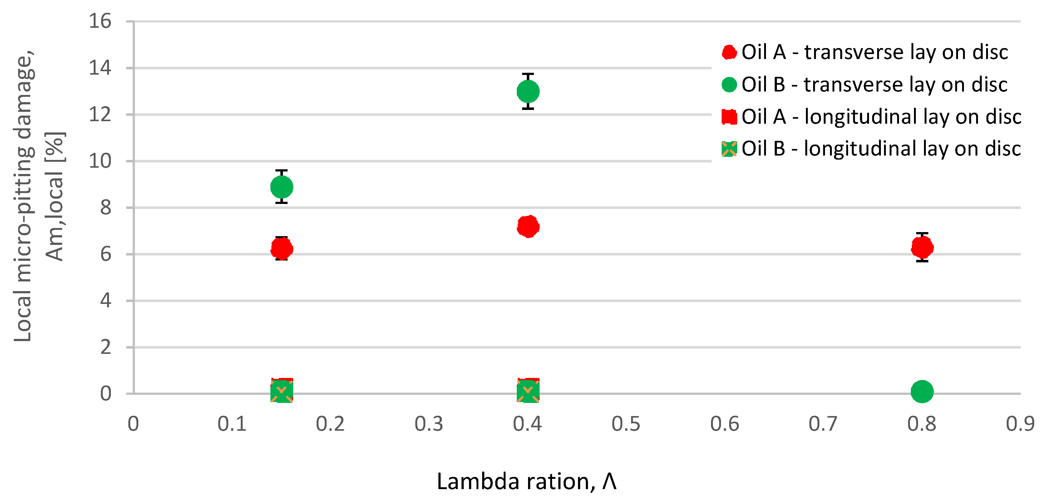
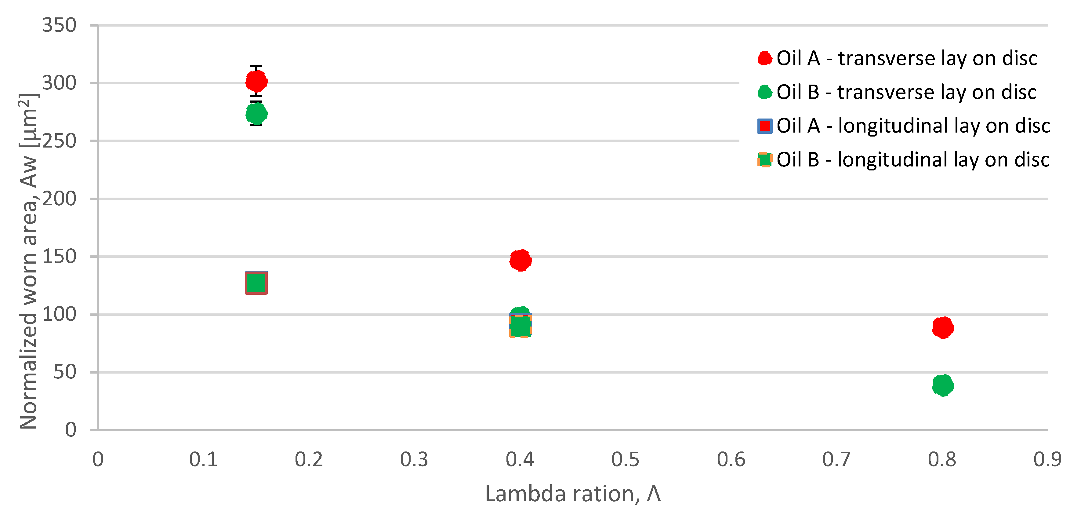
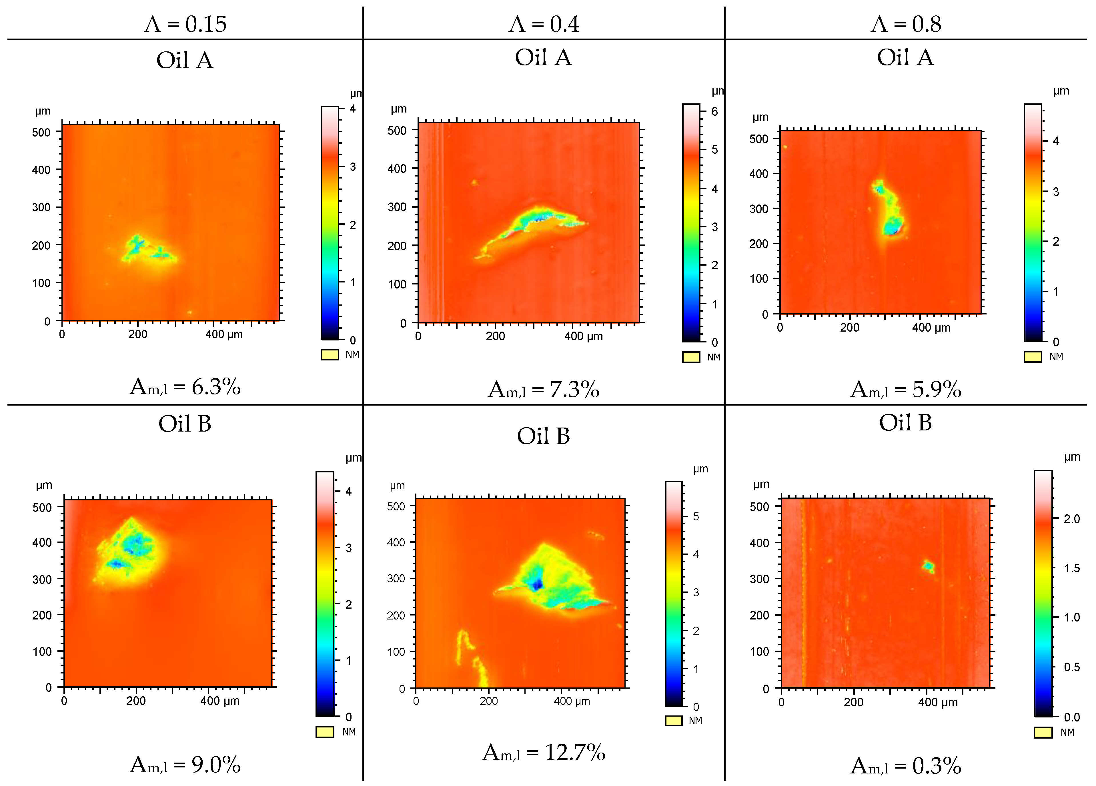
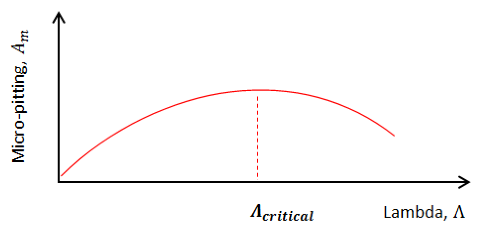
- Micro-pitting damage is more evenly distributed at a low lambda ratio (Λ = 0.15) which is accompanied by relatively high wear. This, in turn, reduces the size of a single micro-pitting damage, which is the highest at a critical/intermediate lambda (Λ = 0.4). Further increase in lambda reduces the severity of the contact, thus, reduces micro-pitting and wear damage.
- For transverse roughness lay, PAO base oil completely eliminates micro-pitting damage at a high lambda ratio (Λ = 0.8) in comparison to mineral base oil. However, at lower lambda ratios, micro-pitting damage is present for both base oils and the size of a single micro-pitting damage is higher for PAO base oil compared to mineral oil, due to lower wear.
- Longitudinal roughness lay, almost completely eliminates the tendency towards micro-pitting compared to transverse lay. In addition, wear damage is lower for longitudinal lay at low lambda (Λ = 0.15). Different base oil type does not show any clear difference in wear damage for longitudinal roughness lay.
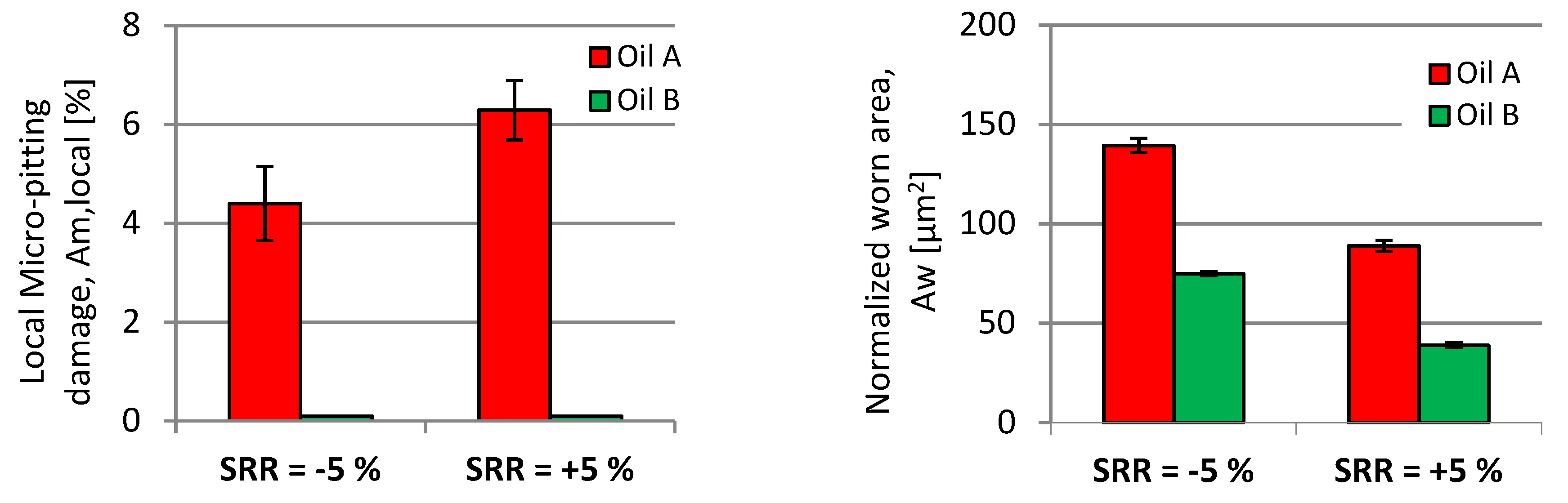
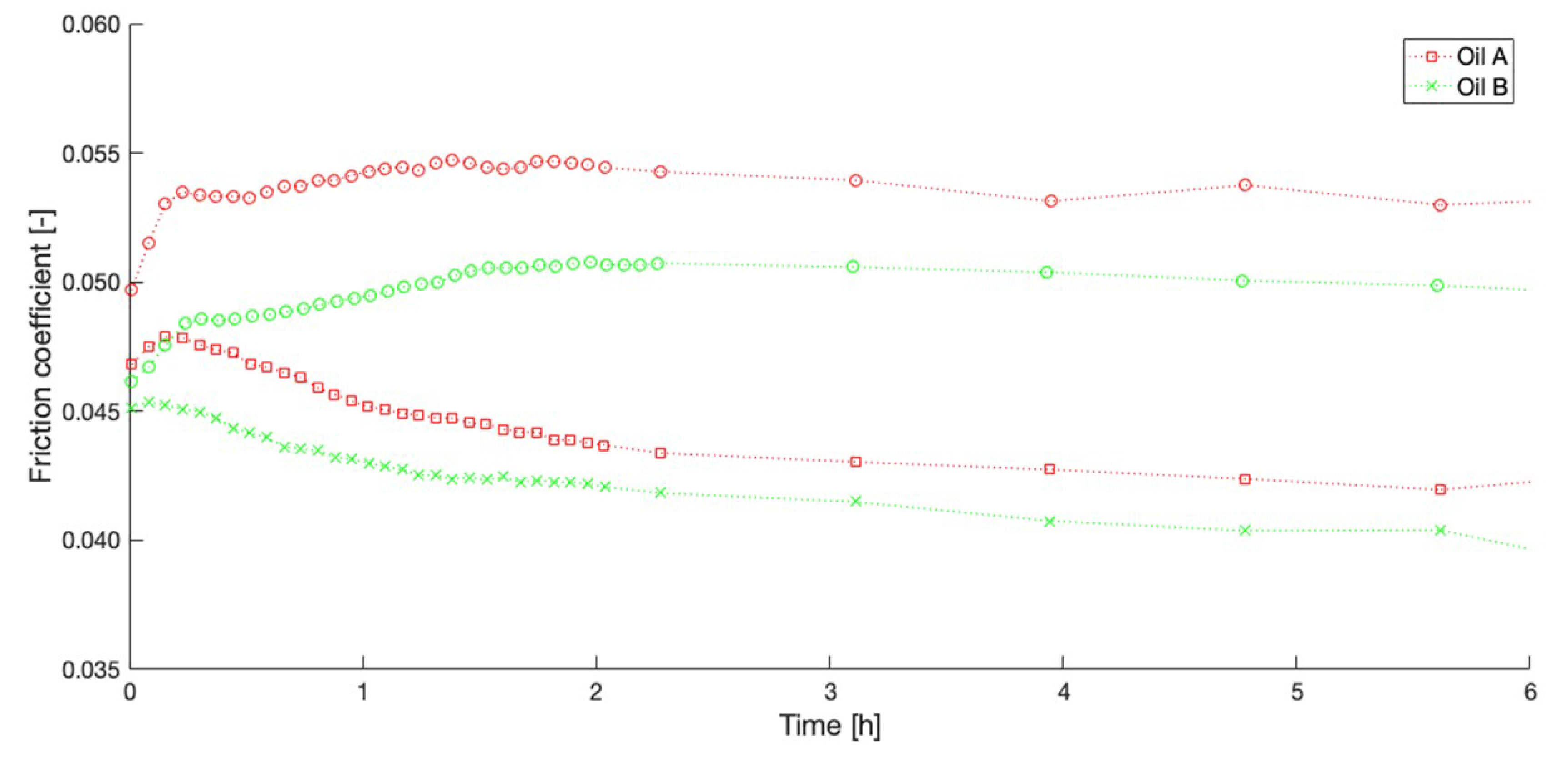
- The negative sliding reduces the micro-pitting tendency by increasing friction and wear compared to positive sliding.
Author Contributions
Funding
Acknowledgments
Conflicts of Interest
References
- Holmberg, K.; Andersson, P.; Erdemir, A. Global energy consumption due to friction in passenger cars. Tribol. Int. 2012, 47, 221–234. [Google Scholar] [CrossRef]
- Baubet, Y.; Pisani, C.; Carden, P.; Molenaar, L.; Reedman, A. Rolling Elements Assessment on Crankshaft Main Bearings of Light Duty Diesel Engine. Sae Int. J. Engines 2014, 7, 1401–1413. [Google Scholar] [CrossRef]
- Tiemann, C.; Orlowsky, K.; Steffens, C.; Bick, W.; Kalenborn, M. The roller bearing engine—A cost effective contribution to CO2 reduction. In Proceedings of the Spring Technical Conference of the ASME Internal Combustion Engine Division, Aachen, Germany, 7–10 May 2006. [Google Scholar]
- Tiemann, C.; Kalenborn, M.; Orlowsky, K.; Steffens, C.; Bick, W. An effective way to the consumption reduction of rolling bearing in the internal combustion engine|Ein effektiver Weg zur Verbrauchsreduktion Wälzlagerung im Verbrennungsmotor. MTZ Mot. Z. 2007, 68, 286–293. [Google Scholar] [CrossRef]
- Rycerz, P.; Olver, A.; Kadiric, A. Propagation of surface initiated rolling contact fatigue cracks in bearing steel. Int. J. Fatigue 2017, 97, 29–38. [Google Scholar] [CrossRef] [Green Version]
- Vrcek, A.; Hultqvist, T.; Baubet, Y.; Björling, M.; Marklund, P.; Larsson, R. Micro-pitting and wear assessment of engine oils operating under boundary lubrication conditions. Tribol. Int. 2019, 129, 338–346. [Google Scholar] [CrossRef]
- Benyajat, C.; Olver, A.V. The Effect of a ZnDTP Anti-Wear Additive on the Micropitting Resistance of Carburised Steel Rollers; AGMA Tech. Pap.; American Gear Manufacturers Association (AGMA): Alexandria, VA, USA, 2004. [Google Scholar]
- Laine, E.; Olver, A.; Beveridge, T. Effect of lubricants on micropitting and wear. Tribol. Int. 2008, 41, 1049–1055. [Google Scholar] [CrossRef]
- Laine, E.; Olver, A.V.; Lekstrom, M.F.; Shollock, B.A.; Beveridge, T.A.; Hua, D.Y. The Effect of a Friction Modifier Additive on Micropitting. Tribol. Trans. 2009, 52, 526–533. [Google Scholar] [CrossRef]
- Brizmer, V.; Pasaribu, H.R.; Morales-Espejel, G.E. Micropitting Performance of Oil Additives in Lubricated Rolling Contacts. Tribol. Trans. 2013, 56, 739–748. [Google Scholar] [CrossRef]
- Brizmer, V.; Matta, C.; Nedelcu, I.; Morales-Espejel, G.E. The Influence of Tribolayer Formation on Tribological Performance of Rolling/Sliding Contacts. Tribol. Lett. 2017, 65, 815. [Google Scholar] [CrossRef]
- Shimizu, Y.; Spikes, H.A. The Influence of Slide–Roll Ratio on ZDDP Tribofilm Formation. Tribol. Lett. 2016, 64, 1–11. [Google Scholar] [CrossRef]
- Cen, H.; Morina, A.; Neville, A. Effect of slide to roll ratio on the micropitting behaviour in rolling-sliding contacts lubricated with ZDDP-containing lubricants. Tribol. Int. 2018, 122, 210–217. [Google Scholar] [CrossRef]
- Suarez, A.N.; Grahn, M.; Pasaribu, R.; Larsson, R. The influence of base oil polarity on the tribological performance of zinc dialkyl dithiophospate additives. Tribol. Int. 2010, 43, 2268–2278. [Google Scholar] [CrossRef]
- Naveira-Suarez, A.; Tomala, A.; Grahn, M.; Zaccheddu, M.; Pasaribu, R.; Larsson, R. The influence of base oil polarity and slide–roll ratio on additive-derived reaction layer formation. Proc. Inst. Mech. Eng. Part J J. Eng. Tribol. 2011, 225, 565–576. [Google Scholar] [CrossRef]
- Taylor, L.J.; Spikes, H.A. Friction-Enhancing Properties of ZDDP Antiwear Additive: Part I—Friction and Morphology of ZDDP Reaction Films. Tribol. Trans. 2003, 46, 303–309. [Google Scholar] [CrossRef]
- Fujita, H.; Spikes, H.A. The formation of zinc dithiophosphate antiwear films. Proc. Inst. Mech. Eng. Part J J. Eng. Tribol. 2004, 218, 265–278. [Google Scholar] [CrossRef]
- Fujita, H.; Spikes, H.A. Study of Zinc Dialkyldithiophosphate Antiwear Film Formation and Removal Processes, Part II: Kinetic Model. Tribol. Trans. 2005, 48, 567–575. [Google Scholar] [CrossRef]
- Rabaso, P.; Gauthier, T.; Diaby, M.; Ville, F. Rolling Contact Fatigue: Experimental Study of the Influence of Sliding, Load, and Material Properties on the Resistance to Micropitting of Steel Discs. Tribol. Trans. 2013, 56, 203–214. [Google Scholar] [CrossRef]
- Morales-Espejel, G.E.; Brizmer, V. Micropitting Modelling in Rolling–Sliding Contacts: Application to Rolling Bearings. Tribol. Trans. 2011, 54, 625–643. [Google Scholar] [CrossRef]
- Morales-Espejel, G.E.; Rycerz, P.; Kadiric, A. Prediction of micropitting damage in gear teeth contacts considering the concurrent effects of surface fatigue and mild wear. Wear 2017, 398–399, 99–115. [Google Scholar] [CrossRef]
- Hultqvist, T.; Shirzadegan, M.; Vrcek, A.; Baubet, Y.; Prakash, B.; Marklund, P.; Larsson, R. Elastohydrodynamic lubrication for the finite line contact under transient loading conditions. Tribol. Int. 2018, 127, 489–499. [Google Scholar] [CrossRef]
- Hultqvist, T.; Vrcek, A.; Prakash, B.; Marklund, P.; Larsson, R. Influence of Lubricant Pressure Response on Subsurface Stress in Elastohydrodynamically Lubricated Finite Line Contacts. J. Tribol. 2018, 141, 031502. [Google Scholar] [CrossRef]
- Olver, A.V.; Macpherson, P.B.; Spikes, H.A. Wear in rolling contacts. Wear 1986, 112, 121–144. [Google Scholar]
- Johansson, J.E.; Devlin, M.T.; Guevremont, J.M.; Prakash, B. Effects of Gear Oil Properties on Pitting Life in Rolling Four-Ball Test Configuration. Tribol. Trans. 2013, 57, 104–113. [Google Scholar] [CrossRef]
- Hamrock, B.J.; Dowson, D. Isothermal Elastohydrodynamic Lubrication of Point Contacts Part 1—Theoretical Formulation The. J. Lubr. Technol. 1976, 99, 223–228. [Google Scholar] [CrossRef]
- Van Leeuwen, H. The determination of the pressure–viscosity coefficient of a lubricant through an accurate film thickness formula and accurate film thickness measurements. Part 2: High L values. Proc. Inst. Mech. Eng. Part J J. Eng. Tribol. 2011, 225, 449–464. [Google Scholar] [CrossRef]
- Venner, C.H.; Lubrecht, A.A. Amplitude Reduction of Non-Isotropic Harmonic Patterns in Circular EHL Contacts, under Pure Rolling. Tribol. Ser. 1998, 34, 151–162. [Google Scholar]
- Morales-Espejel, G.E. Surface roughness effects in elastohydrodynamic lubrication: A review with contributions. Proc. Inst. Mech. Eng. Part J J. Eng. Tribol. 2014, 228, 1217–1242. [Google Scholar] [CrossRef]


| Designation | SAPS 1 Level | Viscosity Grade | Kinematic Viscosity 2 at 100 °C [cst] | Description |
|---|---|---|---|---|
| Oil A 0W20 | Mid | 0W20 | 8.1 | Standard production engine oil |
| Oil B 0W20 RC | Mid | 0W20 | 7.7 | Optimized for rolling contacts |
| Specimens | Roughness Lay | Roughness, Rq [nm] | Hardness, HRC |
|---|---|---|---|
| Ball | Isotropic | 25 ± 5 | 66 |
| Disc 1 | Transverse 1 | 250 ± 15 | 66 |
| Disc 2 | Longitudinal 1 | 300 ± 15 | 66 |
| Testing Conditions | Values |
|---|---|
| Maximum contact pressure, Pmax [GPa] | 2.0 |
| Slide-to-roll ratio, SRR [%] | +5, −5 |
| Lambda ratio, | 0.15, 0.40 and 0.80 |
| Entrainment speed, ve [m/s] for T/L 1 | |
| 1.00/1.26 | |
| 4.00/5.30 | |
| 11.22/- | |
| Surface temperature of the disc, Ts [°C] | 100 |
| Numbers of cycles for ball | 4.4 million 2 |
| Test Number | Oil | Lambda | SRR | Roughness Lay | Track Diameter [mm] |
|---|---|---|---|---|---|
| 1 | A | 0.15 | +5 | Transverse | 79 |
| 2 | B | 0.15 | +5 | Transverse | 70 |
| 3 | B | 0.15 | +5 | Transverse | 97 |
| 4 | A | 0.8 | +5 | Transverse | 79 |
| 5 | B | 0.8 | +5 | Transverse | 70 |
| 6 | A | 0.8 | -5 | Transverse | 76 |
| 7 | B | 0.8 | -5 | Transverse | 73 |
| 8 | A | 0.4 | +5 | Transverse | 67 |
| 9 | B | 0.4 | +5 | Transverse | 64 |
| 10 | B | 0.4 | +5 | Longitudinal | 64 |
| 11 | A | 0.4 | +5 | Longitudinal | 67 |
| 12 | B | 0.15 | +5 | Longitudinal | 76 |
| 13 | A | 0.15 | +5 | Longitudinal | 79 |
| SRR | Rev Ball | Rev Disc | Sliding Distance [m] |
|---|---|---|---|
| +5 | 4.4 millions | 1.0 millions | 13,478 |
| −5 | 4.2 millions | 1.2 millions | 13,478 |
© 2019 by the authors. Licensee MDPI, Basel, Switzerland. This article is an open access article distributed under the terms and conditions of the Creative Commons Attribution (CC BY) license (http://creativecommons.org/licenses/by/4.0/).
Share and Cite
Vrček, A.; Hultqvist, T.; Baubet, Y.; Björling, M.; Marklund, P.; Larsson, R. Micro-Pitting and Wear Assessment of PAO vs Mineral-Based Engine Oil Operating under Mixed Lubrication Conditions: Effects of Lambda, Roughness Lay and Sliding Direction. Lubricants 2019, 7, 42. https://doi.org/10.3390/lubricants7050042
Vrček A, Hultqvist T, Baubet Y, Björling M, Marklund P, Larsson R. Micro-Pitting and Wear Assessment of PAO vs Mineral-Based Engine Oil Operating under Mixed Lubrication Conditions: Effects of Lambda, Roughness Lay and Sliding Direction. Lubricants. 2019; 7(5):42. https://doi.org/10.3390/lubricants7050042
Chicago/Turabian StyleVrček, Aleks, Tobias Hultqvist, Yannick Baubet, Marcus Björling, Pär Marklund, and Roland Larsson. 2019. "Micro-Pitting and Wear Assessment of PAO vs Mineral-Based Engine Oil Operating under Mixed Lubrication Conditions: Effects of Lambda, Roughness Lay and Sliding Direction" Lubricants 7, no. 5: 42. https://doi.org/10.3390/lubricants7050042