The Influence of Surface Texturing on the Film Thickness in Starved Lubricated Parallel Sliding Contacts


1
Materials Innovation Institute (M2i), P.O. Box 5008, 2600 GA Delft, The Netherland
2
Bosch Transmission Technology, Dr. Hub Van Doorneweg 120, 5026 RA Tilburg, The Netherlands
3
Laboratory for Surface Technology and Tribology, Faculty of Engineering Technology, University of Twente, P.O. Box 217, 7500 AE Enschede, The Netherlands
*
Author to whom correspondence should be addressed.
Lubricants 2018, 6(3), 61; https://doi.org/10.3390/lubricants6030061
Submission received: 27 May 2018
/
Revised: 3 July 2018
/
Accepted: 4 July 2018
/
Published: 11 July 2018
(This article belongs to the Special Issue Tribological Performance of Textured Surfaces)
Abstract
:In industrial applications, a starved lubrication condition may occur, leading to a reduction in film thickness; by modifying the surface geometry, the tribological performance of the contact is enhanced. In this paper, the influence of surface texturing as a method for reducing the friction on the film thickness in parallel sliding surfaces for starved lubricated contacts is investigated. The results in this study have shown that surface texturing can improve film formation for starved lubricated contacts and, respectively, the load carrying capacity. The effect of starvation on several texturing patterns with several texturing properties was investigated and the film thickness for these conditions was studied. With the numerical algorithm developed and taking cavitation into consideration, the effect of shape, depth, size, and texture pitch on the film thickness was studied.
1. Introduction
The prediction of the lubricant film thickness between lubricated surfaces has been the focus of attention for decades. Some of the parameters affecting the film thickness are velocity, load, lubricant viscosity, and contact geometry. All of the aforementioned parameters have their own effect on the film thickness. The study of starved lubrication—i.e., when a limited amount of lubricant is supplied to the contact—has attracted tribologists for many years. For example, this growing interest in starvation has shown a high probability of lubricant starvation in the contacts of high-speed bearings. It is observed that the starvation can have a significant effect on the lubricant’s film formation and that the film thickness generated by the existence of the lubricant will be severely limited due to the starvation. Frequently, the lubricant cannot ensure a full separation of the two surfaces, which leads to higher friction. It is known that by applying a texture, the tribological properties of the mechanical components can be enhanced. This technique has been employed in the past decades as a well-known option for improving the load carrying capacity and wear resistance, and for reducing the friction coefficient of lubricated systems. By optimizing the texture dimensions, it is possible to retain lubricant and improve the hydrodynamic effect [1,2,3,4,5,6,7,8,9].
Starved lubrication has been experimentally investigated by several authors, such as Wedeven et al. [10], Pemberton et al. [11], and Kingsbury [12]. Further, Chiu [13] and Chevalier et al. [14], followed by Damiens et al. [15], have theoretically studied starved lubrication. These theoretical studies were based on the work of Jakobsson and Floberg [16] and Olsson [17], who introduced the concept of “fractional film content” and derived continuity relations.
The influence of starvation on the lubrication of rigid cylinders was studied by Floberg [18]. Dalmaz and Godet [19] studied the influence of inlet starvation on the reduction in film thickness in the case of a sphere against a lubricated plate. In the work of Brewe and Hamrock [20], the influence of starvation was studied theoretically. In this work, by using the Reynolds boundary condition and by systematically reducing the fluid inlet level, they observed the pressure buildup for a given film thickness. In their study, the inlet meniscus boundary was taken as the start of the pressure buildup. They analyzed a wide range of geometry parameters from a ball on a plate to a ball in a conforming groove. Moreover, for a fully flooded conjunction, the film thickness formula was modified to incorporate the starvation effect into it. Bonessmicro [21] experimentally showed the importance of the starvation effects on the bearing failure and wear. Chevalier et al. [22] used a numerical hydrodynamic analysis. They studied the effect of repeated passes on the film thickness with a constant and harmonic oil inlet. In their study, they employed the work of Elrod et al. [23,24] and showed that the shape of the oil inlet film could influence film thickness behavior. Cann and Lubrecht [25] further studied the properties of the lubricant and four variable parameters—oil volume, velocity, load, and viscosity—and the influence of each parameter on lubricant film thickness. In their work, they presented the film thickness for a wide range of velocities and different lubricant parameters.
For fully flooded (elasto-) hydrodynamic lubrication, micro-geometric cavities have been successfully used to improve the lubrication between surfaces. These micro-scale cavities can increase the film thickness and the load carrying capacity, can entrap wear debris, and can act as micro-reservoirs; see for instance Etsion et al. [2,5,6]. Surface texturing also influences the transitions between the lubrication regimes [7], i.e., the lubrication regime transformation between full film, mixed, and boundary lubrication.
In the work of Ryk et al. [9], the possible advantages of applying laser surface texturing (LST) to piston rings have been demonstrated theoretically and experimentally. By employing the full LST rings, the optimum texturing parameters, in the case of the minimum friction force, were found. Their work found good agreement with experimental results. Their results revealed the benefits of surface texturing in full lubrication conditions, as well as starved lubrication conditions. Based on this study, in an internal combustion engine application, the employment of micro-grooves in cylinder liners show lower fuel consumption and wear. The textured surfaces provide a thicker lubricant film than the non-textured surfaces in which the grooves act as local Rayleigh step bearings. Experimental measurements showed that due to texturing, the textured bearing can generate a lubricant film about three times thicker than the film thickness of the non-textured bearing throughout the range of the tested loads. In this paper, the effect of texturing (meso-geometry), including cavitation, on the lubricant film characteristics was studied for macroscopically starved lubricated plane-parallel sliding surfaces. The surfaces were smooth, i.e., no roughness (micro-geometry).
2. Materials and Methods
Osborne Reynolds in 1886 derived a partial differential equation to calculate the pressure buildup in self-acting bearings. This equation has been used successfully to explain the fluid film pressure distribution in lubricated contacts. This equation can be deduced from the Navier–Stokes equations under the narrow gap assumption that the Reynolds number of the fluid flow in the gap between the surfaces is small. The Reynolds equation in Cartesian coordinates can be written as Equation (1):
In this equation, is the film thickness, is the viscosity, is the sum velocity, and is the density of the lubricant. In sliding direction at the outlet of the cavity, the lubricant is dragged through a converging region and, as a result, pressure is generated. At the opening of the cavity, the flow diverges, which, according to the Reynolds equation (Equation (1)), results in a negative pressure. However, a negative pressure is suppressed by the lubricant.
In the case of lubricated systems under a moderate load, the Jakobsson–Floberg–Olsson (JFO) [16,17] cavitation theory is used. It is not suitable for cases where surface tension plays an important role, such as in face seals [26]. Based on the Jakobsson–Floberg-Olsson theory, in lubricated contacts when cavitation is present, there are two zones of lubrication. In the first zone the lubricant film is complete, and the pressure varies in this region, therefore the Reynolds equation is applicable. In the second zone, due to the cavitation existence, only a fraction of the lubricant film gap is occupied by the lubricant film. The pressure within the cavitation area is taken as constant [26].
According to the Payvar–Salant [27,28] model, the steady-state mass-conservation Reynolds equation, taking cavitation into account, in a Cartesian coordinate system can be written as Equation (2) [29]:
In the above equation, is the ambient pressure, is the cavitation pressure, is a dimensionless dependent variable, and is the cavitation index. For more information, see Xiong and Wang [29].
Dobrica et al. [30] carried out an investigation based on the influence of cavitation and different texturing parameters on the hydrodynamic performance of textured surfaces. Their numerical study was based on the Reynolds equation with the JFO formulation on the plane-parallel contact and the sliding inclined contact. Their calculations focused on finding the optimum dimensions of the textured region and dimple aspect ratio. In their investigation on the plane-parallel textured sliding contacts, due to the cavitation, a significant influence on the performance is observed. The existence of cavitation in partially textured parallel sliders has a positive effect due to the increase of inlet flow (inlet suction). Furthermore, in convergent sliders with a high incline ratio, texturing shows a minimal effect, as well as cavitation. In this study, for different plane-inclined sliders, the optimal dimple depth and length were determined.
Mathematical Solution
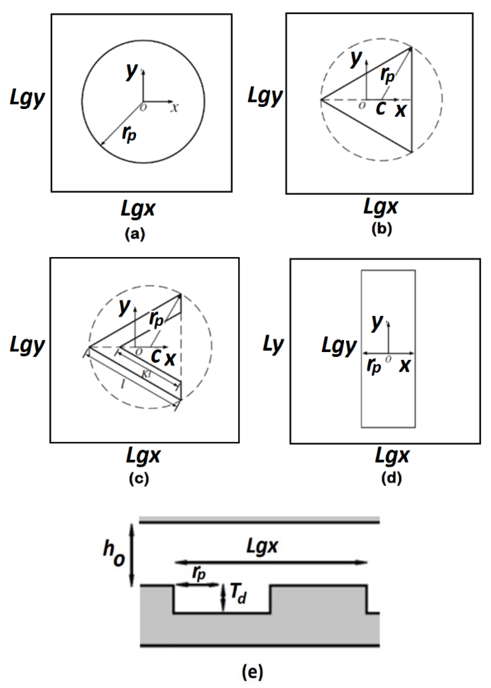
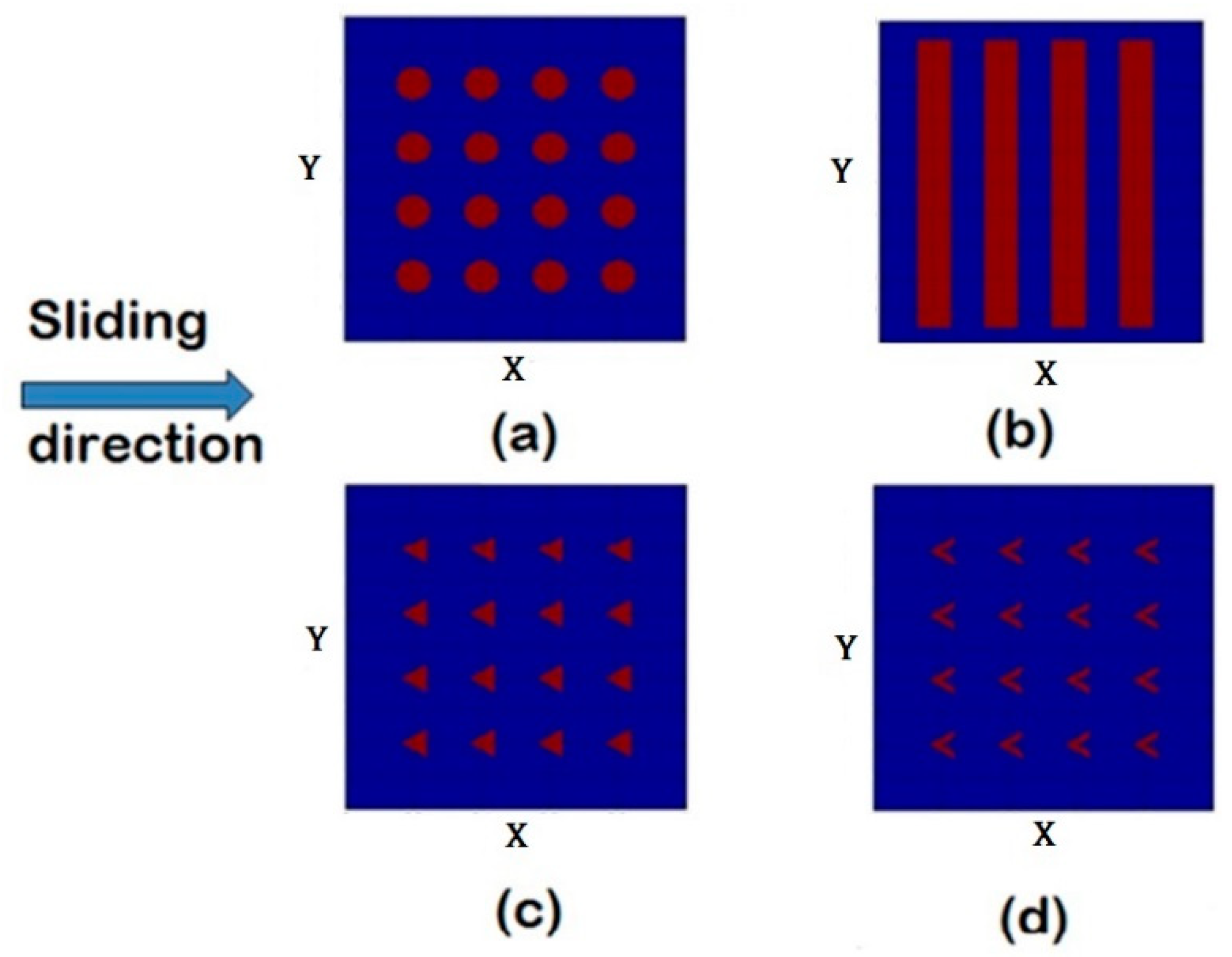
Four different texture patterns have been investigated: circular pocket, triangular pocket, chevron, and groove. Figure 1 shows the different cavity shapes and the parameters characterizing their geometries. The chevron pattern is defined by two similar equilateral triangles of different sizes. The triangular pocket is a special case of the chevron with the inner edge length of the chevron equal to zero. For these two cases, the center of the unit cell coincides with the midpoint of the altitude line of the triangle or chevron shape; see also [31]. All patterns investigated in this study had a rectangular cross-sectional profile. The general film gap can be formulated as Equation (3):
In the case of flat-flat contact, the macro geometry is omitted and Equation (3) reduces to Equation (4) [31,32]:
The formula for the circular pocket is given in Equation (5):
where and . The film thickness formula for the triangular pocket can be written as Equation (6):
The formula for the chevron can be written as Equation (7):
The formula for the grooves is given in Equation (8):
For solving Equation (2), the tri-diagonal matrix algorithm (TDMA) is used. Furthermore, to reduce the storage needed for calculation, the line-by-line TDMA solver (Patankar [33]) is applied. In the case of a two-dimensional problem, the TDMA becomes iterative, and sweeping is done line-by-line and column-by-column or row-by-row [34].
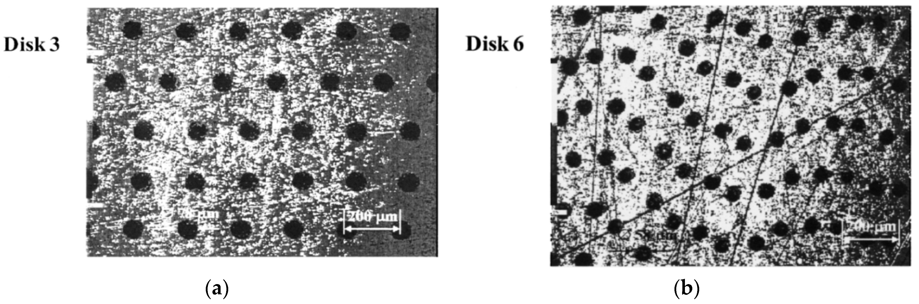
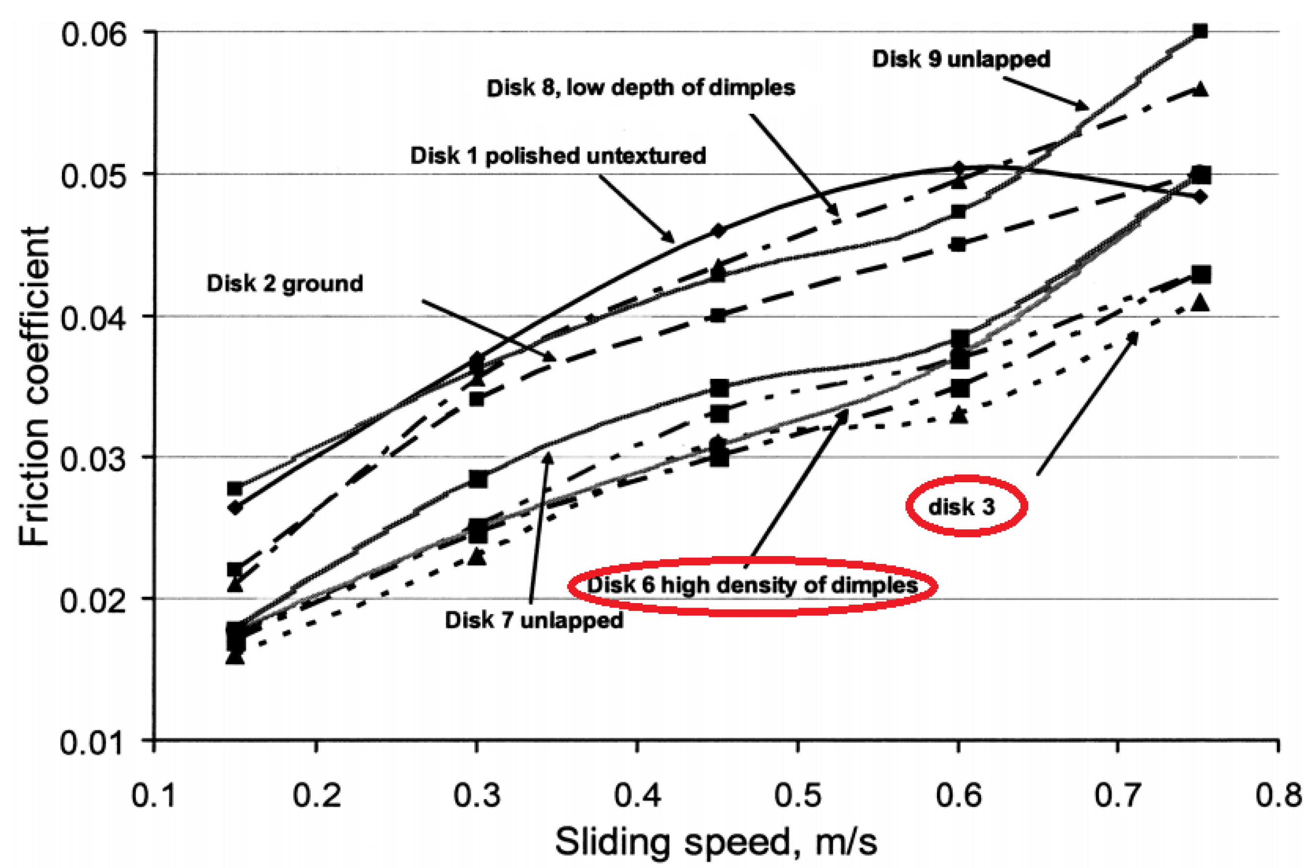
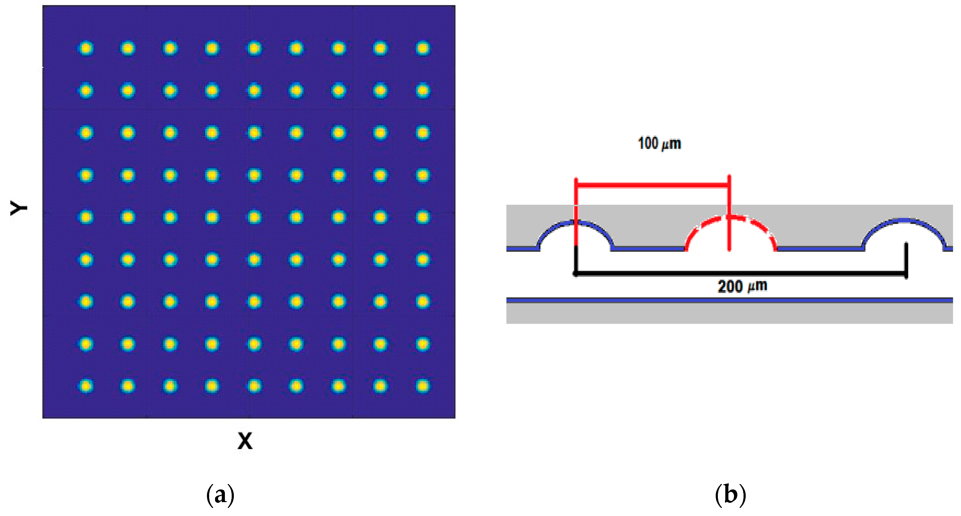
After developing the numerical code, the next step is to check the validity of the code. In this study, to validate the model and algorithm, a comparison was performed between the experimental measurements from the literature and the calculated results of this algorithm. In this validation, the experimental results were provided from the work of Kovalchenko et al. [35]. In their work, they investigated the effect of size and the density of dimples on the coefficient of friction. In Figure 2, two types of dimple arrays from this work are presented.
The geometrical properties of these two samples are presented in Table 1.
The measurement results for these two disks are presented in Figure 3.
From Figure 3 it is possible to extract the experimental data. Further, by using the numerical model for the full film non-starved condition when the lubricant kinematic viscosity is at , and by applying as the normal load, the hydrodynamic lubrication friction is calculated. The simulated texture array is presented in Figure 4.
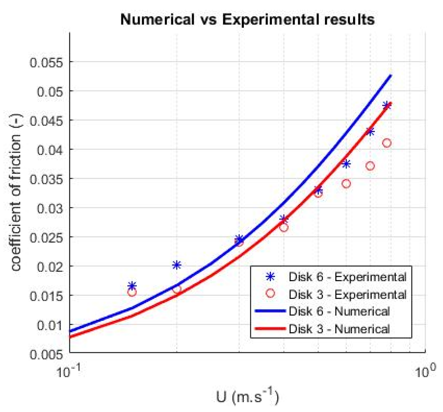
The comparison between the numerical results and experimental measurements for the abovementioned dimple types is presented in Figure 5.
From Figure 5, it is possible to see that there is a difference between the values of coefficient of friction calculated by the numerical model and experimentally measured results of this parameter. For example, when the velocity is , the calculated value is around 9% higher than the measured value for disk 6 and less than 1% for disk 3. This figure shows that the calculated coefficient of friction has almost the same trend and value as the measured coefficient of friction.
In this study, after the validation of the algorithm, several simulations were carried out to investigate the influence of starvation for textured surfaces with various texturing patterns and to investigate the film thickness behavior of the film thickness based on the different texturing parameters. The number and distance between the pockets are defined by introducing a new parameter, pitch. The pitch for the chevron, triangle, and circular pockets was calculated as follows:
Texture size =
Pitch in x direction: ; see Figure 1 for a definition of the geometry.
3. Results
Several simulations were performed in order to understand the effect of limited lubricant supply on the calculated film thickness for different texturing parameters for different patterns.
The film thickness obtained by texturing is under the influence of the limited amount of lubricant in the input region of the contact. By considering different values for the lubricant supply thickness , the effect of this parameter over the starved film thickness was calculated. Furthermore, the effect of texturing parameters—i.e., pattern type, texture pitch (), texture depth (), and texture size () on the starved film thickness ()—was studied. These simulations were based on surfaces with grooved, circular, triangular, and chevron pockets, presented in Figure 6.
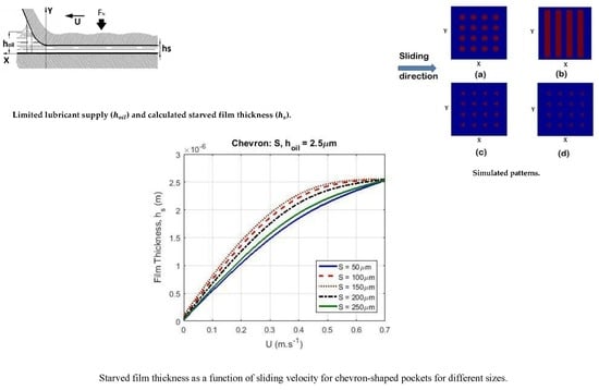
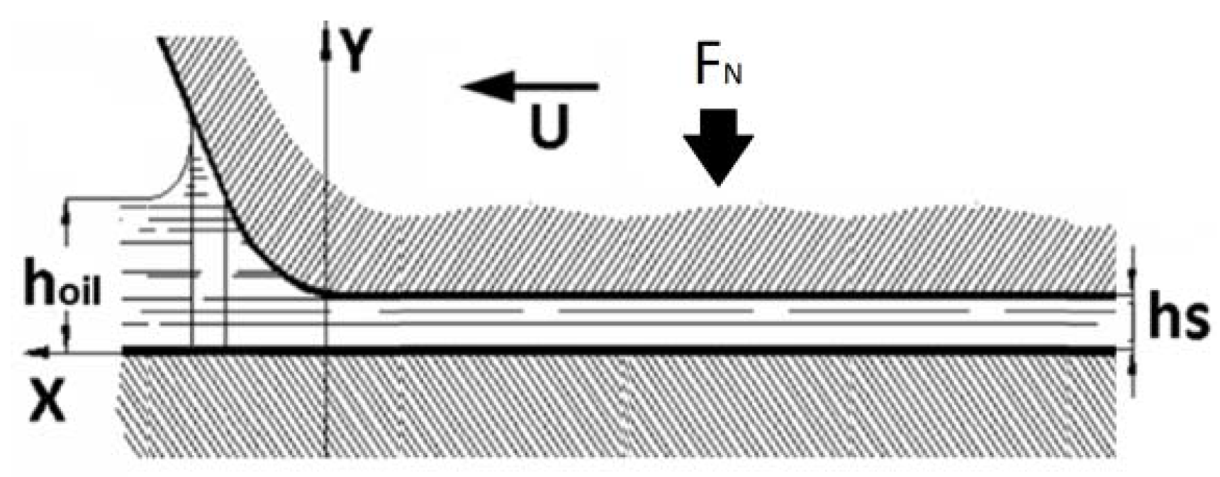
To study the effect of the value of lubricant supply thickness over different texturing patterns, was assumed to equal . In Figure 7, a schematic illustration of starved lubricated contact is presented.
When the texture pitch , texture size , and texture depth values were zero are close to zero, there was no film formation because of the absence of the wedge effect in flat-flat contact and the disappearance of texturing; therefore, there was no pressure generation. By increasing the values of , , and , textures appeared over the surface and pressure generation occurred in the contact due to the wedge effect. By increasing the texture depth and after passing the optimum value of this parameter, a higher depth resulted in a pressure drop due to the higher effect of cavitation. If the pitch value tends to a maximum value of itself—which is equal to one—then . That means that there was no texture on the surface of a flat-flat contact to build pressure at the contact. In the case of cavity size, after passed a specific value, the bigger size reduced the number of cavities until a single cavity existed over the surface. The existence of only one cavity would mean that there was only one outlet cavity wall against the lubricant flow. Therefore, larger cavity sizes can reduce the effect of texturing.
3.1. Grooves
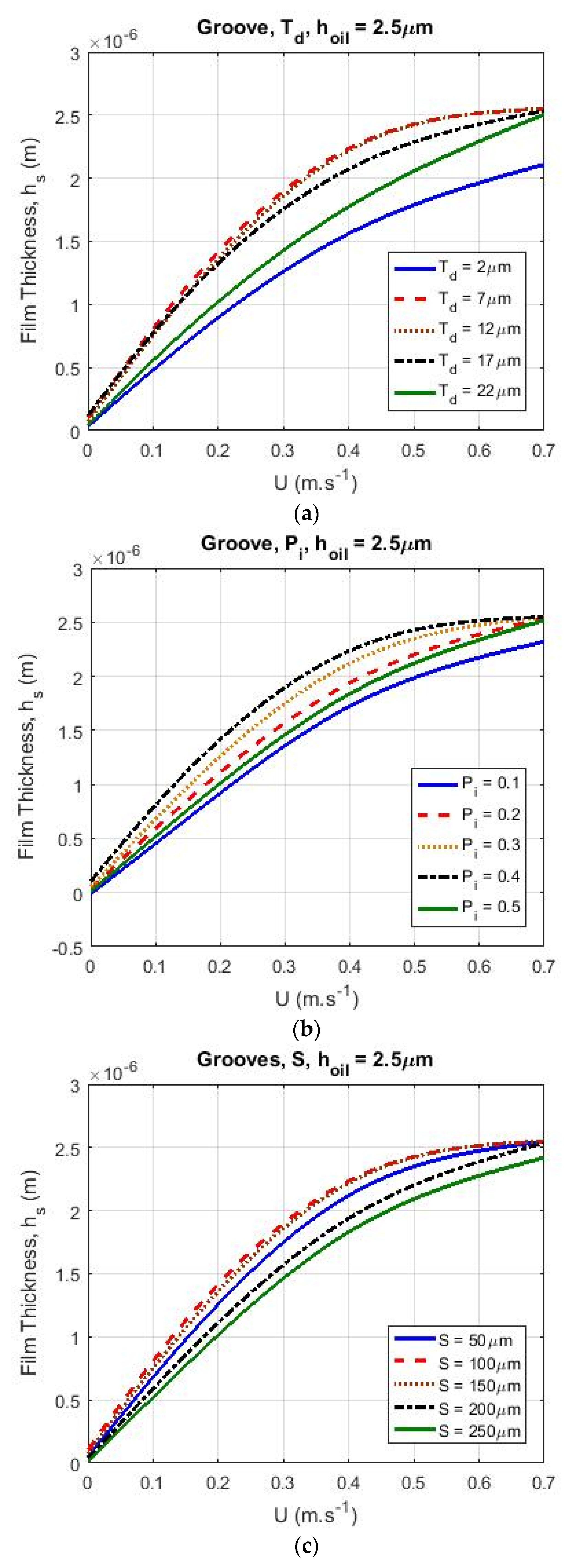
The film thickness obtained with a patterned, grooved surface with different values for and and is shown in Figure 8.
Figure 8a shows the effect of a limited lubricant supply on starved film thickness for different values of the texture depth parameter. When the sliding was in the lower velocity range [0 m s−1–0.3 m s−1], the film thickness was more sensitive to increasing texture depth than when the sliding velocity was in the higher velocity range [0.3 m s−1–0.7 m s−1]. In Figure 8b, when the contacts were sliding in the lower range of the velocity, the film thickness increased when was increased from to . However, after passing , there was a decrease in film thickness. The aforementioned effect of the variation of on the film thickness was sensitive when the surface sliding velocity was low. However, for higher velocities, the starvation effect had a greater influence on the film thickness. For high velocities, the film thickness was less sensitive to the pitch.
The influence of texture size () on the starved film thickness is shown in Figure 8c. From this calculation, it is shown that by increasing the velocity, the effect of employing the optimum values for texture size on film thickness was on the decrease and textures with different sizes had a tendency towards the same values of film thickness.
Figure 9 shows the film thickness for grooves. The effect of the lubricant supply on was studied for the geometry resulting in the highest film thickness. In this calculation, varied from to and , , and are shown.
In this paper, to compare the effect of the lubricant supply on different patterns, the same geometry that had been applied in Figure 9 (, and ) was utilized. In [36], the maximum film thickness was obtained for different patterns when the values for the texturing parameters were in the same range as those used in the calculations for Figure 9 (, , and ).
3.2. Dimples
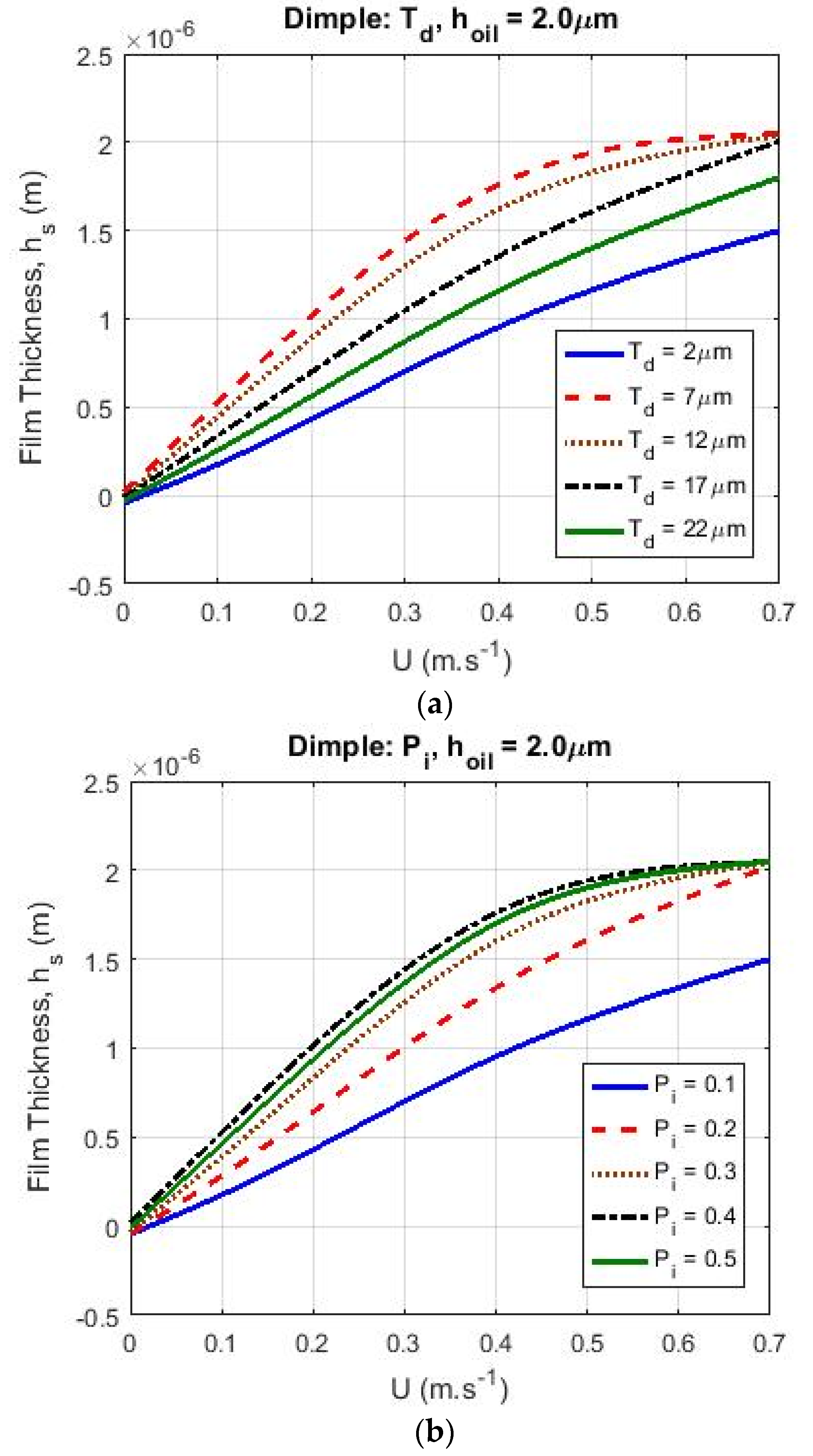
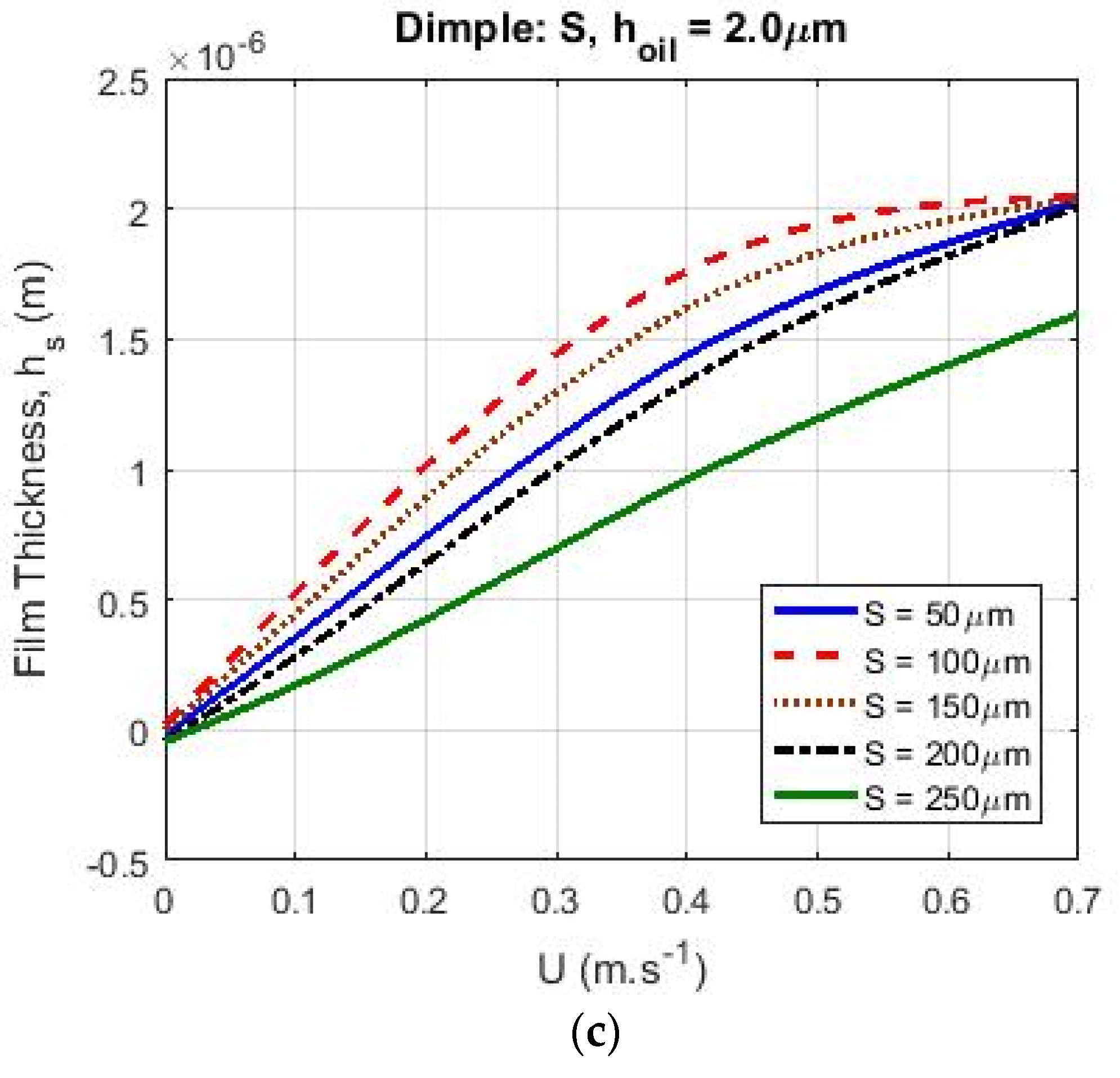
The effect of a fixed lubricant supply on for a circular pocket pattern was also studied. It is worth mentioning that by employing the circular pockets and the same operational conditions used for the other patterns, the maximum film thickness generated was around . Therefore, if the applied lubricant supply was similar to the other patterns (), then it would not be possible to observe a sensible effect of starvation on the film thickness behavior. To better understand the effect of starvation on film thickness for circular pockets, a lower amount of lubricant supply was applied (). The calculated film thickness for circular pockets (when , and ) is shown in Figure 10.
It was shown that the film thickness increased with the sliding velocity in the lower velocity range by increasing the texturing parameters (, and ) toward the optimum value. This effect of variation for different texturing properties on the film thickness was sensible when the surface sliding velocity was in the lower range of velocities [0–0.3 ] (Figure 10). However, at higher velocities [0.3 –0.7 ], the starvation effect exerted a greater influence on the film thickness. When the texturing parameter values were not too far from the optimum value of those parameters, at high velocities, the film thickness was less sensitive to the texture properties.
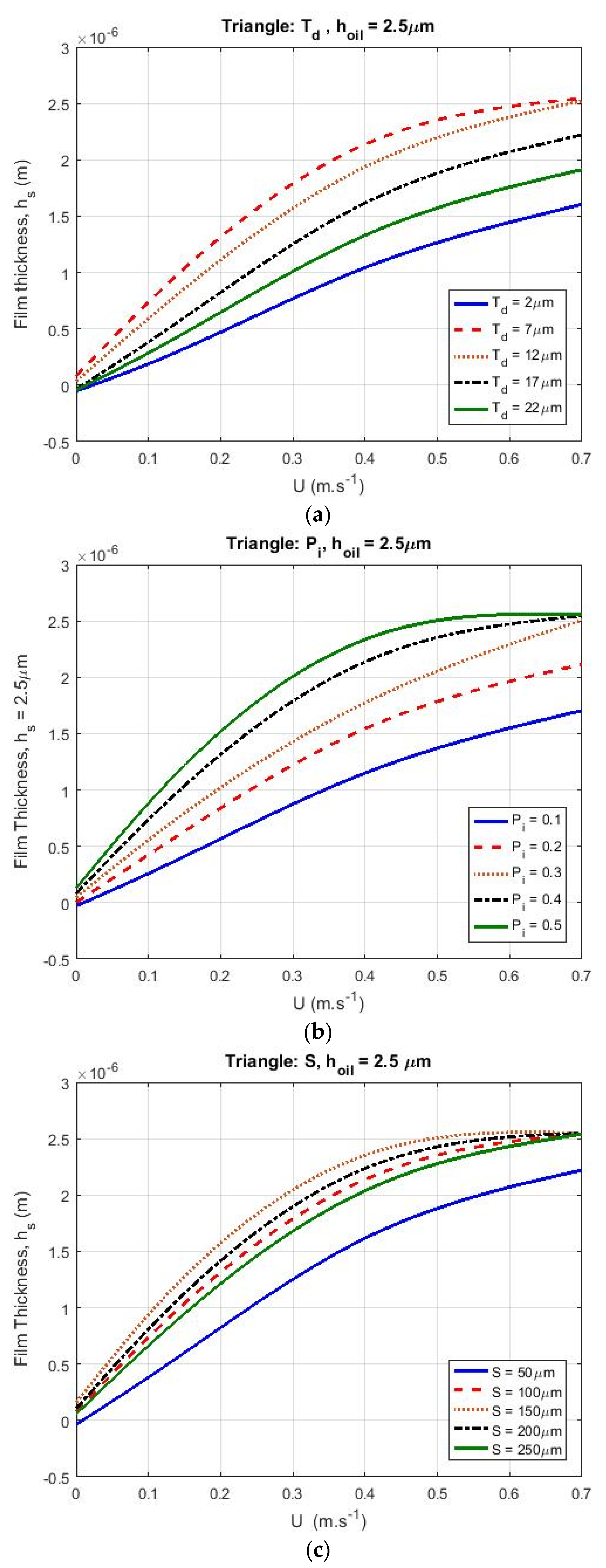
3.3. Triangular Pockets
The influence of different texturing parameters on starved film thickness for triangular pockets was investigated. The starved film thickness is presented in Figure 11; the calculations were based on .
For triangular pockets, as shown in Figure 11, the effect of variation in texturing parameters on the film thickness was similar to the calculations that were presented for the circular pockets. When the sliding velocity was low, by increasing the optimum value of the texturing parameters (, and ), the film thickness also increased. This effect of the variation of different texturing properties on film thickness was lower when the surface sliding velocity was higher.
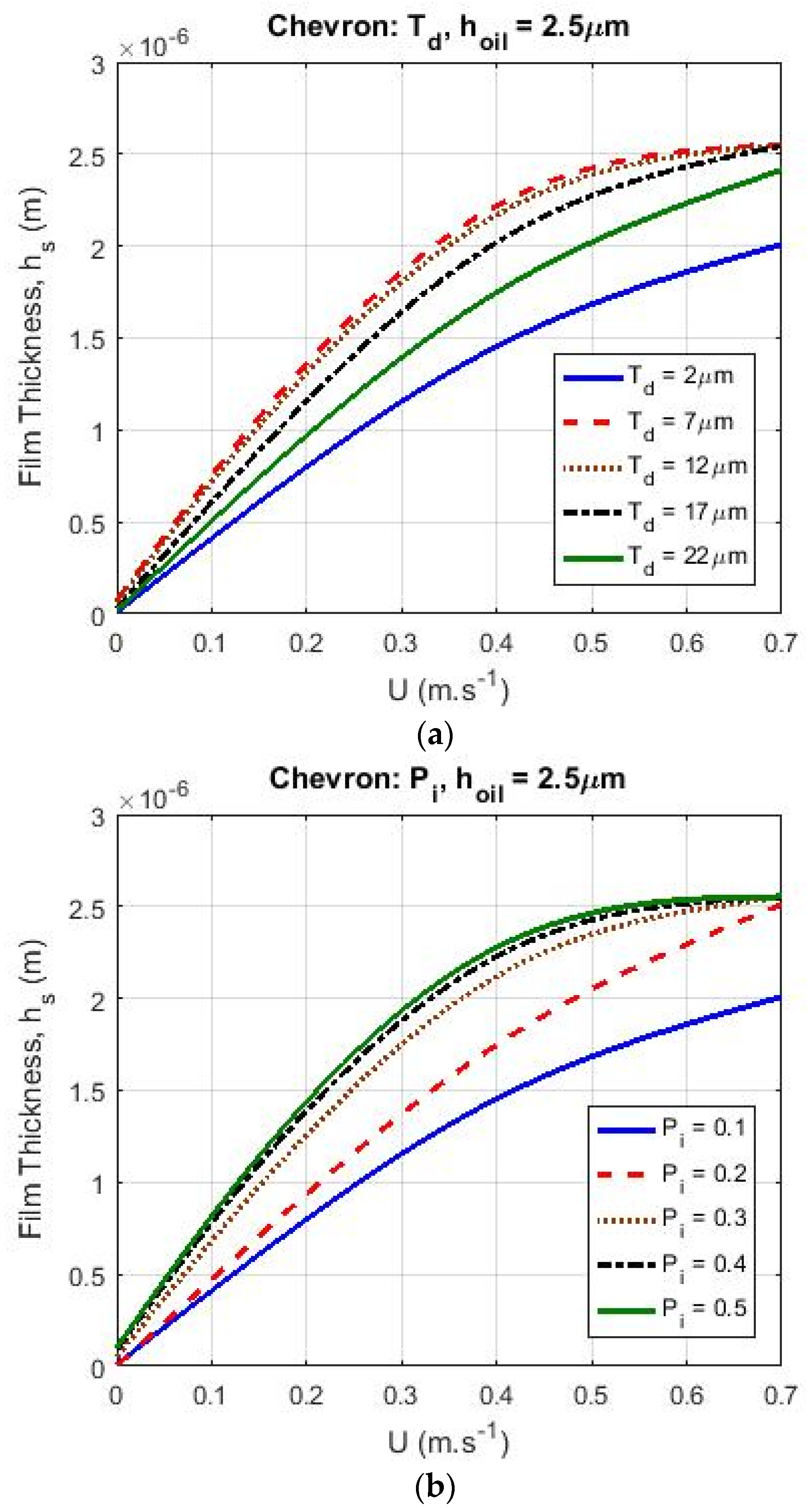
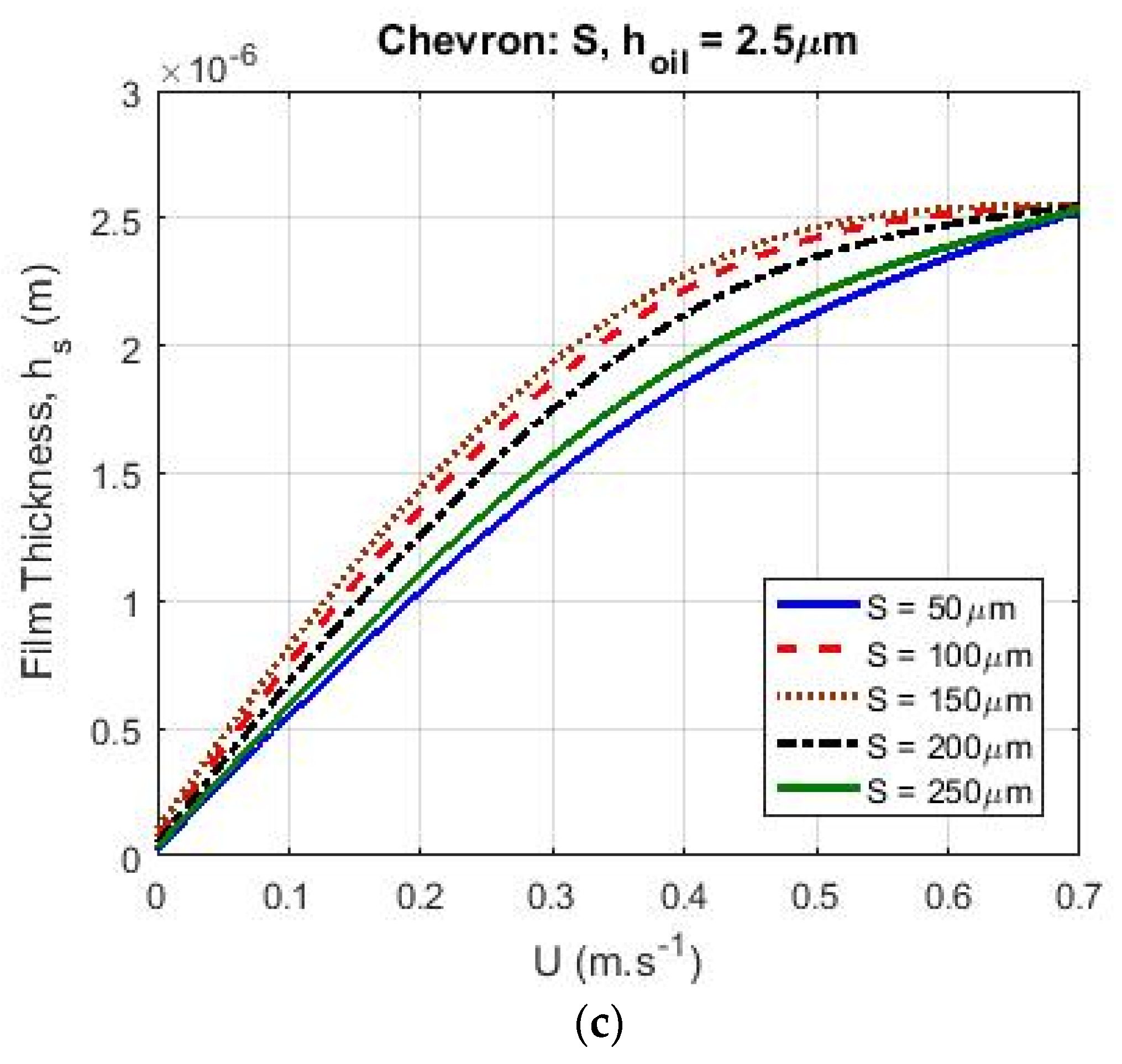
3.4. Chevrons
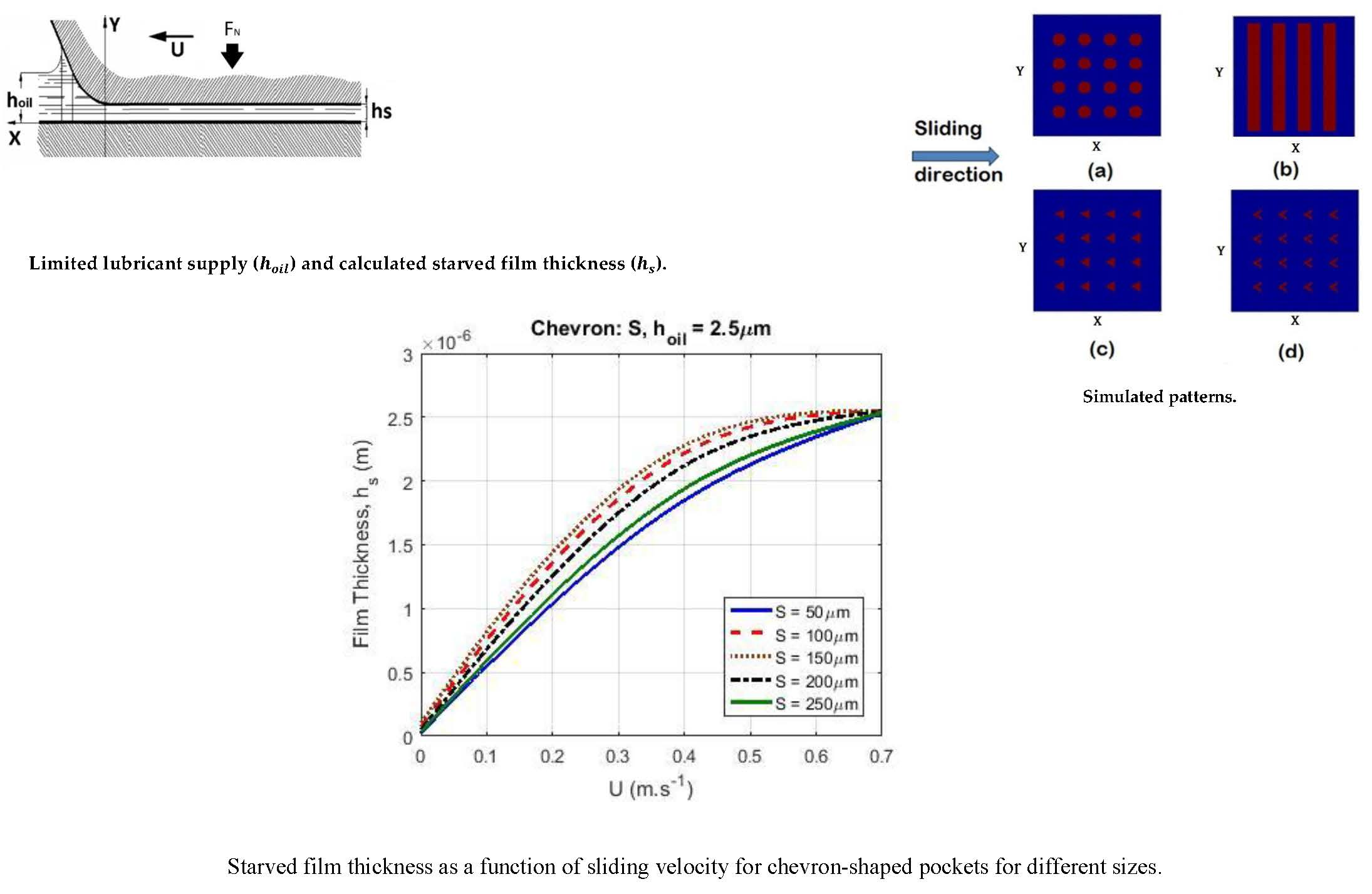
The effect of different texturing parameters on the starved film thickness in the case of chevron-shaped pocket patterns is presented in Figure 12, and these calculations were based on a lubricant supply .
In the case of chevron patterns (see Figure 12), the effect of variation of texturing parameters was similar to the previous calculations. The only difference was in the optimum values for the texturing properties.
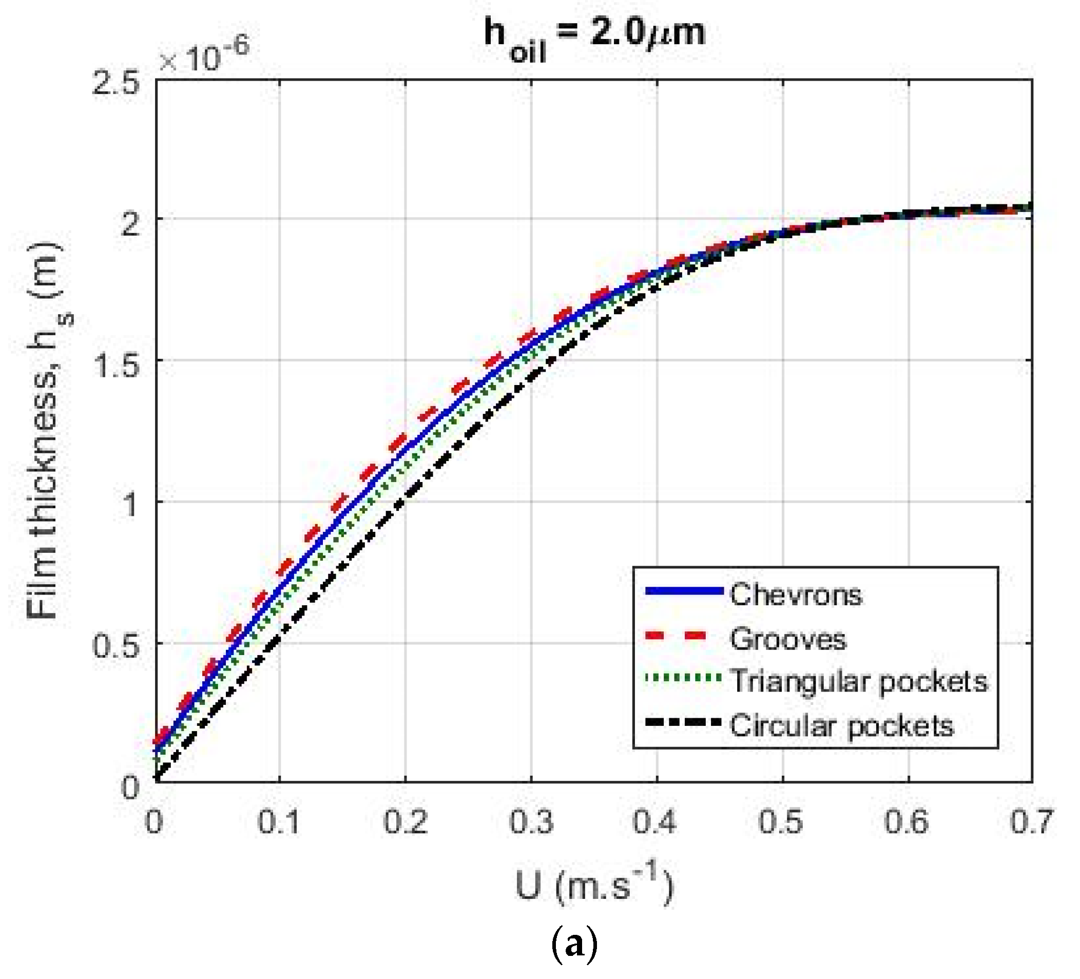
3.5. Comparison of Surface Patterns
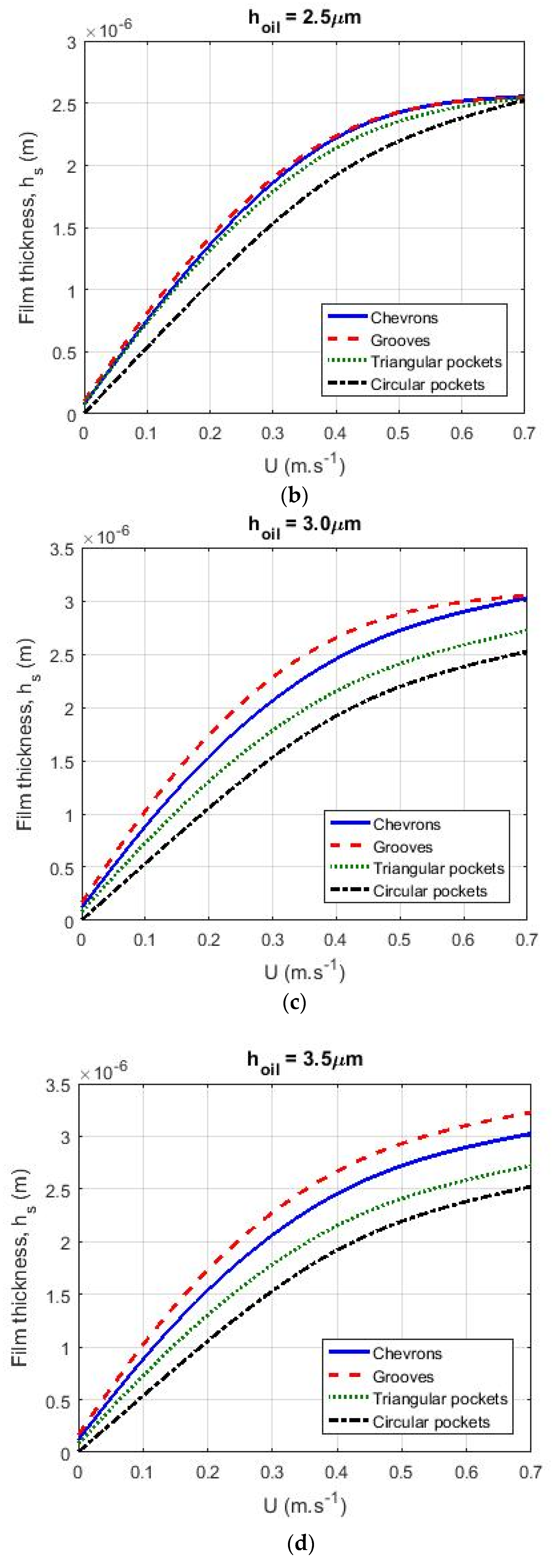
In Figure 13, film thickness as a function of velocity is shown for different patterns when , , and . In these calculations, the effect of different texture patterns as a function of was studied: and .
For different levels of lubricant supply ( the groove pattern had a promising effect for generating the highest film thickness for sliding velocities between and . The chevron pattern produced a thicker film compared to the triangular and circular pockets. Moreover, by employing the circular pocket pattern, the lowest film thickness was obtained. In Figure 13a, when was equal to , the effect of starvation on the calculated film thickness was higher. In this case, at higher velocities, the film thickness generated by different patterns had the same value.
By increasing , the effect of starvation on the film thickness decreased. For instance, when (see Figure 13d), the variation in film thickness based on different texturing patterns was achievable at high and low velocities, unlike for (Figure 13a) where at higher velocities there was no difference between the film thickness generated by the different patterns. In this case, the groove pattern had the most promising effect for gaining a higher film thickness.
When the distance between the texture cells were the same (pitch is constant), the groove pattern was more successful in generating load carrying capacity because of the higher textured area fraction per unit area. Chevrons were more efficient than triangular pockets and circular pockets because of the existence of a longer outlet wall in the cavity zone.
In summary, the results in Figure 13 show that the highest film thickness was achieved for the grooves and the lowest film thickness was found when circular pockets were applied. Compared to the triangular pockets, the chevrons were more efficient.
4. Conclusions
A numerical code has been developed to predict the lubricant film formation for textured surfaces for starved lubricated contacts. Simulations of textured surfaces with different patterns and different texture properties showed that the lubricant film thickness of such contacts could be adjusted to the desired situation with texture properties. The lubrication model was based on a numerical algorithm using the Reynolds equation with the Elrod cavitation algorithm formulation. The equations were made discrete using the finite difference method and solved using the TDMA iterative method. The effect of several parameters on the starved film thickness, such as pattern type, depth, size, and texture pitch, has been studied.
- Of the patterns analyzed, the groove pattern showed the highest lubricant film formation due to the higher textured area fraction of the surface.
- In the case of starved lubrication, increasing the dimensions of the texture parameters (, and ) resulted in increased film thickness at low velocities. After passing the optimum value of the texture parameters for different patterns, there was a decrease in film thickness. The aforementioned effect on film thickness was visible when the surface sliding velocity was low. At high velocities when the influence of geometry and the optimization of texturing parameters are more sensible, the starvation effect exerted a greater influence on the film thickness. It is worth mentioning that this sensitivity to the texturing parameters depended on the pattern type and operational conditions for different cases. Further, at velocities higher than , the film thickness was less sensitive to texture properties.
- For different lubricant supply values , the groove pattern showed the highest film thickness at low velocities. The chevron pattern generated a larger film thickness than the triangular and circular pockets and the lowest film thickness was found for the circular pocket pattern.
- For small values of , the effect of starvation on calculated film thickness was higher. For high velocities, the generated film thickness in this case for the different patterns was the same.
- By increasing the lubricant supply (), the texturing pattern geometry had a larger influence on the generated film thickness, while starvation reduced the effect of the texture on the film thickness.
Author Contributions
Conceptualization, D.J.S., E.L.D. and D.B.; Methodology, D.J.S. and D.B.; Software, D.B.; Validation, D.B. and D.J.S.; Formal Analysis, D.B. and D.J.S.; Investigation, D.B. and D.J.S.; Writing-Original Draft Preparation, D.B.; Writing-Review & Editing, D.B., E.L.D., M.B.d.R. and D.J.S.; Supervision, D.J.S.
Funding
This research was funded by Materials Innovation Institute (M2i) grant number M21.1.11448.
Acknowledgments
The authors would like to gratefully acknowledge Nilgoon Irani for her help on writing this article.
Conflicts of Interest
The authors declare no conflict of interest.
Nomenclature
| Parameters | Description | Unit |
| film thickness | ||
| contact separation | ||
| sum velocity | ||
| dimensionless pressure | - | |
| pressure | ||
| ambient pressure | ||
| geometric parameter | - | |
| dynamic viscosity | ||
| density | ||
| lubricant density in full film region | ||
| Elrod cavitation algorithm switch function | - | |
| cavitation dimensionless variable | - | |
| texture depth | ||
| cavity characteristic width | ||
| texture cell length in x & y-direction, in the case of dimples | ||
| texture cell length in the x-direction | ||
| texture cell length in the y-direction | ||
| textured area in the x-direction | ||
| textured area in the y-direction | ||
| dimensionless Cartesian coordination = | - | |
| dimensionless Cartesian coordination = | - | |
| dimensionless local depth of textured surface | - | |
| textured cavity size = | - |
References
- Glavatskih, S.B.; McCarthy, D.M.C.; Sherrington, I. Hydrodynamic performance of a thrust bearing with micropatterned pads. Tribol. Trans. 2005, 48, 492–498. [Google Scholar] [CrossRef]
- Brizmer, V.; Kligerman, Y.; Etsion, I. A laser surface textured parallel thrust bearing. Tribol. Trans. 2003, 46, 397–403. [Google Scholar] [CrossRef]
- Etsion, I. State of the Art in Laser Surface Texturing, in Advanced Tribology; Luo, J., Meng, Y., Shao, T., Zhao, Q., Eds.; Springer: Berlin, Germany, 2010; pp. 761–762. [Google Scholar]
- Etsion, I.; Burstein, L. A model for mechanical seals with regular microsurface structure. Tribol. Trans. 1996, 39, 677–683. [Google Scholar] [CrossRef]
- Etsion, I.; Halperin, G.; Brizmer, V.; Kligerman, Y. Experimental investigation of laser surface textured parallel thrust bearings. Tribol. Lett. 2004, 17, 295–300. [Google Scholar] [CrossRef]
- Etsion, I.; Kligerman, Y.; Halperin, G. Analytical and experimental investigation of laser-textured mechanical seal faces. Tribol. Trans. 1999, 42, 511–516. [Google Scholar] [CrossRef]
- Kovalchenko, A.; Ajayi, O.; Erdemir, A.; Fenske, G.; Etsion, I. The effect of laser surface texturing on transitions in lubrication regimes during unidirectional sliding contact. Tribol. Int. 2005, 38, 219–225. [Google Scholar] [CrossRef]
- Ronen, A.; Etsion, I.; Kligerman, Y. Friction-reducing surface-texturing in reciprocating automotive components. Tribol. Trans. 2001, 44, 359–366. [Google Scholar] [CrossRef]
- Ryk, G.; Kligerman, Y.; Etsion, I. Experimental investigation of laser surface texturing for reciprocating automotive components. Tribol. Trans. 2002, 45, 444–449. [Google Scholar] [CrossRef]
- Wedeven, L.D.; Evans, D.; Cameron, A. Optical analysis of ball bearing starvation. J. Lubr. Technol. 1971, 93, 349–361. [Google Scholar] [CrossRef]
- Pemberton, J.; Cameron, A. A mechanism of fluid replenishment in elastohydrodynamic contacts. Wear 1976, 37, 185–190. [Google Scholar] [CrossRef]
- Kingsbury, E. Cross flow in a starved EHD contact. ASLE Trans. 1973, 16, 276–280. [Google Scholar] [CrossRef]
- Chiu, Y.P. An analysis and prediction of lubricant film starvation in rolling contact systems. ASLE Trans. 1974, 17, 22–35. [Google Scholar] [CrossRef]
- Chevalier, F.; Lubrecht, A.A.; Cann, P.M.E.; Colin, F.; Dalmaz, G. Film thickness in starved EHL point contacts. J. Tribol. 1998, 120, 126–132. [Google Scholar] [CrossRef]
- Damiens, B.; Venner, C.H.; Cann, P.M.E.; Lubrecht, A.A. Starved lubrication of elliptical EHD contacts. J. Tribol. 2004, 126, 105–111. [Google Scholar] [CrossRef]
- Jakobsson, B.; Floberg, L. The Finite Journal Bearing, Considering Vaporization: (Das Gleitlager Von Endlicher Breite Mit Verdampfung); Gumperts Förlag: Göteborg, Sweden, 1957. [Google Scholar]
- Olsson, K.O. Cavitation in Dynamically Loaded Bearings; Scandinavian University Press: Oslo, Norway, 1965. [Google Scholar]
- Floberg, L. Boundary conditions of cavitation regions in journal bearings. ASLE Trans. 1961, 4, 282–286. [Google Scholar] [CrossRef]
- Dalmaz, G.; Godet, M. Traction, load and film thickness in lightly-loaded lubruicated point contacts. J. Mech. Eng. Sci. 1973, 15, 400–409. [Google Scholar] [CrossRef]
- Brewe, D.; Hamrock, B. Analysis of starvation effects on hydrodynamic lubrication in nonconforming contacts. Trans. ASME J. Lubr. Technol. 1982, 104, 410–417. [Google Scholar] [CrossRef]
- Boness, R.J. Effect of oil supply on cage and roller motion in a lubricated roller bearing. J. Lubr. Technol. Trans. ASME 1970, 92, 39–51. [Google Scholar] [CrossRef]
- Chevalier, F.; Lubrecht, A.A.; Cann, P.M.E.; Colin, F.; Dalmaz, G. Starved film thickness: A qualitative explanation. Tribol. Ser. 1995, 30, 249–257. [Google Scholar]
- Elrod, H.G. A Cavitation algorithm. J. Lubr. Technol. 1981, 103, 350–354. [Google Scholar] [CrossRef]
- Elrod, H.G.; Adams, M.L. A Computer Program for Cavitation and Starvation Problems; University of Leeds: Leeds, UK, 1974. [Google Scholar]
- Cann, P.M.E.; Lubrecht, A.A. Bearing performance limits with grease lubrication: The interaction of bearing design, operating conditions and grease properties. J. Phys. D Appl. Phys. 2007, 40, 5446–5451. [Google Scholar] [CrossRef]
- Coyne, J.C.; Elrod, J.H.G. Conditions for the rupture of a lubricating film. Part I: Theoretical model. J. Lubr. Technol. 1970, 92, 451–456. [Google Scholar] [CrossRef]
- Payvar, P.; Salant, R.F. Computational method for cavitation in a wavy mechanical seal. J. Tribol. 1992, 114, 199–204. [Google Scholar] [CrossRef]
- Braun, M.J.; Hannon, W.M. Cavitation formation and modelling for fluid film bearings: A review. Proc. Inst. Mech. Eng. Part J J. Eng. Tribol. 2010, 224, 839–863. [Google Scholar] [CrossRef]
- Xiong, S.; Wang, Q.J. Steady-state hydrodynamic lubrication modeled with the payvar-salant mass conservation model. J. Tribol. 2012, 134, 031703. [Google Scholar] [CrossRef]
- Dobrica, M.B.; Fillon, M.; Pascovici, M.D.; Cicone, T. Optimizing surface texture for hydrodynamic lubricated contacts using a mass-conserving numerical approach. Proc. Inst. Mech. Eng. Part J J. Eng. Tribol. 2010, 224, 737–750. [Google Scholar] [CrossRef]
- Qiu, M.; Minson, B.R.; Raeymaekers, B. The effect of texture shape on the friction coefficient and stiffness of gas-lubricated parallel slider bearings. Tribol. Int. 2013, 67, 278–288. [Google Scholar] [CrossRef]
- Qiu, M.; Delic, A.; Raeymaekers, B. The effect of texture shape on the load-carrying capacity of gas-lubricated parallel slider bearings. Tribol. Lett. 2012, 48, 315–327. [Google Scholar] [CrossRef]
- Patankar, S.V. Numerical Heat Transfer and Fluid Flow/Suhas V. Patankar; Series in Computational Methods in Mechanics and Thermal Sciences; Taylor & Francis Group: Thames, UK, 1980. [Google Scholar]
- Versteeg, H.K.; Malalasekera, W. An Introduction to Computational Fluid Dynamics; Longman Group Ltd.: Harlow, UK, 1995. [Google Scholar]
- Kovalchenko, A.; Ajayi, O.; Erdemir, A.; Fenske, G.; Etsion, I. The effect of laser texturing of steel surfaces and speed-load parameters on the transition of lubrication regime from boundary to hydrodynamic. Tribol. Trans. 2004, 47, 299–307. [Google Scholar] [CrossRef]
- Bijani, D.; Deladi, L.E.; Schipper, D.J. The Influence of Surface Texturing on the Film Thickness in Parallel Sliding Surfaces. In Proceedings of the 20th International Colloquium Tribology Industrial and Automotive Lubrication, Stuttgart/Ostfildern, Germany, 12–14 January 2016. [Google Scholar]
Figure 1.
Geometrical scheme of patterns, (a) circular pocket; (b) triangular pocket; (c) chevron; and (d) groove; (e) Schematic illustration of cavity profile (Reproduced with permission from Mingfeng Qiu, Bret R. Minson, Bart Raeymaekers, Tribology International, published by Elsevier, 2013) [31].

Figure 2.
(a) Disk 3 dimple array, (b) Disk 6 dimple array (Reproduced with permission from Andriy Kovalchenko, Oyelayo Ajayi, Ali Erdemir, et al., Tribology Transactions, published by Taylor and Francis, 2004) [35].
Figure 2.
(a) Disk 3 dimple array, (b) Disk 6 dimple array (Reproduced with permission from Andriy Kovalchenko, Oyelayo Ajayi, Ali Erdemir, et al., Tribology Transactions, published by Taylor and Francis, 2004) [35].

Figure 3.
Measurement results (Reproduced with permission from Andriy Kovalchenko, Oyelayo Ajayi, Ali Erdemir, et al., Tribology Transactions, published by Taylor and Francis, 2004) [35].
Figure 3.
Measurement results (Reproduced with permission from Andriy Kovalchenko, Oyelayo Ajayi, Ali Erdemir, et al., Tribology Transactions, published by Taylor and Francis, 2004) [35].

Figure 4.
(a) Simulated texture array and (b) cavity profile.

Figure 5.
Comparison between numerical and experimental results.

Figure 6.
Schematic illustration of different patterns.

Figure 7.
Schematic illustration of limited lubricant supply () and calculated film thickness ().

Figure 8.
Film thickness as a function of velocity obtained by grooves for , for different values of (a) , (b) , and (c) .
Figure 8.
Film thickness as a function of velocity obtained by grooves for , for different values of (a) , (b) , and (c) .

Figure 9.
Effect of on .

Figure 10.
Film thickness as a function of the sliding velocity for circular pockets when , for different values of (a) , (b) , and (c) .
Figure 10.
Film thickness as a function of the sliding velocity for circular pockets when , for different values of (a) , (b) , and (c) .


Figure 11.
Film thickness as a function of the sliding velocity for triangular pockets when for different values of (a) , (b) and (c) .
Figure 11.
Film thickness as a function of the sliding velocity for triangular pockets when for different values of (a) , (b) and (c) .

Figure 12.
Film thickness as a function of sliding velocity for chevron-shaped pockets when for different values of (a) , (b) and (c) .
Figure 12.
Film thickness as a function of sliding velocity for chevron-shaped pockets when for different values of (a) , (b) and (c) .


Figure 13.
Effect of limited lubricant supply with different texturing patterns for (a) , (b) (c) , and (d) .
Figure 13.
Effect of limited lubricant supply with different texturing patterns for (a) , (b) (c) , and (d) .


Table 1.
Geometrical properties of the textured samples (Reproduced with permission from Andriy Kovalchenko, Oyelayo Ajayi, Ali Erdemir et al., Tribology Transactions, published by Taylor and Francis, 2004) [35].
Table 1.
Geometrical properties of the textured samples (Reproduced with permission from Andriy Kovalchenko, Oyelayo Ajayi, Ali Erdemir et al., Tribology Transactions, published by Taylor and Francis, 2004) [35].
| Parameter | Standard | High Density of Dimples |
|---|---|---|
| Disk 3 | Disk 6 | |
| Depth of dimples | 5.5 | 5 |
| Diameter of dimples | 78 | 58 |
| Distance between dimples | 200 | 100 |
© 2018 by the authors. Licensee MDPI, Basel, Switzerland. This article is an open access article distributed under the terms and conditions of the Creative Commons Attribution (CC BY) license (http://creativecommons.org/licenses/by/4.0/).
Share and Cite
MDPI and ACS Style
Bijani, D.; Deladi, E.L.; De Rooij, M.B.; Schipper, D.J. The Influence of Surface Texturing on the Film Thickness in Starved Lubricated Parallel Sliding Contacts. Lubricants 2018, 6, 61. https://doi.org/10.3390/lubricants6030061
AMA Style
Bijani D, Deladi EL, De Rooij MB, Schipper DJ. The Influence of Surface Texturing on the Film Thickness in Starved Lubricated Parallel Sliding Contacts. Lubricants. 2018; 6(3):61. https://doi.org/10.3390/lubricants6030061
Chicago/Turabian StyleBijani, Dariush, Elena L. Deladi, Matthijn B. De Rooij, and Dirk J. Schipper. 2018. "The Influence of Surface Texturing on the Film Thickness in Starved Lubricated Parallel Sliding Contacts" Lubricants 6, no. 3: 61. https://doi.org/10.3390/lubricants6030061
Note that from the first issue of 2016, this journal uses article numbers instead of page numbers. See further details here.