Tribology of Wire Arc Spray Coatings under the Influence of Regenerative Fuels


1
Fraunhofer IWM MikroTribologie Centrum, Rintheimer Querallee 2a, 76131 Karlsruhe, Germany
2
Karlsruhe Institute of Technology, Institute for Applied Materials IAM, Strasse am Forum 7, 76131 Karlsruhe, Germany
*
Author to whom correspondence should be addressed.
Lubricants 2018, 6(3), 60; https://doi.org/10.3390/lubricants6030060
Submission received: 2 May 2018
/
Revised: 2 July 2018
/
Accepted: 3 July 2018
/
Published: 9 July 2018
(This article belongs to the Special Issue Applied Nanotribology)
Abstract
:In order to further optimize the efficiency of today’s internal combustion engines, specific coatings are used on functional surfaces to reduce internal engine friction and wear. In the current research project, oxymethylene ether (OME) is discussed because it is CO2 neutral and has a strong soot-reducing effect as a fuel or fuel additive. In some operational regimes of the internal combustion engine a dilution of engine oil by fuel must be assumed. In this paper, the frictional contact between piston ring and cylinder raceway is modelled using a pin-on-disk tribometer and the friction and wear behavior between a diamond-like carbon coating (DLC) and a thermal spray coating is characterized. The wear of the spray layer could be continuously detected by radionuclide technology (RNT). With the aid of photoelectron spectroscopic measurements (XPS), the steel thermal spray coating was chemically analyzed before and after the tribometer tests and the oxidative influence of OME was investigated. In addition, confocal microscopy was used to assess the topographies of the specimens. The measurements showed that the addition of OME to the lubricant reduced the viscosity and load-bearing capacity of the lubricating film, which led to an increase in the coefficient of friction. While almost no wear on the pin could be detected at 10% OME, the first visible material removal occurs at an OME content of 20% and the layer delaminated at 30% OME. The evaluation of the RNT wear tests showed that both the tests with engine oil and with engine oil plus 20% OME achieved very low wear rates. No corrosion of the thermal spray coating could be detected by XPS. Only the proportion of engine oil additives in the friction track increased with increasing OME concentration.

1. Introduction
For more than a century, the combustion engine has been used as a drive unit without its basic structure having changed significantly. However, when considering its efficiency, it becomes clear that only a small proportion of the fuel’s primary energy is converted into kinetic energy. The majority is converted into heat and is lost through friction [1]. In addition, the current climate targets for greenhouse gas emissions require further optimization of the system. One approach to achieve this is the use of biofuels from renewable energies [2]. A major advantage is the increased oxidative effect of biofuels, which results in a more complete combustion, thus reducing emissions [3]. However, this raises the question of the compatibility of the existing engine components with an increased oxidative effect. In addition to the fuel-carrying system, the combustion chamber in particular can be considered for a possible corrosive effect due to the increased temperature level and fuel contamination of the lubricating oil. The current state of the art consists of a thermal spray coating that covers the cylinder wall and protects it from thermal and tribological loads [4,5] and a diamond-like carbon coating (DLC) coating on the piston rings that seal the combustion chamber [6]. This is where this work starts and aims to investigate the tribological effects of a dilution of the lubricant by a regenerative fuel and to show a possible oxidative effect on the system. For this purpose, experiments were carried out on a pin-on-disk tribometer on a model system using oxymethylene ether as a regenerative fuel.
2. Materials and Methods
Before investigating the friction and wear behavior under oxymethylene ether (OME) dilution, the influence of Hertzian pressure on the friction coefficient had to be examined more closely. By polishing the flat sides of the pin before coating with DLC, different convexities of the surface were produced, which led to different Hertzian pressures and, associated with this, to different frictional power densities. The main focus of the test design was the analysis of the oxidative effect of the oxymethylene ether and the corrosion tendency of the steel spray coating. Tribometer tests with different OME concentrations in the engine oil were carried out for this purpose. The oil–fuel mixtures contained 10, 20%, 30%, and 50% by volume OME. To quantify the wear in the model system DLC-thermal spray coating, wear measurements were carried out using radionuclide technology (RNT).
2.1. Disks and Pins
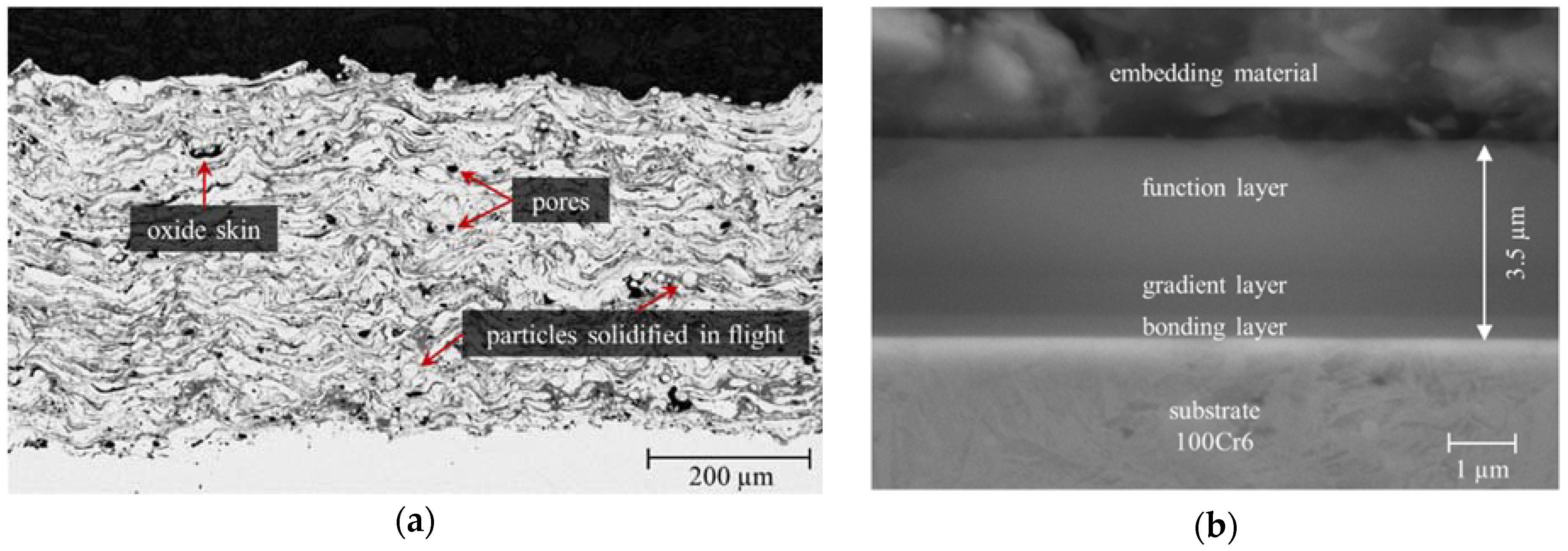
The pin material for tribological experiments was chosen to represent a DLC coated piston ring while the disk material has been selected to represent a modern cylinder liner surface of a combustion engine. The plasma thermal wire arc (PTWA) spray coating (Terolab Surface GmbH, Langenfeld, Germany) applied to grey cast iron (EN-GJL-250) was deposited from a low-carbon steel (EN 10016-2) and had a thickness of up to 500 μm after deposition. The coating showed typical microscopically large inhomogeneities, characterized by pores, oxides and particles that had already solidified in flight. Figure 1 shows a cross section of the coating and the DLC layer.
The average Vickers hardness of the sprayed layer is 400HV0.3 and due to the 3% to 5% porosity of the PTWA coating, the density is approx. 7.42 g/cm3 instead of the usual 7.86 g/cm3 of the solid material.
For finishing, the coated disks were conventionally ground flat on both sides by Kiffe Engineering GmbH, Villingen-Schwenningen, Germany (cBN as hard phase, honing oil as cooling lubricant), which should come close to the surface quality of the cylinder honing (Ra = 0.4 µm; Rz = 4.4 µm).
The DLC-coated pins were a hydrogen-containing amorphous carbon (a-C:H) with a hydrogen content of approx. 25% and a 25–30% sp2 and 45–50% sp3 hybridization, which was deposited at the Fraunhofer IWM with the help of plasma-assisted CVD. The layer (see Figure 1b) consists of a bonding layer (Si-containing DLC, starting material tetramethylsilane), a gradient layer (exchange of the starting materials tetramethylsilane for toluene) and a functional layer (made of toluene). The process gases were mixed with 50% argon at a process pressure of 1.4 Pa. The acceleration voltage of the plasma (bias voltage) was approx. 500 V. The layer thickness of the DLC coating is up to 3.5 μm with an E-modulus of 158 GPa and a hardness of 1800 HV 0.003.
2.2. Lubricant and OME
Fuchs TITAN GT1 LONGLIFE III 5W-30 at a constant temperature of 80 °C was used as engine oil for the tests. The chemical formula of OME is H3CO–(CH2–O)n–CH3 with the repeating functional group (CH2–O)n, called oxymethyl. The number n of oxymethyl units determines the molecular size and properties of the biofuel and is a mixture of 3 to 5 for the present study. The dynamic viscosity at 80 °C for OME is only 0.7 mPas compared to 15.4 mPas of the engine oil. The OME fuel for the experiments was provided by the Institute of Catalysis Research and Technology (IFKT) of the Karlsruhe Institute of Technology.
2.3. Tribometry
The friction experiments were carried out on a pin-on-disk tribometer (POD) SST from TETRA Gesellschaft für Sensorik, Robotik und Automation mbH. In order to avoid external temperature influences, the laboratory was air-conditioned and thus kept at a constant temperature. The temperature in the oil circuit was controlled by a circulation thermostat. Part of the circuit was also the RNT wear measuring system. The RNT system was operated using the so-called concentration method which measures the wear particle concentration in the lubricant [7]. In order to correct for the half-life an activated reference sample was continuously measured in a second gamma detector.
In order to analyze the frictional behavior over time and to make statements about a possible running-in, a continuous run of three days with a constant load of 150 N (75 MPa) was carried out.
2.4. Analytical Techniques
In this work a PHI VersaProbe II from Ulvac-PHI Inc. (Hagisono, Japan) was used for chemical surface analysis of the disks. According to the manufacturer, the resolution of the device is 0.1 eV with a measuring spot of 200 μm. The sputtering rate for generating depth profiles was 2.5 nm/min with argon as process gas (1 kV, 500 nA).
A confocal microscope from Sensofar Tech S.L. (Barcelona, Spain) called PLµ 2300 was used to examine the topography of the pin surface and the disks. Due to a special sensor head, images can also be taken by white light interferometry by switching the measuring device. The measurement data were interpreted using the SensoMap Standard 6.2 evaluation software (Barcelona, Spain).
3. Results and Discussion
3.1. Tribological Results
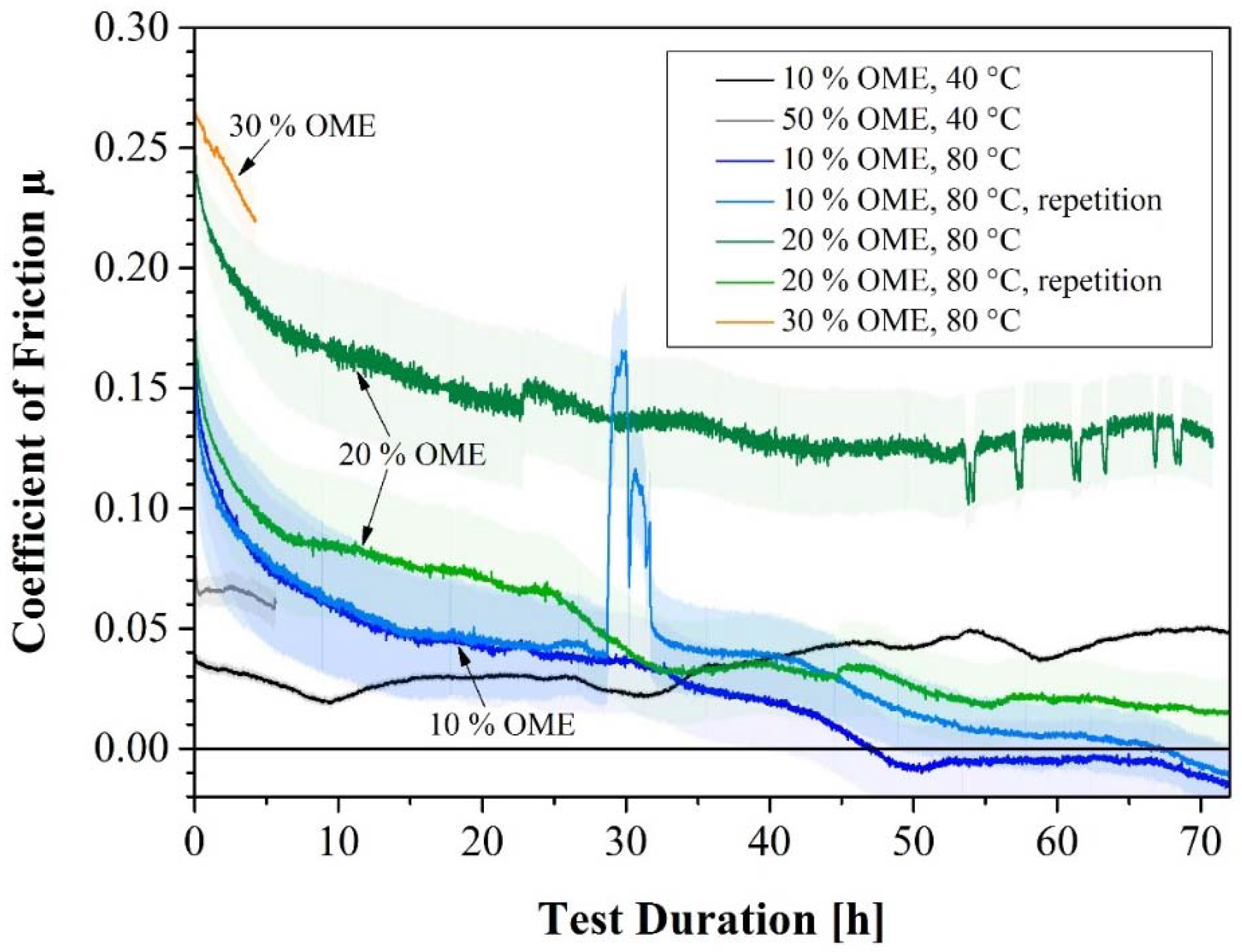
To study the influence of OME on friction, tribometer tests were carried out at different OME concentrations (Figure 2).
The friction coefficients that are plotted in Figure 2 as a function of the test duration correlate with the OME dilution at constant temperature. Friction increases with increasing OME concentration at the same temperature. In addition, a time dependence can be seen in a decrease of the coefficient of friction at high temperature and an increase at low temperature.
The continuous increase in the coefficient of friction of 10% OME at 40 °C can be explained by the evaporation of the biofuel. Due to the high viscosity of the lubricant mixture (29.2 mPas), the operating point at the beginning of the test is in the range of hydrodynamics. After evaporation of the OME, viscosity increases even further and approaches the value of pure engine oil at 40 °C (58.5 mPas).
With increasing OME concentration in the lubricating oil, the viscosity of the oil-OME mixture decreases further, so that the solid contact in the mixed friction regime continues to increase. Consequently, the coefficient of friction continues to increase.
Within the first 10 h of the OME tests at 80 °C, a rapid decrease in the coefficient of friction can be observed, which can also be explained by the evaporation of the OME and the higher load-bearing capacity of the lubricant. The friction coefficients in the negative are artifacts and were caused by zero point shifts of the force sensor. The absolute value of the shift is low but can affect the coefficient of friction in the hydrodynamic regime.
The described effect of viscosity reduction and the associated solid contact can also be determined on the surfaces of the DLC pins after tribological testing (Figure 3).
After the experiment, the DLC layers of the pins show wear marks on their surfaces. The amount of marks increases with increasing OME dilution. The pin with 30% OME in the lubricant even has a deep crater reaching down to the substrate. Although distinct groove structures are present on the pin surfaces, the underlying wear mechanism is most likely carbon diffusion, which is typically found in DLC friction contacts [8]. Abrasive wear is rather unusual with DLC systems [9]. Furthermore, it is noticeable that at 30% OME dilution the DLC layer is ablated down to the substrate. The sharp edges of the wear mark indicate delamination as another wear mechanism.
Figure 4 compares the friction coefficients of 10% OME at 40 and 80 °C with those of pure engine oil.
At 80 °C, the coefficient of friction is initially higher due to the reduced viscosity caused by the dilution with OME and the reduced viscosity of the base oil at that temperature. During the experiment the friction drops strongly, which we attribute to the evaporation of OME. Towards the end of the experiment the COF of undiluted and diluted oils are the same within the scatter of the data. For the diluted oil with 10% OME that is tested at 40 °C of the viscosity of the base oil is expected to be higher than at 80 °C, but due to the OME content, which does not evaporate, the friction is slightly higher than the pure base oil.
The addition of OME to the lubricating oil generally reduces viscosity. Friction partners can thus be separated less effectively from each other and the formation of a load-bearing lubricating film can be prevented. From a content of 30% OME (80 °C), no hydrodynamic conditions are achieved under the predefined test conditions. Operating points with very low coefficients of friction (e.g., at 2.5 m/s, 150 N) are already shifted at 10% OME into the mixed friction regime with a growing proportion of solid state friction. This trend is further intensified with increasing OME concentration, as can be seen in Figure 5, where all friction data is plotted over the Hersey-number H = ηv/p, where η denotes the viscosity, v is the entrainment speed, and p the normal load. The Hersey number is related the oil film thickness and indicates the lubrication regime.
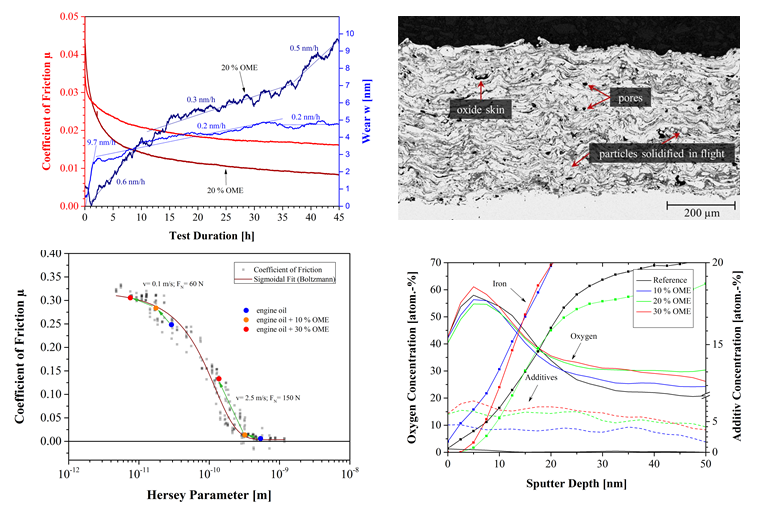
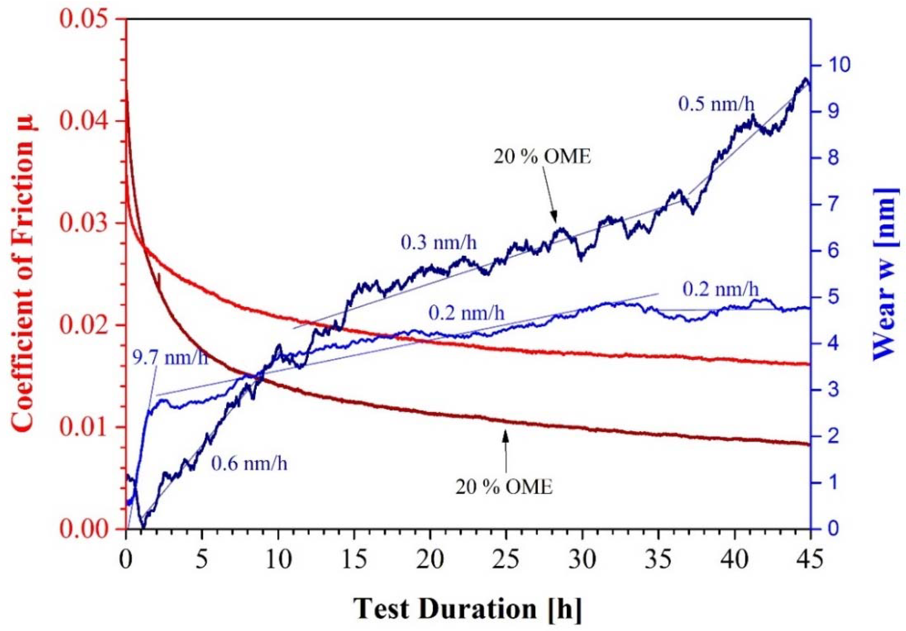
Figure 6 shows the RNT tests with the correlated friction curves.
The resolution limit of the radionuclide technique depends on the labelling and is approx. 0.1 μg/h (=0.05 nm/h for this sample).
In the tests with engine oil and engine oil plus 20% OME, the wear rates were below 1 nm/h. Due to the lower load-bearing capacity of the lubricating film of the oil thinned with 20% OME, higher contact pressures initially prevailed in the tribological system, which explain the higher beginning of the coefficient of friction.
3.2. Elemental Composition of the Worn Samples
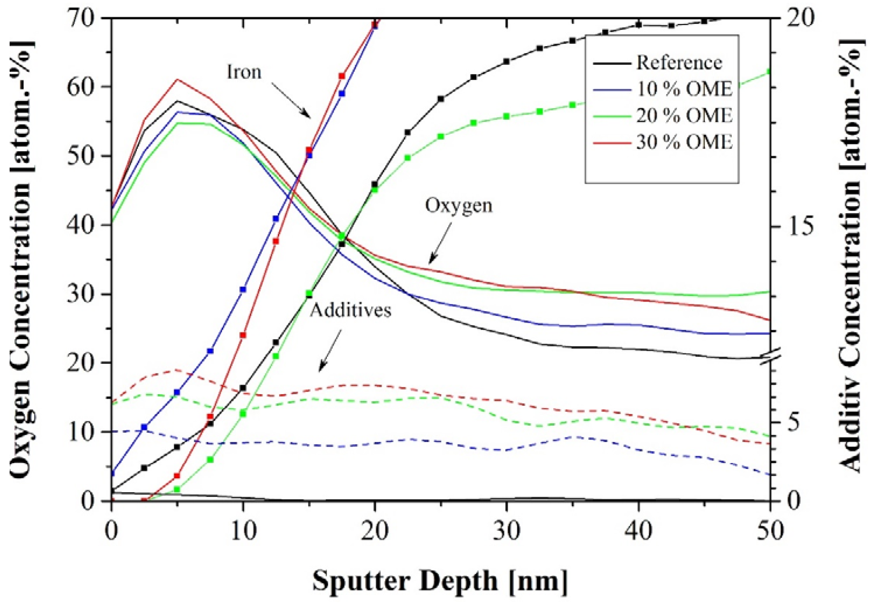
The admixture of the biofuel could also have favored the formation of ZnDTP (zinc-dialkyl-dithiophosphate) layers, as higher friction densities were converted with increasing OME concentration. In Ref. [10] it was found that an oil dilution with ethanol in the tribological system DLC-cast iron had positively influenced the layer formation of ZnDTP and thus a lower wear could be measured. Oxymethylene ether could have had a similar effect in this context, which could explain the lower wear rates within the first 5 h. The initially strong drop in the coefficient of friction at 20% OME can mainly be associated with the evaporation of the OME and the resulting increase in viscosity. The drop in the friction value below that of the test with pure engine oil could be due to the increased formation of a friction-reducing third body with the participation of ZnDTP. In order to clarify this situation, photoelectron spectroscopic measurements (XPS) was used to analyze the sliding tracks on the disks, which were tested with pure engine oil and with an OME content (Figure 7).
In all sliding tracks, a comparable depth profile (concentration and depth) of the oxygen concentration was detected independently of the OME content in the lubricant. Roughness on the length scale of the measurement area (several nm at 200 µm spot size) can in general influence the course of the depth signal but since all measured depth profiles show the same depth-concentration trend, does not affect the comparison of different OME concentrations. Therefore, a corrosive effect of oxymethylenether can be ruled out during the friction process. This is confirmed when the reference measurement (black) and the measurement at 30% OME (red) are compared in Figure 6. Moreover, with an oxidative effect of OME, the values of 10% and 20% OME within the first 15 nm sputter depth should not be below the reference measurement. The oxygen content, which does not disappear at a depth of 50 nm, must be caused by oxidation of the spray particles during thermal spraying.
Furthermore, a correlation between the oxygen concentration and the concentration of the additives at a depth of more than 30 nm is found. As the OME concentration increases, oxides of the additives, namely Ca, Zn and P, are increasingly detected, which also led to an increase in the oxygen concentration at greater sputter depths.
By adding OME to the lubricating oil, the viscosity decreases so that the friction power density in the tribological contact increases. The friction track could have been exposed to locally higher temperatures, which could have caused ZnDTP to adsorb to the steel surface. With increasing OME content, the frictional stress increases due to a higher solid content and the formation of tribological layers becomes more probable. This assumption was confirmed by the increase in additive oxides, which had to be measured as the biofuel content increased.
4. Summary and Conclusions
In order to further optimize the efficiency of today’s internal combustion engines, coatings were applied to the piston ring and cylinder liner to reduce internal engine friction and wear.
In tribological tests, oxymethylene ether was used as a fuel additive, which can also come into contact with engine oil in internal combustion engines by mixing. For this reason, the oxidative and corrosive influence of OME on friction and wear of the PTWA coating was investigated using the model system with radionuclide technology. With the help of XPS measurements, the steel spray coating was chemically analyzed after the friction tests and checked for corrosion. In addition, confocal microscope images were taken to assess the surface topographies.
The evaluation of the RNT investigations with and without OME showed comparable wear rates in the one- and two-digit nanometer per hour regime as required for modern combustion engines. However, the addition of OME reduces the viscosity of the oil so that the friction partners are more difficult to separate from each other, which led to an increase in the coefficient of friction. No corrosion of the sprayed steel layer could be detected by surface chemical analyses, so that the use of OME as fuel makes sense if oil-side measures for viscosity stabilization are taken. Thus, the pairing of a-C:H tested here in contact with an iron spray layer can be seen as a promising tribological system for engine operation with OME and should be examined more closely in engine tests.
Author Contributions
Conceptualization, M.D. and R.B.; Methodology, H.-J.W. and R.B.; Experimental and Analytics, H.-J.W. and R.B.; Writing-Original Draft Preparation, R.B. and M.S.; Supervision and Project Administration, M.D and R.B.; Funding Acquisition, Revision of the Manuscript, M.D.
Funding
The work presented here was carried out as part of an initialization project of the “Profilregion Mobilitätssysteme Karlsruhe”, which was funded in equal parts by the Fraunhofer-Gesellschaft and the State of Baden-Württemberg, the Ministry of Science, Research and the Arts and the Ministry of Economics, Labour and Housing.
Conflicts of Interest
The authors declare no conflict of interest.
References
- Wong, V.W.; Tung, S.C. Overview of automotive engine friction and reduction trends—Effects of surface, material, and lubricant-additive technologies. Friction 2016, 4, 1–28. [Google Scholar] [CrossRef]
- Graham, L.A.; Rideout, G.; Rosenblatt, D.; Hendren, J. Greenhouse gas emissions from heavy-duty vehicles. Atmos. Environ. 2008, 42, 4665–4681. [Google Scholar] [CrossRef]
- Nguyen, V.H.; Pham, P.X. Biodiesels: Oxidizing enhancers to improve CI engine performance and emission quality. Fuel 2015, 154, 293–300. [Google Scholar] [CrossRef]
- Ernst, P.; Barbezat, G. Thermal spray applications in powertrain contribute to the saving of energy and material resources. Surf. Coat. Technol. 2008, 202, 4428–4431. [Google Scholar] [CrossRef]
- Amin, S.; Panchal, H. A Review on Thermal Spray Coating Processes. Int. J. Curr. Trends Eng. Res. 2016, 2, 556–563. [Google Scholar]
- Hofmann, D.; Kunkel, S.; Bewilogua, K.; Wittorf, R. From DLC to Si-DLC based layer systems with optimized properties for tribological applications. Surf. Coat. Technol. 2013, 215, 357–363. [Google Scholar] [CrossRef]
- Scherge, M.; Pöhlmann, K.; Gervé, A. Wear measurement using radionuclide-technique (RNT). Wear 2003, 254, 801–817. [Google Scholar] [CrossRef]
- Aboua, K.A.M.; Umehara, N.; Kousaka, H.; Deng, X.; Tasdemir, H.A.; Mabuchi, Y.; Higuchi, T.; Kawaguchi, M. Effect of carbon diffusion on friction and wear properties of diamond-like carbon in boundary base oil lubrication. Tribol. Int. 2016, 113, 389–398. [Google Scholar] [CrossRef]
- Erdemir, A.; Donnet, C. Tribology of diamond-like carbon films: Recent progress and future prospects. J. Phys. D 2006, 39, 18. [Google Scholar] [CrossRef]
- Banerji, A.; Lukitsch, M.J.; Alpas, A.T. Friction reduction mechanisms in cast iron sliding against DLC: Effect of biofuel (E85) diluted engine oil. Wear 2016, 368–369, 196–209. [Google Scholar] [CrossRef]
Figure 1.
(a) Structure of the sprayed EN10016-2 steel layer; (b) Structure of the diamond-like carbon coating (DLC layer).
Figure 1.
(a) Structure of the sprayed EN10016-2 steel layer; (b) Structure of the diamond-like carbon coating (DLC layer).

Figure 2.
Coefficient of friction at different OME concentrations. The moving average value is displayed and the corresponding raw data is shown in the background in the same color.
Figure 2.
Coefficient of friction at different OME concentrations. The moving average value is displayed and the corresponding raw data is shown in the background in the same color.

Figure 3.
Confocal microscopy images of the worn DLC pins after the tribological testing.

Figure 4.
Coefficient of friction of engine oil tested at 80 °C (red solid line) and engine oil plus 10% OME at 40 °C (black solid line) and 80 °C (blue solid line). Raw data is shown in the background in the same color.
Figure 4.
Coefficient of friction of engine oil tested at 80 °C (red solid line) and engine oil plus 10% OME at 40 °C (black solid line) and 80 °C (blue solid line). Raw data is shown in the background in the same color.

Figure 5.
Stribeck curve of the lubricated system DLC-spray coating and with OME dilution. The coefficients of friction (COF) were determined by varying the speed between 0.1 and 2.5 m/s and the normal force in the range between 60 N and 240 N. The COF is plotted against the Hersey parameter ηv/p, where η is the viscosity of the blend, v the entrainment speed and p the normal load.

Figure 6.
Friction and wear of experiments with engine oil (light colors) and engine oil plus 20% OME (dark colors).
Figure 6.
Friction and wear of experiments with engine oil (light colors) and engine oil plus 20% OME (dark colors).

Figure 7.
Photoelectron spectroscopic measurements (XPS) measurements in the friction tracks. Oxygen depth profiles for different OME concentrations are plotted as solid lines. The summed-up signal of typical anti-wear additive elements (Ca, Zn and P) as dashed lines and the iron profile of the base materials as squares.

© 2018 by the authors. Licensee MDPI, Basel, Switzerland. This article is an open access article distributed under the terms and conditions of the Creative Commons Attribution (CC BY) license (http://creativecommons.org/licenses/by/4.0/).
Share and Cite
MDPI and ACS Style
Böttcher, R.; Winkler, H.-J.; Dienwiebel, M.; Scherge, M. Tribology of Wire Arc Spray Coatings under the Influence of Regenerative Fuels. Lubricants 2018, 6, 60. https://doi.org/10.3390/lubricants6030060
AMA Style
Böttcher R, Winkler H-J, Dienwiebel M, Scherge M. Tribology of Wire Arc Spray Coatings under the Influence of Regenerative Fuels. Lubricants. 2018; 6(3):60. https://doi.org/10.3390/lubricants6030060
Chicago/Turabian StyleBöttcher, Roman, Hans-Jörg Winkler, Martin Dienwiebel, and Matthias Scherge. 2018. "Tribology of Wire Arc Spray Coatings under the Influence of Regenerative Fuels" Lubricants 6, no. 3: 60. https://doi.org/10.3390/lubricants6030060
Note that from the first issue of 2016, this journal uses article numbers instead of page numbers. See further details here.