1. Introduction
Friction has a key role in several applications in our daily lives. In some applications, high friction is desirable, as in tires, brakes, clutches, and frictional power transmission systems. In other applications the friction is required to be minimized, in order to improve energy efficiency, component durability, and overall system reliability. For example, the energy loss due to friction in automobiles is estimated to be approximately 40% of the total energy generated by the internal combustion engine [
1]. In all the above-mentioned cases, understanding the complex mechanisms involved in friction, and the means to control/regulate it, is necessary. Various approaches have been classically employed in order to control friction, some of which are the adoption of a lubrication technique, or the surface functionalization (e.g., through coating) of the tribo-pair.
Among all the available techniques for surface functionalization, about three decades ago attention was drawn to surface patterning, named also surface texturing, as an effective means to improve the tribological performance in terms of reducing the wear, friction [
2,
3], and lubrication consumption (sometimes delivered in conjunction with ex-situ coatings, such as DLCs [
4], or in-situ coatings such as titanium oxides [
5]). Such surface structural modification (here, the term
structural only refers to the
geometrical modifications micro-fabricated on the surface since no qualitative variation of the metallurgic properties is usually delivered on the surface confinement during femtosecond laser ablation), usually corresponding to the creation of an array of microscale surface simple geometrical defects (such as holes or grooves), has been independently achieved through the application of different techniques, including vibro-rolling [
6], reactive ion etching [
7], and laser surface texturing (LST) [
8]. However, the latter technique seems to offer the most promising concept [
9], due to its high flexibility, as well as to its structural features such as shape, size, density, and depth, which can be varied relatively easily. In particular, LST provides an excellent control of the micro-structures by simply controlling the laser parameters, together with the short processing times due to the availability of the extremely fast laser and laser mechatronic machining setup. In addition, recent progress in femtosecond laser surface texturing may further reduce collateral damage such as debris and recast layers by reduction of pulse duration [
10].
An effective surface texturing must be fabricated with a proper optimization of the geometrical parameters based upon the application in hand. The optimization of the parameters includes the aspect ratio of the dimples, their shape [
11,
12,
13], their area density [
14], and, in cases of the partial surface texturing, the textured portion [
15]. In both conditions, either the fully textured or partially textured surface, the research interest has been mainly concentrated on a regular array of surface micro-cavities, which is the easiest choice both on the theoretical as well as on the micro-machining side. As an example, in the case of lubricated conformal sliding contacts, it has been shown that regular and uniform patterns of hemispheric micro-cavities lead to a reduction in the friction coefficient [
2,
3,
16,
17,
18] with respect to the untextured pair. Interestingly, the friction reduction mechanisms, induced by these micro-holes, are different depending on the lubrication regime under investigation [
19].
In the boundary and mixed lubricated regimes (for relatively low values of the product of viscosity and sliding speed), the micro-dimpled texture acts as an oil reservoir for trapping wear debris [
9] which, therefore, do not participate to the frictional and wear interfacial processes. In the hydrodynamic lubrication regime, instead, depending on the macroscopic geometric properties of the contact, as well as on the extension of the micro-textured area to a fraction (known as partial surface texturing) or to the whole contact domain (known as total surface texturing), a number of competing local effects can occur. Those are the reduction of the shear stress on the dimples location, cavitation, or the formation of eddy-like flows at the bottom of the cavities. They are causing the friction reduction or, rather, increase, depending on the geometry of the dimples and their area coverage, as well as on their networking on the surface [
20,
21,
22].
Recently, it has been theoretically demonstrated [
21,
22] that a regular array of surface micro-cavities is not able to provide the topmost tribological performance (e.g., smallest friction), which is, however, theoretically available for the given macro-contact geometry when adopting inhomogeneous micro-structural properties. Indeed, the adoption of an optimized non-homogeneous array of surface defects can provide superior friction and load support performances, suggesting the existence of
super bearings configurations [
22]. In particular, the adoption of a non-homogeneous distribution of defects with a local misalignment with respect to the sliding direction allows for the setting of the local micro-fluid dynamics in an extremely controllable fashion because of the configurable local effective anisotropy of the interface flow conductance [
22].
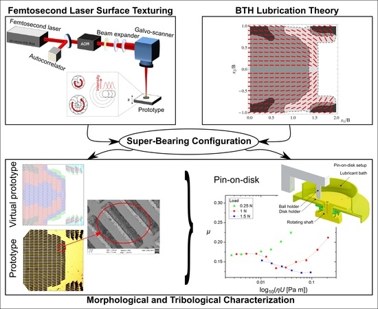
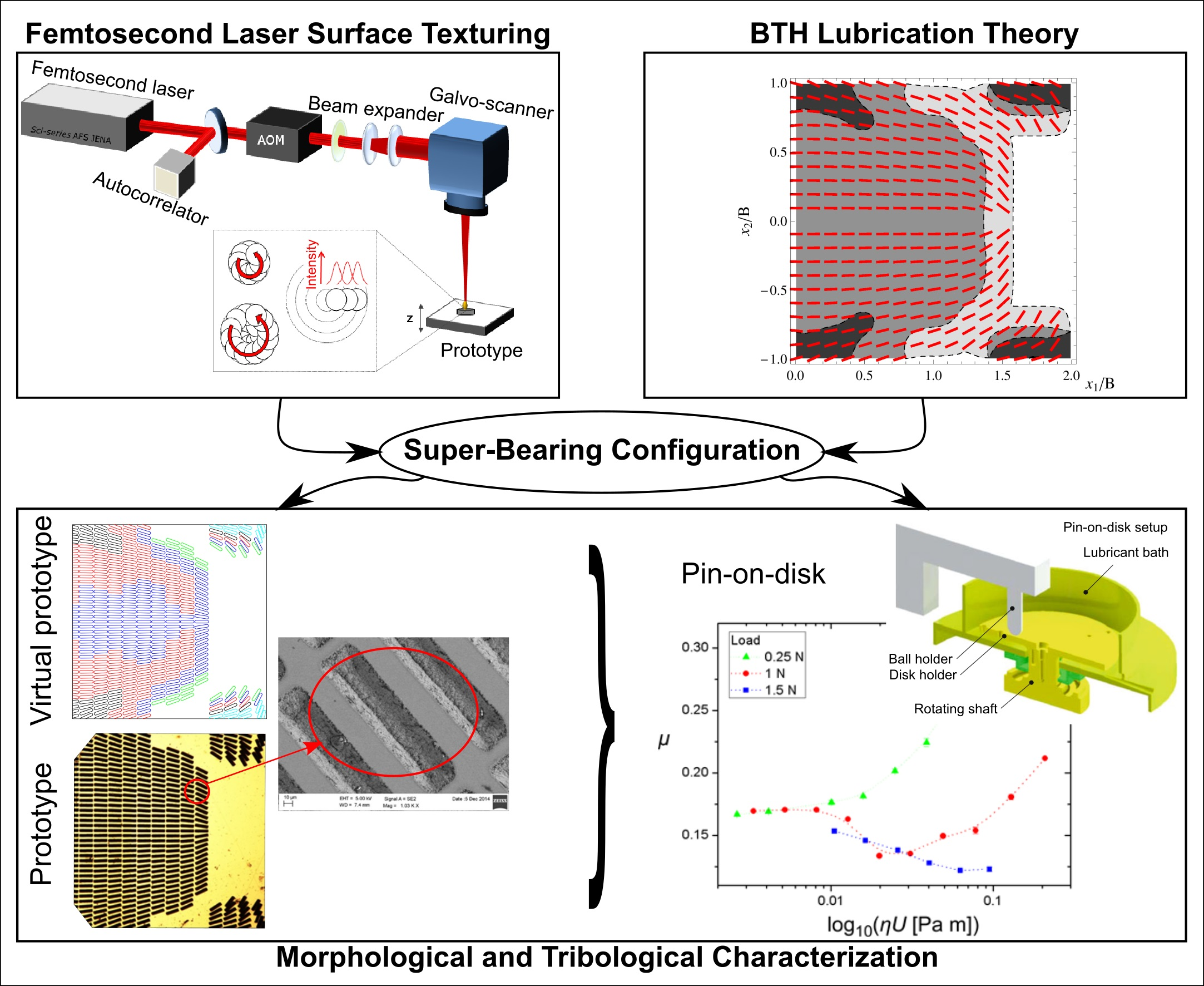
Inspired by such theoretical achievements, in this paper we exploit the flexibility of laser surface texturing in order to fabricate the optimal non-homogeneous micro-texture predicted by the Bruggeman Texture Hydrodynamics theory [
21] for a square un-tapered bearing pad geometry. The resulting micro-structured surfaces are then preliminary tribologically tested in fully-flooded lubricated conditions in order to verify the existence of a macro-hydrodynamic friction regime induced by the collective flow actions of the micro-structural defects. The latter, interestingly, would otherwise not be possible for the initial untextured surface (untapered geometry).
The manuscript is outlined as follows. In
Section 2 the overall design and functionality of the partially textured pad is illustrated.
Section 3 describes the procedures to fabricate and characterize the samples. In
Section 4, the tribological performances of the laser textured pad prototypes are presented and discussed. Finally, the conclusion follows.
2. Super-Bearings with Enhanced Load Support and Low-Friction
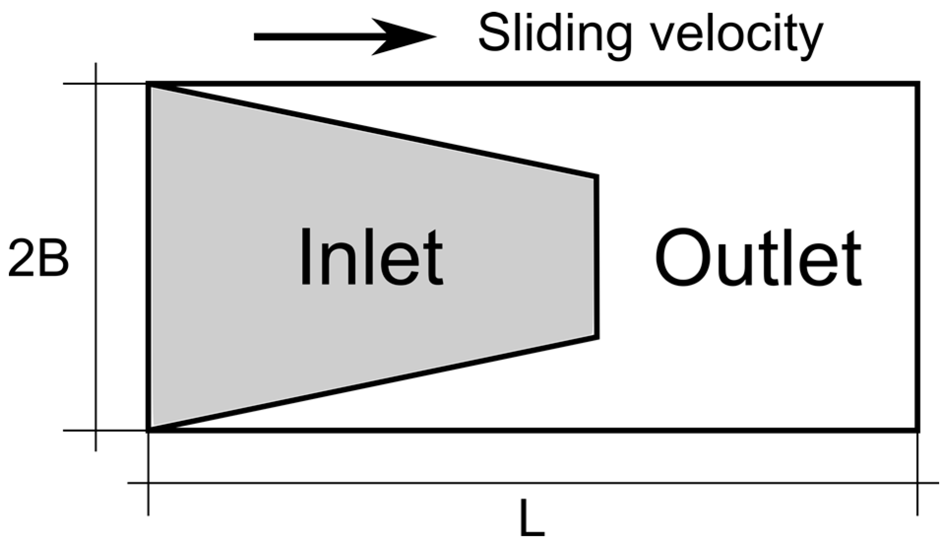
In a recent paper by one of us, it has been theoretically postulated that the existence of particularly effective texture geometries, which maximize the load supported by a single thrust bearing pad of finite width 2B and length L (schematic representation shown in
Figure 1), are subjected to a partial surface texturing [
22]. The textured surface consists of an array of small-scale defects, which include different textured geometries like circular, elliptical dimples, and/or micro-grooves. We assume that the sliding contact takes place between the partially textured and plain parallel surfaces, under the iso-viscous rigid lubrication regime and isothermal conditions. An analytical model has been developed under these conditions, which accurately describes the texture hydrodynamics [
20]. The theoretical model allows for the calculation of the average flow dynamics at the contact interface, in terms of the flow and the shear stress tensorial factors, provided that cavitation is absent or it has a negligible effect (as is usually the case of partial surface textures).
The hydrodynamic problem can be solved for different texture geometries with variable area density, lattice constants (describing the array size and configuration), dimple depths, shape, and orientation. It has been found that an efficient way to reduce friction and increase the load support in the bearing is to design a special texture, which retains the lubricant flow under the sliding interface, in particular by minimizing the side leakage. Although being beneficial to friction reduction, it is shown that an isotropic lattice of circular dimples fails to redirect the lubricant flow because it provides isotropic conductivities [
22]. On the other hand, striped superficial defects are well known to produce anisotropic flow redistribution [
20,
22]. In the case of texturing with micro-grooves extending all over the contact surface (total texturing), a friction increase has been experimentally reported. However, this effect has been ascribed to the escape of the lubricant out of the contact area due to the major flow conductivities along the parallel micro-ducts, associated with the transversal grooved texture [
2]. Therefore, in order to maximize the flow retaining effect, both the local micro-scaled geometry of the texture features and their mutual interaction at the macro-scale have to be optimized. The theoretical model predicts that the best solution consists of a partial texture characterized by a lattice of finite-sized grooves having a certain local angular misalignment with respect to the sliding direction. The distribution of the striped dimples depends on the pad aspect ratio.
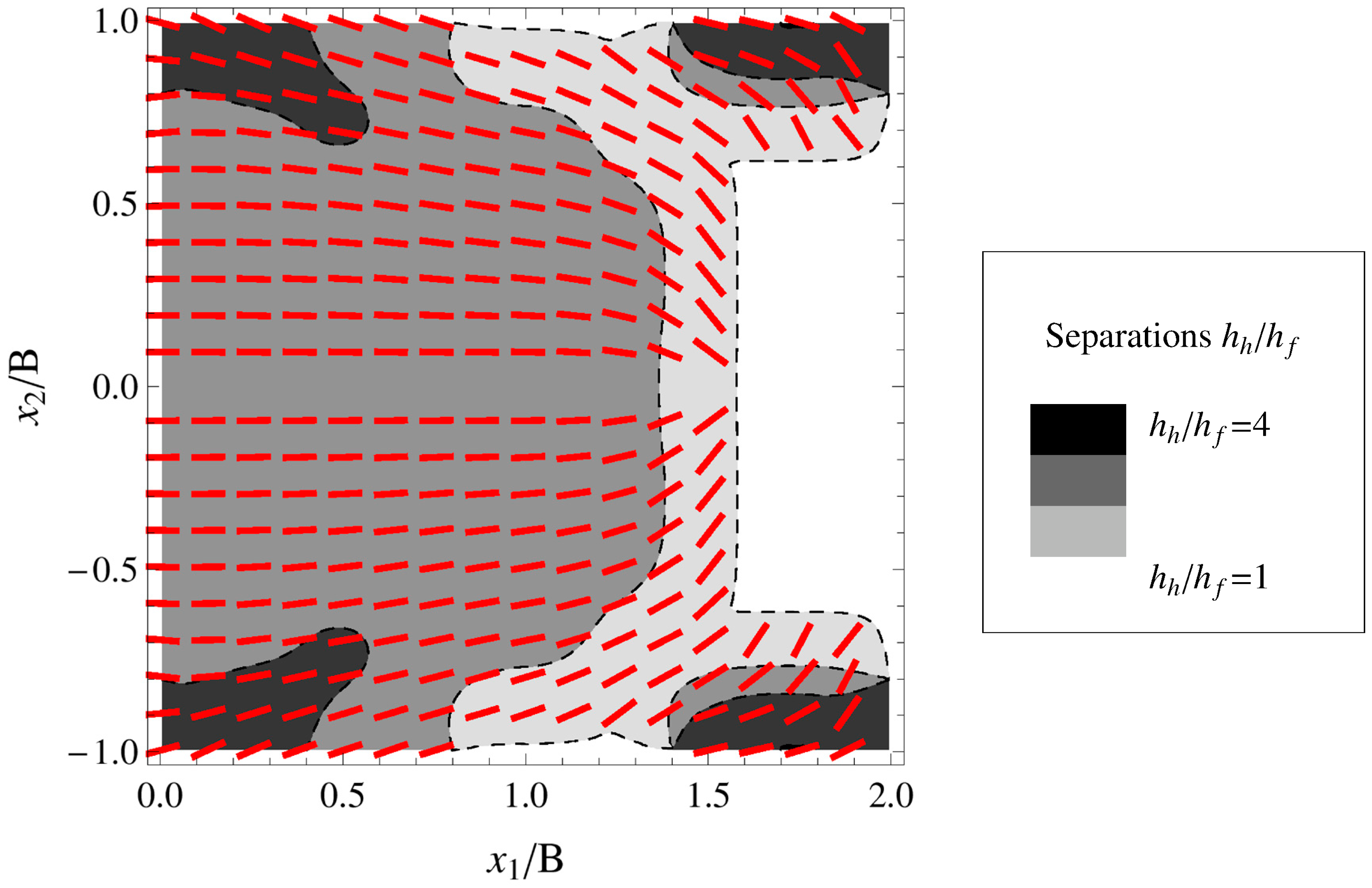
One of the proposed optimal texture geometries, calculated by adopting a multigrid optimization procedure based on a genetic algorithm, is depicted in
Figure 2 for the square pad geometry. In the figure, the red stripes show the local angular alignment of the grooves. The number of the stripes, which have been drawn in the
Figure 2, have only a qualitative purpose, i.e., they do not represent the lattice spacing and the dimensions of the defects, nor have they been somehow scaled. They only represent the areas where the dimples are located over the squared pad, as well as their orientation. We observe that the microgrooves have been aligned in such a way to hinder the flow of the lubricant towards the lateral direction, thus preventing any immediate leakage and, hence, friction increase. Furthermore, the stripes inclination close to the lateral boundaries enables the redirecting of the fluid, at a scale larger than the scale of the grooves, towards the internal portion of the domain, through a micro-herringbone construction. This determines a large number of fluid particles sheared at the contact interface and, consequently, an increase in the bearing pressure.
In addition, expulsion fingers have been created on the outlet corners of the pad with the aim of lengthening the fluid path under the pad domain. Indeed, the expulsion fingers redirect part of the flow, which normally would exit from the middle part of the rear side, toward the rear part of the pad. In this way, each fluid particle exerts a prolonged shearing action. Such a combination of expulsion fingers and micro-herringbone geometry significantly increases the load support capabilities to the extremely lengthened particle route under the contact. This finally positively affects friction, which is consequently reduced due to an increased mean interfacial separation.
3. Experimental Procedure
3.1. Sample Preparation
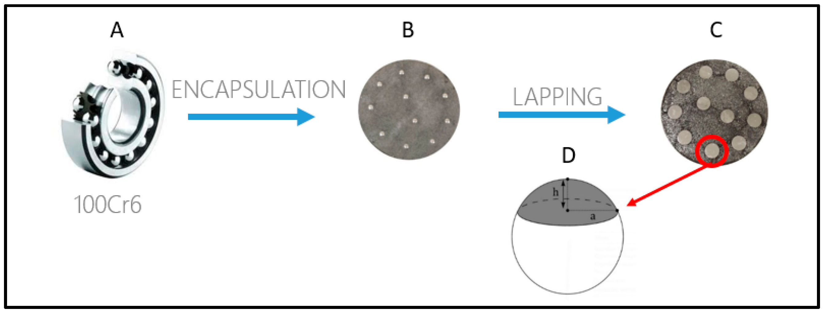
The experiments were performed with the adoption of 100Cr6 steel spheres from commercial bearings (
Figure 3A). The spherical caps were firstly encapsulated in a resin cylinder (
Figure 3B) and then truncated by lapping (
Figure 3C) in order to obtain a flat circular surface with a diameter 2
a of about 4 mm (
Figure 3D). Such flat surfaces correspond to our laboratory prototypes of bearing pads. Before being subjected to the laser surface texturing process, the samples were polished at a root-mean-square surface roughness of about 20 nm, as verified by atomic force microscopy.
3.2. Surface Texturing by Femtosecond Laser Ablation
The fabrication of the surfaces on the truncated spherical caps was performed by using an ultrafast fiber CPA laser system (mod. Sci-series from Active Fiber Systems GmbH, Jena, Germany) delivering 650 fs pulses with a maximum laser power of 50 W, a wavelength of 1030 nm, a pulse energy up to 100 μJ, and a repetition rate ranging from 50 kHz to 10 MHz. In particular, the LST surfaces presented in this research work were produced by operating at the lowest achievable repetition rate of 50 kHz and an average power of 50 mW. The high level of accuracy and reproducibility of the ablated micro-features is, indeed, only achieved by working near threshold laser fluence.
The linearly polarized beam coming from the laser source was firstly converted into circularly polarized light through a quarter-wave plate to prevent anisotropic absorption on the ablating surface and, after passing through a suitable beam expander, directed towards a 14-mm aperture galvo-scan head (mod. HurryScan from ScanLab GmbH, Puchheim, Germany) equipped with a 100-mm focal length F-Theta lens. The focused spot size on the sample surface was about 15 μm.
Three of the circular truncated surfaces, obtained with the procedure described in
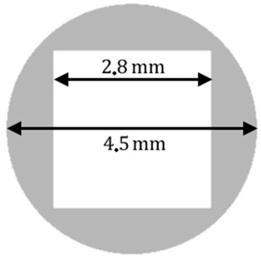
Section 3.1, were laser-machined as follows. The grey area in
Figure 4 of the circular sample outside an about 2.8-mm-side square was removed by femtosecond laser milling reaching a depth of more than 100 μm, which is an order of magnitude higher than the expected average fluid thickness under the bearing. We have used one of the milled samples as a flat control squared pad. The other two samples were further laser machined.
As according to the theoretical design, which is described in
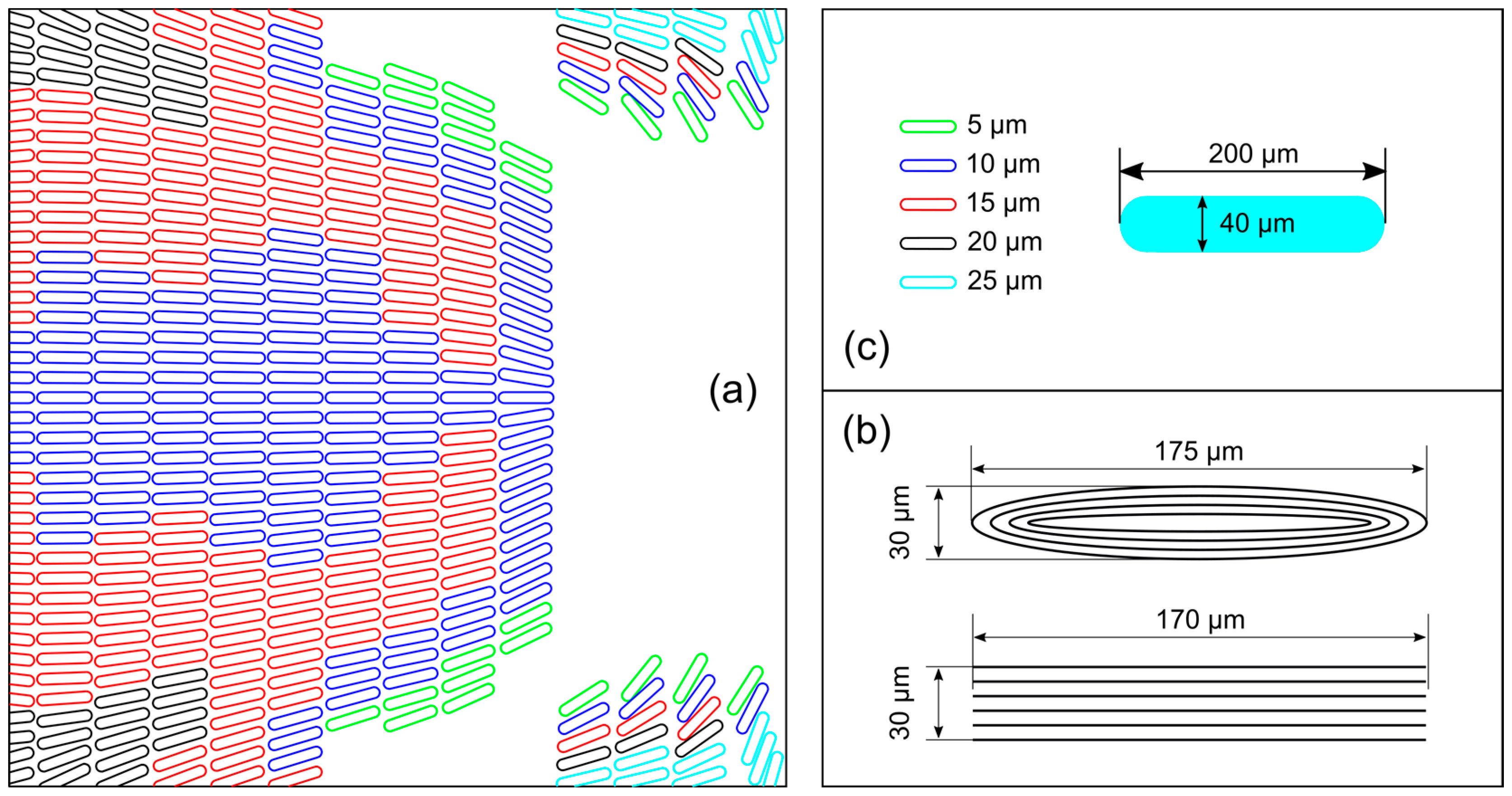
Figure 2, a texture pattern composed of five groups of micro-grooved dimples at different depths, ranging from 5 to 25 μm (
Figure 5a), was machined inside the squared section. Each dimple is contained within an imaginary square cell of length 200 μm length and width 40 μm, as represented in
Figure 5b. The area ratio of the texture is about 50%. The deeper dimples have been positioned in the suction and expulsion fingers located at the corners of the textured area. The variable inclination of the dimples with respect to the sliding direction follows the red stripes, as shown in
Figure 2, which aim to guide the fluid towards the internal part of the pad.
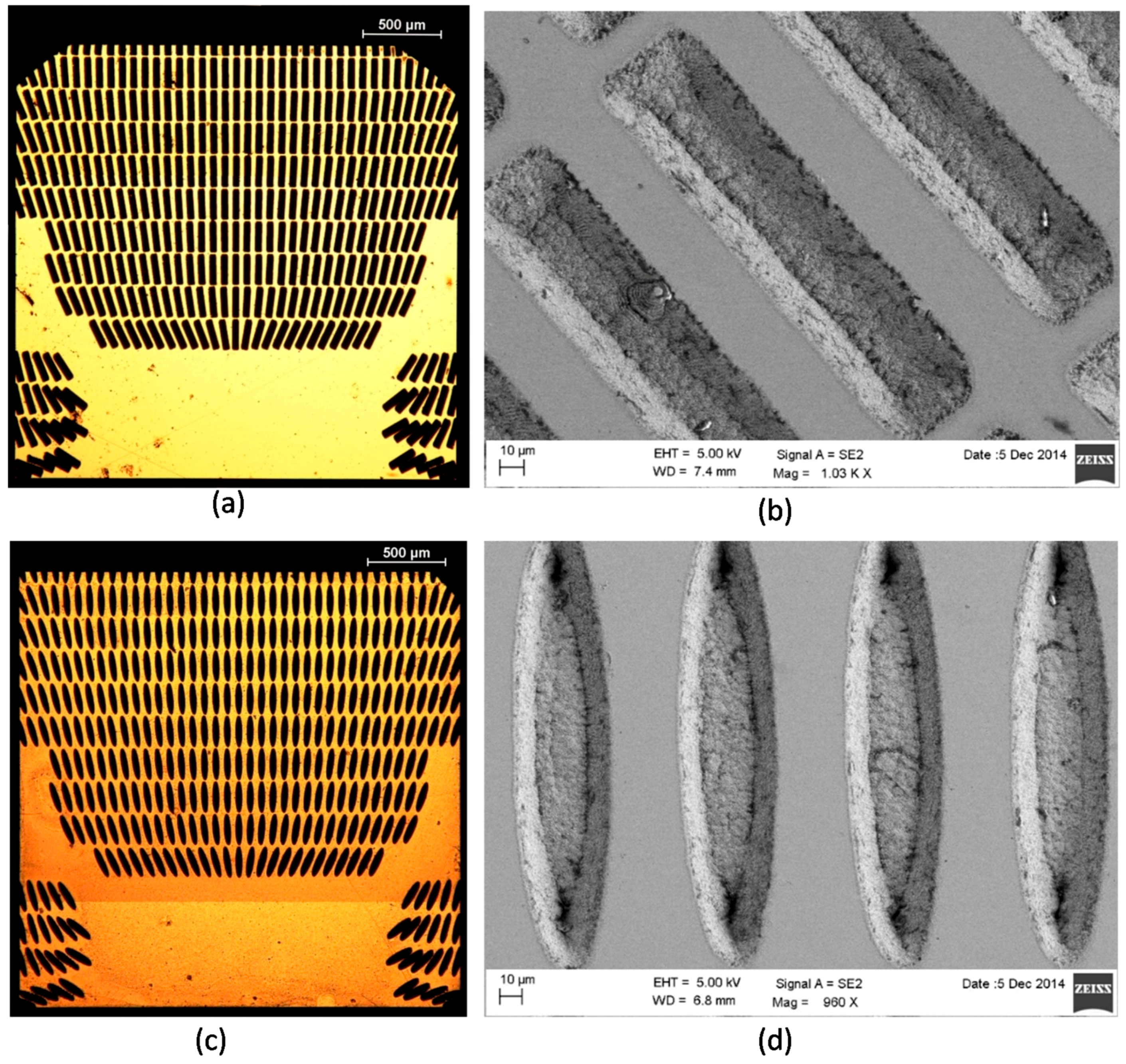
The two laser textured samples differ in the way the dimples were realized. In one sample, dimples of elliptical shape were fabricated by moving the laser beam along a path of four concentric ellipses with a hatch distance of 3 μm. In the other sample, each dimple was micro-machined by drawing an array of equidistant parallel ablation traces with a lateral displacement of 3 μm one from each other, resulting in a micro-groove of almost rectangular shape (see
Figure 5c).
Following the scheme of
Figure 5a, the ablation depth of each dimple was accurately controlled by adjusting the number of overlapped loops. In
Table 1, the number of loops executed to target each dimple depth is reported according to the dimple geometry. The translation speed of the focused laser beam on the sample surface was held constant at 20 mm/s. After the femtosecond laser surface micro-texturing, the samples were cleaned in an ultrasonic bath to remove the loosely attached ablation debris.
3.3. Morphological Characterization
The morphology of the fabricated micro-features was characterized by optical and scanning electron microscopy (Field Emission SEM mod. SIGMA from Zeiss, Oberkochen, Germany), as well as by using a white light confocal microscope by CSM-Instruments with lateral and vertical resolutions of, respectively, 1.1 μm and 0.005 μm.
Figure 6 shows an overall view acquired with an optical microscope of the worked area of the two samples with rectangular and elliptical dimples, respectively, together with high magnification SEM images of some micro-grooved dimples. The machined part is completely free from melting and burrs, due to the high level of accuracy provided by the ultrashort pulse duration ablation regime, together with the near threshold laser fluence selected for the LST process.
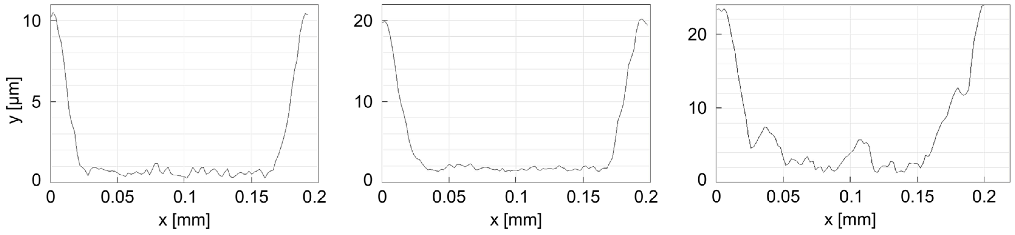
The confocal microscope analysis confirmed that the depth of the dimples met the required specifics with micrometer precision, as, for example, reported in
Figure 7 in case of rectangular dimple with three different depths of 10 μm, 15 μm, and 20 μm, corresponding to 9, 14, and 19 laser scanning loops, respectively. However, as it can be already noticed in
Figure 7c, with the increase of the number of loops and the dimple depth, some morphological defects start to appear. In particular, the bottom of the dimples is more irregular and the vertical walls are more tapered. This effect can be ascribed to the attenuation of the laser fluence hitting the bottom of the dimples as far as the depth increases. Working already at a near threshold ablation fluence, the material removal mechanism becomes less efficient, causing metal particles re-deposition inside the dimples. It has been observed that such an effect is even more pronounced in case of elliptical dimples.
3.4. Tribological Characterization
The tribological characterization of the LST samples was carried out on a CSM High Temperature pin-on-disk Tribometer (HTT). The contact pair is represented by a rotating sample-disk (Aluminum Alloy 6061 sheet with a measured root-mean-square surface roughness of Ra = 0.08 μm) in contact with the laser-textured truncated spheres, where disk and pin-end were immersed in a lubricant bath of a pure mineral oil (Oroil Therm 7 from Orlandi Lubrificanti S.r.l., Argenta, Italy). Lubricant temperature was constantly monitored during the tests. A normal load was applied to the sphere holder by means of a calibrated weight.
The following tribology experiments were conducted on the samples. Firstly, the Stribeck curves of the two (elliptical and rectangular dimple patterns) laser textured pads, applying a load of 1 N, were measured and compared, aiming to find out which of the two dimple geometries yielded the best tribological performance. Each measurement consisted of several steps. During each step, the disc was rotated at a constant speed while the tangential displacement value of the elastic supporting arm of the ball holder was detected by a Linear Variable Displacement Transducer (LVDT). The displacement sensor signal was converted via software into a tangential force value T through a suitable calibration curve. Being known the normal load
N, the total friction coefficient
was calculated by (the ratio of the tangential force
T with the normal force):
The friction coefficient μ between the two surfaces was obtained from:
where
is the friction coefficient between the ball holder and the lubricant oil, which was experimentally estimated by raising the arm and separating thus the two surfaces. Following this procedure, the friction coefficients of the two laser-textured pads at different sliding velocity
U of the disk ranging from 324 mm/s to 15.0 mm/s were determined and plotted. We started with the fastest speed, where the lubrication regime was always of the hydrodynamic type, and changed it towards slower values in each step. This practice was adopted to strongly minimize any possible undetectable surface wear. Each measurement was repeated 5 times in order to have a mean value of
with its related error, along with constant monitoring of the oil temperature. Before testing on another sample or at another condition, all components of the tribometer that came into contact with the lubricating oil were carefully cleaned and the aluminum base was polished.
The laser textured pad exhibiting the best tribological performance was further investigated by measuring the Stribeck curves in case of three different loads of 0.25 N, 1.0 N, and 1.5 N, respectively.
Finally, in order to evaluate the hydrodynamic contribution of the anisotropic texture pattern, the tribological behaviors of the texturized sample and the control untextured one were compared by operating the tribometer in reciprocating mode. In this mode the rotation speed is periodically inverted with a frequency that can be set by software. The LVDT sensor still estimates the tangential force value (T) which is, in this case, alternatively positive and negative. Alternately reversing the sliding contact direction with respect to the texture distribution allows for better highlighting of the anisotropic behavior of the texture pattern. These last measurements were conducted at a constant temperature of 24 ± 2 °C, a rotating speed of 0.136 m/s, a normal load of 0.25 N, and a reversing frequency of 1 Hz.
4. Results and Discussion
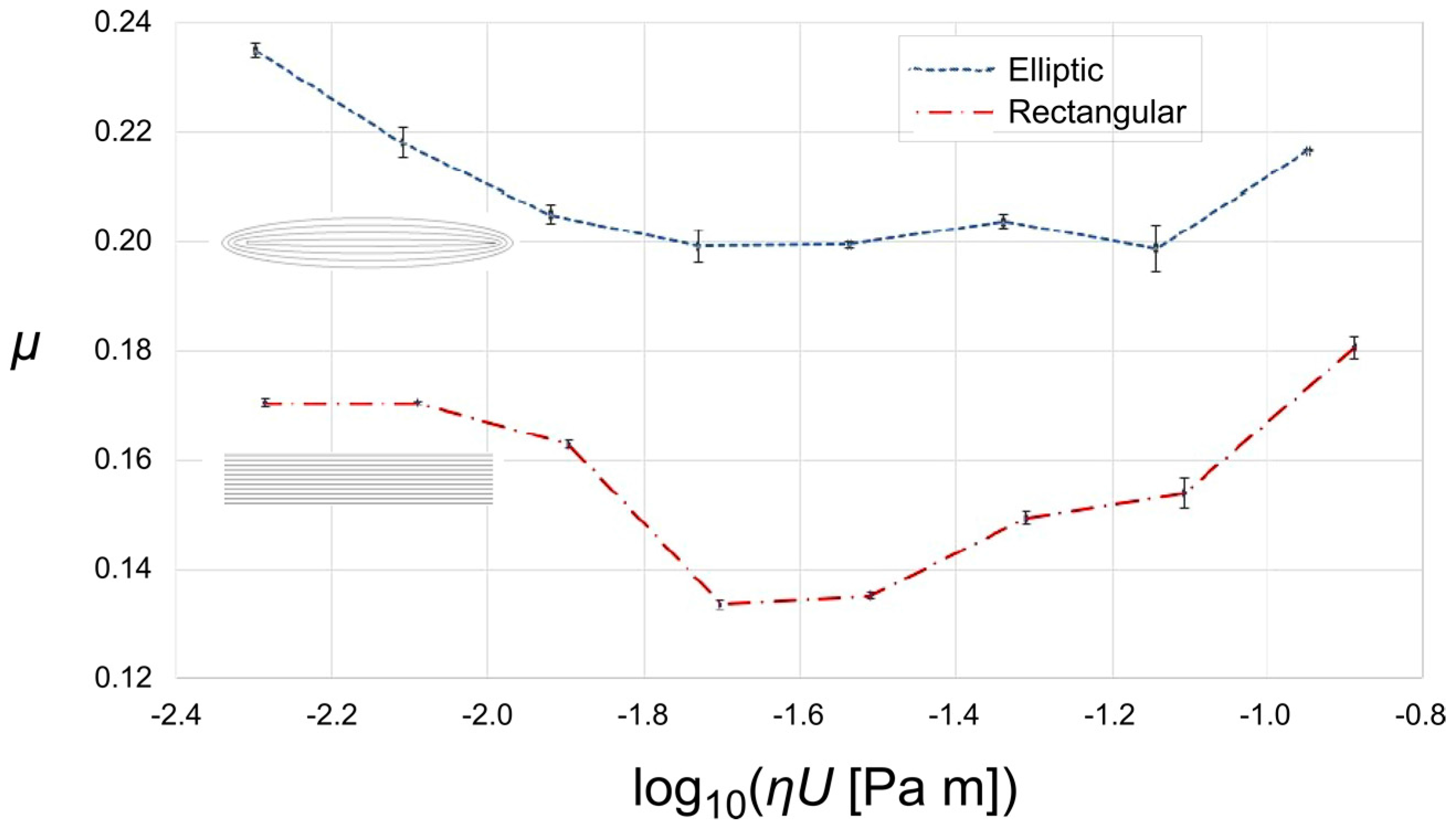
The comparison of the tribological behavior of the textured pads with elliptical and rectangular dimples at different sliding speeds is represented in
Figure 8. From the Stribeck curves, both obtained by maintaining a constant temperature of 20 °C and applying a load of 1 N, the three lubrication regimes can be easily recognized. At sliding speeds slower than 0.03 m/s, the measured friction coefficient is relatively high, typical of the boundary lubrication.
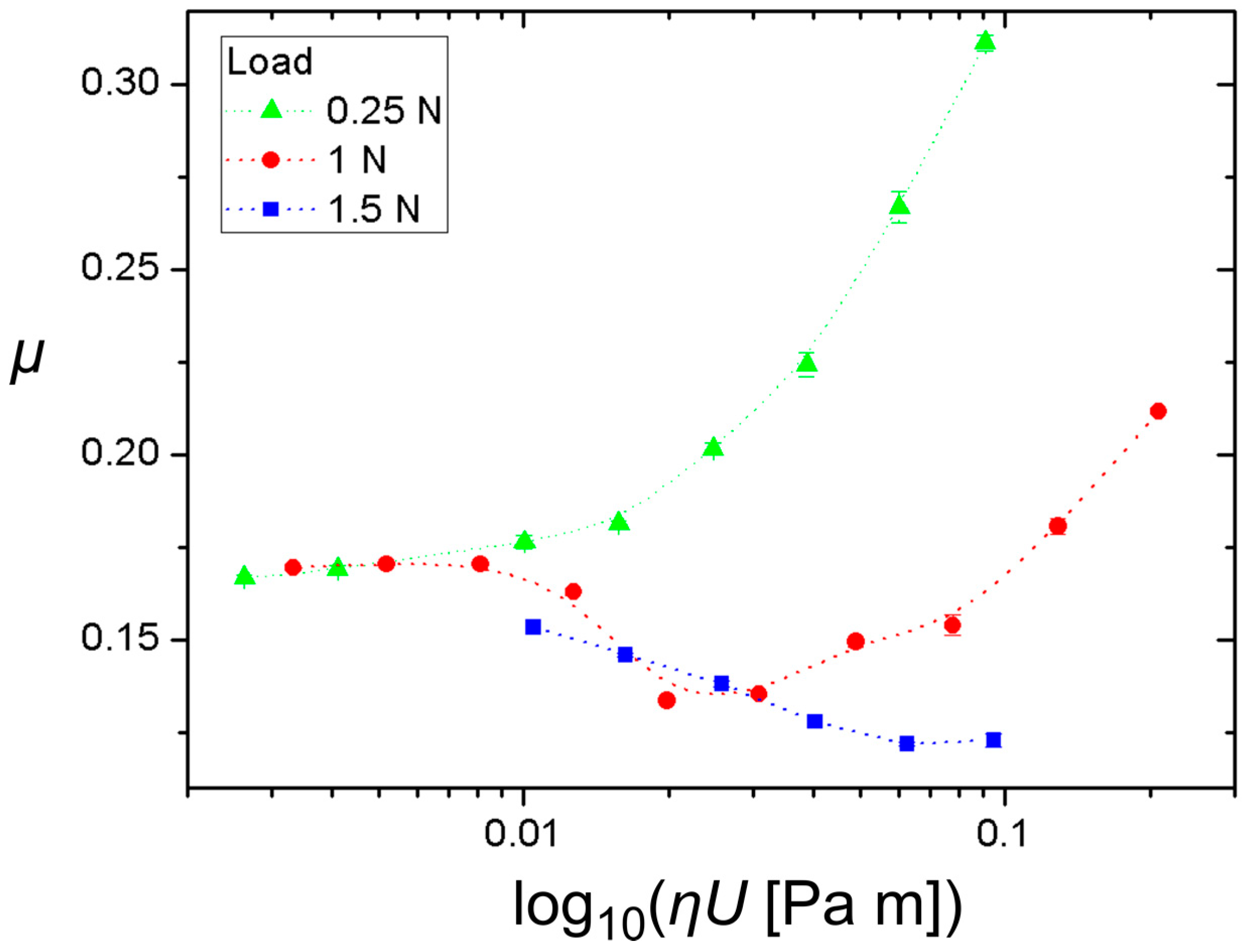
For speeds in the range between 0.04 and 0.1 m/s, a mixed lubrication regime is established and the friction coefficient decreases until, by further increasing the speed above 0.2 m/s, it starts growing again because of the fluid hydrodynamic resistance. Although the trend of the two Stribeck curves is similar, it can be noticed that the friction coefficient measured for the pad with elliptical dimple texturing (sample E) is always approximately 20% higher compared to the rectangular geometry (sample L). This is explained by the greater number of morphological defects noticed at the bottom of the deepest elliptical dimples. The more the texture geometry differs from the theoretical design, the less effective is the collective contribution of the dimple pattern to reduce friction. This consideration also applies to the smaller area coverage of the elliptical texture with respect to the rectangular texture. Indeed, in this study the obtained different texture area density is the consequence of keeping an equal lattice spacing between the two textures (in order to reduce the experimental parameters). Unfortunately, this leads to a larger boundary contact area in the boundary regime and to a lower average interfacial separation (in the inlet zone) in the hydrodynamic regime for the elliptical texture, with a consequent friction increase. Since it showed better tribological performances, the pad with the rectangular dimple pattern was further investigated by measuring the Stribeck curves at three different loads, i.e., 0.25 N, 1 N, and 1.5 N, with linear sliding speeds ranging from 324 mm/s to 15.0 mm/s. The results are illustrated in
Figure 9, where it is clearly noticeable that, especially for the load below 1 N, the designed anisotropic texture pattern generates a hydrodynamic lubrication regime in a wide range of sliding speeds. We stress that such hydrodynamic regime is the fingerprint of the anisotropic texture, given that it would not be produced through the wet sliding contact of the untextured surface. In addition, it is worth noticing that for the highest load of 1.5 N, the friction coefficient significantly reduces at values below 0.13 for sliding speed faster than 0.1 m/s, as related to the occurrence of the friction minimum in the mixed lubrication regime.
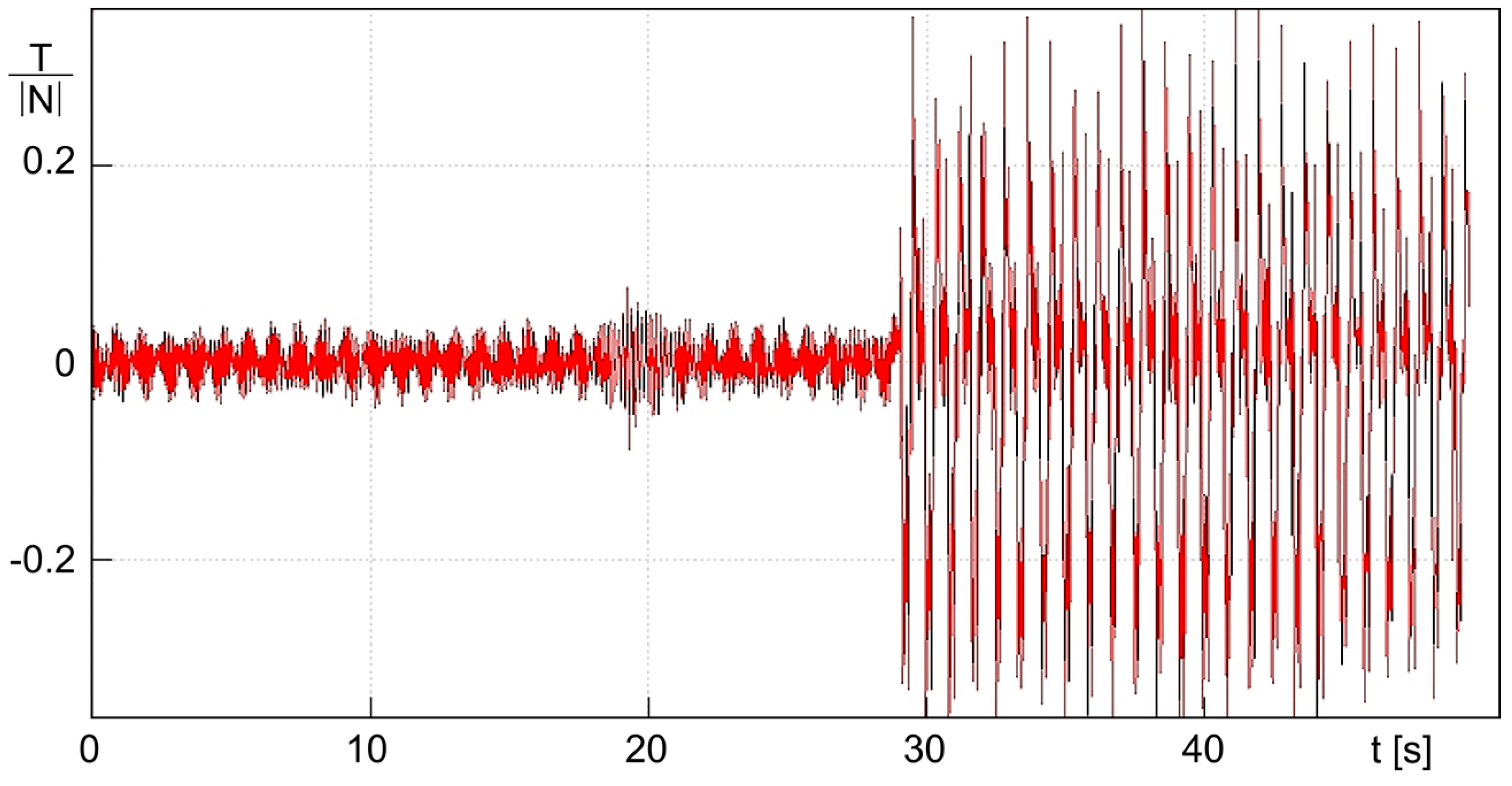
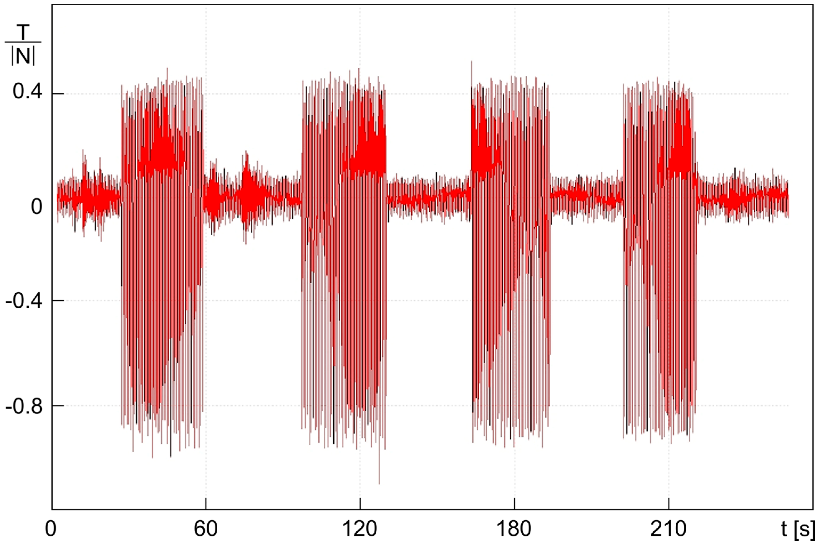
Finally, we have tested our textured samples under reciprocating sliding contact, in order to highlight the effect of sliding speed direction and texture anisotropy on the friction. In particular, we have measured the friction force on the flat control surface and on the textured sample “L” as a function of the reciprocating motion time in
Figure 10 and
Figure 11, respectively. The measurements have been performed keeping the oil bath temperature at a constant value of 24 ± 2 °C, the average sliding speed at 136 mm/s, and applying a normal load of 0.25 N. The sliding speed was periodically reversed with a frequency of 1 Hz. In both graphs, the ratio between the measured (apparent) tangential force and the normal load is reported as a function of contact time. In the first approximately 30 s of the measurements, the arm of the tribometer was raised and the tangential force is relatively low oscillating with positive/negative small values around the zero, according to the rotation direction of the disc. When the arm was lowered, the tangential force absolute value is much higher exhibiting the same oscillation behavior.
However, in the case of the untextured control sample (
Figure 10), the oscillations are symmetric with respect to the zero, as must be expected.
The textured sample results shown in
Figure 11 reveal, instead, a substantial asymmetry of the oscillation amplitudes. Here, the tangential force is twice as intense when the direction of rotation is opposite to that for which the texture pattern has been designed. The same measurement was repeated for four different time intervals, obtaining similar behaviors and thus proving confidence in the results and supporting the existence of the micro-hydrodynamic collective contribution originated by the anisotropic surface microstructures.
5. Conclusions
Exploiting the high level of precision and flexibility achievable through femtosecond laser ablation, square un-tapered bearing pads with non-uniform surface micro-texturing have been fabricated starting from flattened steel spheres. Specifically, an innovative texture pattern design was implemented consisting of a non-homogeneous array of surface micro-grooved dimples of different depths, inclinations and distribution. Such a geometry was inspired by previous studies that, based on the BTH theory, aimed to develop and optimize a surface micro-pattern enabling a macro-hydrodynamic friction regime during lubricated sliding contact. According to the theoretical predictions, this regime is entirely due to the collective flow action of the micro-structural defects, and it could not be established in the case of a flat untextured surface. The specific micro-grooved dimples depth, orientation and spatial distribution enable, indeed, better retaining the lubricant under the pad and/or redirecting part of it towards the internal pad portion through appositively developed suction fingers. This collective micro-fluid-dynamic action of the dimples was expected to increase significantly the pad load support capabilities.
Following the theoretical non-uniform surface texture design, two different pads were fabricated which differed in the shape of the micro-dimples and the ablation strategy implemented to produce each dimple. In one sample, dimples of elliptical shape were fabricated with concentric laser beam elliptical paths, while in the second sample rectangular dimples were produced with a hatch of parallel ablation lines. The ablation depth of each dimple was finely controlled by adjusting the number of loops. However, the confocal microscope morphological characterization revealed an increase of the walls taper with the depth, as well as the appearance of some asperities at the bottom, especially in case of elliptical dimples.
The tribological behavior of each textured pad was investigated using a pin-on-disk tribometer. The rectangular dimple textured pad exhibited an overall lubricated friction coefficient which was approximately 20% lower than the elliptical dimple counterpart. The improved tribological performance was ascribed to the better morphology of the rectangular dimples.
A further tribological investigation of this last sample at varying loads revealed that, especially for loads below 1 N, the designed anisotropic texture pattern generates a hydrodynamic lubrication regime that is not expected for the conformal contact of two flat surfaces in the investigated range of sliding speeds. This is also confirmed by the absence of any wear sign on the pad surface after the tribological characterization. Finally, it was found that the friction coefficient of the textured pad was almost doubled when reversing the rotating direction of the tribometer disk in reciprocating mode. This results strengthens the hypothesis that the hydrodynamic regime is established only when the sliding direction the one for which the non-uniform texture pattern has been designed in order to produce a collective micro-fluid-dynamic action. On the contrary, the untextured control pad showed equivalent friction coefficient values irrespective of the sliding direction in reciprocating mode.
The experimental results presented in this work are very promising and demonstrates that non-uniform surface texturing allows developing a new generation of so-called “super-bearings”, with unique and enhanced tribological performances that, in addition, can be tailored according to the sliding direction. Further experimental studies will be provided in the future on these aspects.

 ,
, 


